EP3627826A1 - Control apparatus, image capturing apparatus, control method, program, and storage medium - Google Patents
Control apparatus, image capturing apparatus, control method, program, and storage medium Download PDFInfo
- Publication number
- EP3627826A1 EP3627826A1 EP19197799.0A EP19197799A EP3627826A1 EP 3627826 A1 EP3627826 A1 EP 3627826A1 EP 19197799 A EP19197799 A EP 19197799A EP 3627826 A1 EP3627826 A1 EP 3627826A1
- Authority
- EP
- European Patent Office
- Prior art keywords
- areas
- focusing
- evaluation value
- focus
- control apparatus
- Prior art date
- Legal status (The legal status is an assumption and is not a legal conclusion. Google has not performed a legal analysis and makes no representation as to the accuracy of the status listed.)
- Withdrawn
Links
- 238000000034 method Methods 0.000 title claims description 39
- 238000011156 evaluation Methods 0.000 claims abstract description 185
- 230000008859 change Effects 0.000 claims description 9
- 230000003287 optical effect Effects 0.000 claims description 6
- 230000008569 process Effects 0.000 description 29
- 238000010586 diagram Methods 0.000 description 12
- 238000012545 processing Methods 0.000 description 10
- 230000010365 information processing Effects 0.000 description 8
- 238000012937 correction Methods 0.000 description 6
- 230000006870 function Effects 0.000 description 5
- 238000004590 computer program Methods 0.000 description 3
- 230000003247 decreasing effect Effects 0.000 description 3
- 238000011161 development Methods 0.000 description 3
- 238000006243 chemical reaction Methods 0.000 description 2
- 230000000694 effects Effects 0.000 description 2
- 238000013459 approach Methods 0.000 description 1
- 230000007423 decrease Effects 0.000 description 1
- 238000012986 modification Methods 0.000 description 1
- 230000004048 modification Effects 0.000 description 1
- 230000004044 response Effects 0.000 description 1
Images






Classifications
-
- G—PHYSICS
- G02—OPTICS
- G02B—OPTICAL ELEMENTS, SYSTEMS OR APPARATUS
- G02B7/00—Mountings, adjusting means, or light-tight connections, for optical elements
- G02B7/28—Systems for automatic generation of focusing signals
-
- H—ELECTRICITY
- H04—ELECTRIC COMMUNICATION TECHNIQUE
- H04N—PICTORIAL COMMUNICATION, e.g. TELEVISION
- H04N23/00—Cameras or camera modules comprising electronic image sensors; Control thereof
- H04N23/60—Control of cameras or camera modules
- H04N23/67—Focus control based on electronic image sensor signals
-
- G—PHYSICS
- G02—OPTICS
- G02B—OPTICAL ELEMENTS, SYSTEMS OR APPARATUS
- G02B7/00—Mountings, adjusting means, or light-tight connections, for optical elements
- G02B7/28—Systems for automatic generation of focusing signals
- G02B7/36—Systems for automatic generation of focusing signals using image sharpness techniques, e.g. image processing techniques for generating autofocus signals
-
- G—PHYSICS
- G03—PHOTOGRAPHY; CINEMATOGRAPHY; ANALOGOUS TECHNIQUES USING WAVES OTHER THAN OPTICAL WAVES; ELECTROGRAPHY; HOLOGRAPHY
- G03B—APPARATUS OR ARRANGEMENTS FOR TAKING PHOTOGRAPHS OR FOR PROJECTING OR VIEWING THEM; APPARATUS OR ARRANGEMENTS EMPLOYING ANALOGOUS TECHNIQUES USING WAVES OTHER THAN OPTICAL WAVES; ACCESSORIES THEREFOR
- G03B13/00—Viewfinders; Focusing aids for cameras; Means for focusing for cameras; Autofocus systems for cameras
- G03B13/32—Means for focusing
- G03B13/34—Power focusing
- G03B13/36—Autofocus systems
-
- H—ELECTRICITY
- H04—ELECTRIC COMMUNICATION TECHNIQUE
- H04N—PICTORIAL COMMUNICATION, e.g. TELEVISION
- H04N23/00—Cameras or camera modules comprising electronic image sensors; Control thereof
- H04N23/60—Control of cameras or camera modules
- H04N23/67—Focus control based on electronic image sensor signals
- H04N23/675—Focus control based on electronic image sensor signals comprising setting of focusing regions
Definitions
- the present invention relates to an image capturing apparatus, and more particularly to an image capturing apparatus that captures an image while fixing a focus position with manual focusing (MF).
- MF manual focusing
- image capturing may be performed while fixing a focus position by manual focus (MF).
- MF manual focus
- the focus position changes depending on a change in environment (image capturing state) such as temperature and humidity. For this reason, when the environment changes, there is a possibility that the image capturing cannot be performed while focusing on an intended object.
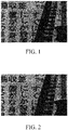
- FIG. 1 is an image focused on a metronome in front. If focusing is performed by AF when the focus is shifted due to the change in the environment from the state of the image illustrated in FIG. 1 , there is a possibility that a back chart will be in focus as illustrated in FIG. 2 .
- Japanese Patent Laid-Open No. 2009-103912 discloses an image capturing apparatus that performs determination by dividing an image into a plurality of areas.
- an area determined to be in focus first is selected to focus. For this reason, when the image capturing state changes, such as when a temporary object enters an area or when a peak position is lost due to noise or the like, focusing may be performed on an object different from the intended object.
- the present invention provides a control apparatus, an image capturing apparatus, a control method, a program, and a storage medium which are capable of acquiring an image in which an intended object is in focus even when an image capturing state is changed.
- the present invention in its first aspect provides a control apparatus as specified in claims 1 to 13.
- the present invention in its second aspect provides an image capturing apparatus as specified in claim 14.
- the present invention in its third aspect provides a control method as specified in claim 15.
- the present invention in its fourth aspect provides a program as specified in claim 16.
- the present invention in its fifth aspect provides a storage medium as specified in claim 17.
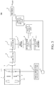
- FIG. 3 is a block diagram of an image capturing apparatus 100 in this embodiment.
- a lens unit (image capturing optical system) 1 is used to adjust a focal length or a focus position.
- the lens unit 1 includes an objective lens 1-1, an aperture stop 2, and a focus lens 1-2 that are arranged in a direction along an optical axis OA.
- An image sensor 3 receives light transmitted through the lens unit 1 to output an image signal. That is, the image sensor 3 performs photoelectric conversion on an optical image (object image) formed via the lens unit 1 to output the image signal.
- An AD converter 4 performs AD conversion on the image signal (analog signal) output from the image sensor 3 to be converted into a digital signal. The digital signal output from the AD converter 4 is input to an image processor 5.
- the image processor 5 performs image processing such as demosaicing, development processing, gamma processing, and sharpness processing on the digital signal to output image data.
- An encoder 6 compresses the image data output from the image processor 5 into JPEG or H.264 to be output to an external apparatus.
- An area setter (divider) 7 divides a captured image (image signal output from the image processor 5) into a plurality of areas.
- the image signal for area division may be either RGB before development or YCrCb after development.
- An evaluation value generator (calculator) 8 generates (calculates) an evaluation value (focus evaluation value, or AF evaluation value) for each of the areas divided by the area setter 7.
- the focus evaluation value is a contrast of the image signal in each area, and a peak position of the contrast corresponds to an in-focus position.
- An evaluation value memory (memory) 9 stores a plurality of areas with high focus evaluation values among the focus evaluation values output from the evaluation value generator 8.
- the area in which the focus evaluation value is to be stored is an area in which a plurality of objects exist and areas having high focus evaluation values can be selected by the predetermined number from the higher one.
- one or a plurality of focus evaluation values that are not less than a predetermined threshold value may be stored instead of being determined by the number.
- a focus search unit (focus adjuster) 10 uses a current focus evaluation value for each area generated by the evaluation value generator 8 and the focus evaluation value stored in the evaluation value memory 9 to perform focusing (focus adjustment).
- the focus search unit 10 calculates a local peak position based on the magnitude relationship between the focus evaluation values of the plurality of areas stored in the evaluation value memory 9 and the focus evaluation values of the plurality of areas generated by the evaluation value generator 8 to perform the focusing.
- the focus search unit 10 may perform control such that a ratio of the focus evaluation values of the plurality of areas generated by the evaluation value generator 8 approaches a ratio of the plurality of focus evaluation values stored in the evaluation value memory 9 (that is, such that the ratio of the focus evaluation values of the plurality of areas generated by the evaluation value generator 8 is within a predetermined range, or preferably coincident with the ratio of the plurality of focus evaluation values stored in the evaluation value memory 9).
- a temperature sensor (detector) 11 detects the temperature of the outside air or the internal temperature of the image capturing apparatus 100.
- a focus search restart unit 12 instructs the focus search unit 10 to perform focusing in accordance with changes in the temperature sensor 11, brightness Y obtained from the image processor 5, a humidity sensor (not illustrated), or the like.
- a focus operation instruction unit 13 instructs the focus lens 1-2 to perform focusing or manual focus operation according to a user's instruction or the like to drive the focus lens 1-2.
- the focus operation instruction unit 13 is a focus position fixing unit that fixes the focus position.
- the evaluation value memory 9 stores a focus evaluation value in the focus operation.
- FIG. 4 is a flowchart of the focusing process, and it illustrates a method of focusing in a range in which the magnitude relationship of the focus evaluation values stored in the evaluation value memory 9 is maintained.
- Each step in FIG. 4 is mainly performed by the evaluation value generator 8, the evaluation value memory 9, or the focus search unit 10.
- step S401 the evaluation value generator 8 calculates (generates) a focus evaluation value for each area (area of the captured image) in a screen (captured image, or display image) set by the area setter 7.
- step S402 the evaluation value memory 9 selects and stores a plurality (predetermined number) of areas having high focus evaluation values among the focus evaluation values generated by the evaluation value generator 8.
- step S403 the focus search unit 10 performs a focus search within a range in which the magnitude relationship between the plurality of focus evaluation values stored in the evaluation value memory 9 is maintained. That is, the focus search unit 10 performs focusing while maintaining the magnitude relationship between the focus evaluation value selected from the evaluation value memory 9 and the current focus evaluation value, and calculates a local peak position.
- step S404 the focus search unit 10 determines whether the magnitude relationship between the focus evaluation values of the plurality of areas stored in the evaluation value memory 9 is maintained after focusing. That is, the focus search unit 10 determines whether the magnitude relationship of the focus evaluation values of the plurality of areas after focusing is the same as the magnitude relationship of the focus evaluation values of the plurality of areas stored in the evaluation value memory 9.
- this flow focus search operation
- the process returns to step S403 and the focus search unit 10 performs focusing again.
- the focus search unit 10 determines that focusing cannot be performed, and the process may return to S401 or step S402.
- FIG. 5 is a flowchart of the focusing process, and it illustrates a method of performing focusing while maintaining a ratio of the focus evaluation values stored in the evaluation value memory 9.
- Each step in FIG. 5 is mainly performed by the evaluation value generator 8, the evaluation value memory 9, or the focus search unit 10.
- step S501 the evaluation value generator 8 calculates (generates) a focus evaluation value for each area (area of the captured image) in a screen (captured image, or display image) set by the area setter 7.
- step S502 the evaluation value memory 9 selects and stores a plurality (predetermined number) of areas having high focus evaluation values among the focus evaluation values generated by the evaluation value generator 8.
- step S503 the focus search unit 10 calculates the ratio of the focus evaluation values of the plurality of areas selected from the evaluation value memory 9.
- step S504 the focus search unit 10 performs focusing so that the focus evaluation value becomes the ratio of the focus evaluation values calculated in step S503. That is, the focus search unit 10 performs focusing so that the ratio of the focus evaluation values after focusing and the ratio of the focus evaluation values calculated in step S503 fall within a predetermined range (preferably, so that they coincide with each other).
- the focus search unit 10 may determine that an object has changed, such as movement of a vehicle. In this case, the focus search unit 10 updates the value stored in the evaluation value memory 9.
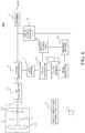
- FIG. 6 is a block diagram of an image capturing apparatus 100a in this embodiment.
- the evaluation value memory 9 acquires and stores the focus evaluation value of the area divided by the area setter 7 from the evaluation value generator 8. Unlike the first embodiment, the evaluation value memory 9 stores the focus evaluation value and the focus position acquired from the focus search unit 10 or the focus operation instruction unit 13 in association with each other.
- a peak detector 14 detects a peak position of the focus evaluation value stored in the evaluation value memory 9 and evaluates whether focusing is possible.
- a priority setter 15 calculates a distance between the peak position detected by the peak detector 14 and the current focus position, and sets the priority (order of priority) used for focusing on each area.
- FIG. 7 is a flowchart illustrating the priority setting process of the AF evaluation areas. Each step in FIG. 7 is mainly performed by the evaluation value memory 9, the peak detector 14, or the priority setter 15.
- FIG. 8 is an explanatory diagram of the AF evaluation areas.
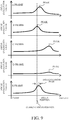
- FIG. 9 is an explanatory diagram of focus evaluation values.
- FIGs. 10A to 10C are setting examples of the AF evaluation areas. The flow of FIG. 7 is started by an MF operation or an AF operation by the user. In FIG. 7 , in order to simplify descriptions, five areas (A frame to E frame) in the evaluation areas illustrated in FIG. 8 will be described.
- the evaluation value memory 9 acquires the focus position and the focus evaluation value of each area from the focus operation instruction unit 13 and the evaluation value generator 8, respectively, and stores the correspondence relationship.
- FIG. 9 is an example of the correspondence relationship between the focus evaluation value and the focus position in the five areas (A frame to E frame) illustrated in FIG. 8 .
- the horizontal axis represents the focus position
- the vertical axis represents the focus evaluation value.
- step S702 the peak detector 14 determines whether the drive (focus drive) of the focus lens 1-2 is completed.
- the process returns to step S701.
- the focus drive is completed, the process proceeds to step S703.
- the determination process of step S702 may be performed based on whether the AF operation is completed.
- the peak detector 14 can determine whether a predetermined time has elapsed since the last operation.
- the peak detector 14 may be provided with a button that notifies the completion of the MF operation on the screen to perform the determination in response to the press of the button by the user.
- the peak detector 14 may acquire information on whether the drive motor is operating from the lens unit 1 to perform the determination.
- the peak detector 14 acquires the focus evaluation value of each area (evaluation area) from the evaluation value memory 9, and detects the peak position.
- the peak position can be detected by using known techniques. For example, the position of the maximum value of the focus evaluation value can be simply used as the peak position. Alternatively, the position of the maximum value among the focus evaluation values exceeding a predetermined threshold value may be used as the peak position.
- step S704 the priority setter 15 calculates the distance between the focus position last set by the user and the peak position of each area detected in step S703. This distance is used to set the priority in the subsequent step S705.
- step S705 the priority setter 15 sets priorities (orders of priorities) for the respective areas in order from the closest distance calculated in step S704. That is, the priority setter 15 sets the priority for the area to be higher as the area is closer to the in-focus state.
- the priority (order of priority) is in order of the B frame, the E frame, the A frame, the C frame, and the D frame.
- step S705 of FIG. 7 it is not necessary to set priorities in all the areas.
- the priorities may be set only for the area where the distance calculated in step S704 is not greater than a predetermined threshold value. This makes it possible to suppress the focus shift to an object at a distance.
- an area having a high focus evaluation value As a high priority or to set an area having a sharp peak in the focus evaluation value as a high priority.
- the same priority may be set to areas, and an area used for focusing may be appropriately selected according to the distance to the peak position or the like in the focusing process described below.
- the plurality of evaluation areas can be set so as to divide the area on the screen as illustrated in FIG. 10A .
- the plurality of evaluation areas may be discretely set to an arbitrary position on the screen as illustrated in FIG. 10B , or they may be set to have overlapping areas as illustrated in FIG. 10C .
- FIG. 11 is a flowchart of the focusing process. Each step in FIG. 11 is mainly performed by the evaluation value generator 8, the evaluation value memory 9, or the focus search unit 10 at fixed time intervals or every time the temperature changes by a fixed amount.
- the focus search unit 10 performs a focus search of a predetermined width (predetermined focus search width).
- the predetermined width is determined, for example, such that the amount of focus movement at the time of a temperature change measured in advance is contained.
- the evaluation value memory 9 stores the correspondence relationship between the focus position and the focus evaluation value of each area.
- FIG. 12A is an example of the correspondence relationship between the focus evaluation value and the focus position in the five areas illustrated in FIG. 8 (A frame to E frame). In FIG 12A , the horizontal axis represents the focus position, and the vertical axis represents the focus evaluation value.
- step S1102 of FIG. 11 the focus search unit 10 acquires, from the priority setter 15, the priority (order of priority) set to each area. Subsequently, in step S1103, the peak detector 14 selects an area (focus evaluation area) to be used in the evaluation as to whether focusing is possible in the subsequent step S1104 based on the priority acquired in step S1101.
- step S1104 the peak detector 14 determines whether focusing is possible in the focusing evaluation area set (selected) in step S1103. This determination is performed by detecting whether the focus evaluation value has a "mountain".
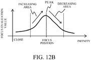
- the peak of the focus evaluation value in the range searched in step S1101 is detected, and it is determined that it has the mountain and that focusing is possible if there are both an area where the focus evaluation value decreases and an area where the focus evaluation value increases in the vicinity of the peak.
- FIG. 12B illustrates an example of the increasing area and the decreasing area. In FIG. 12B , the horizontal axis represents the focus position, and the vertical axis represents the focus evaluation value.
- step S1104 of FIG. 11 When it is determined in step S1104 of FIG. 11 that focusing is not possible, the process returns to step S1103 and the peak detector 14 determines whether focusing is possible in an area (focus evaluation area) of the next priority. On the other hand, when it is determined in step S1104 that focusing is possible, the process proceeds to step S1105.
- the focus evaluation value of the B frame having the highest priority includes both the increasing area and the decreasing area near the peak. For this reason, the B frame is evaluated as being focusable, and focusing is performed by using the B frame.
- FIG. 13 illustrates an example of the correspondence relationship between the focus evaluation value and the focus position in the A frame to the E frame when the focus evaluation value in the B frame varies.
- the horizontal axis represents the focus position
- the vertical axis represents the focus evaluation value.
- the focus evaluation value of the B frame includes only an increasing area (that is, it does not include a decreasing area)
- focusing is performed by using the E frame having the next highest priority.
- the autofocus (AF) process is performed using the area closest to the in-focus position, so that more robust temperature correction can be performed.
- step S1105 of FIG. 11 the focus operation instruction unit 13 moves the focus position to the peak position of the focus evaluation value of the area determined that focusing is possible in step S1104 to perform focusing.
- the focus operation instruction unit 13 moves the focus position to the peak position of the focus evaluation value of the area determined that focusing is possible in step S1104 to perform focusing.
- the area which is determined (evaluated) that focusing is impossible continuously a predetermined number of times in the focusing process may include an object that did not exist at the time of setting the priorities (for example, when the car is parked). In such a case, it is preferable to reset the area so that its priority is low. Thus, the number of times of area selection in the focusing process can be reduced.
- the temperature correction is described as an example, the correction target is not limited to temperature and may be humidity or brightness.
- the control apparatus includes the divider (area setter 7), the calculator (the evaluation value generator 8), and the focus adjuster (focus search unit 10).
- the divider divides the image (captured image, or display image) into the plurality of areas (evaluation areas).
- the calculator calculates the evaluation value (focus evaluation value, or AF evaluation value) of each of the plurality of areas.
- the focus adjuster performs focusing based on the evaluation value of each of the plurality of areas.
- the control apparatus includes the memory (evaluation value memory 9) that stores the evaluation value of each of the plurality of areas.
- the focus adjuster performs the focusing so as to maintain the relationship of the evaluation values of the plurality of areas stored in the memory. More preferably, the focus adjuster performs the focusing so as to maintain the magnitude relationship of the evaluation values of the plurality of areas stored in the memory. Preferably, the focus adjuster performs the focusing based on a ratio of the evaluation values of the plurality of areas stored in the memory.
- the focus adjuster performs the focusing so as to maintain the ratio of the evaluation values (that is, so that a variation of the ratio is not greater than a predetermined variation, and more preferably, so that the ratios are coincident with each other).
- the memory stores the evaluation values of a predetermined number of areas having relatively high evaluation values among the plurality of areas divided by the divider.
- the memory stores an evaluation value of an area having an evaluation value not less than a predetermined value among the plurality of areas divided by the divider.
- the control apparatus includes the detector (for example, temperature sensor 11) that detects a change of the state (environment).
- the focus adjuster performs the focusing when the detector detects the change of the state. More preferably, the detector detects at least one of temperature, brightness, and humidity.
- the memory updates the evaluation value (stores again the evaluation value) of each of the plurality of areas when a variation of the state is not greater than a predetermined variation and a relationship of the evaluation values is changed (that is, when the magnitude relationship of the evaluation values is changed or the ratio of the evaluation values is changed by not less than a predetermined ratio).
- the focus adjuster performs the focusing again based on the evaluation value acquired after performing the focusing and the evaluation value stored in the memory.
- the focus adjuster repeats the focusing based on the evaluation value acquired after performing the focusing and the evaluation value stored in the memory until a predetermined condition (that is, a condition relating to the magnitude relationship of the evaluation values or the change of the ratio) is satisfied.
- the focus adjuster stops the focusing when the number of times of the focusing exceeds the predetermined number of times.
- the control apparatus includes the peak detector 14 that detects a peak position of the evaluation value, and the priority setter 15 that sets priorities in the plurality of areas. The focus adjuster selects an area (focus evaluation area) where the focusing is to be performed based on the priorities.
- FIG. 14 is a block diagram illustrating a configuration example of an information processing apparatus 1401.
- the information processing apparatus 1401 is, for example, a personal computer connected to an image capturing apparatus 1501 via a general-purpose interface 1406.
- the information processing apparatus 1401 includes a CPU 1402, a ROM 1403, a RAM 1404, an external storage device 1405, and the general-purpose interface 1406.
- the CPU 1402 controls the overall operation of an entire of the image capturing system using the input data and computer programs stored in the ROM 1403 or the RAM 1404. While the case where the CPU 1402 controls the entire of the information processing apparatus 1401 is described in this embodiment as an example, the entire of the information processing apparatus 1401 may be controlled by sharing processing with a plurality of hardware.
- the RAM 1404 includes a memory area that temporarily stores computer programs and data read from the external storage device 1405 and data received from an external device via the general-purpose interface 1406.
- the RAM 1404 is used as a memory area used by the CPU 1402 to execute various types of processing or a memory area used when the CPU 1402 performs processing. That is, the RAM 1404 can appropriately provide various memory areas.
- the ROM 1403 stores setting parameters for setting each unit in the information processing apparatus, a boot program, and the like.
- the external storage device 1405 is a storage device that stores various data, various information, and the like necessary for the CPU 1402 to execute various processes, and is, for example, an HDD or the like.
- the general-purpose interface 1406 is an interface for communicating with the external device (the image capturing apparatus), and is, for example, a USB interface or the like.
- the image capturing apparatus of each embodiment performs focusing using the relationship of evaluation values of a plurality of areas in a captured image (captured screen). Therefore, according to each embodiment, it is possible to provide a control apparatus, an image capturing apparatus, a control method, a program, and a non-transitory computer-readable storage medium which are capable of acquiring an image in which an intended object is in focus even when an image capturing state is changed.
- Embodiment(s) of the present invention can also be realized by a computer of a system or apparatus that reads out and executes computer executable instructions (e.g., one or more programs) recorded on a storage medium (which may also be referred to more fully as a 'non-transitory computer-readable storage medium') to perform the functions of one or more of the above-described embodiment(s) and/or that includes one or more circuits (e.g., application specific integrated circuit (ASIC)) for performing the functions of one or more of the above-described embodiment(s), and by a method performed by the computer of the system or apparatus by, for example, reading out and executing the computer executable instructions from the storage medium to perform the functions of one or more of the above-described embodiment(s) and/or controlling the one or more circuits to perform the functions of one or more of the above-described embodiment(s).
- computer executable instructions e.g., one or more programs
- a storage medium which may also be referred to more fully as
- the computer may comprise one or more processors (e.g., central processing unit (CPU), micro processing unit (MPU)) and may include a network of separate computers or separate processors to read out and execute the computer executable instructions.
- the computer executable instructions may be provided to the computer, for example, from a network or the storage medium.
- the storage medium may include, for example, one or more of a hard disk, a random-access memory (RAM), a read only memory (ROM), a storage of distributed computing systems, an optical disk (such as a compact disc (CD), digital versatile disc (DVD), or Blu-ray Disc (BD)TM), a flash memory device, a memory card, and the like.
Landscapes
- Physics & Mathematics (AREA)
- Engineering & Computer Science (AREA)
- Multimedia (AREA)
- Signal Processing (AREA)
- General Physics & Mathematics (AREA)
- Optics & Photonics (AREA)
- Computer Vision & Pattern Recognition (AREA)
- Automatic Focus Adjustment (AREA)
- Studio Devices (AREA)
- Focusing (AREA)
Abstract
Description
- The present invention relates to an image capturing apparatus, and more particularly to an image capturing apparatus that captures an image while fixing a focus position with manual focusing (MF).
- Conventionally, for an object that is difficult to be focused by auto focus (AF), image capturing may be performed while fixing a focus position by manual focus (MF). On the other hand, the focus position changes depending on a change in environment (image capturing state) such as temperature and humidity. For this reason, when the environment changes, there is a possibility that the image capturing cannot be performed while focusing on an intended object.
- If the environment changes while an image is being captured by MF, for example, the image can be refocused by AF. However, in this case, depending on a frame position of AF or an object position, there is a possibility that an object different from the intended object may be in focus.
FIG. 1 is an image focused on a metronome in front. If focusing is performed by AF when the focus is shifted due to the change in the environment from the state of the image illustrated inFIG. 1 , there is a possibility that a back chart will be in focus as illustrated inFIG. 2 . In order to avoid such a situation, Japanese Patent Laid-Open No.2009-103912 - However, in the image capturing apparatus disclosed in Japanese Patent Laid-Open No.
2009-103912 - The present invention provides a control apparatus, an image capturing apparatus, a control method, a program, and a storage medium which are capable of acquiring an image in which an intended object is in focus even when an image capturing state is changed.
- The present invention in its first aspect provides a control apparatus as specified in
claims 1 to 13. - The present invention in its second aspect provides an image capturing apparatus as specified in
claim 14. - The present invention in its third aspect provides a control method as specified in
claim 15. - The present invention in its fourth aspect provides a program as specified in claim 16.
- The present invention in its fifth aspect provides a storage medium as specified in claim 17.
- Further features of the present invention will become apparent from the following description of exemplary embodiments with reference to the attached drawings.
-
-
FIG. 1 is a reference view of an image focused on a front side. -
FIG. 2 is a reference view of an image focused on a back side. -
FIG. 3 is a block diagram of an image capturing apparatus in a first embodiment. -
FIG. 4 is a flowchart illustrating a focusing process in the first embodiment. -
FIG. 5 is a flowchart illustrating the focusing process in the first embodiment. -
FIG. 6 is a block diagram of an image capturing apparatus in a second embodiment. -
FIG. 7 is a flowchart illustrating a priority setting process of an AF evaluation area in the second embodiment. -
FIG. 8 is an explanatory diagram of the AF evaluation area in the second embodiment. -
FIG. 9 is an explanatory diagram of a focus evaluation value in the second embodiment. -
FIGs. 10A to 10C are setting examples of the AF evaluation area in the second embodiment. -
FIG. 11 is a flowchart of a focusing process in the second embodiment. -
FIGs. 12 A and12B are explanatory diagrams of the focus evaluation value in the focusing process in the second embodiment. -
FIG. 13 is an explanatory diagram of the focus evaluation value in the focusing process in the second embodiment. -
FIG. 14 is a block diagram of an information processing apparatus in each embodiment. - Exemplary embodiments of the present invention will be described below with reference to the accompanied drawings.
- First, referring to
FIG. 3 , the configuration of an image capturing apparatus in a first embodiment of the present invention will be described.FIG. 3 is a block diagram of animage capturing apparatus 100 in this embodiment. - A lens unit (image capturing optical system) 1 is used to adjust a focal length or a focus position. The
lens unit 1 includes an objective lens 1-1, anaperture stop 2, and a focus lens 1-2 that are arranged in a direction along an optical axis OA. Animage sensor 3 receives light transmitted through thelens unit 1 to output an image signal. That is, theimage sensor 3 performs photoelectric conversion on an optical image (object image) formed via thelens unit 1 to output the image signal. AnAD converter 4 performs AD conversion on the image signal (analog signal) output from theimage sensor 3 to be converted into a digital signal. The digital signal output from theAD converter 4 is input to animage processor 5. Theimage processor 5 performs image processing such as demosaicing, development processing, gamma processing, and sharpness processing on the digital signal to output image data. Anencoder 6 compresses the image data output from theimage processor 5 into JPEG or H.264 to be output to an external apparatus. - An area setter (divider) 7 divides a captured image (image signal output from the image processor 5) into a plurality of areas. The image signal for area division may be either RGB before development or YCrCb after development. An evaluation value generator (calculator) 8 generates (calculates) an evaluation value (focus evaluation value, or AF evaluation value) for each of the areas divided by the area setter 7. The focus evaluation value is a contrast of the image signal in each area, and a peak position of the contrast corresponds to an in-focus position.
- An evaluation value memory (memory) 9 stores a plurality of areas with high focus evaluation values among the focus evaluation values output from the
evaluation value generator 8. The area in which the focus evaluation value is to be stored is an area in which a plurality of objects exist and areas having high focus evaluation values can be selected by the predetermined number from the higher one. Alternatively, one or a plurality of focus evaluation values that are not less than a predetermined threshold value may be stored instead of being determined by the number. - A focus search unit (focus adjuster) 10 uses a current focus evaluation value for each area generated by the
evaluation value generator 8 and the focus evaluation value stored in theevaluation value memory 9 to perform focusing (focus adjustment). Thefocus search unit 10 calculates a local peak position based on the magnitude relationship between the focus evaluation values of the plurality of areas stored in theevaluation value memory 9 and the focus evaluation values of the plurality of areas generated by theevaluation value generator 8 to perform the focusing. Alternatively, thefocus search unit 10 may perform control such that a ratio of the focus evaluation values of the plurality of areas generated by theevaluation value generator 8 approaches a ratio of the plurality of focus evaluation values stored in the evaluation value memory 9 (that is, such that the ratio of the focus evaluation values of the plurality of areas generated by theevaluation value generator 8 is within a predetermined range, or preferably coincident with the ratio of the plurality of focus evaluation values stored in the evaluation value memory 9). - A temperature sensor (detector) 11 detects the temperature of the outside air or the internal temperature of the
image capturing apparatus 100. A focussearch restart unit 12 instructs thefocus search unit 10 to perform focusing in accordance with changes in thetemperature sensor 11, brightness Y obtained from theimage processor 5, a humidity sensor (not illustrated), or the like. A focusoperation instruction unit 13 instructs the focus lens 1-2 to perform focusing or manual focus operation according to a user's instruction or the like to drive the focus lens 1-2. The focusoperation instruction unit 13 is a focus position fixing unit that fixes the focus position. Theevaluation value memory 9 stores a focus evaluation value in the focus operation. - Next, referring to
FIG. 4 , the focusing process (focus adjustment) in this embodiment will be described.FIG. 4 is a flowchart of the focusing process, and it illustrates a method of focusing in a range in which the magnitude relationship of the focus evaluation values stored in theevaluation value memory 9 is maintained. Each step inFIG. 4 is mainly performed by theevaluation value generator 8, theevaluation value memory 9, or thefocus search unit 10. - First, in step S401, the
evaluation value generator 8 calculates (generates) a focus evaluation value for each area (area of the captured image) in a screen (captured image, or display image) set by the area setter 7. Subsequently, in step S402, theevaluation value memory 9 selects and stores a plurality (predetermined number) of areas having high focus evaluation values among the focus evaluation values generated by theevaluation value generator 8. Subsequently, in step S403, thefocus search unit 10 performs a focus search within a range in which the magnitude relationship between the plurality of focus evaluation values stored in theevaluation value memory 9 is maintained. That is, thefocus search unit 10 performs focusing while maintaining the magnitude relationship between the focus evaluation value selected from theevaluation value memory 9 and the current focus evaluation value, and calculates a local peak position. - Subsequently, in step S404, the
focus search unit 10 determines whether the magnitude relationship between the focus evaluation values of the plurality of areas stored in theevaluation value memory 9 is maintained after focusing. That is, thefocus search unit 10 determines whether the magnitude relationship of the focus evaluation values of the plurality of areas after focusing is the same as the magnitude relationship of the focus evaluation values of the plurality of areas stored in theevaluation value memory 9. When the magnitude relationship of the focus evaluation values stored in theevaluation value memory 9 is maintained, this flow (focus search operation) is ended. On the other hand, when the magnitude relationship of the focus evaluation values stored in theevaluation value memory 9 is not maintained (that is, when the magnitude relationship of the focus evaluation values changes), the process returns to step S403 and thefocus search unit 10 performs focusing again. When the magnitude relationship of the focus evaluation values stored in theevaluation value memory 9 cannot be maintained even if the process is repeated a predetermined number of times or more, thefocus search unit 10 determines that focusing cannot be performed, and the process may return to S401 or step S402. - Next, referring to
FIG. 5 , the focusing process (focus adjustment) in this embodiment will be described.FIG. 5 is a flowchart of the focusing process, and it illustrates a method of performing focusing while maintaining a ratio of the focus evaluation values stored in theevaluation value memory 9. Each step inFIG. 5 is mainly performed by theevaluation value generator 8, theevaluation value memory 9, or thefocus search unit 10. - First, in step S501, the
evaluation value generator 8 calculates (generates) a focus evaluation value for each area (area of the captured image) in a screen (captured image, or display image) set by the area setter 7. Subsequently, in step S502, theevaluation value memory 9 selects and stores a plurality (predetermined number) of areas having high focus evaluation values among the focus evaluation values generated by theevaluation value generator 8. Subsequently, in step S503, thefocus search unit 10 calculates the ratio of the focus evaluation values of the plurality of areas selected from theevaluation value memory 9. - Subsequently, in step S504, the
focus search unit 10 performs focusing so that the focus evaluation value becomes the ratio of the focus evaluation values calculated in step S503. That is, thefocus search unit 10 performs focusing so that the ratio of the focus evaluation values after focusing and the ratio of the focus evaluation values calculated in step S503 fall within a predetermined range (preferably, so that they coincide with each other). When the focus evaluation value for each of the areas generated by theevaluation value generator 8 changes without a change in temperature or humidity detected by thetemperature sensor 11 or the humidity sensor after focusing, thefocus search unit 10 may determine that an object has changed, such as movement of a vehicle. In this case, thefocus search unit 10 updates the value stored in theevaluation value memory 9. - Next, a second embodiment of the present invention will be described. In the first embodiment, when the moving object enters any of areas used for focusing and the state changes, and the magnitude relationship of the focus evaluation values largely breaks, sufficient effects may not be obtained. Therefore, in this embodiment, priorities are given to a plurality of areas, and areas to be used for focusing are selected based on the priorities in accordance with changes in the state of the object. In this embodiment, the same components as those in the first embodiment are denoted by the same reference numerals, and detailed descriptions thereof will be omitted.
- First, referring to
FIG. 6 , the configuration of an image capturing apparatus in this embodiment will be described.FIG. 6 is a block diagram of animage capturing apparatus 100a in this embodiment. Theevaluation value memory 9 acquires and stores the focus evaluation value of the area divided by the area setter 7 from theevaluation value generator 8. Unlike the first embodiment, theevaluation value memory 9 stores the focus evaluation value and the focus position acquired from thefocus search unit 10 or the focusoperation instruction unit 13 in association with each other. Apeak detector 14 detects a peak position of the focus evaluation value stored in theevaluation value memory 9 and evaluates whether focusing is possible. Apriority setter 15 calculates a distance between the peak position detected by thepeak detector 14 and the current focus position, and sets the priority (order of priority) used for focusing on each area. - Next, referring to
FIGs. 7 to 10C , a priority setting process of areas (AF evaluation areas) in this embodiment will be described.FIG. 7 is a flowchart illustrating the priority setting process of the AF evaluation areas. Each step inFIG. 7 is mainly performed by theevaluation value memory 9, thepeak detector 14, or thepriority setter 15.FIG. 8 is an explanatory diagram of the AF evaluation areas.FIG. 9 is an explanatory diagram of focus evaluation values.FIGs. 10A to 10C are setting examples of the AF evaluation areas. The flow ofFIG. 7 is started by an MF operation or an AF operation by the user. InFIG. 7 , in order to simplify descriptions, five areas (A frame to E frame) in the evaluation areas illustrated inFIG. 8 will be described. - First, in step S701 of
FIG. 7 , theevaluation value memory 9 acquires the focus position and the focus evaluation value of each area from the focusoperation instruction unit 13 and theevaluation value generator 8, respectively, and stores the correspondence relationship.FIG. 9 is an example of the correspondence relationship between the focus evaluation value and the focus position in the five areas (A frame to E frame) illustrated inFIG. 8 . InFIG. 9 , the horizontal axis represents the focus position, and the vertical axis represents the focus evaluation value. - Subsequently, in step S702, the
peak detector 14 determines whether the drive (focus drive) of the focus lens 1-2 is completed. When the focus drive is not completed, the process returns to step S701. On the other hand, when the focus drive is completed, the process proceeds to step S703. In the case of the AF control, the determination process of step S702 may be performed based on whether the AF operation is completed. In the case of the MF operation by the user, thepeak detector 14 can determine whether a predetermined time has elapsed since the last operation. Alternatively, thepeak detector 14 may be provided with a button that notifies the completion of the MF operation on the screen to perform the determination in response to the press of the button by the user. Alternatively, thepeak detector 14 may acquire information on whether the drive motor is operating from thelens unit 1 to perform the determination. - Subsequently, in step S703, the
peak detector 14 acquires the focus evaluation value of each area (evaluation area) from theevaluation value memory 9, and detects the peak position. The peak position can be detected by using known techniques. For example, the position of the maximum value of the focus evaluation value can be simply used as the peak position. Alternatively, the position of the maximum value among the focus evaluation values exceeding a predetermined threshold value may be used as the peak position. - Subsequently, in step S704, the
priority setter 15 calculates the distance between the focus position last set by the user and the peak position of each area detected in step S703. This distance is used to set the priority in the subsequent step S705. Subsequently, in step S705, thepriority setter 15 sets priorities (orders of priorities) for the respective areas in order from the closest distance calculated in step S704. That is, thepriority setter 15 sets the priority for the area to be higher as the area is closer to the in-focus state. In the example illustrated inFIG. 9 , the priority (order of priority) is in order of the B frame, the E frame, the A frame, the C frame, and the D frame. - In step S705 of
FIG. 7 , it is not necessary to set priorities in all the areas. For example, the priorities may be set only for the area where the distance calculated in step S704 is not greater than a predetermined threshold value. This makes it possible to suppress the focus shift to an object at a distance. - When a plurality of areas having the same peak position exist, it is preferable to set an area having a high focus evaluation value as a high priority or to set an area having a sharp peak in the focus evaluation value as a high priority. Alternatively, the same priority may be set to areas, and an area used for focusing may be appropriately selected according to the distance to the peak position or the like in the focusing process described below.
- In this embodiment, the plurality of evaluation areas can be set so as to divide the area on the screen as illustrated in
FIG. 10A . Alternatively, the plurality of evaluation areas may be discretely set to an arbitrary position on the screen as illustrated inFIG. 10B , or they may be set to have overlapping areas as illustrated inFIG. 10C . - Next, referring to
FIG. 11 , a focusing process (focus adjustment) in this embodiment will be described.FIG. 11 is a flowchart of the focusing process. Each step inFIG. 11 is mainly performed by theevaluation value generator 8, theevaluation value memory 9, or thefocus search unit 10 at fixed time intervals or every time the temperature changes by a fixed amount. - First, in step S1101, the
focus search unit 10 performs a focus search of a predetermined width (predetermined focus search width). The predetermined width is determined, for example, such that the amount of focus movement at the time of a temperature change measured in advance is contained. At the same time, theevaluation value memory 9 stores the correspondence relationship between the focus position and the focus evaluation value of each area.FIG. 12A is an example of the correspondence relationship between the focus evaluation value and the focus position in the five areas illustrated inFIG. 8 (A frame to E frame). InFIG 12A , the horizontal axis represents the focus position, and the vertical axis represents the focus evaluation value. - Subsequently, in step S1102 of
FIG. 11 , thefocus search unit 10 acquires, from thepriority setter 15, the priority (order of priority) set to each area. Subsequently, in step S1103, thepeak detector 14 selects an area (focus evaluation area) to be used in the evaluation as to whether focusing is possible in the subsequent step S1104 based on the priority acquired in step S1101. - Subsequently, in step S1104, the
peak detector 14 determines whether focusing is possible in the focusing evaluation area set (selected) in step S1103. This determination is performed by detecting whether the focus evaluation value has a "mountain". In this embodiment, the peak of the focus evaluation value in the range searched in step S1101 is detected, and it is determined that it has the mountain and that focusing is possible if there are both an area where the focus evaluation value decreases and an area where the focus evaluation value increases in the vicinity of the peak.FIG. 12B illustrates an example of the increasing area and the decreasing area. InFIG. 12B , the horizontal axis represents the focus position, and the vertical axis represents the focus evaluation value. - When it is determined in step S1104 of
FIG. 11 that focusing is not possible, the process returns to step S1103 and thepeak detector 14 determines whether focusing is possible in an area (focus evaluation area) of the next priority. On the other hand, when it is determined in step S1104 that focusing is possible, the process proceeds to step S1105. In the case of the example illustrated inFIG. 12A , the focus evaluation value of the B frame having the highest priority (order of priority) includes both the increasing area and the decreasing area near the peak. For this reason, the B frame is evaluated as being focusable, and focusing is performed by using the B frame. - On the other hand, when a moving object enters the B frame and thus objects are changed, the focus evaluation value varies, for example, as the example illustrated in
FIG. 13. FIG. 13 illustrates an example of the correspondence relationship between the focus evaluation value and the focus position in the A frame to the E frame when the focus evaluation value in the B frame varies. InFIG. 13 , the horizontal axis represents the focus position, and the vertical axis represents the focus evaluation value. In this case, since the focus evaluation value of the B frame includes only an increasing area (that is, it does not include a decreasing area), it is determined in step S1104 that focusing is impossible. As a result, focusing is performed by using the E frame having the next highest priority. Thus, even when an obstacle such as a moving object is included in the evaluation area, the autofocus (AF) process is performed using the area closest to the in-focus position, so that more robust temperature correction can be performed. - Subsequently, in step S1105 of
FIG. 11 , the focusoperation instruction unit 13 moves the focus position to the peak position of the focus evaluation value of the area determined that focusing is possible in step S1104 to perform focusing. In a situation where the object is dark at night, etc., it may be determined that focusing for all the areas where the priorities are set is impossible and temperature correction by the AF process may not be performed. In this case, it is preferable to measure the focus movement for the temperature variation in advance, and move the focus position by a fixed amount derived from the measured value. Thereby, even in a situation where the temperature correction by the AF process cannot be performed, a certain degree of a correction effect can be obtained. If there is no measured value, the focus position may be returned to the focus position before the focus search in step S1102. - Among the areas where the priorities are given, the area which is determined (evaluated) that focusing is impossible continuously a predetermined number of times in the focusing process may include an object that did not exist at the time of setting the priorities (for example, when the car is parked). In such a case, it is preferable to reset the area so that its priority is low. Thus, the number of times of area selection in the focusing process can be reduced. In this embodiment, while the temperature correction is described as an example, the correction target is not limited to temperature and may be humidity or brightness.
- As described above, in each embodiment, the control apparatus (
image capturing apparatus - Preferably, the control apparatus includes the memory (evaluation value memory 9) that stores the evaluation value of each of the plurality of areas. The focus adjuster performs the focusing so as to maintain the relationship of the evaluation values of the plurality of areas stored in the memory. More preferably, the focus adjuster performs the focusing so as to maintain the magnitude relationship of the evaluation values of the plurality of areas stored in the memory. Preferably, the focus adjuster performs the focusing based on a ratio of the evaluation values of the plurality of areas stored in the memory. More preferably, the focus adjuster performs the focusing so as to maintain the ratio of the evaluation values (that is, so that a variation of the ratio is not greater than a predetermined variation, and more preferably, so that the ratios are coincident with each other). Preferably, the memory stores the evaluation values of a predetermined number of areas having relatively high evaluation values among the plurality of areas divided by the divider. Preferably, the memory stores an evaluation value of an area having an evaluation value not less than a predetermined value among the plurality of areas divided by the divider.
- Preferably, the control apparatus includes the detector (for example, temperature sensor 11) that detects a change of the state (environment). The focus adjuster performs the focusing when the detector detects the change of the state. More preferably, the detector detects at least one of temperature, brightness, and humidity. Preferably, the memory updates the evaluation value (stores again the evaluation value) of each of the plurality of areas when a variation of the state is not greater than a predetermined variation and a relationship of the evaluation values is changed (that is, when the magnitude relationship of the evaluation values is changed or the ratio of the evaluation values is changed by not less than a predetermined ratio).
- Preferably, the focus adjuster performs the focusing again based on the evaluation value acquired after performing the focusing and the evaluation value stored in the memory. The focus adjuster repeats the focusing based on the evaluation value acquired after performing the focusing and the evaluation value stored in the memory until a predetermined condition (that is, a condition relating to the magnitude relationship of the evaluation values or the change of the ratio) is satisfied. Then, the focus adjuster stops the focusing when the number of times of the focusing exceeds the predetermined number of times. Preferably, the control apparatus includes the
peak detector 14 that detects a peak position of the evaluation value, and thepriority setter 15 that sets priorities in the plurality of areas. The focus adjuster selects an area (focus evaluation area) where the focusing is to be performed based on the priorities. - In the embodiments described above, the case where the present invention is realized as a dedicated processing circuit incorporated in the image capturing apparatus is described as an example. However, the present invention can be realized even when the circuit configuration is not necessarily built in the image capturing apparatus. For example, the present invention may be realized using an information processing apparatus independent of the image capturing apparatus by software (computer program).
FIG. 14 is a block diagram illustrating a configuration example of aninformation processing apparatus 1401. Theinformation processing apparatus 1401 is, for example, a personal computer connected to animage capturing apparatus 1501 via a general-purpose interface 1406. - The
information processing apparatus 1401 includes aCPU 1402, aROM 1403, aRAM 1404, anexternal storage device 1405, and the general-purpose interface 1406. TheCPU 1402 controls the overall operation of an entire of the image capturing system using the input data and computer programs stored in theROM 1403 or theRAM 1404. While the case where theCPU 1402 controls the entire of theinformation processing apparatus 1401 is described in this embodiment as an example, the entire of theinformation processing apparatus 1401 may be controlled by sharing processing with a plurality of hardware. - The
RAM 1404 includes a memory area that temporarily stores computer programs and data read from theexternal storage device 1405 and data received from an external device via the general-purpose interface 1406. TheRAM 1404 is used as a memory area used by theCPU 1402 to execute various types of processing or a memory area used when theCPU 1402 performs processing. That is, theRAM 1404 can appropriately provide various memory areas. TheROM 1403 stores setting parameters for setting each unit in the information processing apparatus, a boot program, and the like. Theexternal storage device 1405 is a storage device that stores various data, various information, and the like necessary for theCPU 1402 to execute various processes, and is, for example, an HDD or the like. The general-purpose interface 1406 is an interface for communicating with the external device (the image capturing apparatus), and is, for example, a USB interface or the like. - The image capturing apparatus of each embodiment performs focusing using the relationship of evaluation values of a plurality of areas in a captured image (captured screen). Therefore, according to each embodiment, it is possible to provide a control apparatus, an image capturing apparatus, a control method, a program, and a non-transitory computer-readable storage medium which are capable of acquiring an image in which an intended object is in focus even when an image capturing state is changed.
- Embodiment(s) of the present invention can also be realized by a computer of a system or apparatus that reads out and executes computer executable instructions (e.g., one or more programs) recorded on a storage medium (which may also be referred to more fully as a 'non-transitory computer-readable storage medium') to perform the functions of one or more of the above-described embodiment(s) and/or that includes one or more circuits (e.g., application specific integrated circuit (ASIC)) for performing the functions of one or more of the above-described embodiment(s), and by a method performed by the computer of the system or apparatus by, for example, reading out and executing the computer executable instructions from the storage medium to perform the functions of one or more of the above-described embodiment(s) and/or controlling the one or more circuits to perform the functions of one or more of the above-described embodiment(s). The computer may comprise one or more processors (e.g., central processing unit (CPU), micro processing unit (MPU)) and may include a network of separate computers or separate processors to read out and execute the computer executable instructions. The computer executable instructions may be provided to the computer, for example, from a network or the storage medium. The storage medium may include, for example, one or more of a hard disk, a random-access memory (RAM), a read only memory (ROM), a storage of distributed computing systems, an optical disk (such as a compact disc (CD), digital versatile disc (DVD), or Blu-ray Disc (BD)™), a flash memory device, a memory card, and the like.
- While the present invention has been described with reference to exemplary embodiments, it is to be understood that the invention is not limited to the disclosed exemplary embodiments. The scope of the following claims is to be accorded the broadest interpretation so as to encompass all such modifications and equivalent structures and functions.
Claims (17)
- A control apparatus (100) comprising:a divider (7) configured to divide an image into a plurality of areas;a calculator (8) configured to calculate an evaluation value of each of the plurality of areas; anda focus adjuster (10) configured to perform focusing based on the evaluation value of each of the plurality of areas.
- The control apparatus according to claim 1, further comprising a memory configured to store the evaluation value of each of the plurality of areas,
wherein the focus adjuster is configured to perform the focusing so as to maintain a relationship of the evaluation values of the plurality of areas stored in the memory. - The control apparatus according to claim 2, wherein the focus adjuster is configured to perform the focusing so as to maintain a magnitude relationship of the evaluation values of the plurality of areas stored in the memory.
- The control apparatus according to claim 2, wherein the focus adjuster is configured to perform the focusing based on a ratio of the evaluation values of the plurality of areas stored in the memory.
- The control apparatus according to claim 4, wherein the focus adjuster is configured to perform the focusing so as to maintain the ratio of the evaluation values.
- The control apparatus according to any one of claims 2 to 5, wherein the memory is configured to store evaluation values of a predetermined number of areas having relatively high evaluation values among the plurality of areas divided by the divider.
- The control apparatus according to any one of claims 2 to 5, wherein the memory is configured to store evaluation values of areas having the evaluation values not less than a predetermined value among the plurality of areas divided by the divider.
- The control apparatus according to any one of claims 2 to 7, further comprising a detector configured to detect a change of a state,
wherein the focus adjuster is configured to perform the focusing when the detector detects the change of the state. - The control apparatus according to claim 8, wherein the detector is configured to detect at least one of temperature, brightness, or humidity.
- The control apparatus according to claim 8 or 9, wherein the memory is configured to update the evaluation value of each of the plurality of areas when a variation of the state is not greater than a predetermined variation and a relationship of the evaluation values is changed.
- The control apparatus according to any one of claims 2 to 10, wherein the focus adjuster is configured to perform the focusing again based on an evaluation value acquired after performing the focusing and the evaluation value stored in the memory.
- The control apparatus according to claim 11, wherein the focus adjuster is configured to:repeat the focusing based on the evaluation value acquired after performing the focusing and the evaluation value stored in the memory until a predetermined condition is satisfied, andstop the focusing when a number of times of the focusing exceeds a predetermined number of times.
- The control apparatus according to any one of claims 1 to 12, further comprising:a peak detector configured to detect a peak position of the evaluation value; anda priority setter configured to set priorities in the plurality of areas,wherein the focus adjuster is configured to select an area where the focusing is to be performed based on the priorities.
- An image capturing apparatus comprising:an image sensor configured to photoelectrically convert an optical image formed via an image capturing optical system; andthe control apparatus according to any one of claims 1 to 13.
- A control method comprising:dividing an image into a plurality of areas;calculating an evaluation value of each of the plurality of areas; andperforming focusing based on the evaluation value of each of the plurality of areas.
- A program which causes a computer to execute a control method according to claim 15.
- A storage medium which stores a program according to claim 16.
Applications Claiming Priority (1)
| Application Number | Priority Date | Filing Date | Title |
|---|---|---|---|
| JP2018177576A JP7289621B2 (en) | 2018-09-21 | 2018-09-21 | Control device, imaging device, control method, and program |
Publications (1)
| Publication Number | Publication Date |
|---|---|
| EP3627826A1 true EP3627826A1 (en) | 2020-03-25 |
Family
ID=67997980
Family Applications (1)
| Application Number | Title | Priority Date | Filing Date |
|---|---|---|---|
| EP19197799.0A Withdrawn EP3627826A1 (en) | 2018-09-21 | 2019-09-17 | Control apparatus, image capturing apparatus, control method, program, and storage medium |
Country Status (4)
| Country | Link |
|---|---|
| US (1) | US11172118B2 (en) |
| EP (1) | EP3627826A1 (en) |
| JP (1) | JP7289621B2 (en) |
| CN (1) | CN110941076B (en) |
Families Citing this family (10)
| Publication number | Priority date | Publication date | Assignee | Title |
|---|---|---|---|---|
| KR102510704B1 (en) * | 2018-10-30 | 2023-03-16 | 캐논 가부시끼가이샤 | Imaging apparatus |
| US11089197B1 (en) | 2020-01-27 | 2021-08-10 | Aptiv Technologies Limited | Camera with phased metalens |
| US11089188B1 (en) | 2020-11-02 | 2021-08-10 | Aptiv Technologies Limited | Phased metalens for adjusting a focus of an image |
| KR20230033994A (en) | 2021-09-02 | 2023-03-09 | 삼성전자주식회사 | Electronic device including a plurality of cameras and operating method thereof |
| US12140417B2 (en) | 2021-12-22 | 2024-11-12 | Aptiv Technologies AG | Actively select lenses for camera focus processes |
| US12405525B2 (en) | 2021-12-22 | 2025-09-02 | Aptiv Technologies AG | Actively select lenses for camera focus processes |
| JPWO2023145480A1 (en) * | 2022-01-28 | 2023-08-03 | ||
| KR102772833B1 (en) * | 2022-04-21 | 2025-02-26 | 주식회사 케이랩 | Apparatus and method for measuring a focal length |
| US12455427B2 (en) | 2022-05-03 | 2025-10-28 | Aptiv Technologies AG | Camera focusing including lens centration estimation using variable focal length phased metalens |
| US12449719B2 (en) | 2022-09-06 | 2025-10-21 | Aptiv Technologies AG | Phased metalens depth of focus increase for camera focusing |
Citations (6)
| Publication number | Priority date | Publication date | Assignee | Title |
|---|---|---|---|---|
| US6268885B1 (en) * | 1996-01-31 | 2001-07-31 | Canon Kabushiki Kaisha | Optical apparatus for correcting focus based on temperature and humidity |
| US20010038418A1 (en) * | 1995-06-22 | 2001-11-08 | Hirofumi Suda | Interchangeable lens video camera system |
| US20040201770A1 (en) * | 2003-04-09 | 2004-10-14 | Fuji Photo Film Co., Ltd. | Pickup device for picking up image |
| US20090051805A1 (en) * | 2007-08-23 | 2009-02-26 | Fujifilm Corporation | Focusing apparatus and focusing method |
| JP2009103912A (en) | 2007-10-23 | 2009-05-14 | Olympus Corp | Imaging device |
| US20150189155A1 (en) * | 2013-12-27 | 2015-07-02 | Hitachi Industry & Control Solutions, Ltd. | Focus control apparatus and method |
Family Cites Families (6)
| Publication number | Priority date | Publication date | Assignee | Title |
|---|---|---|---|---|
| JP2000155257A (en) * | 1998-11-19 | 2000-06-06 | Fuji Photo Film Co Ltd | Method and device for autofocusing |
| US7859588B2 (en) | 2007-03-09 | 2010-12-28 | Eastman Kodak Company | Method and apparatus for operating a dual lens camera to augment an image |
| JP2015152742A (en) | 2014-02-13 | 2015-08-24 | キヤノン株式会社 | Imaging device and control method thereof |
| US20150227023A1 (en) * | 2014-02-13 | 2015-08-13 | Canon Kabushiki Kaisha | Focus control apparatus and control method therefor |
| JP6478496B2 (en) * | 2014-07-03 | 2019-03-06 | キヤノン株式会社 | Imaging apparatus and control method thereof |
| JP6866204B2 (en) | 2017-02-02 | 2021-04-28 | キヤノン株式会社 | Focus control device, image pickup device, temperature compensation setting device and focus control method |
-
2018
- 2018-09-21 JP JP2018177576A patent/JP7289621B2/en active Active
-
2019
- 2019-09-13 US US16/569,941 patent/US11172118B2/en active Active
- 2019-09-17 EP EP19197799.0A patent/EP3627826A1/en not_active Withdrawn
- 2019-09-19 CN CN201910889108.3A patent/CN110941076B/en active Active
Patent Citations (6)
| Publication number | Priority date | Publication date | Assignee | Title |
|---|---|---|---|---|
| US20010038418A1 (en) * | 1995-06-22 | 2001-11-08 | Hirofumi Suda | Interchangeable lens video camera system |
| US6268885B1 (en) * | 1996-01-31 | 2001-07-31 | Canon Kabushiki Kaisha | Optical apparatus for correcting focus based on temperature and humidity |
| US20040201770A1 (en) * | 2003-04-09 | 2004-10-14 | Fuji Photo Film Co., Ltd. | Pickup device for picking up image |
| US20090051805A1 (en) * | 2007-08-23 | 2009-02-26 | Fujifilm Corporation | Focusing apparatus and focusing method |
| JP2009103912A (en) | 2007-10-23 | 2009-05-14 | Olympus Corp | Imaging device |
| US20150189155A1 (en) * | 2013-12-27 | 2015-07-02 | Hitachi Industry & Control Solutions, Ltd. | Focus control apparatus and method |
Also Published As
| Publication number | Publication date |
|---|---|
| US11172118B2 (en) | 2021-11-09 |
| CN110941076B (en) | 2022-07-05 |
| US20200099851A1 (en) | 2020-03-26 |
| JP7289621B2 (en) | 2023-06-12 |
| JP2020046637A (en) | 2020-03-26 |
| CN110941076A (en) | 2020-03-31 |
Similar Documents
| Publication | Publication Date | Title |
|---|---|---|
| EP3627826A1 (en) | Control apparatus, image capturing apparatus, control method, program, and storage medium | |
| EP3358386B1 (en) | Focus control apparatus, image capturing apparatus, and focus control method | |
| US11277554B2 (en) | Control apparatus, imaging apparatus, control method, and storage medium | |
| CN103095983A (en) | Image signal processing device | |
| US11240420B2 (en) | Image pickup apparatus, setting apparatus, wavelength acquiring apparatus, and storage medium | |
| EP4509916A2 (en) | Focus control apparatus, image capturing apparatus, and focus control method | |
| US10999491B2 (en) | Control apparatus, image capturing apparatus, control method, and storage medium | |
| US20200228719A1 (en) | Focus control apparatus, imaging apparatus, focus control method, and storage medium | |
| US9781330B2 (en) | Focus detection apparatus and control method for focus detection apparatus | |
| US9742983B2 (en) | Image capturing apparatus with automatic focus adjustment and control method thereof, and storage medium | |
| US9906709B2 (en) | Image pickup apparatus having image pickup element including a plurality of pixels, each pixel including a plurality of photodiodes corresponding to microlens, lens unit to be removably mounted on image pick up apparatus, and methods of controlling image pickup apparatus and lens unit | |
| US10999522B2 (en) | Control apparatus, control method, and computer-readable storage medium | |
| US9781331B2 (en) | Imaging apparatus, and control method thereof | |
| US9609202B2 (en) | Image pickup apparatus and control method with focus adjusting modes | |
| US9591201B2 (en) | AF controller, lens apparatus including the AF controller and image pickup apparatus | |
| US9282234B2 (en) | Focus adjustment apparatus and method, and image capturing apparatus | |
| US11696050B2 (en) | Imaging apparatus, method for controlling imaging apparatus, and storage medium | |
| US11528406B2 (en) | Control apparatus, image pickup apparatus which changes an autofocus operation based on a ratio of a number of low contrast frames to a number of focus detecting frames | |
| US9832364B2 (en) | Automatic focal adjustment apparatus and method of controlling automatic focal adjustment apparatus, and image capture apparatus | |
| US20260044965A1 (en) | Image processing apparatus and method of processing image in which a setting unit sets a tracking target | |
| US12190527B2 (en) | Image processing device, control method thereof, imaging device, and recording medium | |
| US20220400210A1 (en) | Image processing apparatus, image pickup apparatus, image processing method, and recording medium | |
| JP6080619B2 (en) | Focus detection apparatus and method | |
| US20200099842A1 (en) | Image capturing apparatus and control method thereof, and storage medium |
Legal Events
| Date | Code | Title | Description |
|---|---|---|---|
| PUAI | Public reference made under article 153(3) epc to a published international application that has entered the european phase |
Free format text: ORIGINAL CODE: 0009012 |
|
| STAA | Information on the status of an ep patent application or granted ep patent |
Free format text: STATUS: THE APPLICATION HAS BEEN PUBLISHED |
|
| AK | Designated contracting states |
Kind code of ref document: A1 Designated state(s): AL AT BE BG CH CY CZ DE DK EE ES FI FR GB GR HR HU IE IS IT LI LT LU LV MC MK MT NL NO PL PT RO RS SE SI SK SM TR |
|
| AX | Request for extension of the european patent |
Extension state: BA ME |
|
| STAA | Information on the status of an ep patent application or granted ep patent |
Free format text: STATUS: REQUEST FOR EXAMINATION WAS MADE |
|
| 17P | Request for examination filed |
Effective date: 20200925 |
|
| RBV | Designated contracting states (corrected) |
Designated state(s): AL AT BE BG CH CY CZ DE DK EE ES FI FR GB GR HR HU IE IS IT LI LT LU LV MC MK MT NL NO PL PT RO RS SE SI SK SM TR |
|
| STAA | Information on the status of an ep patent application or granted ep patent |
Free format text: STATUS: EXAMINATION IS IN PROGRESS |
|
| 17Q | First examination report despatched |
Effective date: 20201112 |
|
| STAA | Information on the status of an ep patent application or granted ep patent |
Free format text: STATUS: THE APPLICATION HAS BEEN WITHDRAWN |
|
| 18W | Application withdrawn |
Effective date: 20240129 |