EP3627811A1 - Image forming apparatus and image forming system - Google Patents
Image forming apparatus and image forming system Download PDFInfo
- Publication number
- EP3627811A1 EP3627811A1 EP19196426.1A EP19196426A EP3627811A1 EP 3627811 A1 EP3627811 A1 EP 3627811A1 EP 19196426 A EP19196426 A EP 19196426A EP 3627811 A1 EP3627811 A1 EP 3627811A1
- Authority
- EP
- European Patent Office
- Prior art keywords
- user
- image forming
- terminal
- forming apparatus
- installation
- Prior art date
- Legal status (The legal status is an assumption and is not a legal conclusion. Google has not performed a legal analysis and makes no representation as to the accuracy of the status listed.)
- Granted
Links
Images




Classifications
-
- H—ELECTRICITY
- H04—ELECTRIC COMMUNICATION TECHNIQUE
- H04N—PICTORIAL COMMUNICATION, e.g. TELEVISION
- H04N1/00—Scanning, transmission or reproduction of documents or the like, e.g. facsimile transmission; Details thereof
- H04N1/00962—Input arrangements for operating instructions or parameters, e.g. updating internal software
-
- H—ELECTRICITY
- H04—ELECTRIC COMMUNICATION TECHNIQUE
- H04N—PICTORIAL COMMUNICATION, e.g. TELEVISION
- H04N1/00—Scanning, transmission or reproduction of documents or the like, e.g. facsimile transmission; Details thereof
- H04N1/0035—User-machine interface; Control console
- H04N1/00405—Output means
- H04N1/00408—Display of information to the user, e.g. menus
- H04N1/00411—Display of information to the user, e.g. menus the display also being used for user input, e.g. touch screen
-
- G—PHYSICS
- G06—COMPUTING OR CALCULATING; COUNTING
- G06F—ELECTRIC DIGITAL DATA PROCESSING
- G06F3/00—Input arrangements for transferring data to be processed into a form capable of being handled by the computer; Output arrangements for transferring data from processing unit to output unit, e.g. interface arrangements
- G06F3/12—Digital output to print unit, e.g. line printer, chain printer
- G06F3/1201—Dedicated interfaces to print systems
- G06F3/1223—Dedicated interfaces to print systems specifically adapted to use a particular technique
- G06F3/1237—Print job management
- G06F3/1238—Secure printing, e.g. user identification, user rights for device usage, unallowed content, blanking portions or fields of a page, releasing held jobs
-
- G—PHYSICS
- G06—COMPUTING OR CALCULATING; COUNTING
- G06F—ELECTRIC DIGITAL DATA PROCESSING
- G06F21/00—Security arrangements for protecting computers, components thereof, programs or data against unauthorised activity
- G06F21/60—Protecting data
- G06F21/606—Protecting data by securing the transmission between two devices or processes
- G06F21/608—Secure printing
-
- G—PHYSICS
- G06—COMPUTING OR CALCULATING; COUNTING
- G06F—ELECTRIC DIGITAL DATA PROCESSING
- G06F3/00—Input arrangements for transferring data to be processed into a form capable of being handled by the computer; Output arrangements for transferring data from processing unit to output unit, e.g. interface arrangements
- G06F3/12—Digital output to print unit, e.g. line printer, chain printer
- G06F3/1201—Dedicated interfaces to print systems
- G06F3/1202—Dedicated interfaces to print systems specifically adapted to achieve a particular effect
- G06F3/1203—Improving or facilitating administration, e.g. print management
- G06F3/1204—Improving or facilitating administration, e.g. print management resulting in reduced user or operator actions, e.g. presetting, automatic actions, using hardware token storing data
-
- G—PHYSICS
- G06—COMPUTING OR CALCULATING; COUNTING
- G06F—ELECTRIC DIGITAL DATA PROCESSING
- G06F3/00—Input arrangements for transferring data to be processed into a form capable of being handled by the computer; Output arrangements for transferring data from processing unit to output unit, e.g. interface arrangements
- G06F3/12—Digital output to print unit, e.g. line printer, chain printer
- G06F3/1201—Dedicated interfaces to print systems
- G06F3/1223—Dedicated interfaces to print systems specifically adapted to use a particular technique
- G06F3/1224—Client or server resources management
- G06F3/1225—Software update, e.g. print driver, modules, plug-ins, fonts
-
- G—PHYSICS
- G06—COMPUTING OR CALCULATING; COUNTING
- G06F—ELECTRIC DIGITAL DATA PROCESSING
- G06F3/00—Input arrangements for transferring data to be processed into a form capable of being handled by the computer; Output arrangements for transferring data from processing unit to output unit, e.g. interface arrangements
- G06F3/12—Digital output to print unit, e.g. line printer, chain printer
- G06F3/1201—Dedicated interfaces to print systems
- G06F3/1278—Dedicated interfaces to print systems specifically adapted to adopt a particular infrastructure
- G06F3/1285—Remote printer device, e.g. being remote from client or server
-
- G—PHYSICS
- G06—COMPUTING OR CALCULATING; COUNTING
- G06F—ELECTRIC DIGITAL DATA PROCESSING
- G06F3/00—Input arrangements for transferring data to be processed into a form capable of being handled by the computer; Output arrangements for transferring data from processing unit to output unit, e.g. interface arrangements
- G06F3/12—Digital output to print unit, e.g. line printer, chain printer
- G06F3/1201—Dedicated interfaces to print systems
- G06F3/1278—Dedicated interfaces to print systems specifically adapted to adopt a particular infrastructure
- G06F3/1285—Remote printer device, e.g. being remote from client or server
- G06F3/1287—Remote printer device, e.g. being remote from client or server via internet
-
- G—PHYSICS
- G06—COMPUTING OR CALCULATING; COUNTING
- G06F—ELECTRIC DIGITAL DATA PROCESSING
- G06F3/00—Input arrangements for transferring data to be processed into a form capable of being handled by the computer; Output arrangements for transferring data from processing unit to output unit, e.g. interface arrangements
- G06F3/12—Digital output to print unit, e.g. line printer, chain printer
- G06F3/1201—Dedicated interfaces to print systems
- G06F3/1278—Dedicated interfaces to print systems specifically adapted to adopt a particular infrastructure
- G06F3/1292—Mobile client, e.g. wireless printing
-
- G—PHYSICS
- G06—COMPUTING OR CALCULATING; COUNTING
- G06F—ELECTRIC DIGITAL DATA PROCESSING
- G06F9/00—Arrangements for program control, e.g. control units
- G06F9/06—Arrangements for program control, e.g. control units using stored programs, i.e. using an internal store of processing equipment to receive or retain programs
- G06F9/44—Arrangements for executing specific programs
- G06F9/4401—Bootstrapping
- G06F9/4411—Configuring for operating with peripheral devices; Loading of device drivers
-
- H—ELECTRICITY
- H04—ELECTRIC COMMUNICATION TECHNIQUE
- H04N—PICTORIAL COMMUNICATION, e.g. TELEVISION
- H04N1/00—Scanning, transmission or reproduction of documents or the like, e.g. facsimile transmission; Details thereof
- H04N1/00912—Arrangements for controlling a still picture apparatus or components thereof not otherwise provided for
- H04N1/00938—Software related arrangements, e.g. loading applications
-
- H—ELECTRICITY
- H04—ELECTRIC COMMUNICATION TECHNIQUE
- H04N—PICTORIAL COMMUNICATION, e.g. TELEVISION
- H04N1/00—Scanning, transmission or reproduction of documents or the like, e.g. facsimile transmission; Details thereof
- H04N1/00962—Input arrangements for operating instructions or parameters, e.g. updating internal software
- H04N1/00965—Input arrangements for operating instructions or parameters, e.g. updating internal software using a plug-in memory module, e.g. memory card, memory stick
-
- H—ELECTRICITY
- H04—ELECTRIC COMMUNICATION TECHNIQUE
- H04N—PICTORIAL COMMUNICATION, e.g. TELEVISION
- H04N1/00—Scanning, transmission or reproduction of documents or the like, e.g. facsimile transmission; Details thereof
- H04N1/00962—Input arrangements for operating instructions or parameters, e.g. updating internal software
- H04N1/0097—Storage of instructions or parameters, e.g. customised instructions or different parameters for different user IDs
-
- H—ELECTRICITY
- H04—ELECTRIC COMMUNICATION TECHNIQUE
- H04N—PICTORIAL COMMUNICATION, e.g. TELEVISION
- H04N1/00—Scanning, transmission or reproduction of documents or the like, e.g. facsimile transmission; Details thereof
- H04N1/00962—Input arrangements for operating instructions or parameters, e.g. updating internal software
- H04N1/00973—Input arrangements for operating instructions or parameters, e.g. updating internal software from a remote device, e.g. receiving via the internet instructions input to a computer terminal
-
- H—ELECTRICITY
- H04—ELECTRIC COMMUNICATION TECHNIQUE
- H04N—PICTORIAL COMMUNICATION, e.g. TELEVISION
- H04N1/00—Scanning, transmission or reproduction of documents or the like, e.g. facsimile transmission; Details thereof
- H04N1/44—Secrecy systems
- H04N1/4406—Restricting access, e.g. according to user identity
-
- H—ELECTRICITY
- H04—ELECTRIC COMMUNICATION TECHNIQUE
- H04N—PICTORIAL COMMUNICATION, e.g. TELEVISION
- H04N1/00—Scanning, transmission or reproduction of documents or the like, e.g. facsimile transmission; Details thereof
- H04N1/44—Secrecy systems
- H04N1/4406—Restricting access, e.g. according to user identity
- H04N1/4413—Restricting access, e.g. according to user identity involving the use of passwords, ID codes or the like, e.g. PIN
Definitions
- a user In a case where a new image forming apparatus is established, a user needs to install a driver to various external terminals using the image forming apparatus, to confirm a host name and an IP address of the image forming apparatus, and then, to set the host name and the IP address to each external terminal.
- the external terminals are placed at various positions separated from the image forming apparatus, because the user must come and go between the image forming apparatus and each external terminal in order to carry out installation work of the driver and confirmation work of the host name and the IP address of the image forming apparatus, much labor is required and a burden on the user is increased.
Landscapes
- Engineering & Computer Science (AREA)
- Theoretical Computer Science (AREA)
- General Engineering & Computer Science (AREA)
- Physics & Mathematics (AREA)
- General Physics & Mathematics (AREA)
- Human Computer Interaction (AREA)
- Multimedia (AREA)
- Signal Processing (AREA)
- Software Systems (AREA)
- Computer Security & Cryptography (AREA)
- Computer Networks & Wireless Communication (AREA)
- Health & Medical Sciences (AREA)
- Bioethics (AREA)
- General Health & Medical Sciences (AREA)
- Computer Hardware Design (AREA)
- Facsimiles In General (AREA)
- Accessory Devices And Overall Control Thereof (AREA)
- Information Transfer Between Computers (AREA)
Abstract
Description
- The present disclosure relates to an image forming apparatus making an external terminal install a driver, and an image forming system including this image forming apparatus.
- An image forming apparatus, such as a multifunction peripheral, is communicably connected to an external terminal via a predetermined network. In order that the external terminal controls the image forming apparatus to carry out print or the like, it is necessary to install the driver corresponding to this image forming apparatus.
- For example, in a well-known method of distributing installation information, a network device includes a means authenticating a user using a client device, identifies the user when user authentication is performed by this means, and transmits the installation information to an e-mail address of the authenticated user. The user manually carries out installation for using the network device in accordance with the installation information.
- In a case where a new image forming apparatus is established, a user needs to install a driver to various external terminals using the image forming apparatus, to confirm a host name and an IP address of the image forming apparatus, and then, to set the host name and the IP address to each external terminal. However, if the external terminals are placed at various positions separated from the image forming apparatus, because the user must come and go between the image forming apparatus and each external terminal in order to carry out installation work of the driver and confirmation work of the host name and the IP address of the image forming apparatus, much labor is required and a burden on the user is increased.
- In accordance with the present disclosure, an image forming apparatus including an image forming part forming an image includes a user authenticating part, a terminal selecting part and an installation instructing part. The user authenticating part authenticates a user on the basis of authentication information peculiar to the user in installing operation making an external terminal communicably connected to the image forming apparatus install a driver of the image forming apparatus. The terminal selecting part selects the external terminal registered in association with the user authenticated by the user authenticating part as an object terminal in the installing operation. The installation instructing part establishes remote access to the object terminal on the basis of log-in information previously registered with regard to the object terminal selected by the terminal selecting part and transmits installation instruction making the object terminal execute automatic installation of the driver to the object terminal.
- In accordance with the present disclosure, an image forming apparatus including an image forming part forming an image includes a user authenticating part, a terminal selecting part and an installation instructing part. The user authenticating part authenticates a user on the basis of authentication information peculiar to the user in installing operation making an external terminal communicably connected to the image forming apparatus install a driver of the image forming apparatus. The terminal selecting part selects the external terminal registered in association with the user authenticated by the user authenticating part as an object terminal in the installing operation. The installation instructing part sends an e-mail instructing installation of the driver on the basis of an e-mail address previously registered with regard to the object terminal selected by the terminal selecting part as installation instruction to the object terminal.
- In accordance with the present disclosure, an image forming system includes the image forming apparatus as described above.
- The above and other objects, features, and advantages of the present disclosure will become more apparent from the following description when taken in conjunction with the accompanying drawings in which a preferred embodiment of the present disclosure is shown by way of illustrative example.
-
-
FIG. 1 is a sectional view schematically showing a multifunction peripheral according to a first embodiment of the present disclosure. -
FIG. 2 is a block diagram showing electric structure of an image forming system including the multifunction peripheral according to the first embodiment of the present disclosure. -
FIG. 3 is a flow chart showing an operation installing a driver of the multifunction peripheral to an external terminal in the multifunction peripheral according the first embodiment of the present disclosure. -
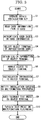
FIG. 4 is a flow chart showing an operation installing a driver of a multifunction peripheral to an external terminal in the multifunction peripheral according a second embodiment of the present disclosure. -
FIG. 5 is a block diagram showing electric structure of an image forming system including a multifunction peripheral according to another embodiment of the present disclosure. -
FIG. 6 is a block diagram showing electric structure of an image forming system according to a further embodiment of the present disclosure. - First, entire structure of a multifunction peripheral 1 (an image forming apparatus) according to a first embodiment of the present disclosure will be described with reference to
FIG. 1 . Hereinafter, for convenience of description, it will be described so that the front side of the multifunction peripheral 1 is positioned at the near side on a paper sheet ofFIG. 1 . Arrows L, R, U and Lo inFIG. 1 respectively indicate a left side, a right side, an upper side and a lower side of the multifunction peripheral 1. - The multifunction peripheral 1 includes a roughly box-formed
apparatus body 2. In a lower part of theapparatus body 2, a plurality ofsheet feeding cartridges 3 storing sheets are provided. In an in-body space of an upper part of theapparatus body 2, an ejectedsheet tray 4 is provided. - In the upper part of the
apparatus body 2, animage reading part 5 reading a document as image data is provided. In a top face of theimage reading part 5, a document table composed of a platen glass is provided. Theimage reading part 5 reads an image of the document placed on the document table by a scanner to create image data. Above theimage reading part 5, adocument conveying part 6 feeding the document to theimage reading part 5 is provided. Thedocument conveying part 6 is openably/closably attached as a cover member covering the platen glass of theimage reading part 5. - Further, in the upper part of the
apparatus body 2, anoperation display part 7 is attached at a front side. Theoperation display part 7 includes, for example, operation keys, such as a ten key, a start key, a system menu key, a transmission key, a copy key and a confirmation ley, and a display device, such as a touch panel, to receive operation input from a user. Theoperation display part 7 includes a driver installation key provided as the operation key or operably displayed on the touch panel. Moreover, in the upper part of theapparatus body 2, acard reader 8 is provided at the front side. When an IC card, such as an employee identification card, of the user using the multifunction peripheral 1 is held up to thecard reader 8, thecard reader 8 reads card information peculiar to the user, such as an employee ID, stored in the IC card with a non-contact manner. - In a central part of the
apparatus body 2, anintermediate transferring belt 10 is windingly stretched among a plurality of conveying rollers. At a lower side of theintermediate transferring belt 10, fourimage forming parts 11 forming the image are provided for respective toner colors (for example, four colors of yellow, magenta, cyan and black). At a lower side of the fourimage forming parts 11, anexposure part 12 is provided. At a right side of theintermediate transferring belt 10, a secondary transferringpart 13 is provided and, at a left side of theintermediate transferring belt 10, acleaning unit 14 cleaning theintermediate transferring belt 10 is provided. The secondary transferringpart 13 is composed of a part at a right end side of theintermediate transferring belt 10 and a secondary transferring roller. - Each
image forming part 11 includes a rotatably photosensitive drum as an image carrier. At the periphery of the photosensitive drum, a charging part, a developing part, a primary transferring part, a static eliminating part and a cleaning device are disposed in a sequential order of electrophotographic process. At an upper side of developing parts of theimage forming parts 11, toner containers corresponding to respectiveimage forming parts 11 are provided for the respective toner colors (for example, four colors of yellow, magenta, cyan and black). Each toner container contains the toner of each color. - At a right side part in the
apparatus body 2, aconveying path 15 of the sheet is provided. At an upstream end of theconveying path 15, a plurality ofsheet feeding part 16 is provided for the respectivesheet feeding cartridges 3. At a middle stream part of theconveying path 15, the above-described secondary transferringpart 13 is provided. At a downstream part of theconveying path 15, afixing device 17 is provided and, at a downstream end of theconveying path 15, asheet ejecting part 18 is provided. - Next, an image forming operation of the multifunction peripheral 1 will be described. In the multifunction peripheral 1, image data is inputted and a printing start is instructed from the
image reading part 5, an external terminal 23 (refer toFIG. 2 ) connected to a communicating part 22 (refer toFIG. 2 ) or the like. In eachimage forming part 11, the photosensitive drum is electrically charged by the charging part, and then, exposed on the basis of the image data by theexposure part 12, and thereby, an electrostatic latent image is formed on the photosensitive drum. The electrostatic latent image on the photosensitive drum is developed for a toner image of each color by the developing part. The toner image on the photosensitive drum is primarily transferred to a surface of theintermediate transferring belt 10 by the primary transferring part. The fourimage forming parts 7 sequentially carry out the above-described operation, and thereby, a toner image of full color (a color toner image) is formed on theintermediate transferring belt 10. The color toner image is supplied to a secondary transferringpart 13 at a predetermined secondary transfer timing by rotation of theintermediate transferring belt 10. - On the other hand, a sheet stored in the
sheet feeding cartridge 3 is picked up by thesheet feeding part 16, and then, conveyed on theconveying path 15. Subsequently, the sheet on theconveying path 15 is conveyed to the secondary transferringpart 13 at the predetermined secondary transfer timing described above. In the secondary transferringpart 13, the color toner image on theintermediate transferring belt 10 is secondarily transferred to the sheet. The sheet having the secondarily transferred color toner image is conveyed to a downstream side on the conveyingpath 15 and, after the color toner image is fixed to the sheet by the fixingpart 17, the sheet is ejected from thesheet ejecting part 18 to the ejectedsheet tray 4. - Next, electric structure of the above-described multifunction peripheral 1 will be described with reference to
FIG. 2 . The multifunction peripheral 1 includes acontrolling part 20, such as CPU, and a storingpart 21, such as ROM and RAM, inside theapparatus body 2. The controllingpart 20 controls each component connected to thecontrolling part 20 on the basis of control programs and control data stored in the storingpart 21. The storingpart 21 stores a host name and an IP address of the multifunction peripheral 1, and a driver name and a storage place (e.g. a URL of a download source or a folder name of a storage source in the multifunction peripheral 1) of a driver of the multifunction peripheral 1. - The controlling
part 20 is connected to theimage reading part 5, theoperation display part 7, thecard reader 8, theimage forming parts 11, theexposure part 12 and other components of the multifunction peripheral 1. Further, the controllingpart 20 is connected to the communicatingpart 22, and the communicatingpart 22 is connected to a plurality ofexternal terminals 23 and adata base 24 via a determined network N, such as a LAN or an internet. Thereby, the multifunction peripheral 1 together with the plurality ofexternal terminals 23, adata base 24 and the network N compose animage forming system 100. - The multifunction peripheral 1 includes a
user authenticating part 25, aterminal selecting part 26 and aninstallation instructing part 27 controlled by the controllingpart 20 in order to execute installing operation making theexternal terminal 23 communicably connected to the multifunction peripheral 1 install the driver of the multifunction peripheral 1. Incidentally, theuser authenticating part 25, theterminal selecting part 26 and theinstallation instructing part 27 may be constructed by programs stored in the storingpart 21 and executed by the controllingpart 20. Details of theuser authenticating part 25, theterminal selecting part 26 and theinstallation instructing part 27 will be described later. - Each
external terminal 23 is a computer, such as a personal computer or a tablet terminal, communicated to the multifunction peripheral 1, and becomes a usable state when log-in of theexternal terminal 23 is carried out by inputting a predetermined log-in password. Eachexternal terminal 23 is constructed so as to permit the communicably connected multifunction peripheral 1 remote access subject to input of the log-in password during log-in, for example, permits remote installation of software, such as the driver. - The
data base 24 registers the user using the multifunction peripheral 1 and eachexternal terminal 23 in previously association with each other, and may register a plurality of users and the plurality ofexternal terminals 23. For example, thedata base 24 registers authentication information corresponding to card information of an ID card of each user, terminal information, such as a computer name, of eachexternal terminal 23 used by each user, and log-in information, such as the log-in password, in association with each other. Thedata base 24 may register oneexternal terminal 23 or the plurality ofexternal terminals 23 in association with one user (one card information). Incidentally, although, in the first embodiment, an example of the data abase 24 as an external device of the multifunction peripheral 1 communicably connected to the multifunction peripheral 1 is described, the data abase 24 may be provided in the multifunction peripheral 1 or data stored in the data abase 24 may be stored in the storingpart 21 of the multifunction peripheral 1. - Moreover, the
data base 24 may register a group ID identifying a group, such as a department, to which each user belongs in association with the user, and may apply a representative flag to the user as a representative of the group, such as a department head. In other words, in thedata base 24, with regard to the user to which the representative flag of a predetermined group is applied, not only the user's ownexternal terminal 23, but also theexternal terminals 23 of other users belonging to the group are associated. - Next, the installing operation in which the multifunction peripheral 1 makes the
external terminal 23 install the driver will be described together with details of theuser authenticating part 25, theterminal selecting part 26 and theinstallation instructing part 27 with reference to a flow chart ofFIG. 3 . - First, when the user operates the driver installation key of the operation display part 7 (step S1), the installing operation is started. When the installing operation is started, the controlling
part 20 displays an instructing screen instructing reading of the IC card to the user by a pop-up screen or the like in theoperation display part 7. - Then, when the user holds up the IC card to the
card reader 8, thecard reader 8 reads the card information from the IC card and transmits the card information to the controlling part 20 (step S2). - When the
controlling part 20 receives the card information from thecard reader 8, the controllingpart 20 controls theuser authenticating part 25 to make theuser authenticating part 25 execute user authentication based on the card information. Theuser authenticating part 25 collates the card information read from the IC card in thecard reader 8 with the authentication information stored in thedata base 24 to authenticate the user (step S3). - When the user is authenticated by the
user authenticating part 25, the controllingpart 20 controls theterminal selecting part 26 to make theterminal selecting part 26 execute selection of the external terminal 23 (an object terminal) as an object of the installing operation. Theterminal selecting part 26 selects theexternal terminal 23 registered in thedata base 24 in association with the user authenticated in the user authenticating part 25 (an authenticated user) as the object terminal (step S4). - Incidentally, the
terminal selecting part 26 may automatically select theexternal terminal 23 associated with the authenticated user as the object terminal, or may display theexternal terminals 23 registered in thedata base 24 in theoperation display part 7 with a list to make the user select the object terminal in accordance with operation of the user. Moreover, theterminal selecting part 26 may select, as the object terminal, the pluralexternal terminals 23 associated with the authenticated user or the pluralexternal terminals 23 registered by the group ID associated with the authenticated user. - When the object terminal is selected in the
terminal selecting part 26, the controllingpart 20 controls theinstallation instructing part 27 to make theinstallation instructing part 27 execute installation instruction of the driver to the object terminal. First, theinstallation instructing part 27 obtains the terminal information and the log-in information with regard to the object terminal stored in the data base 24 (step S5). - Incidentally, the controlling
part 20 can recognize theexternal terminal 23 connected via the network N and during log-in. Thereupon, theinstallation instructing part 27 recognizes the object terminal among theexternal terminals 23 recognized in the controllingpart 20 on the basis of the obtained terminal information. - The
installation instructing part 27 communicates with the recognized object terminal via the network N and establishes remote access to the object terminal by using the log-in information (step S6). For example, theinstallation instructing part 27 displays a password inputting screen showing the terminal information, such as the computer name, in theoperation display part 7 to direct the user to input the log-in information, such as the log-in password. When the user inputs the log-in information, theinstallation instructing part 27 establishes remote access to the object terminal by using the inputted log-in information. - Subsequently, the
installation instructing part 27 transmits installation instruction performing automatic installation of the driver of the multifunction peripheral 1 with so-called silent installation to the object terminal in which the remote access is established (step S7). For example, the installation instruction of the automatic installation is composed of a batch file, an object code, script data or other program indicating the host name and the IP address of the multifunction peripheral 1 and the driver name and the storage place of the driver and is constructed so as to be automatically executed in the object terminal. Incidentally, theinstallation instructing part 27 may transmit the installation instruction accompanied with the driver itself instead of indication of the storage place of the driver. - When the object terminal receives the installation instruction, the object terminal execute the automatic installation of the driver of the multifunction peripheral 1 on the basis of the host name and the IP address of the multifunction peripheral 1 and the driver name and the storage place of the driver indicated by the installation instruction. As a response to the installation instruction, if installation of the driver is succeeded, the object terminal transmits success notification to the multifunction peripheral 1 (step S8). If installation of the driver is failed, the object terminal transmits failure notification to the multifunction peripheral 1. The success notification and the failure notification may be built as response program into the installation instruction, or may be provided as function of the object terminal.
- When the multifunction peripheral 1 receives the success notification of installation from the object terminal, the multifunction peripheral 1 may display a screen showing installation success by a pop-up screen in the
operation display part 7 to notify installation success to the user. Moreover, the multifunction peripheral 1 may store success and failure of installation notified from the object terminal in thedata base 24 in association with each object terminal, and may store a kind and a version about the driver installed to each object terminal on the basis of these notification. - Further, when the multifunction peripheral 1 receives the success notification of installation, the
installation instructing part 27 transmits automatic transmission instruction of test print instruction to the object terminal in order to make the object terminal automatically instruct test print (step S9). Incidentally, the automatic transmission instruction of the test print instruction may be included in the above-described installation instruction. Subsequently, when the object terminal receives the automatic transmission instruction of the test print instruction, the object terminal automatically transmits the test print instruction to the multifunction peripheral 1. The multifunction peripheral 1 executes the test print in accordance with the test print instruction received from the object terminal (step S10) . - In accordance with the first embodiment, as described above, the multifunction peripheral 1 (the image forming apparatus) including the
image forming part 11 forming the image includes theuser authenticating part 25, theterminal selecting part 26 and theinstallation instructing part 27. Theuser authenticating part 25 authenticates the user on the basis of the authentication information peculiar to the user in the installing operation making theexternal terminal 23 communicably connected to the multifunction peripheral 1 install the driver of the multifunction peripheral 1. Theterminal selecting part 26 selects theexternal terminal 23 registered in association with the user authenticated by theuser authenticating part 25 as the object terminal in the installing operation. Theinstallation instructing part 27 establishes remote access to the object terminal on the basis of the log-in information previously registered with regard to the object terminal selected by theterminal selecting part 26 and transmits the installation instruction making the object terminal execute the automatic installation of the driver to the object terminal. - Thereby, if only the user operates the multifunction peripheral 1, the user can install the driver to various
external terminals 23 using the multifunction peripheral 1, and the user does not need to come and go between the multifunction peripheral 1 and eachexternal terminal 23, and therefore, it is possible to restrain labor of the user. Incidentally, although theexternal terminal 23 registered in association with the user is the object terminal in the installation operation, association with the user is not restricted to oneexternal terminal 23, but may have the pluralexternal terminals 23 or may have theexternal terminals 23 of other users belonging to the group in which the former user is representative. - In addition, since works confirming the host name and the IP address of the multifunction peripheral 1 and setting the host name and the IP address to each
external terminal 23 are not required, and it is unnecessary to come and go between the multifunction peripheral 1 and eachexternal terminal 23 in order to confirm such information, it is possible to restrain labor of the user. Thus, it is possible to facilitate installation work of the driver and confirmation work of the host name and the IP address of the image forming apparatus, and to decrease a burden on the user. - Moreover, in a case where the object terminal receiving the installation instruction transmitted by the
installation instructing part 27 succeeds the automatic installation of the driver, if the multifunction peripheral 1 receives the success notification of the automatic installation from the object terminal, theinstallation instructing part 27 transmits the automatic transmission instruction of the test print instruction to the object terminal. - Thereby, in a case where the user executes the test print of the multifunction peripheral 1 with regard to the object terminal to which the driver is installed by operation of the multifunction peripheral 1, the user does not need to come and go between the multifunction peripheral 1 and each
external terminal 23, and therefore, it is possible to restrain labor of the user and to decrease a burden on the user. - In the first embodiment, although an example that the multifunction peripheral 1 establishes remote access to the
external terminal 23 of the object terminal and transmits the installation instruction making the object terminal execute the automatic installation of the driver to the object terminal in the installing operation was described, the present disclosure is not limited by this example. For example, in a second embodiment, the multifunction peripheral 1 is constructed so as to send an e-mail to theexternal terminal 23 of the object terminal to send the in installation instruction to the object terminal in the installing operation. - Hereinafter, the multifunction peripheral 1 in the second embodiment will be described, but description of configuration of the second embodiment similar to the first embodiment is omitted. In the second embodiment, the
data base 24 registering the users using the multifunction peripheral 1 and theexternal terminals 23 in association with each other stores respective e-mail addresses of theexternal terminals 23 instead of the terminal information and the log-in information of theexternal terminals 23. - The installing operation in which the multifunction peripheral 1 in the second embodiment makes the
external terminal 23 install the driver will be described with reference to a flow chart ofFIG. 4 . In the second embodiment, operation from the installing operation is started (step S11) to the user authentication (steps S12 and S13) and selection of theexternal terminal 23 as the object terminal (step S14) is similar to the first embodiment. - When the object terminal is selected in the
terminal selecting part 26, the controllingpart 20 controls theinstallation instructing part 27 to make theinstallation instructing part 27 execute installation instruction of the driver to the object terminal. First, theinstallation instructing part 27 obtains the e-mail address with regard to the object terminal stored in the data base 24 (step S15). - The
installation instructing part 27 sends an e-mail instructing installation of the driver in accordance with operation of the object terminal by the user as the installation instruction to the object terminal (step S16). For example, the installation instruction is composed of the e-mail in which the host name and the IP address of the multifunction peripheral 1, the driver name and the storage place of the driver and other information, such as an installing manual, are written. In such a case, the user reads such information from the e-mail and operates the object terminal on the basis of such information, and thereby, installs the driver. Incidentally, theinstallation instructing part 27 may transmit the e-mail accompanied with the driver itself instead of indication of the storage place of the driver. - Alternatively, the installation instruction is constructed by the e-mail accompanied with an installer file executed in accordance with the user's operation in the object terminal by a batch file, an object code, script data or other program indicating the host name and the IP address of the multifunction peripheral 1 and the driver name and the storage place of the driver. In such a case, the user operates the object terminal to execute the installer file accompanying the e-mail, and thereby, installs the driver.
- Otherwise, the installation instruction is constructed by the e-mail including a URL of a download source of the above-described installer file. In such a case, the user operates the object terminal to download the installer file on the basis of the URL of the download source and to execute the installer file, and thereby, installs the driver.
- When the object terminal receives the installation instruction, the object terminal installs the driver of the multifunction peripheral 1 in accordance with the user's operation on the basis of the installation instruction. Incidentally, in the second embodiment, similar to the first embodiment, in response to the installation instruction, the success notification (step S17) and the failure notification of installation may be executed.
- Moreover, in a case where the object terminal installs the driver on the basis of the installation instruction of the e-mail, the object terminal transmits test print instruction to the multifunction peripheral 1 in accordance with the user's operation (step S18). The multifunction peripheral 1 executes test print in accordance with the test print instruction received from the object terminal. Further, if the
installation instructing part 27 transmits the e-mail with the installation instruction to the object terminal, receives the test print instruction from the object terminal and succeeds the test print, theinstallation instructing part 27 sends success notification of the test print to the object terminal (step S19). - In accordance with the second embodiment, as described above, the multifunction peripheral 1 (the image forming apparatus) including the
image forming part 11 forming the image includes theuser authenticating part 25, theterminal selecting part 26 and theinstallation instructing part 27. Theuser authenticating part 25 authenticates the user on the basis of the authentication information peculiar to the user in the installing operation making theexternal terminal 23 communicably connected to the multifunction peripheral 1 install the driver of the multifunction peripheral 1. Theterminal selecting part 26 selects theexternal terminal 23 registered in association with the user authenticated by theuser authenticating part 25 as the object terminal in the installing operation. Theinstallation instructing part 27 sends the e-mail instructing installation of the driver on the basis of the e-mail address previously registered with regard to the object terminal selected by theterminal selecting part 26 as the installation instruction to the object terminal. - Thereby, the user does not need to confirm the host name and the IP address of the multifunction peripheral 1 and to set the host name and the IP address to each
external terminal 23, and the user does not need to come and go between the multifunction peripheral 1 and eachexternal terminal 23, and therefore, it is possible to restrain labor of the user. Thus, it is possible to facilitate installation work of the driver and confirmation work of the host name and the IP address of the image forming apparatus, and to decrease a burden on the user. - Moreover, in a case where the object terminal receiving the installation instruction of the e-mail transmitted by the
installation instructing part 27 succeeds installation of the driver, if the multifunction peripheral 1 receives the test print instruction from the object terminal and succeeds the test print, the multifunction peripheral 1 transmits success notification of the test print to the object terminal. - Thereby, in a case where the user installs the driver by operation of the object terminal, the user does not need to come and go between the multifunction peripheral 1 and each
external terminal 23 in order to confirm a result of the test print of the multifunction peripheral 1, and therefore, it is possible to restrain labor of the user and to decrease a burden on the user. - Further, in accordance with the first embodiment and the second embodiment, the multifunction peripheral 1 includes the
card reader 8 reading the card information from the IC card storing the card information corresponding to the authentication information of the user. Theuser authenticating part 25 authenticates the user on the basis of the authentication information previously registered in thedata base 24 and the card information read by thecard reader 8. - Thereby, if only the user holds up the IC card to the multifunction peripheral 1, the user can install the driver to the object terminal being the
external terminal 23 registered in association with the user by a simple manner. - For example, the multifunction peripheral 1 is constructed so that the
card reader 8 reads one card information from one IC card in one installing operation. In such a case, theuser authenticating part 25 authenticates one user on the basis of one card information, and theterminal selecting part 26 selects theexternal terminal 23 registered in association with one user as the object terminal. - Alternatively, the multifunction peripheral 1 may be constructed so that the
card reader 8 reads the plural card informations from the plural IC cards in one installing operation. In such a case, thecard reader 8 identifies and reads respective card informations from the plural IC cards held up once in a laminated state, or reads each card information sequentially from the plural IC cards held up one by one for a predetermined time. - Subsequently, the
user authenticating part 25 authenticates the plural users on the basis of the plural card informations. Theterminal selecting part 26 selects the pluralexternal terminals 23 previously registered in association with the plural users authenticated by theuser authenticating part 25 as the plural object terminals in one installing operation, respectively. - Thereby, if only the respective IC cards of the plural users are held up to the multifunction peripheral 1, the user can install the same driver of the same multifunction peripheral 1 to the respective
external terminal 23 of the plural users in one installing operation by a simple manner. - In the first embodiment and the second embodiment, although an example that the
card reader 8 is applied in the multifunction peripheral 1 in order to authenticate the user, the present disclosure is not limited by this example. For example, in another embodiment, the multifunction peripheral 1 further may include a biologicalinformation reading device 30 in order to authenticate the user as shown inFIG. 5 instead of thecard reader 8 or in addition to thecard reader 8. - The biological
information reading device 30 is constructed so as to read biological information, such as a fingerprint or an iris, of the user. In thedata base 24, the authentication information corresponding to the biological information of the user is previously registered in association with the user. The biologicalinformation reading device 30 is controlled by the controllingpart 20 to send the read biological information to thecontrolling part 20. Theuser authenticating part 25 authenticates the user on the basis of the previously registered authentication information and the biological information read by the biologicalinformation reading device 30. - Thereby, the multifunction peripheral 1 can authenticate the user by biological authentication without making the user hold up the IC card, and can make the object terminal being the
external terminal 23 registered in association with the user install the driver by a further simple manner. - In addition, in another embodiment, the biological
information reading device 30 may be constructed so as to identify and read plural biological informations (e.g. fingerprints of respective fingers) of one user, and the data baser 24 registers the plural biological informations with regard to one user. In such a case, if the biologicalinformation reading device 30 reads at least any one of the plural biological informations registered with regard to a predetermined user, theuser authenticating part 25 authenticates the predetermined user. - Moreover, in a case where the
data base 24 registers the pluralexternal terminals 23 in association with the user to which the plural biological informations are registered, thedata base 24 may register differentexternal terminals 23 in association with the plural biological informations, respectively. In this case, if the user is authenticated in the user authenticating part, theterminal selecting part 26 selects theexternal terminal 23 registered in association with the biological information read by the biologicalinformation reading device 30 out of the plural biological informations registered in association with the user as the object terminal. - Thereby, in a case where the plural
external terminals 23 are registered in association with one user, if only the user changes the biological information used for the biological authentication, it is possible to voluntarily select the external terminal 23 (the voluntary external terminal 23) as the object terminal to install the driver by a simple manner. - Incidentally, in a case where the plural biological informations of one user are registered in the
data base 24, theinstallation instructing part 27 may set different installation instructions (e.g. the installation instruction of the automatic installation in the first embodiment and the installation instruction of the e-mail in the second embodiment) for the respective biological informations. - In the above-described embodiments, although an example that the
image forming system 100 includes one multifunction peripheral 1 was described, the present disclosure is not limited by this example. For example, in a further embodiment, as shown inFIG. 6 , theimage forming system 100 may include a plurality ofmultifunction peripherals 1a-1e. In thisimage forming system 100, thedata base 24 stores "installed" or "not-installed" informations about the respective drivers of the plurality ofmultifunction peripherals 1a-1e and a kind and a version of the installed driver for eachexternal terminals 23. - Thereupon, in the
image forming system 100, in a case where the installing operation is carried out in the predetermined multifunction peripheral 1a out of the plurality ofmultifunction peripherals 1a-1e to transmit the installation instruction of the driver of the predetermined multifunction peripheral 1a to the object terminal being theexternal terminal 23 associated with the user, the predetermined multifunction peripheral 1a decides with reference to thedata base 24 whether or not the respective drivers of the othermultifunction peripherals 1b-1e are installed to the object terminal. Subsequently, the predetermined multifunction peripheral 1a transmits the installation instruction of the not-installed driver out of the drivers of the othermultifunction peripherals 1b-1e to the object terminal. Incidentally, the installation instruction of the driver of each of the othermultifunction peripherals 1b-1e may be the installation instruction of the automatic installation in the first embodiment or the installation instruction of the e-mail in the second embodiment. - Although the above-described embodiments have described about a case applying the configuration of the present disclosure to the multifunction peripheral 1 or the
image forming system 100 including the multifunction peripheral, in a further different embodiment, the configuration of the present disclosure may be applied to another image forming apparatus, such as a printer, a copying machine and a facsimile or another image forming system including such another image forming apparatus. - The above-description of the embodiment of the present disclosure was described about a preferable embodiment of the image forming apparatus and the image forming system according to the disclosure. However, the technical scope of the present disclosure is not limited to the embodiments.
Claims (11)
- An image forming apparatus (1) including an image forming part (11) forming an image comprising:a user authenticating part (25) authenticating a user on the basis of authentication information peculiar to the user in installing operation making an external terminal (23) communicably connected to the image forming apparatus (1) install a driver of the image forming apparatus (1);a terminal selecting part (26) selecting the external terminal (23) registered in association with the user authenticated by the user authenticating part (25) as an object terminal (23) in the installing operation; andan installation instructing part (27) establishing remote access to the object terminal (23) on the basis of log-in information previously registered with regard to the object terminal (23) selected by the terminal selecting part (26) and transmitting installation instruction making the object terminal (23) execute automatic installation of the driver to the object terminal (23).
- The image forming apparatus (1) according to claim 1, wherein
in a case where the object terminal (23) receiving the installation instruction transmitted by the installation instructing part (27) succeeds the automatic installation of the driver, if the image forming apparatus (1) receives success notification of the automatic installation from the object terminal (23), the installation instructing part (27) transmits automatic transmission instruction of test print instruction to the object terminal (23). - An image forming apparatus (1) including an image forming part (11) forming an image comprising:a user authenticating part (25) authenticating a user on the basis of authentication information peculiar to the user in installing operation making an external terminal (23) communicably connected to the image forming apparatus (1) install a driver of the image forming apparatus (1);a terminal selecting part (26) selecting the external terminal (23) registered in association with the user authenticated by the user authenticating part (25) as an object terminal (23) in the installing operation; andan installation instructing part (27) sending an e-mail instructing installation of the driver on the basis of an e-mail address previously registered with regard to the object terminal (23) selected by the terminal selecting part (26) as installation instruction to the object terminal (23).
- The image forming apparatus (1) according to claim 3, wherein
in a case where the object terminal (23) receiving the installation instruction of the e-mail transmitted by the installation instructing part (27) succeeds installation of the driver, if the image forming apparatus (1) receives test print instruction from the object terminal (23) and succeeds test print, the image forming apparatus (1) transmits success notification of the test print to the object terminal (23). - The image forming apparatus (1) according to any one of claims 1-4 further comprising:a card reader (8) reading card information from an IC card storing the card information corresponding to the authentication information in the installing operation,wherein the user authenticating part (25) authenticates the user on the basis of the authentication information previously registered and the card information read by the card reader (8).
- The image forming apparatus (1) according to claim 5, wherein
the card reader (8) respectively reads plural card informations from IC cards of plural users in one installing operation,
the user authenticating part (25) authenticates the plural users on the basis of the plural card informations read by the card reader (8),
the terminal selecting part (26) selects plural external terminals (23) previously registered in association with the plural users authenticated by the user authenticating part (25) as plural object terminals (23) in one installing operation, respectively. - The image forming apparatus (1) according to any one of claims 1-4 further comprising:a biological information reading device (30) reading biological information of the user corresponding to the authentication information in the installing operation,wherein the user authenticating part (25) authenticates the user on the basis of the authentication information previously registered and the biological information read by the biological information reading device (30).
- The image forming apparatus (1) according to claim 7, wherein
the biological information reading device (30) identifies and reads one biological information out of plural biological informations previously registered in association with plural external terminals (23) with regard to the user to which the plural external terminals (23) are associated,
the user authenticating part (25) authenticates the user on the basis of one biological information read by the biological information reading device (30),
the terminal selecting part (26) selects the external terminal (23) previously registered in association with one biological information used for authenticating the user by the user authenticating part (25) as the object terminal (23). - The image forming apparatus (1a) according to any one of claims 1-8, wherein
the other image forming apparatus (1b-1e) communicating to the object terminal (23) selected by the terminal selecting part (26) is searched, if a driver of the other image forming apparatus (1b-1e) is not installed to the object terminal (23), the installation instructing part (27) transmits the other installation instruction making the object terminal (23) install the driver of the other image forming apparatus (1b-1e) to the object terminal (23). - An image forming system (100) comprising:the image forming apparatus (1) according to any one of claims 1-8; andthe external terminal (23).
- An image forming system (100) comprising:the image forming apparatus (1a) according to claim 9;the other image forming apparatus (1b-1e); andthe external terminal (23).
Applications Claiming Priority (1)
| Application Number | Priority Date | Filing Date | Title |
|---|---|---|---|
| JP2018171585A JP7127449B2 (en) | 2018-09-13 | 2018-09-13 | Image forming apparatus and image forming system |
Publications (2)
| Publication Number | Publication Date |
|---|---|
| EP3627811A1 true EP3627811A1 (en) | 2020-03-25 |
| EP3627811B1 EP3627811B1 (en) | 2023-10-25 |
Family
ID=67909345
Family Applications (1)
| Application Number | Title | Priority Date | Filing Date |
|---|---|---|---|
| EP19196426.1A Active EP3627811B1 (en) | 2018-09-13 | 2019-09-10 | Image forming apparatus and image forming system |
Country Status (4)
| Country | Link |
|---|---|
| US (1) | US10908856B2 (en) |
| EP (1) | EP3627811B1 (en) |
| JP (1) | JP7127449B2 (en) |
| CN (1) | CN110896430B (en) |
Families Citing this family (1)
| Publication number | Priority date | Publication date | Assignee | Title |
|---|---|---|---|---|
| CN115952505A (en) * | 2021-10-08 | 2023-04-11 | 珠海奔图电子有限公司 | Control method and control device of image forming device and electronic device |
Citations (5)
| Publication number | Priority date | Publication date | Assignee | Title |
|---|---|---|---|---|
| US20020083431A1 (en) * | 2000-12-21 | 2002-06-27 | Haruo Machida | Network system, information processing unit, information processing method, and control program |
| US20090064198A1 (en) * | 2007-08-30 | 2009-03-05 | Katsumi Kobayashi | Apparatus, system, and computer program product for processing information |
| US20090150880A1 (en) * | 2007-12-05 | 2009-06-11 | Samsung Electronics Co., Ltd | Printer driver installing method, recordable medium recorded with program executing the installing method, image forming apparatus and host apparatus thereof |
| US20100107157A1 (en) * | 2008-10-24 | 2010-04-29 | Samsung Electronics Co., Ltd | Server connected with image forming apparatus and client, image forming system having the same, and driver remote installation method of image forming apparatus |
| US20180150268A1 (en) * | 2016-11-28 | 2018-05-31 | S-Printing Solution Co., Ltd. | Image forming apparatus and method for installing printer driver in host device |
Family Cites Families (9)
| Publication number | Priority date | Publication date | Assignee | Title |
|---|---|---|---|---|
| JP3870065B2 (en) | 2001-10-31 | 2007-01-17 | キヤノン株式会社 | Network system, information processing apparatus, information processing method, and control program |
| JP4522061B2 (en) | 2003-07-31 | 2010-08-11 | キヤノン株式会社 | Information processing apparatus and method, and program |
| JP3840244B2 (en) * | 2003-11-12 | 2006-11-01 | キヤノン株式会社 | Printing apparatus, job processing method, storage medium, program |
| JP2005324450A (en) | 2004-05-14 | 2005-11-24 | Canon Inc | Image forming apparatus, information processing apparatus, job display control method, storage medium storing computer-readable program, and program |
| JP4802613B2 (en) | 2005-08-25 | 2011-10-26 | 富士ゼロックス株式会社 | Installation system and installation program |
| JP2007080156A (en) | 2005-09-16 | 2007-03-29 | Canon Inc | Printing device |
| JP2007249650A (en) | 2006-03-16 | 2007-09-27 | Ricoh Co Ltd | Delivery method of installation information |
| EP1975786A1 (en) * | 2007-03-29 | 2008-10-01 | Ricoh Company, Ltd. | Method for installing a printer driver on an end user's computer |
| JP4962532B2 (en) * | 2009-06-17 | 2012-06-27 | コニカミノルタビジネステクノロジーズ株式会社 | Image forming apparatus and computer program |
-
2018
- 2018-09-13 JP JP2018171585A patent/JP7127449B2/en not_active Expired - Fee Related
-
2019
- 2019-09-10 EP EP19196426.1A patent/EP3627811B1/en active Active
- 2019-09-11 US US16/567,650 patent/US10908856B2/en not_active Expired - Fee Related
- 2019-09-11 CN CN201910857976.3A patent/CN110896430B/en not_active Expired - Fee Related
Patent Citations (5)
| Publication number | Priority date | Publication date | Assignee | Title |
|---|---|---|---|---|
| US20020083431A1 (en) * | 2000-12-21 | 2002-06-27 | Haruo Machida | Network system, information processing unit, information processing method, and control program |
| US20090064198A1 (en) * | 2007-08-30 | 2009-03-05 | Katsumi Kobayashi | Apparatus, system, and computer program product for processing information |
| US20090150880A1 (en) * | 2007-12-05 | 2009-06-11 | Samsung Electronics Co., Ltd | Printer driver installing method, recordable medium recorded with program executing the installing method, image forming apparatus and host apparatus thereof |
| US20100107157A1 (en) * | 2008-10-24 | 2010-04-29 | Samsung Electronics Co., Ltd | Server connected with image forming apparatus and client, image forming system having the same, and driver remote installation method of image forming apparatus |
| US20180150268A1 (en) * | 2016-11-28 | 2018-05-31 | S-Printing Solution Co., Ltd. | Image forming apparatus and method for installing printer driver in host device |
Also Published As
| Publication number | Publication date |
|---|---|
| US20200089447A1 (en) | 2020-03-19 |
| CN110896430B (en) | 2022-07-19 |
| US10908856B2 (en) | 2021-02-02 |
| JP2020043538A (en) | 2020-03-19 |
| JP7127449B2 (en) | 2022-08-30 |
| CN110896430A (en) | 2020-03-20 |
| EP3627811B1 (en) | 2023-10-25 |
Similar Documents
| Publication | Publication Date | Title |
|---|---|---|
| US20200288024A1 (en) | Image Reading Device and Image Reading Method | |
| JP7447659B2 (en) | Image forming device, billing method and program | |
| CN100474277C (en) | Image forming apparatus | |
| US9019515B2 (en) | Display input device having a program function, image forming apparatus having a program function, and display method for display input device having a program function | |
| US9785386B2 (en) | Image processing apparatus, case processing apparatus, and image processing method for processing an application based on an agent requested in advance from an applicant to proceed with the application procedure | |
| US8861026B2 (en) | Image forming apparatus | |
| EP3627811B1 (en) | Image forming apparatus and image forming system | |
| JP2006159565A (en) | Printing system | |
| JP6081506B2 (en) | Authentication device | |
| US11070696B2 (en) | Information processing system | |
| US11892954B2 (en) | Self-adding smartcard reader system | |
| US10992828B2 (en) | Image forming apparatus and method for controlling setup information based on a reference apparatus | |
| JP2006235186A (en) | Electrophotographic equipment | |
| US12112080B2 (en) | User authentication for image forming devices | |
| US11714585B2 (en) | Image forming apparatus configured to perform authentication to enable an operation for an authorized user | |
| US10824378B2 (en) | Image forming apparatus, image forming system and non-transitory computer readable medium storing control program | |
| JP2011123249A (en) | Image forming apparatus | |
| JP6710176B2 (en) | Image forming apparatus and user authentication method | |
| JP2007281596A (en) | Information processing apparatus, information processing system, and control method thereof, program, and storage medium | |
| JP5601110B2 (en) | Image forming apparatus, authentication apparatus, image forming system, and program | |
| JP4083750B2 (en) | Image forming apparatus and multifunction machine | |
| JP2021137980A (en) | Printer | |
| JP2012100107A (en) | Log information management device for image forming device, image forming device, control method of log information management device for image forming device, and control program of log information management device for image forming device | |
| JP2019101913A (en) | Image forming apparatus, and image forming system | |
| JP2020184706A (en) | Image forming apparatus and control method of image forming apparatus |
Legal Events
| Date | Code | Title | Description |
|---|---|---|---|
| PUAI | Public reference made under article 153(3) epc to a published international application that has entered the european phase |
Free format text: ORIGINAL CODE: 0009012 |
|
| STAA | Information on the status of an ep patent application or granted ep patent |
Free format text: STATUS: THE APPLICATION HAS BEEN PUBLISHED |
|
| AK | Designated contracting states |
Kind code of ref document: A1 Designated state(s): AL AT BE BG CH CY CZ DE DK EE ES FI FR GB GR HR HU IE IS IT LI LT LU LV MC MK MT NL NO PL PT RO RS SE SI SK SM TR |
|
| AX | Request for extension of the european patent |
Extension state: BA ME |
|
| STAA | Information on the status of an ep patent application or granted ep patent |
Free format text: STATUS: REQUEST FOR EXAMINATION WAS MADE |
|
| 17P | Request for examination filed |
Effective date: 20200918 |
|
| RBV | Designated contracting states (corrected) |
Designated state(s): AL AT BE BG CH CY CZ DE DK EE ES FI FR GB GR HR HU IE IS IT LI LT LU LV MC MK MT NL NO PL PT RO RS SE SI SK SM TR |
|
| STAA | Information on the status of an ep patent application or granted ep patent |
Free format text: STATUS: EXAMINATION IS IN PROGRESS |
|
| 17Q | First examination report despatched |
Effective date: 20211118 |
|
| GRAP | Despatch of communication of intention to grant a patent |
Free format text: ORIGINAL CODE: EPIDOSNIGR1 |
|
| STAA | Information on the status of an ep patent application or granted ep patent |
Free format text: STATUS: GRANT OF PATENT IS INTENDED |
|
| INTG | Intention to grant announced |
Effective date: 20230418 |
|
| P01 | Opt-out of the competence of the unified patent court (upc) registered |
Effective date: 20230420 |
|
| GRAS | Grant fee paid |
Free format text: ORIGINAL CODE: EPIDOSNIGR3 |
|
| GRAA | (expected) grant |
Free format text: ORIGINAL CODE: 0009210 |
|
| STAA | Information on the status of an ep patent application or granted ep patent |
Free format text: STATUS: THE PATENT HAS BEEN GRANTED |
|
| AK | Designated contracting states |
Kind code of ref document: B1 Designated state(s): AL AT BE BG CH CY CZ DE DK EE ES FI FR GB GR HR HU IE IS IT LI LT LU LV MC MK MT NL NO PL PT RO RS SE SI SK SM TR |
|
| REG | Reference to a national code |
Ref country code: GB Ref legal event code: FG4D |
|
| REG | Reference to a national code |
Ref country code: CH Ref legal event code: EP |
|
| REG | Reference to a national code |
Ref country code: DE Ref legal event code: R096 Ref document number: 602019039938 Country of ref document: DE |
|
| REG | Reference to a national code |
Ref country code: IE Ref legal event code: FG4D |
|
| REG | Reference to a national code |
Ref country code: LT Ref legal event code: MG9D |
|
| REG | Reference to a national code |
Ref country code: NL Ref legal event code: MP Effective date: 20231025 |
|
| REG | Reference to a national code |
Ref country code: AT Ref legal event code: MK05 Ref document number: 1625874 Country of ref document: AT Kind code of ref document: T Effective date: 20231025 |
|
| PG25 | Lapsed in a contracting state [announced via postgrant information from national office to epo] |
Ref country code: NL Free format text: LAPSE BECAUSE OF FAILURE TO SUBMIT A TRANSLATION OF THE DESCRIPTION OR TO PAY THE FEE WITHIN THE PRESCRIBED TIME-LIMIT Effective date: 20231025 |
|
| PG25 | Lapsed in a contracting state [announced via postgrant information from national office to epo] |
Ref country code: GR Free format text: LAPSE BECAUSE OF FAILURE TO SUBMIT A TRANSLATION OF THE DESCRIPTION OR TO PAY THE FEE WITHIN THE PRESCRIBED TIME-LIMIT Effective date: 20240126 |
|
| PG25 | Lapsed in a contracting state [announced via postgrant information from national office to epo] |
Ref country code: IS Free format text: LAPSE BECAUSE OF FAILURE TO SUBMIT A TRANSLATION OF THE DESCRIPTION OR TO PAY THE FEE WITHIN THE PRESCRIBED TIME-LIMIT Effective date: 20240225 |
|
| PG25 | Lapsed in a contracting state [announced via postgrant information from national office to epo] |
Ref country code: LT Free format text: LAPSE BECAUSE OF FAILURE TO SUBMIT A TRANSLATION OF THE DESCRIPTION OR TO PAY THE FEE WITHIN THE PRESCRIBED TIME-LIMIT Effective date: 20231025 |
|
| PG25 | Lapsed in a contracting state [announced via postgrant information from national office to epo] |
Ref country code: AT Free format text: LAPSE BECAUSE OF FAILURE TO SUBMIT A TRANSLATION OF THE DESCRIPTION OR TO PAY THE FEE WITHIN THE PRESCRIBED TIME-LIMIT Effective date: 20231025 |
|
| PG25 | Lapsed in a contracting state [announced via postgrant information from national office to epo] |
Ref country code: ES Free format text: LAPSE BECAUSE OF FAILURE TO SUBMIT A TRANSLATION OF THE DESCRIPTION OR TO PAY THE FEE WITHIN THE PRESCRIBED TIME-LIMIT Effective date: 20231025 |
|
| PG25 | Lapsed in a contracting state [announced via postgrant information from national office to epo] |
Ref country code: LT Free format text: LAPSE BECAUSE OF FAILURE TO SUBMIT A TRANSLATION OF THE DESCRIPTION OR TO PAY THE FEE WITHIN THE PRESCRIBED TIME-LIMIT Effective date: 20231025 Ref country code: IS Free format text: LAPSE BECAUSE OF FAILURE TO SUBMIT A TRANSLATION OF THE DESCRIPTION OR TO PAY THE FEE WITHIN THE PRESCRIBED TIME-LIMIT Effective date: 20240225 Ref country code: GR Free format text: LAPSE BECAUSE OF FAILURE TO SUBMIT A TRANSLATION OF THE DESCRIPTION OR TO PAY THE FEE WITHIN THE PRESCRIBED TIME-LIMIT Effective date: 20240126 Ref country code: ES Free format text: LAPSE BECAUSE OF FAILURE TO SUBMIT A TRANSLATION OF THE DESCRIPTION OR TO PAY THE FEE WITHIN THE PRESCRIBED TIME-LIMIT Effective date: 20231025 Ref country code: BG Free format text: LAPSE BECAUSE OF FAILURE TO SUBMIT A TRANSLATION OF THE DESCRIPTION OR TO PAY THE FEE WITHIN THE PRESCRIBED TIME-LIMIT Effective date: 20240125 Ref country code: AT Free format text: LAPSE BECAUSE OF FAILURE TO SUBMIT A TRANSLATION OF THE DESCRIPTION OR TO PAY THE FEE WITHIN THE PRESCRIBED TIME-LIMIT Effective date: 20231025 Ref country code: PT Free format text: LAPSE BECAUSE OF FAILURE TO SUBMIT A TRANSLATION OF THE DESCRIPTION OR TO PAY THE FEE WITHIN THE PRESCRIBED TIME-LIMIT Effective date: 20240226 |
|
| PG25 | Lapsed in a contracting state [announced via postgrant information from national office to epo] |
Ref country code: SE Free format text: LAPSE BECAUSE OF FAILURE TO SUBMIT A TRANSLATION OF THE DESCRIPTION OR TO PAY THE FEE WITHIN THE PRESCRIBED TIME-LIMIT Effective date: 20231025 Ref country code: RS Free format text: LAPSE BECAUSE OF FAILURE TO SUBMIT A TRANSLATION OF THE DESCRIPTION OR TO PAY THE FEE WITHIN THE PRESCRIBED TIME-LIMIT Effective date: 20231025 Ref country code: PL Free format text: LAPSE BECAUSE OF FAILURE TO SUBMIT A TRANSLATION OF THE DESCRIPTION OR TO PAY THE FEE WITHIN THE PRESCRIBED TIME-LIMIT Effective date: 20231025 Ref country code: NO Free format text: LAPSE BECAUSE OF FAILURE TO SUBMIT A TRANSLATION OF THE DESCRIPTION OR TO PAY THE FEE WITHIN THE PRESCRIBED TIME-LIMIT Effective date: 20240125 Ref country code: LV Free format text: LAPSE BECAUSE OF FAILURE TO SUBMIT A TRANSLATION OF THE DESCRIPTION OR TO PAY THE FEE WITHIN THE PRESCRIBED TIME-LIMIT Effective date: 20231025 Ref country code: HR Free format text: LAPSE BECAUSE OF FAILURE TO SUBMIT A TRANSLATION OF THE DESCRIPTION OR TO PAY THE FEE WITHIN THE PRESCRIBED TIME-LIMIT Effective date: 20231025 |
|
| PG25 | Lapsed in a contracting state [announced via postgrant information from national office to epo] |
Ref country code: DK Free format text: LAPSE BECAUSE OF FAILURE TO SUBMIT A TRANSLATION OF THE DESCRIPTION OR TO PAY THE FEE WITHIN THE PRESCRIBED TIME-LIMIT Effective date: 20231025 |
|
| PG25 | Lapsed in a contracting state [announced via postgrant information from national office to epo] |
Ref country code: CZ Free format text: LAPSE BECAUSE OF FAILURE TO SUBMIT A TRANSLATION OF THE DESCRIPTION OR TO PAY THE FEE WITHIN THE PRESCRIBED TIME-LIMIT Effective date: 20231025 |
|
| REG | Reference to a national code |
Ref country code: DE Ref legal event code: R097 Ref document number: 602019039938 Country of ref document: DE |
|
| PG25 | Lapsed in a contracting state [announced via postgrant information from national office to epo] |
Ref country code: SK Free format text: LAPSE BECAUSE OF FAILURE TO SUBMIT A TRANSLATION OF THE DESCRIPTION OR TO PAY THE FEE WITHIN THE PRESCRIBED TIME-LIMIT Effective date: 20231025 |
|
| PG25 | Lapsed in a contracting state [announced via postgrant information from national office to epo] |
Ref country code: SM Free format text: LAPSE BECAUSE OF FAILURE TO SUBMIT A TRANSLATION OF THE DESCRIPTION OR TO PAY THE FEE WITHIN THE PRESCRIBED TIME-LIMIT Effective date: 20231025 Ref country code: SK Free format text: LAPSE BECAUSE OF FAILURE TO SUBMIT A TRANSLATION OF THE DESCRIPTION OR TO PAY THE FEE WITHIN THE PRESCRIBED TIME-LIMIT Effective date: 20231025 Ref country code: RO Free format text: LAPSE BECAUSE OF FAILURE TO SUBMIT A TRANSLATION OF THE DESCRIPTION OR TO PAY THE FEE WITHIN THE PRESCRIBED TIME-LIMIT Effective date: 20231025 Ref country code: IT Free format text: LAPSE BECAUSE OF FAILURE TO SUBMIT A TRANSLATION OF THE DESCRIPTION OR TO PAY THE FEE WITHIN THE PRESCRIBED TIME-LIMIT Effective date: 20231025 Ref country code: EE Free format text: LAPSE BECAUSE OF FAILURE TO SUBMIT A TRANSLATION OF THE DESCRIPTION OR TO PAY THE FEE WITHIN THE PRESCRIBED TIME-LIMIT Effective date: 20231025 Ref country code: DK Free format text: LAPSE BECAUSE OF FAILURE TO SUBMIT A TRANSLATION OF THE DESCRIPTION OR TO PAY THE FEE WITHIN THE PRESCRIBED TIME-LIMIT Effective date: 20231025 Ref country code: CZ Free format text: LAPSE BECAUSE OF FAILURE TO SUBMIT A TRANSLATION OF THE DESCRIPTION OR TO PAY THE FEE WITHIN THE PRESCRIBED TIME-LIMIT Effective date: 20231025 |
|
| PLBE | No opposition filed within time limit |
Free format text: ORIGINAL CODE: 0009261 |
|
| STAA | Information on the status of an ep patent application or granted ep patent |
Free format text: STATUS: NO OPPOSITION FILED WITHIN TIME LIMIT |
|
| 26N | No opposition filed |
Effective date: 20240726 |
|
| PG25 | Lapsed in a contracting state [announced via postgrant information from national office to epo] |
Ref country code: SI Free format text: LAPSE BECAUSE OF FAILURE TO SUBMIT A TRANSLATION OF THE DESCRIPTION OR TO PAY THE FEE WITHIN THE PRESCRIBED TIME-LIMIT Effective date: 20231025 |
|
| PG25 | Lapsed in a contracting state [announced via postgrant information from national office to epo] |
Ref country code: SI Free format text: LAPSE BECAUSE OF FAILURE TO SUBMIT A TRANSLATION OF THE DESCRIPTION OR TO PAY THE FEE WITHIN THE PRESCRIBED TIME-LIMIT Effective date: 20231025 |
|
| REG | Reference to a national code |
Ref country code: DE Ref legal event code: R119 Ref document number: 602019039938 Country of ref document: DE |
|
| PG25 | Lapsed in a contracting state [announced via postgrant information from national office to epo] |
Ref country code: MC Free format text: LAPSE BECAUSE OF FAILURE TO SUBMIT A TRANSLATION OF THE DESCRIPTION OR TO PAY THE FEE WITHIN THE PRESCRIBED TIME-LIMIT Effective date: 20231025 |
|
| REG | Reference to a national code |
Ref country code: CH Ref legal event code: PL |
|
| PG25 | Lapsed in a contracting state [announced via postgrant information from national office to epo] |
Ref country code: LU Free format text: LAPSE BECAUSE OF NON-PAYMENT OF DUE FEES Effective date: 20240910 |
|
| GBPC | Gb: european patent ceased through non-payment of renewal fee |
Effective date: 20240910 |
|
| PG25 | Lapsed in a contracting state [announced via postgrant information from national office to epo] |
Ref country code: DE Free format text: LAPSE BECAUSE OF NON-PAYMENT OF DUE FEES Effective date: 20250401 |
|
| PG25 | Lapsed in a contracting state [announced via postgrant information from national office to epo] |
Ref country code: GB Free format text: LAPSE BECAUSE OF NON-PAYMENT OF DUE FEES Effective date: 20240910 |
|
| REG | Reference to a national code |
Ref country code: BE Ref legal event code: MM Effective date: 20240930 |
|
| PG25 | Lapsed in a contracting state [announced via postgrant information from national office to epo] |
Ref country code: BE Free format text: LAPSE BECAUSE OF NON-PAYMENT OF DUE FEES Effective date: 20240930 |
|
| PG25 | Lapsed in a contracting state [announced via postgrant information from national office to epo] |
Ref country code: FR Free format text: LAPSE BECAUSE OF NON-PAYMENT OF DUE FEES Effective date: 20240930 |
|
| PG25 | Lapsed in a contracting state [announced via postgrant information from national office to epo] |
Ref country code: CH Free format text: LAPSE BECAUSE OF NON-PAYMENT OF DUE FEES Effective date: 20240930 |
|
| PG25 | Lapsed in a contracting state [announced via postgrant information from national office to epo] |
Ref country code: IE Free format text: LAPSE BECAUSE OF NON-PAYMENT OF DUE FEES Effective date: 20240910 |
|
| PG25 | Lapsed in a contracting state [announced via postgrant information from national office to epo] |
Ref country code: FI Free format text: LAPSE BECAUSE OF FAILURE TO SUBMIT A TRANSLATION OF THE DESCRIPTION OR TO PAY THE FEE WITHIN THE PRESCRIBED TIME-LIMIT Effective date: 20231025 |
|
| PG25 | Lapsed in a contracting state [announced via postgrant information from national office to epo] |
Ref country code: CY Free format text: LAPSE BECAUSE OF FAILURE TO SUBMIT A TRANSLATION OF THE DESCRIPTION OR TO PAY THE FEE WITHIN THE PRESCRIBED TIME-LIMIT; INVALID AB INITIO Effective date: 20190910 |
|
| PG25 | Lapsed in a contracting state [announced via postgrant information from national office to epo] |
Ref country code: HU Free format text: LAPSE BECAUSE OF FAILURE TO SUBMIT A TRANSLATION OF THE DESCRIPTION OR TO PAY THE FEE WITHIN THE PRESCRIBED TIME-LIMIT; INVALID AB INITIO Effective date: 20190910 |
|
| PG25 | Lapsed in a contracting state [announced via postgrant information from national office to epo] |
Ref country code: TR Free format text: LAPSE BECAUSE OF FAILURE TO SUBMIT A TRANSLATION OF THE DESCRIPTION OR TO PAY THE FEE WITHIN THE PRESCRIBED TIME-LIMIT Effective date: 20231025 |