EP3627787A1 - Ofdm based radar detection - Google Patents
Ofdm based radar detection Download PDFInfo
- Publication number
- EP3627787A1 EP3627787A1 EP18196127.7A EP18196127A EP3627787A1 EP 3627787 A1 EP3627787 A1 EP 3627787A1 EP 18196127 A EP18196127 A EP 18196127A EP 3627787 A1 EP3627787 A1 EP 3627787A1
- Authority
- EP
- European Patent Office
- Prior art keywords
- sequence
- subcarriers
- radar signal
- radar
- range
- Prior art date
- Legal status (The legal status is an assumption and is not a legal conclusion. Google has not performed a legal analysis and makes no representation as to the accuracy of the status listed.)
- Granted
Links
Images


Classifications
-
- H—ELECTRICITY
- H04—ELECTRIC COMMUNICATION TECHNIQUE
- H04L—TRANSMISSION OF DIGITAL INFORMATION, e.g. TELEGRAPHIC COMMUNICATION
- H04L27/00—Modulated-carrier systems
- H04L27/32—Carrier systems characterised by combinations of two or more of the types covered by groups H04L27/02, H04L27/10, H04L27/18 or H04L27/26
- H04L27/34—Amplitude- and phase-modulated carrier systems, e.g. quadrature-amplitude modulated carrier systems
- H04L27/36—Modulator circuits; Transmitter circuits
- H04L27/362—Modulation using more than one carrier, e.g. with quadrature carriers, separately amplitude modulated
- H04L27/364—Arrangements for overcoming imperfections in the modulator, e.g. quadrature error or unbalanced I and Q levels
-
- G—PHYSICS
- G01—MEASURING; TESTING
- G01S—RADIO DIRECTION-FINDING; RADIO NAVIGATION; DETERMINING DISTANCE OR VELOCITY BY USE OF RADIO WAVES; LOCATING OR PRESENCE-DETECTING BY USE OF THE REFLECTION OR RERADIATION OF RADIO WAVES; ANALOGOUS ARRANGEMENTS USING OTHER WAVES
- G01S7/00—Details of systems according to groups G01S13/00, G01S15/00, G01S17/00
- G01S7/02—Details of systems according to groups G01S13/00, G01S15/00, G01S17/00 of systems according to group G01S13/00
- G01S7/03—Details of HF subsystems specially adapted therefor, e.g. common to transmitter and receiver
-
- H—ELECTRICITY
- H04—ELECTRIC COMMUNICATION TECHNIQUE
- H04L—TRANSMISSION OF DIGITAL INFORMATION, e.g. TELEGRAPHIC COMMUNICATION
- H04L27/00—Modulated-carrier systems
- H04L27/26—Systems using multi-frequency codes
- H04L27/2601—Multicarrier modulation systems
- H04L27/2602—Signal structure
- H04L27/261—Details of reference signals
- H04L27/2613—Structure of the reference signals
-
- H—ELECTRICITY
- H04—ELECTRIC COMMUNICATION TECHNIQUE
- H04L—TRANSMISSION OF DIGITAL INFORMATION, e.g. TELEGRAPHIC COMMUNICATION
- H04L27/00—Modulated-carrier systems
- H04L27/26—Systems using multi-frequency codes
- H04L27/2601—Multicarrier modulation systems
- H04L27/2614—Peak power aspects
-
- H—ELECTRICITY
- H04—ELECTRIC COMMUNICATION TECHNIQUE
- H04L—TRANSMISSION OF DIGITAL INFORMATION, e.g. TELEGRAPHIC COMMUNICATION
- H04L5/00—Arrangements affording multiple use of the transmission path
- H04L5/0001—Arrangements for dividing the transmission path
- H04L5/0003—Two-dimensional division
- H04L5/0005—Time-frequency
- H04L5/0007—Time-frequency the frequencies being orthogonal, e.g. OFDM(A) or DMT
- H04L5/001—Time-frequency the frequencies being orthogonal, e.g. OFDM(A) or DMT the frequencies being arranged in component carriers
Definitions
- Example embodiments relate to orthogonal frequency-division multiplexing, OFDM, based radar signals, methods for generating such radar signals and to a radar for transmission and reception of such radar signals.
- Orthogonal frequency-division multiplexing is a technique wherein information is multiplexed onto a multitude of subcarriers or tones. OFDM has proven to be very effective for wideband wireless and wired data communication and is widely used for digital television and audio broadcasting, subscriber-line based internet access, wireless area networks, power line networks, and 4G mobile communications.
- OFDM has also been proposed for radar detection as it can provide highly desired features such as spectrum-shaping, the use of multiple access schemes (OFDMA) and dynamic spectrum management.
- OFDM radar transmit chain a predefined frequency domain, FD, sequence is mapped onto the set of subcarriers resulting in a FD radar signal.
- the FD signal is then converted to the time domain, TD, upconverted onto a carrier frequency within the radar spectrum band and repeatedly transmitted as TD radar signals.
- TD radar receive chain the received TD radar signals are downconverted to baseband (DC) and converted back to the frequency domain.
- DC baseband
- a Doppler profile may be derived conveying information on the speed of the detected objects.
- the output resulting from the combination of the range and Doppler profiles is typically referred to as a range-Doppler map.
- OFDM based radar detection may suffer from front-end non-idealities such as IQ imbalance originating from the analogue quadrature receiver, i.e. different distortion between the in-phase and quadrature portions of the received radar signal.
- IQ imbalance will manifest in both the range and Doppler profiles. Due to the different nature of these profiles, solutions for overcoming IQ imbalance in wireless communication systems cannot be applied one-to-one onto OFDM radar detection systems.
- an orthogonal frequency-division multiplexing, OFDM, based radar signal comprising Q sub-carriers adapted to push an IQ-imbalance component out of a subset of L contiguous range bins of range profiles derived out of the received radar signal; and wherein L is at most Q/2.
- the radar signal may be represented in the frequency domain by a sequence of Q in-phase (I) and quadrature (Q) values, by an in-phase and quadrature time domain baseband symbol, either digital or analogue, or by a time domain symbol upconverted to a carrier frequency within a radar band of interest.
- I in-phase
- Q quadrature
- neither the Doppler profile or the range profiles will be affected by the IQ-imbalance of a direct conversion receiver or the IQ-imbalance will at least be greatly reduced.
- a radar signal according to the first aspect is characterized by the absence of a reduced IQ-imbalance component in the derived range-Doppler map when taking L ⁇ Q/2.
- Radar signals according to the first aspect may be constructed in various ways as will be illustrated by the example embodiments.
- a radar system can be obtained that is robust to IQ-imbalance by merely adapting the signal itself.
- This further has the advantage that less stringent IQ-imbalance requirements can be imposed on the direct conversion receiver of a radar. All in all, this leads to a much simpler, more efficient and less expensive radar system.
- the range profile may for example correspond to a matched filter range profile, a zero-forcing range profile, or a mean minimum square error range profile may be used. Also, other linear or non-linear range profile estimators may be used.
- the OFDM based radar signal is robust to IQ-imbalance when a Hadamard product of:
- the radar signal when the sequence of subcarriers is selected according to the above properties, then the radar signal will be robust to IQ-imbalance when selecting the L ⁇ Q/2 range bins out of the received signal.
- the properties only relate to the sequence itself, the radar signal will be independent on other characteristics of the radar system or on variable characteristics such as the wireless channel. Hence, it is always possible to form a predefined sequence of radar signals that are robust IQ-imbalance.
- L equals Q/2 and the Hadamard product corresponds to a sequence of a same complex scalar constant with alternating sign.
- the maximum of range bins Q/2 may be obtained when selecting the FD sequence according to these conditions. This thus results in the most optimal use of the frequency spectrum and, hence, an optimal range and velocity range.
- the intermediate FD sequence further fulfils the condition that d) the positive subcarriers have equal magnitudes.
- the IQ imbalance will further be cancelled out for both a zero forcing range profile and matched filter range profile.
- OFDM based radar signal has a Peak-to-Average Power Ratio, PAPR of at most two.
- the radar signals according to the first aspect there always exists a radar signal with a Peak-to-Average Power Ratio, PAPR of at most two. It is an advantage that by achieving a low PAPR the power amplifier's back-off requirements can be relaxed and the power amplifier may work closer to its saturation point thereby increasing the detection range and improving the amplifier's power efficiency
- the positive or negative subcarriers of the intermediate FD sequence may then further correspond to a Golay sequence.
- the intermediate FD sequence may be further characterized by a Golay sequence.
- a second aspect of the present invention relates to a method for generating the radar signal according to the first aspect.
- the method comprises the step of providing a sequence of Q frequency domain, FD, OFDM subcarriers such that a Hadamard product of i) an inverse or complex conjugate transpose of a sequence of the Q sub-carriers represented in the frequency domain, the FD sequence, and ii) a complex conjugate of the FD sequence wherein the order of subcarriers of the FD sequence is reversed, is orthogonal to the 2L-1 subcarriers centred around the direct current, DC, subcarrier of a Fourier transformation matrix indicative for the relation between the time domain, TD, and FD representation of the OFDM radar signal; and the step of transforming the sequence from the frequency domain to the time domain based on the Fourier transformation matrix thereby obtaining the radar signal.
- the FD sequence further corresponds to a complex scalar constant multiplied by an intermediate FD sequence fulfilling the following conditions:
- the method further comprises providing Golay sequences as candidates for the positive or negative subcarriers of the intermediate FD sequence; deriving therefrom candidate FD sequences by applying the conditions b) and c); and selecting from the candidates a selected FD sequence with an optimal PAPR.
- the invention relates to a radar configured to generate the TD radar signal according to the first aspect and/or to perform the method according to the second aspect.
- the radar is further configured to receive the radar signal; to transform the received radar signal to the FD thereby obtaining the Q subcarriers; and to derive from the Q subcarriers a range bin with L elements.
- the radar is a multiple-input and multiple-output, MIMO, radar.
- vectors and matrices are denoted by a single and double under-bar respectively ( a and A ); the superscript * is used to indicate the complex conjugate ( a *); the superscripts T and H denote the matrix transpose and complex conjugate transpose respectively ( A T and A H ).
- D (.) is a diagonal operator such that D ( a ) is a diagonal matrix whose diagonal is equal to a and d (.) is a diagonal operator such that d ( A ) is a vector containing the diagonal of matrix A ; frequency domain, FD, variables are represented with a tilde ( ⁇ ); a full size Fourier transformation matrix is denoted as F and a partial Fourier transformation matrix with K rows and L columns is denoted as F KL ; the Hadamard or element-wise product of two vectors is denoted as a ⁇ b ; I L is an identity matrix of size L .
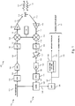
- Fig. 1 shows a block diagram of an OFDM based radar 100 for the detection of the speed and range of remote objects by transmitting OFDM based radar signals 113 and receiving the reflected radar signals 114.
- radar 100 comprises a transmit chain 150 for generating and transmitting the radar signals 113 and a receive chain 160 for receiving the reflected radar signals 114 deriving therefrom range and Doppler profiles 139, 140.
- Radar 100 will further be described with reference to Fig. 2 showing different representations 101, 107, 127, 137 of the radar signals within the different stages of the transmit and receive chains 150, 160.
- Radar 100 initiates a radar transmission from a sequence 101 of in-phase and quadrature, I and Q, values of the Q subcarriers of the OFDM radar signal.
- sequence 101 is represented by a vector s ⁇ with sub-carrier indices q ⁇ ⁇ 0,Q-1 ⁇ wherein index 0 ( Fig. 2 , 210) corresponds to the DC subcarrier, indices ⁇ ⁇ 1,Q/2 ⁇ ( Fig. 2 , 211) correspond to the positive side, i.e., the subcarriers above carrier frequency, and elements ⁇ ⁇ Q/2 + 1,Q - 1 ⁇ ( Fig. 2 , 212) correspond to the negative side (the subcarriers below the carrier frequency).
- Radar 100 is further configured to perform an inverse Fourier transform, IFFT, on the sequence 101 by a circuitry 102 and to obtain a digital time domain symbol representation 103 of the radar signal of duration T (220, 221).
- IFFT inverse Fourier transform
- Radar 100 further comprises a digital-to-analogue converter, DAC, 104 for converting the digital radar signal 103 into an analogue time domain symbol representation 105 with duration T.
- Radar 100 may further comprise a low-pass filter, LPF, circuit 106 for filtering out higher frequency components from the radar signal 105 to obtain the filtered radar signal 107.
- Radar 100 further comprises a mixer 108 for converting the radar signal 107 up to a carrier frequency F 0 thereby obtaining a radar signal 109 within an appropriate radar frequency band.
- Radar 100 further comprises a power amplifier, PA, 110 for amplifying the radar signal 109 to an amplified radar signal 111 which, on its turn, is transmitted as a wireless radar signal 113 by an antenna 112.
- PA power amplifier
- Radar 100 is further configured to repeatedly transmit the radar signals 113.
- the sequence is a repetition 220, 221 of the same time domain symbol 107, there is no need to insert a cyclic prefix in between each repetition for avoiding intersymbolic interference, ISI.
- the radar 100 is configured to receive this reflected radar signal 114 by the antenna 112. Similar to the transmit chain 150, the receive chain 160 comprises a low-noise amplifier 116, a direct conversion mixer 118 and a low pass filter 120 for respectively amplifying the radar signal 115 to an amplified received radar signal 117, down mixing this amplified radar signal 117 to a baseband radar signal 119, and low pass filtering of the baseband radar signal 119 to a filtered baseband radar signal 121. Radar 100 further comprises an amplifier 122 with an adjustable gain for matching of the filtered signal 121 to the input of the analogue to digital converter, ADC, 124.
- ADC analogue to digital converter
- This converter 124 converts the received analogue radar signal 123 to a digital discrete version 125 of the radar signal.
- the receive chain 160 further comprises circuitry 126 for performing a Fourier transform of the radar signal 125 to the frequency domain, i.e., to derive in-phase and quadrature, I and Q, values of the Q subcarriers 230, 231, 232 of the OFDM radar signal.
- the received Q subcarriers 127 are further processed in block 128 by an element-wise operation with the known transmitted sequence 101. This may for example be done by a zero-forcing, ZF, matched filter, MF, a simple ZF or a minimum mean square error, MMSE, estimator.
- the result of the correlation is then converted back to the time domain by performing an inverse Fourier transformation in block 136 thereby obtaining a range profile p L 137, i.e. a range profile using L range bins 241 from the total of Q subcarriers.
- the above range profile estimators are all linear estimators. Other estimators may be applied to the receive chain 160 as long as only L (240) range bins 241 are reconstructed out of the full-length range profile 137 and L is at most Q/2. All multiplications with partial Fourier matrices F KL or F ⁇ KL H in the above linear range profile estimators may be implemented with classical full FFTs by either forcing inputs to zero or discarding outputs, as relevant.
- the range profiles 137 are further repeatedly derived for each received repeated symbol 220, 221 thereby obtaining a set of range profiles. From this set, radar 100 derives a set of Doppler profiles 139 by performing a further Fourier transform 138 on the L range bins 240 of the set of range profiles.
- Radar 100 is further configured to select the input sequence 101 such that an introduced IQ-imbalance originating from the direct conversion mixer 118 between the in-phase and quadrature values of the Q subcarriers affects the radar detection minimally, i.e., the IQ-imbalance does not show up in the derived Doppler profiles 139 or the derived range profiles 140. Analytically, this may be done by selecting the FD sequence s ⁇ 101 such that the IQ imbalance component in the range profiles is cancelled or minimized.
- X ⁇ IQ ⁇ F ⁇ ⁇ H D ⁇ ⁇ s ⁇ ⁇ ⁇ 1 P ⁇ ⁇ D ⁇ ⁇ s ⁇ ⁇ * h ⁇ ⁇ *
- X ⁇ IQ ⁇ F ⁇ ⁇ H D ⁇ ⁇ s ⁇ ⁇ H P ⁇ ⁇ D ⁇ ⁇ s ⁇ ⁇ * h ⁇ ⁇ *
- Eq. 5a or 5b cannot be fulfilled when considering the complete range profiles, i.e., when trying to cancel the IQ imbalance in all range bins of the range profiles.
- X IQ can be cancelled when only considering L ⁇ Q/2 contiguous subcarriers 240 out of the Q subcarriers.
- a sequence s ⁇ exists such that Eq. 5a or Eq. 5b is orthogonal to the 2L-1 subcarriers centred around the direct current, DC, subcarrier of the Fourier transformation matrix F H .
- the IQ imbalance will be pushed out of the set of L range bins of the considered range profile.
- s ⁇ may be constructed as follows:
- the positive subcarriers further have equal magnitudes because in this case the constructed sequence s ⁇ will also comply with equation 5b resulting in a sequence that cancels the IQ-balance for both zero-forcing and matched filter derived range profiles.
- the obtained sequence s ⁇ is further compatible with sub-carrier loading, i.e. with the assigning of different powers to the different sub-carriers. This may be desirable for spectrum shaping, for cognitive radar applications or other radar design requirements.
- the additional degree of freedom may further be exploited to minimize the peak-to-average-power-ratio, PAPR.
- PAPR peak-to-average-power-ratio
- the radar system 100 may be operated by the repeated transmission of the same OFDM radar signal 113.
- the PAPR may therefore be determined by a single OFDM radar symbol.
- the PAPR of an OFDM symbol may be as high as 10 log 10 ( Q ).
- Golay complementary FD symbols may be used to guarantee an upper bound of 2 (3dB), regardless of the OFDM symbol size Q.
- An additional advantage of such Golay sequences is that their elements have a unit magnitude such the MF range profile is identical to the ZF range profile thereby achieving zero range sidelobes.
- a problem with Golay sequences is that they do not fulfil the condition of (Eq. 5) for an OFDM radar signal that is robust to IQ imbalance.
- the FD sequence 101 may be designed as follows. First a length Q / 2 Golay sequence is constructed and mapped to the positive side 211 of the sub-carriers 101. The negative side 212 is then derived from the positive side by applying the constraint of (Eq. 5) or the above procedure 1) to 6) resulting in a length Q FD sequence 101.
- Fig. 3 to Fig. 6 illustrate respective range-Doppler maps 300, 400, 500, 600 obtained by a simulation of the radar system 100 with the parameters as provided in Table 1 below wherein the first column describes the used applicable parameter, the second column shows the symbol for the respective parameter and the third column its respective value:
- Table 1 parameters of simulated radar system Carrier frequency F 0 79GHz Bandwidth B 0.5GHz Number of sub-carriers (Range FFT size) Q 512 Number of OFDM symbols (Doppler FFT size) N 512 Range window Hamming Reduced number of range bins L 256 Doppler window Blackman Range resolution R res 30cm Ambiguous range R amb 153.9m Velocity resolution v res 0.9km/h Ambiguous velocity v amb 238.4km/h Target position 10m Target velocity 15m/s IQ Phase mismatch (For Fig. 4 , 5 and 6 ) ⁇ ⁇ ⁇ 10° IQ Amplitude mismatch (For Fig. 4 , 5 and 6
- QPSK quadrature phase shift keying
- the detected range and velocity of the object is clearly visible as peak 501.
- the map 600 shows a strong interference "ridge" 602 visible at a velocity opposite to the target velocity of the object. This interference 602 appears as a ridge 602 over all range bins because, using a random sequence for the radar signal spreads the energy over all the range bins. The interference 602 may thus jeopardize the correct detection of the object's peak 601 or trigger a false detection.
- Range-Doppler maps 700 and 800 illustrates the case of map 600 but wherein the random QPSK based sequence is replace with a waveform optimized for both IQ-imbalance suppression and low PAPR as described according to the above embodiments.
- the above radar system 100 has been described as a single input single output, SISO, system.
- the principle of IQ-imbalance compensation and PAPR reduction according to the above embodiment, may also be equally applied to radars that use multiple input or output antennas, i.e. SIMO, MISO and MIMO radars.
- circuitry may refer to one or more or all of the following:
- circuitry also covers an implementation of merely a hardware circuit or processor (or multiple processors) or portion of a hardware circuit or processor and its (or their) accompanying software and/or firmware.
- circuitry also covers, for example and if applicable to the particular claim element, a baseband integrated circuit or processor integrated circuit for a mobile device or a similar integrated circuit in a server, a cellular network device, or other computing or network device.
- top, bottom, over, under, and the like are introduced for descriptive purposes and not necessarily to denote relative positions. It is to be understood that the terms so used are interchangeable under appropriate circumstances and embodiments of the invention are capable of operating according to the present invention in other sequences, or in orientations different from the one(s) described or illustrated above.
Landscapes
- Engineering & Computer Science (AREA)
- Computer Networks & Wireless Communication (AREA)
- Signal Processing (AREA)
- Physics & Mathematics (AREA)
- General Physics & Mathematics (AREA)
- Radar, Positioning & Navigation (AREA)
- Remote Sensing (AREA)
- Radar Systems Or Details Thereof (AREA)
Abstract
Description
- Example embodiments relate to orthogonal frequency-division multiplexing, OFDM, based radar signals, methods for generating such radar signals and to a radar for transmission and reception of such radar signals.
- Orthogonal frequency-division multiplexing (OFDM) is a technique wherein information is multiplexed onto a multitude of subcarriers or tones. OFDM has proven to be very effective for wideband wireless and wired data communication and is widely used for digital television and audio broadcasting, subscriber-line based internet access, wireless area networks, power line networks, and 4G mobile communications.
- In recent years, OFDM has also been proposed for radar detection as it can provide highly desired features such as spectrum-shaping, the use of multiple access schemes (OFDMA) and dynamic spectrum management. In an OFDM radar transmit chain a predefined frequency domain, FD, sequence is mapped onto the set of subcarriers resulting in a FD radar signal. The FD signal is then converted to the time domain, TD, upconverted onto a carrier frequency within the radar spectrum band and repeatedly transmitted as TD radar signals. In an OFDM radar receive chain the received TD radar signals are downconverted to baseband (DC) and converted back to the frequency domain. By using the known transmitted sequence, a range profile is constructed conveying range information of one or more objects within the detection range of the radar. Furthermore, from the range bins of such set of range profiles, a Doppler profile may be derived conveying information on the speed of the detected objects. The output resulting from the combination of the range and Doppler profiles is typically referred to as a range-Doppler map.
- However, just as OFDM based data communication, also OFDM based radar detection may suffer from front-end non-idealities such as IQ imbalance originating from the analogue quadrature receiver, i.e. different distortion between the in-phase and quadrature portions of the received radar signal. Moreover, the IQ imbalance will manifest in both the range and Doppler profiles. Due to the different nature of these profiles, solutions for overcoming IQ imbalance in wireless communication systems cannot be applied one-to-one onto OFDM radar detection systems.
- Amongst others, it is an object of the present invention to overcome the above identified problem and to foresee in a solution for OFDM based radar detection that is robust to IQ imbalance.
- This object is achieved, according to a first aspect of the present disclosure, by an orthogonal frequency-division multiplexing, OFDM, based radar signal comprising Q sub-carriers adapted to push an IQ-imbalance component out of a subset of L contiguous range bins of range profiles derived out of the received radar signal; and wherein L is at most Q/2.
- The radar signal may be represented in the frequency domain by a sequence of Q in-phase (I) and quadrature (Q) values, by an in-phase and quadrature time domain baseband symbol, either digital or analogue, or by a time domain symbol upconverted to a carrier frequency within a radar band of interest. As shown by example embodiments, it is possible to construct a radar signal that will push out IQ-imbalance out of L contiguous range bins of the range profiles. In other words, when limiting the range bins to L≤Q/2 upon constructing the range-Doppler map, neither the Doppler profile or the range profiles will be affected by the IQ-imbalance of a direct conversion receiver or the IQ-imbalance will at least be greatly reduced. Hence, a radar signal according to the first aspect is characterized by the absence of a reduced IQ-imbalance component in the derived range-Doppler map when taking L≤Q/2. Radar signals according to the first aspect may be constructed in various ways as will be illustrated by the example embodiments.
- It is thus an advantage that by the radar signal according to the first aspect, a radar system can be obtained that is robust to IQ-imbalance by merely adapting the signal itself. This further has the advantage that less stringent IQ-imbalance requirements can be imposed on the direct conversion receiver of a radar. All in all, this leads to a much simpler, more efficient and less expensive radar system.
- For constructing the range profile may for example correspond to a matched filter range profile, a zero-forcing range profile, or a mean minimum square error range profile may be used. Also, other linear or non-linear range profile estimators may be used.
- According to an example embodiment, the OFDM based radar signal is robust to IQ-imbalance when a Hadamard product of:
- i) an inverse or complex conjugate transpose of a sequence of the Q sub-carriers represented in the frequency domain, the FD sequence, and
- ii) a complex conjugate of the FD sequence wherein the order of subcarriers of the FD sequence is reversed,
- In other words, when the sequence of subcarriers is selected according to the above properties, then the radar signal will be robust to IQ-imbalance when selecting the L≤Q/2 range bins out of the received signal. As the properties only relate to the sequence itself, the radar signal will be independent on other characteristics of the radar system or on variable characteristics such as the wireless channel. Hence, it is always possible to form a predefined sequence of radar signals that are robust IQ-imbalance.
- According to an example embodiment, L equals Q/2 and the Hadamard product corresponds to a sequence of a same complex scalar constant with alternating sign.
- According to an example embodiment, the FD sequence for L=Q/2 will correspond to this Hadamard product when the FD sequence corresponds to a complex scalar constant multiplied by an intermediate FD sequence fulfilling the following conditions:
- a) the direct current, DC, subcarrier and the highest frequency subcarrier of the FD sequence are real;
- b) mirror subcarriers have equal magnitudes; and
- c) the sum of the phases of mirror subcarriers is 180 degrees for odd subcarriers and 0 degrees for even subcarriers.
- In other words, the maximum of range bins Q/2 may be obtained when selecting the FD sequence according to these conditions. This thus results in the most optimal use of the frequency spectrum and, hence, an optimal range and velocity range.
- Advantageously, the intermediate FD sequence further fulfils the condition that d) the positive subcarriers have equal magnitudes. In such a case, the IQ imbalance will further be cancelled out for both a zero forcing range profile and matched filter range profile.
- According to a further embodiment, OFDM based radar signal has a Peak-to-Average Power Ratio, PAPR of at most two.
- As shown by example embodiments, within the radar signals according to the first aspect, there always exists a radar signal with a Peak-to-Average Power Ratio, PAPR of at most two. It is an advantage that by achieving a low PAPR the power amplifier's back-off requirements can be relaxed and the power amplifier may work closer to its saturation point thereby increasing the detection range and improving the amplifier's power efficiency
- The positive or negative subcarriers of the intermediate FD sequence may then further correspond to a Golay sequence. In other words, to select a sequence with a PAPR of at most two, the intermediate FD sequence may be further characterized by a Golay sequence.
- A second aspect of the present invention relates to a method for generating the radar signal according to the first aspect. The method comprises the step of providing a sequence of Q frequency domain, FD, OFDM subcarriers such that a Hadamard product of i) an inverse or complex conjugate transpose of a sequence of the Q sub-carriers represented in the frequency domain, the FD sequence, and ii) a complex conjugate of the FD sequence wherein the order of subcarriers of the FD sequence is reversed, is orthogonal to the 2L-1 subcarriers centred around the direct current, DC, subcarrier of a Fourier transformation matrix indicative for the relation between the time domain, TD, and FD representation of the OFDM radar signal; and the step of transforming the sequence from the frequency domain to the time domain based on the Fourier transformation matrix thereby obtaining the radar signal.
- According to example embodiments of the method L=Q/2 and the FD sequence further corresponds to a complex scalar constant multiplied by an intermediate FD sequence fulfilling the following conditions:
- a) the direct current, DC, subcarrier and the highest frequency subcarrier of the FD sequence are real;
- b) mirror subcarriers have equal magnitudes; and
- c) the sum of the phases of mirror subcarriers is 180 degrees for odd subcarriers and 0 degrees for even subcarriers.
- According to further example embodiments of the method, the method further comprises providing Golay sequences as candidates for the positive or negative subcarriers of the intermediate FD sequence; deriving therefrom candidate FD sequences by applying the conditions b) and c); and selecting from the candidates a selected FD sequence with an optimal PAPR.
- According to a third aspect, the invention relates to a radar configured to generate the TD radar signal according to the first aspect and/or to perform the method according to the second aspect.
- According to example embodiments, the radar is further configured to receive the radar signal; to transform the received radar signal to the FD thereby obtaining the Q subcarriers; and to derive from the Q subcarriers a range bin with L elements.
- According to example embodiments, the radar is a multiple-input and multiple-output, MIMO, radar.
- Some example embodiments will now be described with reference to the accompanying drawings.
-
Fig. 1 shows a radar according to an example embodiment; -
Fig. 2 shows a radar signal used by the radar according to an example embodiment; -
Fig. 3 shows a histogram of peak-to-average-ratios of radar signals according to an example embodiment; -
Fig. 4 shows a histogram of peak-to-average-ratios of radar signals according to another example embodiment; -
Fig. 5 illustrates a range-Doppler map of a received random radar signal by a radar without IQ-imbalance; -
Fig. 6 illustrates a range-Doppler map of a received random radar signal by a radar with IQ-imbalance; -
Fig. 7 illustrates a range-Doppler map of a received radar signal adapted to cancel out an IQ-imbalance component in L=Q/2 range bins; and -
Fig. 8 illustrates the range-Doppler map ofFig. 7 limited to the L=Q/2 range bins. - The following notational conventions are used in the below description: vectors and matrices are denoted by a single and double under-bar respectively ( a and A ); the superscript * is used to indicate the complex conjugate (a*); the superscripts T and H denote the matrix transpose and complex conjugate transpose respectively ( A T and A H ). D (.) is a diagonal operator such that D ( a ) is a diagonal matrix whose diagonal is equal to a and d (.) is a diagonal operator such that d ( A ) is a vector containing the diagonal of matrix A ; frequency domain, FD, variables are represented with a tilde (ã); a full size Fourier transformation matrix is denoted as F and a partial Fourier transformation matrix with K rows and L columns is denoted as F KL ; the Hadamard or element-wise product of two vectors is denoted as a ⊙ b ; I L is an identity matrix of size L.
-
Fig. 1 shows a block diagram of an OFDM basedradar 100 for the detection of the speed and range of remote objects by transmitting OFDM based radar signals 113 and receiving the reflected radar signals 114. To this respect,radar 100 comprises a transmitchain 150 for generating and transmitting the radar signals 113 and a receivechain 160 for receiving the reflected radar signals 114 deriving therefrom range andDoppler profiles Radar 100 will further be described with reference toFig. 2 showingdifferent representations chains Radar 100 initiates a radar transmission from asequence 101 of in-phase and quadrature, I and Q, values of the Q subcarriers of the OFDM radar signal. In this disclosure,sequence 101 is represented by a vector s̃ with sub-carrier indices q ∈ {0,Q-1} wherein index 0 (Fig. 2 , 210) corresponds to the DC subcarrier, indices ∈ {1,Q/2} (Fig. 2 , 211) correspond to the positive side, i.e., the subcarriers above carrier frequency, and elements ∈ {Q/2 + 1,Q - 1} (Fig. 2 , 212) correspond to the negative side (the subcarriers below the carrier frequency).Radar 100 is further configured to perform an inverse Fourier transform, IFFT, on thesequence 101 by acircuitry 102 and to obtain a digital timedomain symbol representation 103 of the radar signal of duration T (220, 221).Radar 100 further comprises a digital-to-analogue converter, DAC, 104 for converting thedigital radar signal 103 into an analogue timedomain symbol representation 105 withduration T. Radar 100 may further comprise a low-pass filter, LPF,circuit 106 for filtering out higher frequency components from theradar signal 105 to obtain the filteredradar signal 107.Radar 100 further comprises amixer 108 for converting theradar signal 107 up to a carrier frequency F0 thereby obtaining aradar signal 109 within an appropriate radar frequency band.Radar 100 further comprises a power amplifier, PA, 110 for amplifying theradar signal 109 to an amplifiedradar signal 111 which, on its turn, is transmitted as awireless radar signal 113 by anantenna 112.Radar 100 is further configured to repeatedly transmit the radar signals 113. As the sequence is arepetition time domain symbol 107, there is no need to insert a cyclic prefix in between each repetition for avoiding intersymbolic interference, ISI. - A portion of the transmitted
radar signal 113 will reflect onto an encountered object as a reflectedradar signal 114. Theradar 100 is configured to receive this reflectedradar signal 114 by theantenna 112. Similar to the transmitchain 150, the receivechain 160 comprises a low-noise amplifier 116, adirect conversion mixer 118 and alow pass filter 120 for respectively amplifying theradar signal 115 to an amplified receivedradar signal 117, down mixing this amplifiedradar signal 117 to abaseband radar signal 119, and low pass filtering of thebaseband radar signal 119 to a filteredbaseband radar signal 121.Radar 100 further comprises anamplifier 122 with an adjustable gain for matching of the filteredsignal 121 to the input of the analogue to digital converter, ADC, 124. Thisconverter 124 converts the receivedanalogue radar signal 123 to a digitaldiscrete version 125 of the radar signal. The receivechain 160 further comprisescircuitry 126 for performing a Fourier transform of theradar signal 125 to the frequency domain, i.e., to derive in-phase and quadrature, I and Q, values of theQ subcarriers Q subcarriers 127 are further processed inblock 128 by an element-wise operation with the known transmittedsequence 101. This may for example be done by a zero-forcing, ZF, matched filter, MF, a simple ZF or a minimum mean square error, MMSE, estimator. The result of the correlation is then converted back to the time domain by performing an inverse Fourier transformation inblock 136 thereby obtaining arange profile p L 137, i.e. a range profile usingL range bins 241 from the total of Q subcarriers. Analytically, therange profile p L 136 of a receivedradar signal r 125 may be obtained by configuring the receivechain 160 as follows:


-

range profile 137 using a matched filter; -

range profile 137 using zero forcing; -

range profile 137 using simplified zero forcing; -

range profile 137 using minimum mean square error; - a subset of K sub-carriers is used out of the Q subcarriers;
- only L number (240) of range bins (241) are reconstructed out of the full-length range profile;
- the L reconstructed range bins (240) are contiguous;
- the covered range (240) of L range bins may start at any position;
- L is at most Q/2;
- r is the received time
domain radar signal 125; and - σ n is an estimate of the receiver's noise variance.
- The above range profile estimators are all linear estimators. Other estimators may be applied to the receive
chain 160 as long as only L (240) rangebins 241 are reconstructed out of the full-length range profile 137 and L is at most Q/2. All multiplications with partial Fourier matrices F KL or
- The range profiles 137 are further repeatedly derived for each received repeated
symbol radar 100 derives a set of Doppler profiles 139 by performing afurther Fourier transform 138 on theL range bins 240 of the set of range profiles. -
Radar 100 is further configured to select theinput sequence 101 such that an introduced IQ-imbalance originating from thedirect conversion mixer 118 between the in-phase and quadrature values of the Q subcarriers affects the radar detection minimally, i.e., the IQ-imbalance does not show up in the derived Doppler profiles 139 or the derived range profiles 140. Analytically, this may be done by selecting theFD sequence s̃ 101 such that the IQ imbalance component in the range profiles is cancelled or minimized. - For the zero forcing range profile


- X IQ is the IQ-imbalance component in the zero forcing range profile

- β is the imbalance in the quadrature branch of the receive signal;
- h̃ is the channel response;
- P is a permutation matrix reversing the order of the subcarriers, i.e., for a column


- Similarly, for the matched filter range profile


- The criteria under Eq. 5a or 5b cannot be fulfilled when considering the complete range profiles, i.e., when trying to cancel the IQ imbalance in all range bins of the range profiles. However, X IQ can be cancelled when only considering L≤Q/2
contiguous subcarriers 240 out of the Q subcarriers. In such a case a sequence s̃ exists such that Eq. 5a or Eq. 5b is orthogonal to the 2L-1 subcarriers centred around the direct current, DC, subcarrier of the Fourier transformation matrix F H. In this case, the IQ imbalance will be pushed out of the set of L range bins of the considered range profile. Furthermore, for the simple zero forcing range profile

- Preferably, L=Q/2 because this results in the largest range coverage. In this case, Eq. 5a may be simplified by finding the sequence s̃ such that:

- 1) the
first element 210 of s̃ is real, i.e. the direct current, DC, subcarrier (210) of theFD sequence 101 is real; - 2) The amplitude and phases of the elements on the
positive side 211 of the spectrum can take any value, e.g. they may have a unit or random magnitude, their phase may be zero or any random value; - 3) The magnitudes of the elements on the
negative side 212 satisfy the condition that |s̃(q)| = |s̃(Q- q)| or, in other words, mirror subcarriers have equal magnitudes; - 4) The phases of the elements on the
negative side 212 satisfy the condition that ∠s̃(q) + ∠s̃(Q - q) = qπ or, in other words, the sum of the phases ofmirror subcarriers - 5) The (Q/2 + 1)-th element of s must be real or, in other words, the highest frequency subcarrier (213) of the FD sequence is real;
- 6) The resulting solution from 1) to 5) may further be scaled by any complex scalar constant.
- Preferably, the positive subcarriers further have equal magnitudes because in this case the constructed sequence s̃ will also comply with equation 5b resulting in a sequence that cancels the IQ-balance for both zero-forcing and matched filter derived range profiles.
- When using a
sequence s̃ 101 obtained from the above conditions 1) to 6), therange profile 137 may be obtained by any of the above range profile equations (Eq.4) wherein K=Qand L=Q/2. For each of these range profiles the IQ-imbalance component will at least partially be pushed out of the L considered range bins. As there are a plurality of solutions for s̃ , other optimization criteria may be imposed as described below. The obtained sequence s̃ is further compatible with sub-carrier loading, i.e. with the assigning of different powers to the different sub-carriers. This may be desirable for spectrum shaping, for cognitive radar applications or other radar design requirements. - According to an embodiment, the additional degree of freedom may further be exploited to minimize the peak-to-average-power-ratio, PAPR. Achieving a low PAPR is crucial in wireless and radar transmissions since it relaxes the power amplifier's 110 back-off requirements and allows working closer to saturation thereby increasing the detection range and improving the PA's 110 power efficiency. The PAPR expressed in dB of the discrete-time
TD radar signal 103 represented by t is:
- The
radar system 100 may be operated by the repeated transmission of the sameOFDM radar signal 113. The PAPR may therefore be determined by a single OFDM radar symbol. The PAPR of an OFDM symbol may be as high as 10log 10(Q). To reduce PAPR, Golay complementary FD symbols may be used to guarantee an upper bound of 2 (3dB), regardless of the OFDM symbol size Q. An additional advantage of such Golay sequences is that their elements have a unit magnitude such the MF range profile is identical to the ZF range profile thereby achieving zero range sidelobes. A problem with Golay sequences is that they do not fulfil the condition of (Eq. 5) for an OFDM radar signal that is robust to IQ imbalance. - In order to overcome this problem and, thus, to jointly suppress the interference due to IQ imbalance and achieve a low PAPR, the
FD sequence 101 may be designed as follows. First a length Q/2 Golay sequence is constructed and mapped to thepositive side 211 of the sub-carriers 101. Thenegative side 212 is then derived from the positive side by applying the constraint of (Eq. 5) or the above procedure 1) to 6) resulting in a lengthQ FD sequence 101. The Golay sequence may for example be constructed by the following recursive procedure to:
- the sequence has a length M = 2 m ;
- Ak (n) and Bk (n) are zero for n < 0 and for n > 2 m ;
- weights Wk have a range from {-1,1}; and
- delays Dk are selected as a permutation of {1,2,4, ..., 2 m }.
- At least one of the 2 mm!
possible sequences 101 will have a PAPR of 2 or less. More specifically, when using real Golay sequences, asequence 101 may be obtained with a PAPR of exactly 2. When using complex Golay sequences obtained by a counter clockwise π/2 rotation of real Golay sequences, asequence 101 can be obtained with a PAPR lower than 2. In other words, by performing an exhaustive search over the possible Golay based sequences, asequence 101 can be selected which is robust to IQ-imbalance and has a PAPR of 2 or less. For example, when Q=256, there are 645120 Golay sequences and for Q=512, there are 10321920 Golay sequences. -
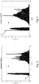
Fig. 3 shows ahistogram 300 of the obtained PAPR on the X-axis forsequences 101 with length Q=512 when using complex Golay sequences. From the histogram, it can be observed 301 that a sequence with a PAPR smaller than 2 can be obtained.Fig. 4 shows ahistogram 400 of the obtained PAPR on the X-axis forsequences 101 with length Q=512 when using complex Golay sequences. From the histogram, it can be observed 401 that a sequence with a PAPR equal to 2 can be obtained. -
Fig. 3 to Fig. 6 illustrate respective range-Doppler maps radar system 100 with the parameters as provided in Table 1 below wherein the first column describes the used applicable parameter, the second column shows the symbol for the respective parameter and the third column its respective value:Table 1: parameters of simulated radar system Carrier frequency F 0 79GHz Bandwidth B 0.5GHz Number of sub-carriers (Range FFT size) Q 512 Number of OFDM symbols (Doppler FFT size) N 512 Range window Hamming Reduced number of range bins L 256 Doppler window Blackman Range resolution Rres 30cm Ambiguous range Ramb 153.9m Velocity resolution vres 0.9km/h Ambiguous velocity vamb 238.4km/h Target position 10m Target velocity 15m/s IQ Phase mismatch (For Fig. 4 ,5 and 6 )Δφ ±10° IQ Amplitude mismatch (For Fig. 4 ,5 and 6 )ε ±10% - These parameters correspond to a typical automotive Medium Range Radar (MRR) scenario in the 79GHz band. The ambiguous and resolution range and velocity were computed using the following equations:




- Range-
Doppler map 500 illustrates an ideal case without IQ-imbalance, i.e. Δφ = 0 and ε = 0, wherein the radar signal is based on a random complex waveform, drawn from a quadrature phase shift keying, QPSK, alphabet. There is asmall ridge 502 along the range dimension between -50 and -60dB which is a degradation of the range sidelobes due to the velocity of the object. There are also somesidelobes 503 along the Doppler dimension due to the combined effect of the Doppler shift and the applied windowing. The detected range and velocity of the object is clearly visible aspeak 501. - Range-
Doppler map 600 illustrates the same case ofmap 500 but with an added IQ-imbalance of Δφ = ±10° and ε = ±10%. Themap 600 shows a strong interference "ridge" 602 visible at a velocity opposite to the target velocity of the object. Thisinterference 602 appears as aridge 602 over all range bins because, using a random sequence for the radar signal spreads the energy over all the range bins. Theinterference 602 may thus jeopardize the correct detection of the object'speak 601 or trigger a false detection. - Range-
Doppler maps map 600 but wherein the random QPSK based sequence is replace with a waveform optimized for both IQ-imbalance suppression and low PAPR as described according to the above embodiments. Inmap 700, theinterference 702 due to the IQ imbalance is still visible but has been pushed beyond half of the range bins. As the design constraints imply that L=Q/2=256, only half of the range profile is used. TheIQ distortion 702 is thus pushed from the L first range bins to the last L range bins that are discarded. Range-Doppler map 800 illustrates thesame case 700 but with the last L range bins discarded, i.e. only the first L=256 range bins are shown. The remaininginterference 802 due to the IQ imbalance is almost 70dB below the target power and, hence, negligible. - The
above radar system 100 has been described as a single input single output, SISO, system. The principle of IQ-imbalance compensation and PAPR reduction according to the above embodiment, may also be equally applied to radars that use multiple input or output antennas, i.e. SIMO, MISO and MIMO radars. - As used in this application, the term "circuitry" may refer to one or more or all of the following:
- (a) hardware-only circuit implementations such as implementations in only analog and/or digital circuitry and
- (b) combinations of hardware circuits and software, such as (as applicable):
- (i) a combination of analog and/or digital hardware circuit(s) with software/firmware and
- (ii) any portions of hardware processor(s) with software (including digital signal processor(s)), software, and memory(ies) that work together to cause an apparatus, such as a mobile phone or server, to perform various functions) and
- (c) hardware circuit(s) and/or processor(s), such as microprocessor(s) or a portion of a microprocessor(s), that requires software (e.g. firmware) for operation, but the software may not be present when it is not needed for operation.
- This definition of circuitry applies to all uses of this term in this application, including in any claims. As a further example, as used in this application, the term circuitry also covers an implementation of merely a hardware circuit or processor (or multiple processors) or portion of a hardware circuit or processor and its (or their) accompanying software and/or firmware. The term circuitry also covers, for example and if applicable to the particular claim element, a baseband integrated circuit or processor integrated circuit for a mobile device or a similar integrated circuit in a server, a cellular network device, or other computing or network device.
- Although the present invention has been illustrated by reference to specific embodiments, it will be apparent to those skilled in the art that the invention is not limited to the details of the foregoing illustrative embodiments, and that the present invention may be embodied with various changes and modifications without departing from the scope thereof. The present embodiments are therefore to be considered in all respects as illustrative and not restrictive, the scope of the invention being indicated by the appended claims rather than by the foregoing description, and all changes which come within the scope of the claims are therefore intended to be embraced therein.
- It will furthermore be understood by the reader of this patent application that the words "comprising" or "comprise" do not exclude other elements or steps, that the words "a" or "an" do not exclude a plurality, and that a single element, such as a computer system, a processor, or another integrated unit may fulfil the functions of several means recited in the claims. Any reference signs in the claims shall not be construed as limiting the respective claims concerned. The terms "first", "second", third", "a", "b", "c", and the like, when used in the description or in the claims are introduced to distinguish between similar elements or steps and are not necessarily describing a sequential or chronological order. Similarly, the terms "top", "bottom", "over", "under", and the like are introduced for descriptive purposes and not necessarily to denote relative positions. It is to be understood that the terms so used are interchangeable under appropriate circumstances and embodiments of the invention are capable of operating according to the present invention in other sequences, or in orientations different from the one(s) described or illustrated above.
Claims (15)
- An orthogonal frequency-division multiplexing, OFDM, based radar signal (101, 103, 105, 107, 111, 113, 114, 115, 117, 119, 121, 123, 125, 127) comprising Q sub-carriers (210-212, 230-232) adapted to push an IQ-imbalance component (602, 702) out of a subset (240) of L contiguous range bins (241) of range profiles (137) derived out of the received (127) radar signal; and wherein L is at most Q/2.
- The OFDM based radar signal according to claim 1 wherein the range profiles are derived by any of zero-forcing, matched filter or mean minimum square error processing.
- The OFDM based radar signal according to claim 1 or 2 wherein a Hadamard product of:i) an inverse or complex conjugate transpose of a sequence (101) of the Q sub-carriers represented in the frequency domain, the FD sequence, andii) a complex conjugate of the FD sequence wherein the order of subcarriers of the FD sequence is reversed,is orthogonal to the 2L-1 subcarriers centred around the direct current, DC, subcarrier of a Fourier transformation matrix indicative for the relation between the time domain, TD, and FD representation of the OFDM radar signal.
- The OFDM based radar signal according to claim 3 wherein L=Q/2 (240) and the Hadamard product corresponds to a sequence of a same complex scalar constant with alternating sign.
- The OFDM based radar signal according to claim3 wherein L=Q/2 (240); and wherein the FD sequence (101) corresponds to a complex scalar constant multiplied by an intermediate FD sequence fulfilling the following conditions:a) the direct current, DC, subcarrier (210) and the highest frequency subcarrier (213) of the FD sequence are real;b) mirror subcarriers have equal magnitudes; andc) the sum of the phases of mirror subcarriers (211, 212) is 180 degrees for odd subcarriers and 0 degrees for even subcarriers.
- The OFDM based radar signal according to claim 5 wherein the intermediate FD sequence further fulfils the following condition:d) the positive subcarriers have equal magnitudes.
- The OFDM based radar signal (103, 105) according to any one of the preceding claims wherein a Peak-to-Average Power Ratio, PAPR is at most two.
- The OFDM based radar signal according to claim 5 wherein the positive or negative subcarriers (211, 212) of the intermediate FD sequence correspond to a Golay sequence.
- A method for generating the radar signal according to any one of the claims 1 to 8 comprising:- providing a sequence of Q frequency domain, FD, OFDM subcarriers (101) such that a Hadamard product of i) an inverse or complex conjugate transpose of a sequence (101) of the Q sub-carriers represented in the frequency domain, the FD sequence, and ii) a complex conjugate of the FD sequence wherein the order of subcarriers of the FD sequence is reversed, is orthogonal to the 2L-1 subcarriers centred around the direct current, DC, subcarrier of a Fourier transformation matrix indicative for the relation between the time domain, TD, and FD representation of the OFDM radar signal; and- transforming (102) the sequence from the frequency domain to the time domain based on the Fourier transformation matrix thereby obtaining the radar signal.
- The method according to claim 9 wherein L=Q/2; and wherein the FD sequence (101) corresponds to a complex scalar constant multiplied by an intermediate FD sequence fulfilling the following conditions:a) the direct current, DC, subcarrier (210) and the highest frequency subcarrier (213) of the FD sequence are real;b) mirror subcarriers (211, 212) have equal magnitudes; andc) the sum of the phases of mirror subcarriers is 180 degrees for odd subcarriers and 0 degrees for even subcarriers.
- The method according to claim 7 wherein the method further comprises:- providing Golay sequences as candidates for the positive (211) or negative (212) subcarriers of the intermediate FD sequence;
deriving therefrom candidate FD sequences by applying conditions b) and c); and- selecting from the candidates a selected FD sequence with an optimal PAPR. - A radar (100) configured to generate the TD radar signal (113) according to any one of the claims 1 to 8.
- The radar (100) according to claim 12 further configured to perform the method according to any one of claims 9 to 11.
- The radar (100) according to claim 12 or 13 further configured to:- receive (112) the radar signal (114);- transform (116-126) the received radar signal to the FD thereby obtaining the Q subcarriers;- derive (129, 131, 133) from the Q subcarriers a range profile with L contiguous range bins.
- The radar according to any one of claims 9 to 11 wherein the radar is a multiple-input and multiple-output, MIMO, radar.
Priority Applications (2)
| Application Number | Priority Date | Filing Date | Title |
|---|---|---|---|
| EP18196127.7A EP3627787B1 (en) | 2018-09-22 | 2018-09-22 | Ofdm based radar detection |
| US16/578,156 US11641303B2 (en) | 2018-09-22 | 2019-09-20 | System and method for performing orthogonal frequency-division multiplexing (OFDM) based radar detection |
Applications Claiming Priority (1)
| Application Number | Priority Date | Filing Date | Title |
|---|---|---|---|
| EP18196127.7A EP3627787B1 (en) | 2018-09-22 | 2018-09-22 | Ofdm based radar detection |
Publications (2)
| Publication Number | Publication Date |
|---|---|
| EP3627787A1 true EP3627787A1 (en) | 2020-03-25 |
| EP3627787B1 EP3627787B1 (en) | 2023-01-25 |
Family
ID=63713612
Family Applications (1)
| Application Number | Title | Priority Date | Filing Date |
|---|---|---|---|
| EP18196127.7A Active EP3627787B1 (en) | 2018-09-22 | 2018-09-22 | Ofdm based radar detection |
Country Status (2)
| Country | Link |
|---|---|
| US (1) | US11641303B2 (en) |
| EP (1) | EP3627787B1 (en) |
Cited By (1)
| Publication number | Priority date | Publication date | Assignee | Title |
|---|---|---|---|---|
| EP4001954A1 (en) | 2020-11-17 | 2022-05-25 | Imec VZW | Method for radar detection and digitally modulated radar robust to iq imbalance |
Families Citing this family (6)
| Publication number | Priority date | Publication date | Assignee | Title |
|---|---|---|---|---|
| EP3912340B1 (en) * | 2019-01-14 | 2025-03-26 | Aura Intelligent Systems, Inc. | Sub-band and multi-band coded ofdm for high-resolution radar |
| CN113504514B (en) * | 2021-07-12 | 2022-04-15 | 石家庄铁道大学 | Frequency control array MIMO radar receiving end structure design and signal processing method |
| TR2021019284A2 (en) * | 2021-12-07 | 2021-12-21 | Univ Istanbul Medipol | PEAK-AVERAGE POWER RATIO REDUCTION WITH RADAR AND COMMUNICATION SYSTEMS |
| US20250028035A2 (en) * | 2023-02-10 | 2025-01-23 | University Of Notre Dame Du Lac | Apparatus, system, and method for improving resolution of frequency-dependent objects in radar contexts |
| US12625230B2 (en) * | 2023-09-15 | 2026-05-12 | Nxp B.V. | Signal processing for OFDM radar systems |
| CN118549891B (en) * | 2024-07-26 | 2024-10-25 | 中国人民解放军国防科技大学 | Multi-carrier orthogonal frequency division multiplexing radar interference integrated waveform modulation method and device |
Citations (2)
| Publication number | Priority date | Publication date | Assignee | Title |
|---|---|---|---|---|
| US20080219339A1 (en) * | 2007-03-09 | 2008-09-11 | Qualcomm Incorporated | Channel estimation using frequency smoothing |
| US20170264477A1 (en) * | 2016-03-08 | 2017-09-14 | Blackberry Limited | Method and apparatus for i-q decoupled ofdm modulation and demodulation |
Family Cites Families (5)
| Publication number | Priority date | Publication date | Assignee | Title |
|---|---|---|---|---|
| US8634496B2 (en) | 2007-10-31 | 2014-01-21 | Imec | Method for determining and compensating transceiver non-idealities |
| WO2010056204A2 (en) | 2008-11-12 | 2010-05-20 | Agency For Science, Technology And Research | A multiple access communication system |
| KR101278025B1 (en) * | 2009-10-15 | 2013-06-21 | 한국전자통신연구원 | Receiving apparatus with OFDM I/Q imbalance compensation and method thereof |
| US8441393B2 (en) * | 2010-02-10 | 2013-05-14 | Tialinx, Inc. | Orthogonal frequency division multiplexing (OFDM) radio as radar |
| CN107147596A (en) | 2017-06-06 | 2017-09-08 | 电子科技大学 | A Compensation Method for IQ Imbalance of Single Carrier System Based on Golay Sequence |
-
2018
- 2018-09-22 EP EP18196127.7A patent/EP3627787B1/en active Active
-
2019
- 2019-09-20 US US16/578,156 patent/US11641303B2/en active Active
Patent Citations (2)
| Publication number | Priority date | Publication date | Assignee | Title |
|---|---|---|---|---|
| US20080219339A1 (en) * | 2007-03-09 | 2008-09-11 | Qualcomm Incorporated | Channel estimation using frequency smoothing |
| US20170264477A1 (en) * | 2016-03-08 | 2017-09-14 | Blackberry Limited | Method and apparatus for i-q decoupled ofdm modulation and demodulation |
Non-Patent Citations (2)
| Title |
|---|
| BOURDOUX ANDRE ET AL: "IQ Imbalance Robust OFDM Radar Waveform", 2018 15TH EUROPEAN RADAR CONFERENCE (EURAD), EUROPEAN MICROWAVE ASSOCIATION, 11 August 2018 (2018-08-11), pages 297 - 300, XP033453487, DOI: 10.23919/EURAD.2018.8546643 * |
| CUN FENG GU ET AL: "Time domain IQ imbalance compensation for wideband wireless systems", IEEE COMMUNICATIONS LETTERS, IEEE SERVICE CENTER, PISCATAWAY, NJ, US, vol. 14, no. 6, 1 June 2010 (2010-06-01), pages 539 - 541, XP011310525, ISSN: 1089-7798 * |
Cited By (4)
| Publication number | Priority date | Publication date | Assignee | Title |
|---|---|---|---|---|
| EP4001954A1 (en) | 2020-11-17 | 2022-05-25 | Imec VZW | Method for radar detection and digitally modulated radar robust to iq imbalance |
| EP4001955A1 (en) | 2020-11-17 | 2022-05-25 | Imec VZW | Method for robust radar detection and digitally modulated radar |
| US12025729B2 (en) | 2020-11-17 | 2024-07-02 | Imec Vzw | Method for radar detection and digitally modulated radar robust to IQ imbalance |
| US12111416B2 (en) | 2020-11-17 | 2024-10-08 | Imec Vzw | Method for robust radar detection and digitally modulated radar |
Also Published As
| Publication number | Publication date |
|---|---|
| US11641303B2 (en) | 2023-05-02 |
| US20200124700A1 (en) | 2020-04-23 |
| EP3627787B1 (en) | 2023-01-25 |
Similar Documents
| Publication | Publication Date | Title |
|---|---|---|
| EP3627787B1 (en) | Ofdm based radar detection | |
| US10944520B2 (en) | System and method for common phase error and inter-carrier interference estimation and compensation | |
| DE69919861T2 (en) | LINEARIZATION FOR AMPLIFIER AND AMPLIFIER DEVICE | |
| US10389561B2 (en) | Transmitter time-domain estimation and compensation of IQ imbalance | |
| US7564909B2 (en) | Apparatus and method for detecting ranging signal in an orthogonal frequency division multiple access mobile communication system | |
| EP3061184B1 (en) | Reduced bandwidth of signal in an envelope path for envelope tracking system | |
| US8437697B2 (en) | Processing of multi-carrier signals before power amplifier amplification | |
| US20080219372A1 (en) | Ofdm modulator | |
| US7646704B2 (en) | Method and apparatus for spur cancellation in an orthogonal frequency division multiplexing communication system | |
| US10454729B2 (en) | Synchronization for low-energy long-range communications | |
| EP2782304B1 (en) | Method for equalizing filterbank multicarrier (fbmc) modulations | |
| US8947997B2 (en) | Apparatuses and methods for detecting a group delay in a communication system | |
| Tek et al. | A new PAPR and BER enhancement technique based on lifting wavelet transform and selected mapping method for the next generation waveforms | |
| Neelam et al. | Channel estimation and data detection of OTFS system in the presence of receiver IQ imbalance | |
| Badran et al. | Carrier frequency offset estimation for MIMO single-carrier FDMA system in wireless communication | |
| US9698917B2 (en) | Methods and apparatus for mitigation of radio-frequency impairments in wireless network communication | |
| Bhagat et al. | BER analysis of IRS aided OTFS modulation in presence of IQ imbalance at the receiver | |
| US7450490B2 (en) | Channel estimation using the guard interval of a multicarrier signal | |
| Li et al. | Waveform design for high speed radar-communication integration | |
| CN111654462B (en) | Method for reducing peak-to-average ratio of OFDM (orthogonal frequency division multiplexing) signals based on symbol splitting | |
| CN101843018A (en) | CFO and DCO distortion amount estimation method, and reception signal correction method and reception device using the method | |
| Michev et al. | IQ-transmitter digital predistortion for an OFDM radar | |
| Ally et al. | Constant envelope FrFT OFDM: Spectral and energy efficiency analysis | |
| CN116915554B (en) | A method and system for estimating and compensating phase noise in millimeter-wave LOS-MIMO OFDM | |
| Goztepe et al. | The impact of out of band emissions: A measurement based performance comparison of UF-OFDM and CP-OFDM |
Legal Events
| Date | Code | Title | Description |
|---|---|---|---|
| PUAI | Public reference made under article 153(3) epc to a published international application that has entered the european phase |
Free format text: ORIGINAL CODE: 0009012 |
|
| STAA | Information on the status of an ep patent application or granted ep patent |
Free format text: STATUS: THE APPLICATION HAS BEEN PUBLISHED |
|
| AK | Designated contracting states |
Kind code of ref document: A1 Designated state(s): AL AT BE BG CH CY CZ DE DK EE ES FI FR GB GR HR HU IE IS IT LI LT LU LV MC MK MT NL NO PL PT RO RS SE SI SK SM TR |
|
| AX | Request for extension of the european patent |
Extension state: BA ME |
|
| STAA | Information on the status of an ep patent application or granted ep patent |
Free format text: STATUS: REQUEST FOR EXAMINATION WAS MADE |
|
| 17P | Request for examination filed |
Effective date: 20200922 |
|
| RBV | Designated contracting states (corrected) |
Designated state(s): AL AT BE BG CH CY CZ DE DK EE ES FI FR GB GR HR HU IE IS IT LI LT LU LV MC MK MT NL NO PL PT RO RS SE SI SK SM TR |
|
| STAA | Information on the status of an ep patent application or granted ep patent |
Free format text: STATUS: EXAMINATION IS IN PROGRESS |
|
| 17Q | First examination report despatched |
Effective date: 20210302 |
|
| GRAP | Despatch of communication of intention to grant a patent |
Free format text: ORIGINAL CODE: EPIDOSNIGR1 |
|
| STAA | Information on the status of an ep patent application or granted ep patent |
Free format text: STATUS: GRANT OF PATENT IS INTENDED |
|
| INTG | Intention to grant announced |
Effective date: 20220315 |
|
| GRAJ | Information related to disapproval of communication of intention to grant by the applicant or resumption of examination proceedings by the epo deleted |
Free format text: ORIGINAL CODE: EPIDOSDIGR1 |
|
| STAA | Information on the status of an ep patent application or granted ep patent |
Free format text: STATUS: EXAMINATION IS IN PROGRESS |
|
| INTC | Intention to grant announced (deleted) | ||
| GRAP | Despatch of communication of intention to grant a patent |
Free format text: ORIGINAL CODE: EPIDOSNIGR1 |
|
| STAA | Information on the status of an ep patent application or granted ep patent |
Free format text: STATUS: GRANT OF PATENT IS INTENDED |
|
| INTG | Intention to grant announced |
Effective date: 20220902 |
|
| GRAS | Grant fee paid |
Free format text: ORIGINAL CODE: EPIDOSNIGR3 |
|
| GRAA | (expected) grant |
Free format text: ORIGINAL CODE: 0009210 |
|
| STAA | Information on the status of an ep patent application or granted ep patent |
Free format text: STATUS: THE PATENT HAS BEEN GRANTED |
|
| AK | Designated contracting states |
Kind code of ref document: B1 Designated state(s): AL AT BE BG CH CY CZ DE DK EE ES FI FR GB GR HR HU IE IS IT LI LT LU LV MC MK MT NL NO PL PT RO RS SE SI SK SM TR |
|
| REG | Reference to a national code |
Ref country code: GB Ref legal event code: FG4D |
|
| REG | Reference to a national code |
Ref country code: CH Ref legal event code: EP |
|
| REG | Reference to a national code |
Ref country code: AT Ref legal event code: REF Ref document number: 1546560 Country of ref document: AT Kind code of ref document: T Effective date: 20230215 Ref country code: IE Ref legal event code: FG4D |
|
| REG | Reference to a national code |
Ref country code: DE Ref legal event code: R096 Ref document number: 602018045676 Country of ref document: DE |
|
| REG | Reference to a national code |
Ref country code: LT Ref legal event code: MG9D |
|
| REG | Reference to a national code |
Ref country code: NL Ref legal event code: MP Effective date: 20230125 |
|
| REG | Reference to a national code |
Ref country code: AT Ref legal event code: MK05 Ref document number: 1546560 Country of ref document: AT Kind code of ref document: T Effective date: 20230125 |
|
| P01 | Opt-out of the competence of the unified patent court (upc) registered |
Effective date: 20230513 |
|
| PG25 | Lapsed in a contracting state [announced via postgrant information from national office to epo] |
Ref country code: NL Free format text: LAPSE BECAUSE OF FAILURE TO SUBMIT A TRANSLATION OF THE DESCRIPTION OR TO PAY THE FEE WITHIN THE PRESCRIBED TIME-LIMIT Effective date: 20230125 |
|
| PG25 | Lapsed in a contracting state [announced via postgrant information from national office to epo] |
Ref country code: RS Free format text: LAPSE BECAUSE OF FAILURE TO SUBMIT A TRANSLATION OF THE DESCRIPTION OR TO PAY THE FEE WITHIN THE PRESCRIBED TIME-LIMIT Effective date: 20230125 Ref country code: PT Free format text: LAPSE BECAUSE OF FAILURE TO SUBMIT A TRANSLATION OF THE DESCRIPTION OR TO PAY THE FEE WITHIN THE PRESCRIBED TIME-LIMIT Effective date: 20230525 Ref country code: NO Free format text: LAPSE BECAUSE OF FAILURE TO SUBMIT A TRANSLATION OF THE DESCRIPTION OR TO PAY THE FEE WITHIN THE PRESCRIBED TIME-LIMIT Effective date: 20230425 Ref country code: LV Free format text: LAPSE BECAUSE OF FAILURE TO SUBMIT A TRANSLATION OF THE DESCRIPTION OR TO PAY THE FEE WITHIN THE PRESCRIBED TIME-LIMIT Effective date: 20230125 Ref country code: LT Free format text: LAPSE BECAUSE OF FAILURE TO SUBMIT A TRANSLATION OF THE DESCRIPTION OR TO PAY THE FEE WITHIN THE PRESCRIBED TIME-LIMIT Effective date: 20230125 Ref country code: HR Free format text: LAPSE BECAUSE OF FAILURE TO SUBMIT A TRANSLATION OF THE DESCRIPTION OR TO PAY THE FEE WITHIN THE PRESCRIBED TIME-LIMIT Effective date: 20230125 Ref country code: ES Free format text: LAPSE BECAUSE OF FAILURE TO SUBMIT A TRANSLATION OF THE DESCRIPTION OR TO PAY THE FEE WITHIN THE PRESCRIBED TIME-LIMIT Effective date: 20230125 Ref country code: AT Free format text: LAPSE BECAUSE OF FAILURE TO SUBMIT A TRANSLATION OF THE DESCRIPTION OR TO PAY THE FEE WITHIN THE PRESCRIBED TIME-LIMIT Effective date: 20230125 |
|
| PG25 | Lapsed in a contracting state [announced via postgrant information from national office to epo] |
Ref country code: SE Free format text: LAPSE BECAUSE OF FAILURE TO SUBMIT A TRANSLATION OF THE DESCRIPTION OR TO PAY THE FEE WITHIN THE PRESCRIBED TIME-LIMIT Effective date: 20230125 Ref country code: PL Free format text: LAPSE BECAUSE OF FAILURE TO SUBMIT A TRANSLATION OF THE DESCRIPTION OR TO PAY THE FEE WITHIN THE PRESCRIBED TIME-LIMIT Effective date: 20230125 Ref country code: IS Free format text: LAPSE BECAUSE OF FAILURE TO SUBMIT A TRANSLATION OF THE DESCRIPTION OR TO PAY THE FEE WITHIN THE PRESCRIBED TIME-LIMIT Effective date: 20230525 Ref country code: GR Free format text: LAPSE BECAUSE OF FAILURE TO SUBMIT A TRANSLATION OF THE DESCRIPTION OR TO PAY THE FEE WITHIN THE PRESCRIBED TIME-LIMIT Effective date: 20230426 Ref country code: FI Free format text: LAPSE BECAUSE OF FAILURE TO SUBMIT A TRANSLATION OF THE DESCRIPTION OR TO PAY THE FEE WITHIN THE PRESCRIBED TIME-LIMIT Effective date: 20230125 |
|
| REG | Reference to a national code |
Ref country code: DE Ref legal event code: R097 Ref document number: 602018045676 Country of ref document: DE |
|
| PG25 | Lapsed in a contracting state [announced via postgrant information from national office to epo] |
Ref country code: SM Free format text: LAPSE BECAUSE OF FAILURE TO SUBMIT A TRANSLATION OF THE DESCRIPTION OR TO PAY THE FEE WITHIN THE PRESCRIBED TIME-LIMIT Effective date: 20230125 Ref country code: RO Free format text: LAPSE BECAUSE OF FAILURE TO SUBMIT A TRANSLATION OF THE DESCRIPTION OR TO PAY THE FEE WITHIN THE PRESCRIBED TIME-LIMIT Effective date: 20230125 Ref country code: EE Free format text: LAPSE BECAUSE OF FAILURE TO SUBMIT A TRANSLATION OF THE DESCRIPTION OR TO PAY THE FEE WITHIN THE PRESCRIBED TIME-LIMIT Effective date: 20230125 Ref country code: DK Free format text: LAPSE BECAUSE OF FAILURE TO SUBMIT A TRANSLATION OF THE DESCRIPTION OR TO PAY THE FEE WITHIN THE PRESCRIBED TIME-LIMIT Effective date: 20230125 Ref country code: CZ Free format text: LAPSE BECAUSE OF FAILURE TO SUBMIT A TRANSLATION OF THE DESCRIPTION OR TO PAY THE FEE WITHIN THE PRESCRIBED TIME-LIMIT Effective date: 20230125 |
|
| PG25 | Lapsed in a contracting state [announced via postgrant information from national office to epo] |
Ref country code: SK Free format text: LAPSE BECAUSE OF FAILURE TO SUBMIT A TRANSLATION OF THE DESCRIPTION OR TO PAY THE FEE WITHIN THE PRESCRIBED TIME-LIMIT Effective date: 20230125 |
|
| PLBE | No opposition filed within time limit |
Free format text: ORIGINAL CODE: 0009261 |
|
| STAA | Information on the status of an ep patent application or granted ep patent |
Free format text: STATUS: NO OPPOSITION FILED WITHIN TIME LIMIT |
|
| 26N | No opposition filed |
Effective date: 20231026 |
|
| PG25 | Lapsed in a contracting state [announced via postgrant information from national office to epo] |
Ref country code: SI Free format text: LAPSE BECAUSE OF FAILURE TO SUBMIT A TRANSLATION OF THE DESCRIPTION OR TO PAY THE FEE WITHIN THE PRESCRIBED TIME-LIMIT Effective date: 20230125 |
|
| REG | Reference to a national code |
Ref country code: CH Ref legal event code: PL |
|
| PG25 | Lapsed in a contracting state [announced via postgrant information from national office to epo] |
Ref country code: LU Free format text: LAPSE BECAUSE OF NON-PAYMENT OF DUE FEES Effective date: 20230922 |
|
| REG | Reference to a national code |
Ref country code: BE Ref legal event code: MM Effective date: 20230930 |
|
| GBPC | Gb: european patent ceased through non-payment of renewal fee |
Effective date: 20230922 |
|
| PG25 | Lapsed in a contracting state [announced via postgrant information from national office to epo] |
Ref country code: LU Free format text: LAPSE BECAUSE OF NON-PAYMENT OF DUE FEES Effective date: 20230922 Ref country code: IT Free format text: LAPSE BECAUSE OF FAILURE TO SUBMIT A TRANSLATION OF THE DESCRIPTION OR TO PAY THE FEE WITHIN THE PRESCRIBED TIME-LIMIT Effective date: 20230125 Ref country code: MC Free format text: LAPSE BECAUSE OF FAILURE TO SUBMIT A TRANSLATION OF THE DESCRIPTION OR TO PAY THE FEE WITHIN THE PRESCRIBED TIME-LIMIT Effective date: 20230125 |
|
| REG | Reference to a national code |
Ref country code: IE Ref legal event code: MM4A |
|
| PG25 | Lapsed in a contracting state [announced via postgrant information from national office to epo] |
Ref country code: IE Free format text: LAPSE BECAUSE OF NON-PAYMENT OF DUE FEES Effective date: 20230922 |
|
| PG25 | Lapsed in a contracting state [announced via postgrant information from national office to epo] |
Ref country code: GB Free format text: LAPSE BECAUSE OF NON-PAYMENT OF DUE FEES Effective date: 20230922 |
|
| PG25 | Lapsed in a contracting state [announced via postgrant information from national office to epo] |
Ref country code: CH Free format text: LAPSE BECAUSE OF NON-PAYMENT OF DUE FEES Effective date: 20230930 |
|
| PG25 | Lapsed in a contracting state [announced via postgrant information from national office to epo] |
Ref country code: IE Free format text: LAPSE BECAUSE OF NON-PAYMENT OF DUE FEES Effective date: 20230922 Ref country code: GB Free format text: LAPSE BECAUSE OF NON-PAYMENT OF DUE FEES Effective date: 20230922 Ref country code: FR Free format text: LAPSE BECAUSE OF NON-PAYMENT OF DUE FEES Effective date: 20230930 Ref country code: CH Free format text: LAPSE BECAUSE OF NON-PAYMENT OF DUE FEES Effective date: 20230930 |
|
| PG25 | Lapsed in a contracting state [announced via postgrant information from national office to epo] |
Ref country code: BE Free format text: LAPSE BECAUSE OF NON-PAYMENT OF DUE FEES Effective date: 20230930 |
|
| PG25 | Lapsed in a contracting state [announced via postgrant information from national office to epo] |
Ref country code: BG Free format text: LAPSE BECAUSE OF FAILURE TO SUBMIT A TRANSLATION OF THE DESCRIPTION OR TO PAY THE FEE WITHIN THE PRESCRIBED TIME-LIMIT Effective date: 20230125 |
|
| PG25 | Lapsed in a contracting state [announced via postgrant information from national office to epo] |
Ref country code: BG Free format text: LAPSE BECAUSE OF FAILURE TO SUBMIT A TRANSLATION OF THE DESCRIPTION OR TO PAY THE FEE WITHIN THE PRESCRIBED TIME-LIMIT Effective date: 20230125 |
|
| PG25 | Lapsed in a contracting state [announced via postgrant information from national office to epo] |
Ref country code: CY Free format text: LAPSE BECAUSE OF FAILURE TO SUBMIT A TRANSLATION OF THE DESCRIPTION OR TO PAY THE FEE WITHIN THE PRESCRIBED TIME-LIMIT; INVALID AB INITIO Effective date: 20180922 |
|
| PG25 | Lapsed in a contracting state [announced via postgrant information from national office to epo] |
Ref country code: HU Free format text: LAPSE BECAUSE OF FAILURE TO SUBMIT A TRANSLATION OF THE DESCRIPTION OR TO PAY THE FEE WITHIN THE PRESCRIBED TIME-LIMIT; INVALID AB INITIO Effective date: 20180922 |
|
| PGFP | Annual fee paid to national office [announced via postgrant information from national office to epo] |
Ref country code: DE Payment date: 20250820 Year of fee payment: 8 |
|
| PG25 | Lapsed in a contracting state [announced via postgrant information from national office to epo] |
Ref country code: TR Free format text: LAPSE BECAUSE OF FAILURE TO SUBMIT A TRANSLATION OF THE DESCRIPTION OR TO PAY THE FEE WITHIN THE PRESCRIBED TIME-LIMIT Effective date: 20230125 |