EP3627645A1 - Converter - Google Patents
Converter Download PDFInfo
- Publication number
- EP3627645A1 EP3627645A1 EP19192472.9A EP19192472A EP3627645A1 EP 3627645 A1 EP3627645 A1 EP 3627645A1 EP 19192472 A EP19192472 A EP 19192472A EP 3627645 A1 EP3627645 A1 EP 3627645A1
- Authority
- EP
- European Patent Office
- Prior art keywords
- series
- link capacitor
- converter
- switches
- controller
- Prior art date
- Legal status (The legal status is an assumption and is not a legal conclusion. Google has not performed a legal analysis and makes no representation as to the accuracy of the status listed.)
- Granted
Links
Images




Classifications
-
- H—ELECTRICITY
- H02—GENERATION; CONVERSION OR DISTRIBUTION OF ELECTRIC POWER
- H02H—EMERGENCY PROTECTIVE CIRCUIT ARRANGEMENTS
- H02H7/00—Emergency protective circuit arrangements specially adapted for specific types of electric machines or apparatus or for sectionalised protection of cable or line systems, and effecting automatic switching in the event of an undesired change from normal working conditions
- H02H7/06—Emergency protective circuit arrangements specially adapted for specific types of electric machines or apparatus or for sectionalised protection of cable or line systems, and effecting automatic switching in the event of an undesired change from normal working conditions for dynamo-electric generators; for synchronous capacitors
-
- H—ELECTRICITY
- H02—GENERATION; CONVERSION OR DISTRIBUTION OF ELECTRIC POWER
- H02M—APPARATUS FOR CONVERSION BETWEEN AC AND AC, BETWEEN AC AND DC, OR BETWEEN DC AND DC, AND FOR USE WITH MAINS OR SIMILAR POWER SUPPLY SYSTEMS; CONVERSION OF DC OR AC INPUT POWER INTO SURGE OUTPUT POWER; CONTROL OR REGULATION THEREOF
- H02M7/00—Conversion of AC power input into DC power output; Conversion of DC power input into AC power output
- H02M7/02—Conversion of AC power input into DC power output without possibility of reversal
- H02M7/04—Conversion of AC power input into DC power output without possibility of reversal by static converters
- H02M7/12—Conversion of AC power input into DC power output without possibility of reversal by static converters using discharge tubes with control electrode or semiconductor devices with control electrode
- H02M7/21—Conversion of AC power input into DC power output without possibility of reversal by static converters using discharge tubes with control electrode or semiconductor devices with control electrode using devices of a triode or transistor type requiring continuous application of a control signal
- H02M7/217—Conversion of AC power input into DC power output without possibility of reversal by static converters using discharge tubes with control electrode or semiconductor devices with control electrode using devices of a triode or transistor type requiring continuous application of a control signal using semiconductor devices only
- H02M7/2173—Conversion of AC power input into DC power output without possibility of reversal by static converters using discharge tubes with control electrode or semiconductor devices with control electrode using devices of a triode or transistor type requiring continuous application of a control signal using semiconductor devices only in a biphase or polyphase circuit arrangement
-
- H—ELECTRICITY
- H02—GENERATION; CONVERSION OR DISTRIBUTION OF ELECTRIC POWER
- H02H—EMERGENCY PROTECTIVE CIRCUIT ARRANGEMENTS
- H02H7/00—Emergency protective circuit arrangements specially adapted for specific types of electric machines or apparatus or for sectionalised protection of cable or line systems, and effecting automatic switching in the event of an undesired change from normal working conditions
- H02H7/10—Emergency protective circuit arrangements specially adapted for specific types of electric machines or apparatus or for sectionalised protection of cable or line systems, and effecting automatic switching in the event of an undesired change from normal working conditions for converters; for rectifiers
- H02H7/12—Emergency protective circuit arrangements specially adapted for specific types of electric machines or apparatus or for sectionalised protection of cable or line systems, and effecting automatic switching in the event of an undesired change from normal working conditions for converters; for rectifiers for static converters or rectifiers
- H02H7/125—Emergency protective circuit arrangements specially adapted for specific types of electric machines or apparatus or for sectionalised protection of cable or line systems, and effecting automatic switching in the event of an undesired change from normal working conditions for converters; for rectifiers for static converters or rectifiers for rectifiers
-
- H—ELECTRICITY
- H02—GENERATION; CONVERSION OR DISTRIBUTION OF ELECTRIC POWER
- H02M—APPARATUS FOR CONVERSION BETWEEN AC AND AC, BETWEEN AC AND DC, OR BETWEEN DC AND DC, AND FOR USE WITH MAINS OR SIMILAR POWER SUPPLY SYSTEMS; CONVERSION OF DC OR AC INPUT POWER INTO SURGE OUTPUT POWER; CONTROL OR REGULATION THEREOF
- H02M7/00—Conversion of AC power input into DC power output; Conversion of DC power input into AC power output
- H02M7/02—Conversion of AC power input into DC power output without possibility of reversal
- H02M7/04—Conversion of AC power input into DC power output without possibility of reversal by static converters
- H02M7/12—Conversion of AC power input into DC power output without possibility of reversal by static converters using discharge tubes with control electrode or semiconductor devices with control electrode
- H02M7/21—Conversion of AC power input into DC power output without possibility of reversal by static converters using discharge tubes with control electrode or semiconductor devices with control electrode using devices of a triode or transistor type requiring continuous application of a control signal
- H02M7/217—Conversion of AC power input into DC power output without possibility of reversal by static converters using discharge tubes with control electrode or semiconductor devices with control electrode using devices of a triode or transistor type requiring continuous application of a control signal using semiconductor devices only
- H02M7/23—Conversion of AC power input into DC power output without possibility of reversal by static converters using discharge tubes with control electrode or semiconductor devices with control electrode using devices of a triode or transistor type requiring continuous application of a control signal using semiconductor devices only arranged for operation in parallel
-
- H—ELECTRICITY
- H02—GENERATION; CONVERSION OR DISTRIBUTION OF ELECTRIC POWER
- H02M—APPARATUS FOR CONVERSION BETWEEN AC AND AC, BETWEEN AC AND DC, OR BETWEEN DC AND DC, AND FOR USE WITH MAINS OR SIMILAR POWER SUPPLY SYSTEMS; CONVERSION OF DC OR AC INPUT POWER INTO SURGE OUTPUT POWER; CONTROL OR REGULATION THEREOF
- H02M7/00—Conversion of AC power input into DC power output; Conversion of DC power input into AC power output
- H02M7/02—Conversion of AC power input into DC power output without possibility of reversal
- H02M7/04—Conversion of AC power input into DC power output without possibility of reversal by static converters
- H02M7/12—Conversion of AC power input into DC power output without possibility of reversal by static converters using discharge tubes with control electrode or semiconductor devices with control electrode
- H02M7/21—Conversion of AC power input into DC power output without possibility of reversal by static converters using discharge tubes with control electrode or semiconductor devices with control electrode using devices of a triode or transistor type requiring continuous application of a control signal
- H02M7/217—Conversion of AC power input into DC power output without possibility of reversal by static converters using discharge tubes with control electrode or semiconductor devices with control electrode using devices of a triode or transistor type requiring continuous application of a control signal using semiconductor devices only
- H02M7/25—Conversion of AC power input into DC power output without possibility of reversal by static converters using discharge tubes with control electrode or semiconductor devices with control electrode using devices of a triode or transistor type requiring continuous application of a control signal using semiconductor devices only arranged for operation in series, e.g. for multiplication of voltage
-
- H—ELECTRICITY
- H02—GENERATION; CONVERSION OR DISTRIBUTION OF ELECTRIC POWER
- H02M—APPARATUS FOR CONVERSION BETWEEN AC AND AC, BETWEEN AC AND DC, OR BETWEEN DC AND DC, AND FOR USE WITH MAINS OR SIMILAR POWER SUPPLY SYSTEMS; CONVERSION OF DC OR AC INPUT POWER INTO SURGE OUTPUT POWER; CONTROL OR REGULATION THEREOF
- H02M7/00—Conversion of AC power input into DC power output; Conversion of DC power input into AC power output
- H02M7/42—Conversion of DC power input into AC power output without possibility of reversal
- H02M7/44—Conversion of DC power input into AC power output without possibility of reversal by static converters
- H02M7/48—Conversion of DC power input into AC power output without possibility of reversal by static converters using discharge tubes with control electrode or semiconductor devices with control electrode
- H02M7/483—Converters with outputs that each can have more than two voltages levels
- H02M7/487—Neutral point clamped inverters
-
- H—ELECTRICITY
- H02—GENERATION; CONVERSION OR DISTRIBUTION OF ELECTRIC POWER
- H02M—APPARATUS FOR CONVERSION BETWEEN AC AND AC, BETWEEN AC AND DC, OR BETWEEN DC AND DC, AND FOR USE WITH MAINS OR SIMILAR POWER SUPPLY SYSTEMS; CONVERSION OF DC OR AC INPUT POWER INTO SURGE OUTPUT POWER; CONTROL OR REGULATION THEREOF
- H02M1/00—Details of apparatus for conversion
- H02M1/32—Means for protecting converters other than automatic disconnection
Definitions
- This disclosure concerns electrical converters, which will be understood as embracing rectifiers and inverters.
- Permanent magnet electrical generators are used for their high efficiency and high power density. Their output is often supplied to a rectifier to produce a direct current output.
- the invention is directed towards an electrical converter, and controllers and methods of operation therefor.
- an electrical converter having an active diode-clamped multilevel topology in which each clamping diode is connected in antiparallel with a switch.
- the converter comprises polyphase supply phases each of which are connected via a respective phase leg to dc rails and a dc-link capacitor.
- the dc-link capacitor including a plurality of series-connected capacitors.
- a controller for the converter is configured to, in response to an event signal, for each phase leg, activates a combination of switches therein to form a pair of parallel conduction paths to a midpoint between two capacitors in the dc-link capacitor, thereby connecting each phase to the same node.
- a method of controlling such a converter comprising, for each phase leg, activates a combination of switches therein to form a pair of parallel conduction paths to a midpoint between two capacitors in the dc-link capacitor, thereby connecting each phase to the same node.
- FIG. 1 An example application of an embodiment is illustrated in Figure 1 .
- An aircraft 101 is shown in which a series-hybrid propulsion system is employed.
- a pair of electric propulsion units 102 are installed below the wings of the aircraft 101.
- the electric propulsion units 102 are connected via a power distribution bus 103 to a source of electrical power located in the fuselage of the aircraft 101.
- the source of electrical power is an internal combustion engine configured to drive an electric machine.
- the source of electrical power is turboelectric generator 104, in which the internal combustion engine is a gas turbine engine.
- the internal combustion engine may be a piston engine or similar.
- the source of electrical power could alternatively by a fuel cell, battery, etc.
- Each electric propulsion unit 102 includes an electric machine configured to drive a propulsive fan.
- the electric propulsion units 102 are ducted fans, although it will be appreciated that in alternative embodiments the electric propulsion units 102 may be configured as open propellers (a type of propulsive fan), or any other configuration able to produce thrust by causing a pressure rise in the incident airflow.
- Figure 2 is a block diagram of the propulsion system of the aircraft of Figure 1 .
- a gas turbine engine 201 drives a first machine 202 operating as a generator via an interconnecting shaft, thus providing a source of electrical power in the form of alternating current.
- the alternating current is converted to direct current for distribution on the bus by way of a first electrical converter 203 operating as a rectifier.
- Power is drawn from the bus 103 by a second electrical converter 204 operating as an inverter for supplying a second electric machine 205, which operates as a motor. This in turn drives a propulsive fan 206 via an interconnecting shaft, thereby providing propulsion.
- a second electrical converter 204 operating as an inverter for supplying a second electric machine 205, which operates as a motor.
- This in turn drives a propulsive fan 206 via an interconnecting shaft, thereby providing propulsion.
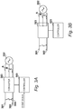
- FIGs 3A and 3B illustrate the approach adopted by the present embodiment of the electrical converter 203.
- the electric machine 202 is connected to the converter 203 via a polyphase supply.
- three phases A, B, C are connected with the converter. Being a polyphase supply, each phase is 120 degrees out-of-phase with the other two.
- the converter 203 is an active diode-clamped multilevel converter. Such a converter topology is substantially the same as a diode-clamped multilevel converter, except that the clamping diodes are connected in antiparallel with a switch to facilitate load sharing and thus prevent elevated temperatures.
- the topology of converter 203 will be described in further detail with reference to Figure 4 , and indeed such arrangements will be familiar to those skilled in the art.
- the converter 203 produces a dc output between a pair of dc rails 301 and 302.
- the converter 203 operates under the control of a controller 303, which in the present example is coupled with the switches in the converter 203 to generate a dc output from the polyphase supply.
- a controller 303 which in the present example is coupled with the switches in the converter 203 to generate a dc output from the polyphase supply.
- the controller 303 is a field-programmable gate array (FPGA) having been configured with appropriate control logic (e.g. a hardware description) to operate the converter 203.
- control logic e.g. a hardware description
- the controller 303 may instead be an application-specific integrated circuit or a microcontroller, etc.
- an event signal may be received by the controller 303.
- the generation of such event signals will be within the competence of those skilled in the art.
- the controller 303 is configured to, after receiving the event signal, enter the converter 203 into a crowbar mode of operation so as to isolate the electric machine 202 from the dc network.
- the crowbar mode of operation will be described further with reference to Figure 4 .
- the controller 303 may return the converter 203 to the normal mode of operation.
- FIG. 4 A circuit diagram of a specific embodiment of the converter 203 is shown in Figure 4 .
- the converter 203 has what is termed active diode-clamped multilevel topology.
- each clamping diode is connected in antiparallel with a switch.
- each switch in the converter 203 is provided by an insulated gate bipolar transistor (IGBT). This is due to the high levels of power produced by the electrical machine 202, which in the present embodiment is rated at 2.5 megawatts continuous for propulsion of the aircraft 101. It will be appreciated, however, that other transistors such as BJTs or MOSFETs, or indeed other types of switching devices may be used instead depending upon the intended application of the converter.
- the polyphase supply comprising phases A, B, and C are connected via a respective phase leg 401, 402, and 403 to the dc rails 301 and 302. It will be appreciated that other numbers of phases and phase legs may be implemented depending upon the configuration of the electric machine 202.
- converter 203 is a three-level converter, and so includes a dc-link capacitor comprising two series-connected capacitors 404 and 405.
- the midpoint 406 between the capacitors 404 and 405 is therefore a neutral point.
- the phase legs each include a plurality of switches composed of an IGBT-antiparallel diode pair, and which are labelled Snp, where n is the number of the switch and p is the attendant phase of the phase leg in which it is located, e.g. S1A is the upper outer IGBT-antiparallel diode pair in phase leg 401.
- Each leg includes four series-connected IGBT-antiparallel diode pairs ⁇ S1p ... S4p ⁇ , and two clamping IGBT-antiparallel diode pairs S5p and S6p.
- the controller 303 activates the required combination of switches ⁇ S1A ... S6C ⁇ to generate a dc output from the polyphase input.
- each leg has four possible combinations ⁇ 01 ... 04 ⁇ for connection of the phase to the neutral midpoint node 406.
- the well-established switch logic for this type of converter topology is set out in Table 1: Table 1 State S1p S2p S3p S4p S5p S6p + 1 1 0 0 0 1 01 0 1 0 0 1 0 02 0 1 0 1 1 0 03 1 0 1 0 0 0 1 04 0 0 1 0 0 1 - 0 0 1 1 1 0
- the electric machine 202 is optimised such that it exhibits an inductive impedance of 0.6 per-unit. Given a generated ac voltage of 1 per-unit, this would result in, unchecked, a fault current of 1.67 per-unit which would quickly cause thermal damage in the converter 203.
- the controller 303 activates a combination of switches in each phase leg 401, 402, and 403 that forms a pair of parallel conduction paths to the midpoint 406, as set out in Table 2:
- each phase A, B, C is connected to the same node and is thereby isolated from the dc network.
- FIG. 5 An alternative embodiment of the converter 203 is illustrated in Figure 5 , and is identified by reference numeral 203'. For simplicity, only one phase A and associated phase leg 501 is shown.
- the converter 203' has a five-level active diode-clamped topology and thus has a dc-link capacitor between the dc rails 301 and 302 that comprises four series-connected capacitors 502, 503, 504, 505. Three midpoints 506, 507, and 508 are therefore defined at the nodes between any adjacent two of the capacitors 502 to 505.
- phase leg 501 corresponding to phase A comprises a plurality of series-connected IGBT-antiparallel diode pairs ⁇ S1A ... S8A ⁇ which are connected between the dc rails 301 and 302.
- the connection with phase A is at a node between IGBT-antiparallel diode pairs S4A and S5A.
- Upper clamping IGBT-antiparallel diode pair S9A and S10A clamp to midpoint 506, neutral clamping IGBT-antiparallel diode pair S11A and S12A clamp to midpoint 507, and lower clamping IGBT-antiparallel diode pair S13A and S14A clamp to midpoint 508.
- This topology and its normal mode of operation will be understood by those skilled in the art and therefore will not be described further.
- the switching states C1, C2, and C3 are set out in Table 3: Table 3 State S1p S2p S3p S4p S5p S6p S7p S8p S9p S10p S11p S12p S13p S14p C1 0 1 1 1 1 0 0 0 1 1 0 0 0 0 C2 0 0 1 1 1 1 0 0 0 0 1 1 0 0 C3 0 0 0 1 1 1 1 0 0 0 0 0 1 1 1 1 1 0 0 0 0 1 1 1 1
- the controller 203 is configured to intermittently switch between the crowbar states C1, C2, and C3. This may be as part of a load balancing strategy. For example, the temperature in some of the activated IGBTs may after a certain time begin to exceed a threshold, for example due to conduction losses therein. In such a case, the present crowbar state, say C1, may be switched for another, say C2 or C3. Such a decision may be taken based upon the temperature of the devices to be activated in the other states (C2 or C3 in this example).
Landscapes
- Engineering & Computer Science (AREA)
- Power Engineering (AREA)
- Inverter Devices (AREA)
Abstract
Description
- This disclosure concerns electrical converters, which will be understood as embracing rectifiers and inverters.
- Permanent magnet electrical generators are used for their high efficiency and high power density. Their output is often supplied to a rectifier to produce a direct current output.
- One problem with permanent magnet generators is that unless they are physically stopped from rotating, they continue to drive current. This can be an issue if, in the arrangement described above, a fault occurs in the dc network. In many implementations, it is not possible to instantaneously stop the generator from being rotatably driven: either the driving apparatus has a certain degree of angular momentum, or it is not possible for safety reasons or otherwise to mechanically sever the connection between the generator and the driving apparatus.
- In such circumstances, it has been a requirement to implement a separate crowbar circuit, in which the approach is to short circuit the phases of the generator. However, such an approach imposes a severe over-current on the power electronics in the rectifier, which cannot be guaranteed to survive the process. This may not be satisfactory in circumstances where, once the dc fault is cleared, the generator is required to be re-connected to the dc network and continue to provide power.
- The invention is directed towards an electrical converter, and controllers and methods of operation therefor.
- In one aspect, an electrical converter is provided having an active diode-clamped multilevel topology in which each clamping diode is connected in antiparallel with a switch.
- The converter comprises polyphase supply phases each of which are connected via a respective phase leg to dc rails and a dc-link capacitor. The dc-link capacitor including a plurality of series-connected capacitors.
- A controller for the converter is configured to, in response to an event signal, for each phase leg, activates a combination of switches therein to form a pair of parallel conduction paths to a midpoint between two capacitors in the dc-link capacitor, thereby connecting each phase to the same node.
- In another aspect, a method of controlling such a converter is provided, comprising, for each phase leg, activates a combination of switches therein to form a pair of parallel conduction paths to a midpoint between two capacitors in the dc-link capacitor, thereby connecting each phase to the same node.
- Embodiments will now be described by way of example only with reference to the accompanying drawings, which are purely schematic and not to scale, and in which:
-
Figure 1 shows an aircraft having a series-hybrid propulsion system; -
Figure 2 is a block diagram of the series-hybrid propulsion system ofFigure 1 , which includes a generator and an electrical converter; -
Figures 3A and 3B show the generator and electrical converter ofFigure 2 and the controller for the converter; -
Figure 4 is a circuit diagram of the converter; and -
Figure 5 is a circuit diagram of an alternative embodiment of the converter. - An example application of an embodiment is illustrated in
Figure 1 . Anaircraft 101 is shown in which a series-hybrid propulsion system is employed. A pair ofelectric propulsion units 102 are installed below the wings of theaircraft 101. Theelectric propulsion units 102 are connected via apower distribution bus 103 to a source of electrical power located in the fuselage of theaircraft 101. In the present example, the source of electrical power is an internal combustion engine configured to drive an electric machine. In the specific embodiment ofFigure 1 , the source of electrical power isturboelectric generator 104, in which the internal combustion engine is a gas turbine engine. In an alternative embodiment, the internal combustion engine may be a piston engine or similar. The source of electrical power could alternatively by a fuel cell, battery, etc. - Each
electric propulsion unit 102 includes an electric machine configured to drive a propulsive fan. In the present example, theelectric propulsion units 102 are ducted fans, although it will be appreciated that in alternative embodiments theelectric propulsion units 102 may be configured as open propellers (a type of propulsive fan), or any other configuration able to produce thrust by causing a pressure rise in the incident airflow. -
Figure 2 is a block diagram of the propulsion system of the aircraft ofFigure 1 . - In the present example, therefore, a
gas turbine engine 201 drives afirst machine 202 operating as a generator via an interconnecting shaft, thus providing a source of electrical power in the form of alternating current. In the present example, the alternating current is converted to direct current for distribution on the bus by way of a firstelectrical converter 203 operating as a rectifier. - Power is drawn from the
bus 103 by a secondelectrical converter 204 operating as an inverter for supplying a secondelectric machine 205, which operates as a motor. This in turn drives apropulsive fan 206 via an interconnecting shaft, thereby providing propulsion. - It will be appreciated that depending upon the configuration of the aircraft (for example aircraft 101) further propulsive fans, electric machines and electrical converters may be provided.
- In the event of a fault in the dc part of the network, i.e. in the
bus 103, it is of course advantageous to be able to isolate theelectric machine 202 and converter 203. However, on the basis that it may be possible to clear the fault in the dc part of the network, it is a requirement that the method used to isolate theelectric machine 202 andconverter 203 be reversible. In the present example, this is to guarantee safety of theaircraft 101. Thus, theelectric machine 202 must remain drivingly connected with thegas turbine engine 201, and theconverter 203 must remain in a condition to provide continued rectification. -
Figures 3A and 3B illustrate the approach adopted by the present embodiment of theelectrical converter 203. As shown inFigure 3A , in the present embodiment theelectric machine 202 is connected to theconverter 203 via a polyphase supply. In the present example, three phases A, B, C are connected with the converter. Being a polyphase supply, each phase is 120 degrees out-of-phase with the other two. - The
converter 203 is an active diode-clamped multilevel converter. Such a converter topology is substantially the same as a diode-clamped multilevel converter, except that the clamping diodes are connected in antiparallel with a switch to facilitate load sharing and thus prevent elevated temperatures. The topology ofconverter 203 will be described in further detail with reference toFigure 4 , and indeed such arrangements will be familiar to those skilled in the art. - The
converter 203 produces a dc output between a pair ofdc rails converter 203 operates under the control of acontroller 303, which in the present example is coupled with the switches in theconverter 203 to generate a dc output from the polyphase supply. Such standard mode of operation will be understood by those skilled in the art. - In the present example, the
controller 303 is a field-programmable gate array (FPGA) having been configured with appropriate control logic (e.g. a hardware description) to operate theconverter 203. In alternative embodiments thecontroller 303 may instead be an application-specific integrated circuit or a microcontroller, etc. - In the event that a
fault 304 occurs on the dc side of theconverter 203, an event signal may be received by thecontroller 303. The generation of such event signals will be within the competence of those skilled in the art. - As illustrated in
Figure 3B , in the present example thecontroller 303 is configured to, after receiving the event signal, enter theconverter 203 into a crowbar mode of operation so as to isolate theelectric machine 202 from the dc network. The crowbar mode of operation will be described further with reference toFigure 4 . - Once the fault has been cleared, the
controller 303 may return theconverter 203 to the normal mode of operation. - A circuit diagram of a specific embodiment of the
converter 203 is shown inFigure 4 . - As described previously, the
converter 203 has what is termed active diode-clamped multilevel topology. In such an arrangement, each clamping diode is connected in antiparallel with a switch. As can be seen inFigure 4 , each switch in theconverter 203 is provided by an insulated gate bipolar transistor (IGBT). This is due to the high levels of power produced by theelectrical machine 202, which in the present embodiment is rated at 2.5 megawatts continuous for propulsion of theaircraft 101. It will be appreciated, however, that other transistors such as BJTs or MOSFETs, or indeed other types of switching devices may be used instead depending upon the intended application of the converter. - The polyphase supply comprising phases A, B, and C are connected via a
respective phase leg electric machine 202. - In the present embodiment,
converter 203 is a three-level converter, and so includes a dc-link capacitor comprising two series-connectedcapacitors midpoint 406 between thecapacitors - It will be appreciated that more than three levels may be provided in other embodiments, for example four or greater. For example, an alternative embodiment of the converter will be described in
Figure 5 , in which the converter is a five-level converter. Odd numbers of levels will result in there being one midpoint that is neutral, whilst even numbers of levels will not have a midpoint that is a neutral. - Referring again to
Figure 4 , The phase legs each include a plurality of switches composed of an IGBT-antiparallel diode pair, and which are labelled Snp, where n is the number of the switch and p is the attendant phase of the phase leg in which it is located, e.g. S1A is the upper outer IGBT-antiparallel diode pair inphase leg 401. Each leg includes four series-connected IGBT-antiparallel diode pairs {S1p ... S4p}, and two clamping IGBT-antiparallel diode pairs S5p and S6p. - In normal operation, the
controller 303 activates the required combination of switches {S1A ... S6C} to generate a dc output from the polyphase input. As will be familiar to those skilled in the art, each leg has four possible combinations {01 ... 04} for connection of the phase to theneutral midpoint node 406. The well-established switch logic for this type of converter topology is set out in Table 1:Table 1 State S1p S2p S3p S4p S5p S6p + 1 1 0 0 0 1 01 0 1 0 0 1 0 02 0 1 0 1 1 0 03 1 0 1 0 0 1 04 0 0 1 0 0 1 - 0 0 1 1 1 0 - It will be understood that these current paths are acceptable during normal operation, in terms of not exceeding the rating of the devices in the
converter 203. - However, when a fault occurs in the dc network such as described with reference to
Figure 3A , the voltage between the dc rails 301 and 302 nominally becomes zero. This results in a high continuous current flow. For example, in the present embodiment theelectric machine 202 is optimised such that it exhibits an inductive impedance of 0.6 per-unit. Given a generated ac voltage of 1 per-unit, this would result in, unchecked, a fault current of 1.67 per-unit which would quickly cause thermal damage in theconverter 203. - Thus, in order to implement a crowbar mode of operation (state C), in the present embodiment the
controller 303 activates a combination of switches in eachphase leg midpoint 406, as set out in Table 2:Table 2 State S1p S2p S3p S4p S5p S6p C 0 1 1 0 1 1 - In this way, each phase A, B, C is connected to the same node and is thereby isolated from the dc network.
- It will be appreciated that the division of current between the two parallel conduction paths means that each path only carries 0.83 per-unit current. Consequently, the
converter 203 may remain in this mode of operation indefinitely if required, as the current in any particular device is below its rating. Thus it will be appreciated that this mode of control is particularly advantageous for power conversion from electrical machines having an inductive impedance of from 0.5 to 1 per-unit. - An alternative embodiment of the
converter 203 is illustrated inFigure 5 , and is identified by reference numeral 203'. For simplicity, only one phase A and associatedphase leg 501 is shown. - The converter 203' has a five-level active diode-clamped topology and thus has a dc-link capacitor between the dc rails 301 and 302 that comprises four series-connected
capacitors midpoints capacitors 502 to 505. - In a similar way to
converter 203,phase leg 501 corresponding to phase A comprises a plurality of series-connected IGBT-antiparallel diode pairs {S1A ... S8A} which are connected between the dc rails 301 and 302. The connection with phase A is at a node between IGBT-antiparallel diode pairs S4A and S5A. Upper clamping IGBT-antiparallel diode pair S9A and S10A clamp tomidpoint 506, neutral clamping IGBT-antiparallel diode pair S11A and S12A clamp tomidpoint 507, and lower clamping IGBT-antiparallel diode pair S13A and S14A clamp tomidpoint 508. This topology and its normal mode of operation will be understood by those skilled in the art and therefore will not be described further. - There are therefore three different parallel conduction paths that may achieve crowbar operation. The switching states C1, C2, and C3 are set out in Table 3:
Table 3 State S1p S2p S3p S4p S5p S6p S7p S8p S9p S10p S11p S12p S13p S14p C1 0 1 1 1 1 0 0 0 1 1 0 0 0 0 C2 0 0 1 1 1 1 0 0 0 0 1 1 0 0 C3 0 0 0 1 1 1 1 0 0 0 0 0 1 1 - In an embodiment, the
controller 203 is configured to intermittently switch between the crowbar states C1, C2, and C3. This may be as part of a load balancing strategy. For example, the temperature in some of the activated IGBTs may after a certain time begin to exceed a threshold, for example due to conduction losses therein. In such a case, the present crowbar state, say C1, may be switched for another, say C2 or C3. Such a decision may be taken based upon the temperature of the devices to be activated in the other states (C2 or C3 in this example). - Various examples have been described, each of which feature various combinations of features. It will be appreciated by those skilled in the art that, except where clearly mutually exclusive, any of the features may be employed separately or in combination with any other features and the invention extends to and includes all combinations and subcombinations of one or more features described herein.
Claims (15)
- An electrical converter having an active diode-clamped multilevel topology in which each clamping diode is connected in antiparallel with a switch, the converter comprising:polyphase supply phases each of which are connected via a respective phase leg to dc rails and a dc-link capacitor, the dc-link capacitor including a plurality of series-connected capacitors; anda controller configured to, in response to an event signal, for each phase leg, activate a combination of switches therein to form a pair of parallel conduction paths to a midpoint between two capacitors in the dc-link capacitor, thereby connecting each phase to the same node.
- The electrical converter of claim 1, having three supply phases and three phase legs.
- The electrical converter of claim 1, in which the multilevel topology is a three-level topology wherein the dc-link capacitor comprises two series-connected capacitors such that the midpoint is a node between the two series-connected capacitors.
- The electrical converter of claim 1, in which the multilevel topology is at least a four-level topology wherein the dc-link capacitor comprises three or more series-connected capacitors such that the midpoint is a node between any adjacent two of the three or more series-connected capacitors.
- The electrical converter of claim 4, in which the controller is configured to, for each phase leg, intermittently change between combinations of switches to form different pairs of parallel conduction paths to different midpoints
- The electrical converter of claim 10, in which the controller is configured to change between combinations of switches in response to a temperature of at least one of the switches exceeding a threshold value.
- A controller for an electrical converter of the type having an active diode-clamped multilevel topology in which each clamping diode is connected in antiparallel with a switch, and polyphase supply phases each of which are connected via a respective phase leg to dc rails and a dc-link capacitor, the dc-link capacitor including a plurality of series-connected capacitors;
the controller being configured to, in response to an event signal, for each phase leg in the converter, activate a combination of switches therein to form a pair of parallel conduction paths to a midpoint between two capacitors in the dc-link capacitor, thereby connecting each phase to the same node. - The controller of claim 7, in which the multilevel topology is a three-level topology wherein the dc-link capacitor comprises two series-connected capacitors such that the midpoint is a node between the two series-connected capacitors.
- The controller of claim 7, in which the multilevel topology is a four-or-higher-level topology wherein the dc-link capacitor comprises three or more series-connected capacitors such that the midpoint is a node between any adjacent two of the three or more series-connected capacitors.
- The controller of claim 9, further configured to, for each phase leg, intermittently change between combinations of switches to form different pairs of parallel conduction paths to different midpoints
- The controller of claim 10, in which the controller is configured to change between combinations of switches in response to a temperature of at least one of the switches exceeding a threshold value.
- A method of operating an electrical converter of the type having an active diode-clamped multilevel topology in which each clamping diode is connected in antiparallel with a switch, and polyphase supply phases each of which are connected via a respective phase leg to dc rails and a dc-link capacitor, the dc-link capacitor including a plurality of series-connected capacitors;
the method comprising, for each phase leg in the converter, activating a combination of switches therein to form a pair of parallel conduction paths to a midpoint between two capacitors in the dc-link capacitor, thereby connecting each phase to the same node. - The method of claim 12, in which the multilevel topology is a three-level topology wherein the dc-link capacitor comprises two series-connected capacitors such that the midpoint is a node between the two series-connected capacitors.
- The method of claim 12, in which the multilevel topology is a four-or-higher-level topology wherein the dc-link capacitor comprises three or more series-connected capacitors such that the midpoint is a node between any adjacent two of the three or more series-connected capacitors.
- The method of claim 14, further comprising, for each phase leg, intermittently changing between combinations of switches to form different pairs of parallel conduction paths to different midpoints, optionally in response to a temperature of at least one of the switches exceeding a threshold value.
Applications Claiming Priority (1)
| Application Number | Priority Date | Filing Date | Title |
|---|---|---|---|
| GBGB1815301.5A GB201815301D0 (en) | 2018-09-20 | 2018-09-20 | Converter |
Publications (2)
| Publication Number | Publication Date |
|---|---|
| EP3627645A1 true EP3627645A1 (en) | 2020-03-25 |
| EP3627645B1 EP3627645B1 (en) | 2025-02-19 |
Family
ID=64024353
Family Applications (1)
| Application Number | Title | Priority Date | Filing Date |
|---|---|---|---|
| EP19192472.9A Active EP3627645B1 (en) | 2018-09-20 | 2019-08-20 | Converter |
Country Status (4)
| Country | Link |
|---|---|
| US (1) | US11063527B2 (en) |
| EP (1) | EP3627645B1 (en) |
| CN (1) | CN110932536B (en) |
| GB (1) | GB201815301D0 (en) |
Cited By (1)
| Publication number | Priority date | Publication date | Assignee | Title |
|---|---|---|---|---|
| EP3961886A1 (en) * | 2020-08-24 | 2022-03-02 | General Electric Company | Crowbar module for an active neutral point clamped power conversion assembly |
Families Citing this family (3)
| Publication number | Priority date | Publication date | Assignee | Title |
|---|---|---|---|---|
| CN112003490B (en) * | 2020-07-31 | 2021-06-04 | 北京金风科创风电设备有限公司 | Power components of three-level converters and three-level converters |
| BR112022001041A2 (en) * | 2021-01-19 | 2022-10-18 | Huawei Digital Power Tech Co Ltd | PHOTOVOLTAIC ENERGY GENERATION SYSTEM, AND METHOD TO CONTROL FAILURE PROTECTION DEVICES |
| US12244244B2 (en) * | 2022-04-28 | 2025-03-04 | General Electric Renovables Espana, S.L. | Fault tolerant system and method for continuous skip-fire pulse width modulation for an active neutral point clamped converter |
Citations (3)
| Publication number | Priority date | Publication date | Assignee | Title |
|---|---|---|---|---|
| WO2002031956A1 (en) * | 2000-10-11 | 2002-04-18 | Abb Ab | A method for controlling a vsc-converter and a vsc-converter |
| US20060056209A1 (en) * | 2002-10-09 | 2006-03-16 | Ingemar Blidberg | Converter and a method for controlling a converter |
| WO2015148977A1 (en) * | 2014-03-27 | 2015-10-01 | General Electric Company | System and method for direct current power transmission |
Family Cites Families (15)
| Publication number | Priority date | Publication date | Assignee | Title |
|---|---|---|---|---|
| JP3179951B2 (en) | 1993-12-27 | 2001-06-25 | 三菱電機株式会社 | Power converter |
| US6459596B1 (en) * | 2000-08-18 | 2002-10-01 | The United States Of America As Represented By The Secretary Of The Navy | Method and apparatus for a Reduced parts-counts multilevel rectifier |
| SE521164C2 (en) | 2002-02-13 | 2003-10-07 | Abb Ab | Voltage source convertor current rectifier is of three level type, with four series-coupled current valves and two units connected on one hand between point between one outer valve in series coupling and nearest inner valve |
| US20070223258A1 (en) * | 2003-11-25 | 2007-09-27 | Jih-Sheng Lai | Multilevel converters for intelligent high-voltage transformers |
| US7495938B2 (en) * | 2005-04-15 | 2009-02-24 | Rockwell Automation Technologies, Inc. | DC voltage balance control for three-level NPC power converters with even-order harmonic elimination scheme |
| US8228695B2 (en) * | 2009-11-16 | 2012-07-24 | General Electric Company | Multilevel converter operation |
| JP6087531B2 (en) * | 2012-08-06 | 2017-03-01 | 三菱電機株式会社 | Power converter |
| CN104798297B (en) * | 2012-11-21 | 2018-04-17 | 奥的斯电梯公司 | The more level translators of neutral-point-clamped |
| US9083230B2 (en) * | 2013-06-20 | 2015-07-14 | Rockwell Automation Technologies, Inc. | Multilevel voltage source converters and systems |
| JP6075224B2 (en) * | 2013-06-25 | 2017-02-08 | 株式会社明電舎 | Multi-level power converter |
| CN104362923B (en) | 2014-11-05 | 2017-02-01 | 东南大学 | Decoupling SVPWM (space vector pulse width modulation) based fault tolerance control method for open-winding PMSM (permanent magnet synchronous motor) driving system |
| CN104883084B (en) * | 2015-05-26 | 2017-10-03 | 清华大学 | A kind of neutral point clamp type cascaded H-bridges mixed multi-level current transformer |
| JP6711185B2 (en) * | 2016-07-13 | 2020-06-17 | オムロン株式会社 | Power converter |
| US10181813B2 (en) * | 2016-10-27 | 2019-01-15 | Power Integrations, Inc. | Half-bridge inverter modules with advanced protection through high-side to low-side control block communication |
| US10770987B2 (en) * | 2018-05-11 | 2020-09-08 | Hamilton Sunstrand Corporation | Motor drive architecture for variable frequency alternating current loads |
-
2018
- 2018-09-20 GB GBGB1815301.5A patent/GB201815301D0/en not_active Ceased
-
2019
- 2019-08-20 EP EP19192472.9A patent/EP3627645B1/en active Active
- 2019-09-13 US US16/570,739 patent/US11063527B2/en active Active
- 2019-09-20 CN CN201910892537.6A patent/CN110932536B/en active Active
Patent Citations (3)
| Publication number | Priority date | Publication date | Assignee | Title |
|---|---|---|---|---|
| WO2002031956A1 (en) * | 2000-10-11 | 2002-04-18 | Abb Ab | A method for controlling a vsc-converter and a vsc-converter |
| US20060056209A1 (en) * | 2002-10-09 | 2006-03-16 | Ingemar Blidberg | Converter and a method for controlling a converter |
| WO2015148977A1 (en) * | 2014-03-27 | 2015-10-01 | General Electric Company | System and method for direct current power transmission |
Cited By (2)
| Publication number | Priority date | Publication date | Assignee | Title |
|---|---|---|---|---|
| EP3961886A1 (en) * | 2020-08-24 | 2022-03-02 | General Electric Company | Crowbar module for an active neutral point clamped power conversion assembly |
| US11843325B2 (en) | 2020-08-24 | 2023-12-12 | General Electric Company | Crowbar module for an active neutral point clamped power conversion assembly |
Also Published As
| Publication number | Publication date |
|---|---|
| EP3627645B1 (en) | 2025-02-19 |
| GB201815301D0 (en) | 2018-11-07 |
| CN110932536B (en) | 2024-04-09 |
| CN110932536A (en) | 2020-03-27 |
| US11063527B2 (en) | 2021-07-13 |
| US20200099312A1 (en) | 2020-03-26 |
Similar Documents
| Publication | Publication Date | Title |
|---|---|---|
| US12028009B2 (en) | Protection system for aircraft electric propulsion motor and motor controller | |
| EP3627645B1 (en) | Converter | |
| Kouro et al. | Powering the future of industry: High-power adjustable speed drive topologies | |
| US9036379B2 (en) | Power converter based on H-bridges | |
| CN102939714B (en) | Voltage inverter and method of controlling such an inverter | |
| US7026783B2 (en) | Drive system | |
| EP2006993A2 (en) | 7-level wye-connected H-bridge converter topology for powering a high-speed electric motor | |
| CN106471724A (en) | There is the current transformer of the circuit topology of redundancy | |
| US12015333B2 (en) | Intelligent discharge control for modular multilevel converter | |
| Lee et al. | Review on switching device fault, protection, and fault-tolerant topologies of current source inverter | |
| Zhang et al. | Fault analysis and fault-tolerant design for parallel redundant inverter systems in case of IGBT short-circuit failures | |
| Ugur et al. | Design of a GaN based integrated modular motor drive | |
| Grandi et al. | Fault-tolerant control strategies for quad inverter induction motor drives with one failed inverter | |
| Tian et al. | Commutation scheme of seven-level hybrid-clamped converters with suppressed deadband-induced voltage spikes | |
| Di Benedetto et al. | Five-level back to back E-Type converter for high speed gen-set applications | |
| Yeh et al. | Induction motor-drive systems with fault tolerant inverter-motor capabilities | |
| Farnesi et al. | A new fault tolerant NPC converter system for high power induction motor drives | |
| CN116937997A (en) | System and method for detecting IGBT failure using gate-emitter voltage sensing | |
| Alosa et al. | Reconfigurable multi-three-phase propulsion system for naval rim-driven propeller | |
| Salehifar et al. | Fault tolerant operation of a five phase converter for PMSM drives | |
| Shakweh | New breed of medium voltage converters | |
| Grandi et al. | Fault-tolerant operating analysis of a quad-inverter multiphase multilevel AC motor drive | |
| Cordeiro et al. | Combining mechanical commutators and semiconductors in fast changing redundant inverter topologies | |
| Wu et al. | Six-phase fault-tolerant permanent magnet motor drives with reduced switch counts: Topology comparisons and hardware demonstration | |
| Mohamadian et al. | Improving fault tolerance of multiphase lci-fed synchronous motor drives |
Legal Events
| Date | Code | Title | Description |
|---|---|---|---|
| PUAI | Public reference made under article 153(3) epc to a published international application that has entered the european phase |
Free format text: ORIGINAL CODE: 0009012 |
|
| STAA | Information on the status of an ep patent application or granted ep patent |
Free format text: STATUS: THE APPLICATION HAS BEEN PUBLISHED |
|
| AK | Designated contracting states |
Kind code of ref document: A1 Designated state(s): AL AT BE BG CH CY CZ DE DK EE ES FI FR GB GR HR HU IE IS IT LI LT LU LV MC MK MT NL NO PL PT RO RS SE SI SK SM TR |
|
| AX | Request for extension of the european patent |
Extension state: BA ME |
|
| STAA | Information on the status of an ep patent application or granted ep patent |
Free format text: STATUS: REQUEST FOR EXAMINATION WAS MADE |
|
| 17P | Request for examination filed |
Effective date: 20200924 |
|
| RBV | Designated contracting states (corrected) |
Designated state(s): AL AT BE BG CH CY CZ DE DK EE ES FI FR GB GR HR HU IE IS IT LI LT LU LV MC MK MT NL NO PL PT RO RS SE SI SK SM TR |
|
| STAA | Information on the status of an ep patent application or granted ep patent |
Free format text: STATUS: EXAMINATION IS IN PROGRESS |
|
| 17Q | First examination report despatched |
Effective date: 20220221 |
|
| GRAP | Despatch of communication of intention to grant a patent |
Free format text: ORIGINAL CODE: EPIDOSNIGR1 |
|
| STAA | Information on the status of an ep patent application or granted ep patent |
Free format text: STATUS: GRANT OF PATENT IS INTENDED |
|
| GRAS | Grant fee paid |
Free format text: ORIGINAL CODE: EPIDOSNIGR3 |
|
| GRAA | (expected) grant |
Free format text: ORIGINAL CODE: 0009210 |
|
| STAA | Information on the status of an ep patent application or granted ep patent |
Free format text: STATUS: THE PATENT HAS BEEN GRANTED |
|
| INTG | Intention to grant announced |
Effective date: 20241219 |
|
| P01 | Opt-out of the competence of the unified patent court (upc) registered |
Free format text: CASE NUMBER: APP_237/2025 Effective date: 20250103 |
|
| AK | Designated contracting states |
Kind code of ref document: B1 Designated state(s): AL AT BE BG CH CY CZ DE DK EE ES FI FR GB GR HR HU IE IS IT LI LT LU LV MC MK MT NL NO PL PT RO RS SE SI SK SM TR |
|
| REG | Reference to a national code |
Ref country code: GB Ref legal event code: FG4D |
|
| REG | Reference to a national code |
Ref country code: CH Ref legal event code: EP |
|
| REG | Reference to a national code |
Ref country code: IE Ref legal event code: FG4D |
|
| REG | Reference to a national code |
Ref country code: DE Ref legal event code: R096 Ref document number: 602019066070 Country of ref document: DE |
|
| REG | Reference to a national code |
Ref country code: NL Ref legal event code: MP Effective date: 20250219 |
|
| PG25 | Lapsed in a contracting state [announced via postgrant information from national office to epo] |
Ref country code: RS Free format text: LAPSE BECAUSE OF FAILURE TO SUBMIT A TRANSLATION OF THE DESCRIPTION OR TO PAY THE FEE WITHIN THE PRESCRIBED TIME-LIMIT Effective date: 20250519 |
|
| PG25 | Lapsed in a contracting state [announced via postgrant information from national office to epo] |
Ref country code: FI Free format text: LAPSE BECAUSE OF FAILURE TO SUBMIT A TRANSLATION OF THE DESCRIPTION OR TO PAY THE FEE WITHIN THE PRESCRIBED TIME-LIMIT Effective date: 20250219 |
|
| PG25 | Lapsed in a contracting state [announced via postgrant information from national office to epo] |
Ref country code: PL Free format text: LAPSE BECAUSE OF FAILURE TO SUBMIT A TRANSLATION OF THE DESCRIPTION OR TO PAY THE FEE WITHIN THE PRESCRIBED TIME-LIMIT Effective date: 20250219 |
|
| PG25 | Lapsed in a contracting state [announced via postgrant information from national office to epo] |
Ref country code: ES Free format text: LAPSE BECAUSE OF FAILURE TO SUBMIT A TRANSLATION OF THE DESCRIPTION OR TO PAY THE FEE WITHIN THE PRESCRIBED TIME-LIMIT Effective date: 20250219 |
|
| REG | Reference to a national code |
Ref country code: LT Ref legal event code: MG9D |
|
| PG25 | Lapsed in a contracting state [announced via postgrant information from national office to epo] |
Ref country code: IS Free format text: LAPSE BECAUSE OF FAILURE TO SUBMIT A TRANSLATION OF THE DESCRIPTION OR TO PAY THE FEE WITHIN THE PRESCRIBED TIME-LIMIT Effective date: 20250619 Ref country code: NO Free format text: LAPSE BECAUSE OF FAILURE TO SUBMIT A TRANSLATION OF THE DESCRIPTION OR TO PAY THE FEE WITHIN THE PRESCRIBED TIME-LIMIT Effective date: 20250519 |
|
| PG25 | Lapsed in a contracting state [announced via postgrant information from national office to epo] |
Ref country code: NL Free format text: LAPSE BECAUSE OF FAILURE TO SUBMIT A TRANSLATION OF THE DESCRIPTION OR TO PAY THE FEE WITHIN THE PRESCRIBED TIME-LIMIT Effective date: 20250219 |
|
| PG25 | Lapsed in a contracting state [announced via postgrant information from national office to epo] |
Ref country code: HR Free format text: LAPSE BECAUSE OF FAILURE TO SUBMIT A TRANSLATION OF THE DESCRIPTION OR TO PAY THE FEE WITHIN THE PRESCRIBED TIME-LIMIT Effective date: 20250219 |
|
| PG25 | Lapsed in a contracting state [announced via postgrant information from national office to epo] |
Ref country code: LV Free format text: LAPSE BECAUSE OF FAILURE TO SUBMIT A TRANSLATION OF THE DESCRIPTION OR TO PAY THE FEE WITHIN THE PRESCRIBED TIME-LIMIT Effective date: 20250219 Ref country code: PT Free format text: LAPSE BECAUSE OF FAILURE TO SUBMIT A TRANSLATION OF THE DESCRIPTION OR TO PAY THE FEE WITHIN THE PRESCRIBED TIME-LIMIT Effective date: 20250620 |
|
| PG25 | Lapsed in a contracting state [announced via postgrant information from national office to epo] |
Ref country code: GR Free format text: LAPSE BECAUSE OF FAILURE TO SUBMIT A TRANSLATION OF THE DESCRIPTION OR TO PAY THE FEE WITHIN THE PRESCRIBED TIME-LIMIT Effective date: 20250520 Ref country code: BG Free format text: LAPSE BECAUSE OF FAILURE TO SUBMIT A TRANSLATION OF THE DESCRIPTION OR TO PAY THE FEE WITHIN THE PRESCRIBED TIME-LIMIT Effective date: 20250219 |
|
| REG | Reference to a national code |
Ref country code: AT Ref legal event code: MK05 Ref document number: 1769275 Country of ref document: AT Kind code of ref document: T Effective date: 20250219 |
|
| PG25 | Lapsed in a contracting state [announced via postgrant information from national office to epo] |
Ref country code: SE Free format text: LAPSE BECAUSE OF FAILURE TO SUBMIT A TRANSLATION OF THE DESCRIPTION OR TO PAY THE FEE WITHIN THE PRESCRIBED TIME-LIMIT Effective date: 20250219 |
|
| PG25 | Lapsed in a contracting state [announced via postgrant information from national office to epo] |
Ref country code: SM Free format text: LAPSE BECAUSE OF FAILURE TO SUBMIT A TRANSLATION OF THE DESCRIPTION OR TO PAY THE FEE WITHIN THE PRESCRIBED TIME-LIMIT Effective date: 20250219 |
|
| PG25 | Lapsed in a contracting state [announced via postgrant information from national office to epo] |
Ref country code: DK Free format text: LAPSE BECAUSE OF FAILURE TO SUBMIT A TRANSLATION OF THE DESCRIPTION OR TO PAY THE FEE WITHIN THE PRESCRIBED TIME-LIMIT Effective date: 20250219 |
|
| PGFP | Annual fee paid to national office [announced via postgrant information from national office to epo] |
Ref country code: DE Payment date: 20250827 Year of fee payment: 7 |
|
| PG25 | Lapsed in a contracting state [announced via postgrant information from national office to epo] |
Ref country code: IT Free format text: LAPSE BECAUSE OF FAILURE TO SUBMIT A TRANSLATION OF THE DESCRIPTION OR TO PAY THE FEE WITHIN THE PRESCRIBED TIME-LIMIT Effective date: 20250219 |
|
| PGFP | Annual fee paid to national office [announced via postgrant information from national office to epo] |
Ref country code: GB Payment date: 20250826 Year of fee payment: 7 |
|
| PG25 | Lapsed in a contracting state [announced via postgrant information from national office to epo] |
Ref country code: AT Free format text: LAPSE BECAUSE OF FAILURE TO SUBMIT A TRANSLATION OF THE DESCRIPTION OR TO PAY THE FEE WITHIN THE PRESCRIBED TIME-LIMIT Effective date: 20250219 |
|
| PGFP | Annual fee paid to national office [announced via postgrant information from national office to epo] |
Ref country code: FR Payment date: 20250825 Year of fee payment: 7 |
|
| PG25 | Lapsed in a contracting state [announced via postgrant information from national office to epo] |
Ref country code: EE Free format text: LAPSE BECAUSE OF FAILURE TO SUBMIT A TRANSLATION OF THE DESCRIPTION OR TO PAY THE FEE WITHIN THE PRESCRIBED TIME-LIMIT Effective date: 20250219 Ref country code: CZ Free format text: LAPSE BECAUSE OF FAILURE TO SUBMIT A TRANSLATION OF THE DESCRIPTION OR TO PAY THE FEE WITHIN THE PRESCRIBED TIME-LIMIT Effective date: 20250219 |
|
| PG25 | Lapsed in a contracting state [announced via postgrant information from national office to epo] |
Ref country code: RO Free format text: LAPSE BECAUSE OF FAILURE TO SUBMIT A TRANSLATION OF THE DESCRIPTION OR TO PAY THE FEE WITHIN THE PRESCRIBED TIME-LIMIT Effective date: 20250219 |
|
| PG25 | Lapsed in a contracting state [announced via postgrant information from national office to epo] |
Ref country code: SK Free format text: LAPSE BECAUSE OF FAILURE TO SUBMIT A TRANSLATION OF THE DESCRIPTION OR TO PAY THE FEE WITHIN THE PRESCRIBED TIME-LIMIT Effective date: 20250219 |
|
| REG | Reference to a national code |
Ref country code: DE Ref legal event code: R097 Ref document number: 602019066070 Country of ref document: DE |
|
| PLBE | No opposition filed within time limit |
Free format text: ORIGINAL CODE: 0009261 |
|
| STAA | Information on the status of an ep patent application or granted ep patent |
Free format text: STATUS: NO OPPOSITION FILED WITHIN TIME LIMIT |
|
| REG | Reference to a national code |
Ref country code: CH Ref legal event code: L10 Free format text: ST27 STATUS EVENT CODE: U-0-0-L10-L00 (AS PROVIDED BY THE NATIONAL OFFICE) Effective date: 20251231 |
|
| 26N | No opposition filed |
Effective date: 20251120 |
|
| REG | Reference to a national code |
Ref country code: CH Ref legal event code: H13 Free format text: ST27 STATUS EVENT CODE: U-0-0-H10-H13 (AS PROVIDED BY THE NATIONAL OFFICE) Effective date: 20260324 |
|
| PG25 | Lapsed in a contracting state [announced via postgrant information from national office to epo] |
Ref country code: MC Free format text: LAPSE BECAUSE OF FAILURE TO SUBMIT A TRANSLATION OF THE DESCRIPTION OR TO PAY THE FEE WITHIN THE PRESCRIBED TIME-LIMIT Effective date: 20250219 |
|
| PG25 | Lapsed in a contracting state [announced via postgrant information from national office to epo] |
Ref country code: LU Free format text: LAPSE BECAUSE OF NON-PAYMENT OF DUE FEES Effective date: 20250820 |
|
| PG25 | Lapsed in a contracting state [announced via postgrant information from national office to epo] |
Ref country code: CH Free format text: LAPSE BECAUSE OF NON-PAYMENT OF DUE FEES Effective date: 20250831 |