EP3627584B1 - Battery pack and method of manufacturing the same - Google Patents
Battery pack and method of manufacturing the same Download PDFInfo
- Publication number
- EP3627584B1 EP3627584B1 EP18895603.1A EP18895603A EP3627584B1 EP 3627584 B1 EP3627584 B1 EP 3627584B1 EP 18895603 A EP18895603 A EP 18895603A EP 3627584 B1 EP3627584 B1 EP 3627584B1
- Authority
- EP
- European Patent Office
- Prior art keywords
- bar
- protrusions
- depressions
- battery pack
- battery
- Prior art date
- Legal status (The legal status is an assumption and is not a legal conclusion. Google has not performed a legal analysis and makes no representation as to the accuracy of the status listed.)
- Active
Links
Images







Classifications
-
- H—ELECTRICITY
- H01—ELECTRIC ELEMENTS
- H01M—PROCESSES OR MEANS, e.g. BATTERIES, FOR THE DIRECT CONVERSION OF CHEMICAL ENERGY INTO ELECTRICAL ENERGY
- H01M50/00—Constructional details or processes of manufacture of the non-active parts of electrochemical cells other than fuel cells, e.g. hybrid cells
- H01M50/20—Mountings; Secondary casings or frames; Racks, modules or packs; Suspension devices; Shock absorbers; Transport or carrying devices; Holders
- H01M50/249—Mountings; Secondary casings or frames; Racks, modules or packs; Suspension devices; Shock absorbers; Transport or carrying devices; Holders specially adapted for aircraft or vehicles, e.g. cars or trains
-
- H—ELECTRICITY
- H01—ELECTRIC ELEMENTS
- H01M—PROCESSES OR MEANS, e.g. BATTERIES, FOR THE DIRECT CONVERSION OF CHEMICAL ENERGY INTO ELECTRICAL ENERGY
- H01M50/00—Constructional details or processes of manufacture of the non-active parts of electrochemical cells other than fuel cells, e.g. hybrid cells
- H01M50/20—Mountings; Secondary casings or frames; Racks, modules or packs; Suspension devices; Shock absorbers; Transport or carrying devices; Holders
-
- H—ELECTRICITY
- H01—ELECTRIC ELEMENTS
- H01M—PROCESSES OR MEANS, e.g. BATTERIES, FOR THE DIRECT CONVERSION OF CHEMICAL ENERGY INTO ELECTRICAL ENERGY
- H01M50/00—Constructional details or processes of manufacture of the non-active parts of electrochemical cells other than fuel cells, e.g. hybrid cells
- H01M50/20—Mountings; Secondary casings or frames; Racks, modules or packs; Suspension devices; Shock absorbers; Transport or carrying devices; Holders
- H01M50/204—Racks, modules or packs for multiple batteries or multiple cells
- H01M50/207—Racks, modules or packs for multiple batteries or multiple cells characterised by their shape
- H01M50/209—Racks, modules or packs for multiple batteries or multiple cells characterised by their shape adapted for prismatic or rectangular cells
-
- H—ELECTRICITY
- H01—ELECTRIC ELEMENTS
- H01M—PROCESSES OR MEANS, e.g. BATTERIES, FOR THE DIRECT CONVERSION OF CHEMICAL ENERGY INTO ELECTRICAL ENERGY
- H01M10/00—Secondary cells; Manufacture thereof
- H01M10/60—Heating or cooling; Temperature control
- H01M10/62—Heating or cooling; Temperature control specially adapted for specific applications
- H01M10/625—Vehicles
-
- H—ELECTRICITY
- H01—ELECTRIC ELEMENTS
- H01M—PROCESSES OR MEANS, e.g. BATTERIES, FOR THE DIRECT CONVERSION OF CHEMICAL ENERGY INTO ELECTRICAL ENERGY
- H01M50/00—Constructional details or processes of manufacture of the non-active parts of electrochemical cells other than fuel cells, e.g. hybrid cells
- H01M50/20—Mountings; Secondary casings or frames; Racks, modules or packs; Suspension devices; Shock absorbers; Transport or carrying devices; Holders
- H01M50/262—Mountings; Secondary casings or frames; Racks, modules or packs; Suspension devices; Shock absorbers; Transport or carrying devices; Holders with fastening means, e.g. locks
- H01M50/264—Mountings; Secondary casings or frames; Racks, modules or packs; Suspension devices; Shock absorbers; Transport or carrying devices; Holders with fastening means, e.g. locks for cells or batteries, e.g. straps, tie rods or peripheral frames
-
- H—ELECTRICITY
- H01—ELECTRIC ELEMENTS
- H01M—PROCESSES OR MEANS, e.g. BATTERIES, FOR THE DIRECT CONVERSION OF CHEMICAL ENERGY INTO ELECTRICAL ENERGY
- H01M2220/00—Batteries for particular applications
- H01M2220/20—Batteries in motive systems, e.g. vehicle, ship, plane
-
- Y—GENERAL TAGGING OF NEW TECHNOLOGICAL DEVELOPMENTS; GENERAL TAGGING OF CROSS-SECTIONAL TECHNOLOGIES SPANNING OVER SEVERAL SECTIONS OF THE IPC; TECHNICAL SUBJECTS COVERED BY FORMER USPC CROSS-REFERENCE ART COLLECTIONS [XRACs] AND DIGESTS
- Y02—TECHNOLOGIES OR APPLICATIONS FOR MITIGATION OR ADAPTATION AGAINST CLIMATE CHANGE
- Y02E—REDUCTION OF GREENHOUSE GAS [GHG] EMISSIONS, RELATED TO ENERGY GENERATION, TRANSMISSION OR DISTRIBUTION
- Y02E60/00—Enabling technologies; Technologies with a potential or indirect contribution to GHG emissions mitigation
- Y02E60/10—Energy storage using batteries
Definitions
- the present invention relates to a battery pack and a manufacturing method thereof, and particularly, it relates to a battery pack including a fixing structure for mounting a battery module and a manufacturing method thereof.
- the rechargeable batteries are gaining much attention as energy sources for power-based devices such as electric bicycles, electric vehicles, and hybrid electric vehicles in addition to mobile devices such as mobile phones, digital cameras, and laptops.
- Small battery packs to which a single battery cell is packed are used in small devices such as cellular phones and cameras, and mid-sized or large battery packs to which a battery module or a battery pack having two or more battery cells connected in parallel and/or in series are packed are used in mid-sized/large devices such as laptops and electric vehicles.
- a battery pack is configured by connecting a plurality of battery cells, in a general way, a battery module including a plurality of battery cells is configured, a battery module assembly including a plurality of battery modules is configured, and the battery pack is configured by adding other constituent elements to the battery module assembly. Therefore, when the battery pack is configured, electrical connection and mechanical connection among a plurality of battery modules may determine a shape of a battery module assembly.
- FIG. 1 shows a battery pack structure according to prior art.
- rigidity of the battery pack structure may be improved by arranging a plurality of battery modules 110 on a pack tray 100, mounting the same on the pack tray 100 through a mounting bolt 130, and forming an impact absorbing column 120 between the neighboring battery modules 110.
- an additional space for the mounting bolt 130 is needed, and there is a limit in improving energy density of the battery pack because of a space occupied by the impact absorbing column 120.
- the present invention has been made in an effort to provide a battery pack for reinforcing rigidity of a battery pack without an additional space for mounting and fixing a battery module, and a manufacturing method thereof.
- the present invention provides a battery pack as defined in independent claim 1 and a method for manufacturing a battery pack as defined in independent claim 9; preferred embodiments are defined in dependent claims 2-8 and 10-12.
- the lateral plate of the battery module is assembled to the x bar (X-bar) of the battery pack, so that the battery module may be mounted on the battery pack and the lateral plate may function as an impact absorbing column of the battery pack.
- the x bar of the battery pack is separated into two pieces to thus reinforce rigidity of the battery pack and simultaneously fix the battery module.
- FIG. 2 shows a perspective view of a battery pack according to an exemplary embodiment of the present invention.
- the battery pack according to an exemplary embodiment of the present invention includes a plurality of battery modules 210a and 210b provided on a pack tray 200.
- Battery modules 210a and 210b are shown in FIG. 2 , and regarding the battery pack according to the present exemplary embodiment, six battery modules 210a and 210b are respectively disposed in two rows in a y direction on the pack tray 200.
- a plurality of battery modules 210a and 210b have a structure in which six of them are arranged in two rows, and the structure of the two rows and six columns is modifiable according to required capacity and a target structure in which the battery pack is mounted.
- the battery module includes at least two battery cells.
- a first x bar 230a and a second x bar 230b are disposed between the battery modules 210a and 210b of the respective rows, and a plurality of lateral plates 220 cover lateral sides of the battery modules 210a and 210b.
- the plurality of lateral plates 220 are separated with respect to the first x bar 230a and the second x bar 230b.
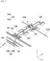
- FIG. 3 shows a partial perspective view of part of a battery pack shown in FIG. 2 .
- FIG. 4 shows an exploded view of a battery pack of FIG. 2 from which one row of battery modules are removed.
- a lateral side of the battery module 210 according to the present exemplary embodiment is covered with a plurality of lateral plates 220. This will be described in detail later in a description of a method for manufacturing a battery pack.
- FIG. 3 shows a part of a boundary region where battery modules 210a and 210b neighboring each other from among a plurality of battery modules meet.
- an x bar 230 including a first x bar 230a and a second x bar 230b is provided between the first battery module 210a and the second battery module 210b neighboring each other.
- the first x bar 230a lengthily extends in the y-axis direction
- the second x bar 230b is disposed on the first x bar 230a and extends to overlap the first x bar 230a and in parallel to the same.
- first x bar 230a and the second x bar 230b overlap each other in the z-axis direction, and they have a bar shape lengthily extending in the y-axis direction.
- the first x bar 230a has a " ⁇ " shape
- the second x bar 230b has a " " shape.
- the first x bar 230a and the second x bar 230b are combined by a plurality of fastening members 250.
- the fastening member 250 may be configured by a bolt fastening structure.
- the lateral plate 220 forms a concave and convex structure with the " ⁇ " shaped first x bar 230a and/or the " " shaped second x bar 230b, and the lateral plate 220 is assembled to the first x bar 230a and/or the second x bar 230b through the structure. Therefore, through the structure of mounting the battery module on the battery pack, the lateral plate 220 may function as a plurality of impact absorbing columns previously formed to improve rigidity of the battery pack structure.
- FIG. 5 shows a cross-sectional view with respect to a line A-A of FIG. 3 .
- the fastening member 250 may include a bolt penetrating through the second x bar 230b and passing through at least part of the first x bar 230a.
- FIG. 6 shows a front view seen in an F direction of FIG. 3 .
- FIG. 7 shows a partial perspective view of a lateral plate of a battery pack according to an exemplary embodiment of the present invention.
- a ring-shaped protrusion is formed on at least one of respective edges of an end of the lateral plate 220 so as to be combined to respective sides of the first x bar 230a and respective sides of the second x bar 230b.
- respective edges of an end of the lateral plate 220 and the first x bar 230a form protrusions and depressions 235a and 235b
- respective edges of an end of the lateral plate 220 and the second x bar 230b form protrusions and depressions 235c and 235d.
- At least one of the protrusions and depressions 235 is formed on a portion where the end of the lateral plate 220 meets the first x bar 230a and/or a portion where the end of the lateral plate 220 meets the second x bar 230b.
- FIG. 6 shows a plurality of protrusions and depressions 235 including first protrusions and depressions 235a and second protrusions and depressions 235b formed by protrusions respectively formed on bottoms of ends of two lateral plates 220 neighboring each other with recess portions formed on respective sides of the first x bar 230a and the first x bar 230a, and third protrusions and depressions 235c and fourth protrusions and depressions 235d formed by protrusions respectively formed on recess portions respectively formed on respective sides of the second x bar 230b and tops of ends of two lateral plates 220 neighboring each other.
- the protrusions and depressions 235 function to mount the battery module on the battery pack by assembling of the lateral plate 220 and the first x bar 230a and/or the second x bar 230b, and it is preferable, as shown in FIG. 6 , to form a total of four protrusions and depressions 235 or at least four protrusions and depressions 235 on a portion in which respective edges of ends of the lateral plate 220 meet the first x bar 230a and the second x bar 230b so as to improve fixation.
- a protrusions and depressions structure may be formed between one of the first x bar 230a and the second x bar 230b and the lateral plate 220 and it may not be formed between the other thereof and the lateral plate 220 as a modified example.
- a rightmost portion corresponds to an end of the lateral plate 220, and protrusions 234 are respectively formed on respective edges of ends of the lateral plate 220.
- the protrusion 234 combines with the recess portions formed on the left side and the right side of the first x bar 230a and the second x bar 230b shown in FIG. 6 to form the protrusions and depressions 235.
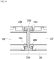
- FIG. 7 As an exemplary variation of the structure of the protrusions and depressions 235, referring to FIG.
- recess portions are respectively formed on respective edges of ends of a lateral plate 220', and protrusions combined thereto may be formed on the left side and the right side of a first x bar 230a' and a second x bar 230b'.
- the above-described battery pack may be applied to various devices.
- the devices are applicable to transportation means such as electric bicycles, electric vehicles, or hybrid vehicles, and without being limited thereto, they may be applied to various devices using a battery pack.
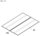
- FIG. 9 through FIG. 13 show perspective views of a method for manufacturing a battery pack according to an exemplary embodiment of the present invention.
- a " ⁇ " shaped first x bar 230a is attached to the pack tray 200.
- the first x bar 230a may be attached to the pack tray 200 by welding.
- a plurality of openings are formed in the first x bar 230a.
- a plurality of lateral plates 220 are disposed on the pack tray 200 to partition a space in which a plurality of battery modules are disposed, and in this instance, a ring shape at the bottom of the end of the lateral plate 220 may be hooked in the recess portion of the first x bar 230a.
- FIG. 6 may be referenced in connection with this.
- a " " shaped second x bar 230b is disposed on the first x bar 230a.
- the recess portion of the second x bar 230b may be hooked on a ring shape at the top of the ends of the lateral plate 220.
- the second x bar 230b may overlap the first x bar 230a and may extend in parallel.
- FIG. 6 may be referenced in connection with this.
- a plurality of battery modules 210a and 210b are disposed among a plurality of lateral plates 220, and the first x bar 230a and the second x bar 230b are combined by the fastening member 250.
- the fastening member 250 may be a plurality of bolt fastening structures.
Landscapes
- Chemical & Material Sciences (AREA)
- Chemical Kinetics & Catalysis (AREA)
- Electrochemistry (AREA)
- General Chemical & Material Sciences (AREA)
- Engineering & Computer Science (AREA)
- Aviation & Aerospace Engineering (AREA)
- Manufacturing & Machinery (AREA)
- Battery Mounting, Suspending (AREA)
Description
- This application claims priority to and the benefit of
Korean Patent Application No. 10-2017-0180256 filed in the Korean Intellectual Property Office on December 26, 2017 - The present invention relates to a battery pack and a manufacturing method thereof, and particularly, it relates to a battery pack including a fixing structure for mounting a battery module and a manufacturing method thereof.
- As technical developments and demands on mobile devices increase, demands on rechargeable batteries as energy sources are steeply increasing. Accordingly, studies on the rechargeable batteries for satisfying various demands are in active progress.
- The rechargeable batteries are gaining much attention as energy sources for power-based devices such as electric bicycles, electric vehicles, and hybrid electric vehicles in addition to mobile devices such as mobile phones, digital cameras, and laptops.
- Small battery packs to which a single battery cell is packed are used in small devices such as cellular phones and cameras, and mid-sized or large battery packs to which a battery module or a battery pack having two or more battery cells connected in parallel and/or in series are packed are used in mid-sized/large devices such as laptops and electric vehicles.
- When a battery pack is configured by connecting a plurality of battery cells, in a general way, a battery module including a plurality of battery cells is configured, a battery module assembly including a plurality of battery modules is configured, and the battery pack is configured by adding other constituent elements to the battery module assembly. Therefore, when the battery pack is configured, electrical connection and mechanical connection among a plurality of battery modules may determine a shape of a battery module assembly.
-
-
FIG. 1 shows a battery pack structure according to prior art. Referring toFIG. 1 , rigidity of the battery pack structure may be improved by arranging a plurality ofbattery modules 110 on apack tray 100, mounting the same on thepack tray 100 through amounting bolt 130, and forming animpact absorbing column 120 between the neighboringbattery modules 110. However, an additional space for themounting bolt 130 is needed, and there is a limit in improving energy density of the battery pack because of a space occupied by theimpact absorbing column 120. - The present invention has been made in an effort to provide a battery pack for reinforcing rigidity of a battery pack without an additional space for mounting and fixing a battery module, and a manufacturing method thereof.
- The present invention provides a battery pack as defined in independent claim 1 and a method for manufacturing a battery pack as defined in independent claim 9; preferred embodiments are defined in dependent claims 2-8 and 10-12.
- According to the exemplary embodiments, the lateral plate of the battery module is assembled to the x bar (X-bar) of the battery pack, so that the battery module may be mounted on the battery pack and the lateral plate may function as an impact absorbing column of the battery pack.
- The x bar of the battery pack is separated into two pieces to thus reinforce rigidity of the battery pack and simultaneously fix the battery module.
- There is no need to provide an additional space for mounting a battery module, thereby improving energy density of the battery pack.
-
-
FIG. 1 shows a battery pack structure according to prior art. -
FIG. 2 shows a perspective view of a battery pack according to an exemplary embodiment of the present invention. -
FIG. 3 shows a partial perspective view of showing part of a battery pack shown inFIG. 2 . -
FIG. 4 shows an exploded view of a battery pack ofFIG. 2 from which one row of battery modules are removed. -
FIG. 5 shows a cross-sectional view with respect to a line A-A ofFIG. 3 . -
FIG. 6 shows a front view seen in an F direction ofFIG. 3 . -
FIG. 7 shows a partial perspective view of a lateral plate of a battery pack according to an exemplary embodiment of the present invention. -
FIG. 8 shows a front view of a protrusions and depressions structure according to an exemplary variation ofFIG. 6 . -
FIG. 9 through FIG. 13 show perspective views of a method for manufacturing a battery pack according to an exemplary embodiment of the present invention. - The present invention will be described more fully hereinafter with reference to the accompanying drawings, in which exemplary embodiments of the invention are shown. As those skilled in the art would realize, the described embodiments may be modified in various different ways.
- The drawings and description are to be regarded as illustrative in nature and not restrictive, and like reference numerals designate like elements throughout the specification.
-
FIG. 2 shows a perspective view of a battery pack according to an exemplary embodiment of the present invention. - Referring to
FIG. 2 , the battery pack according to an exemplary embodiment of the present invention includes a plurality ofbattery modules pack tray 200. Fourbattery modules FIG. 2 , and regarding the battery pack according to the present exemplary embodiment, sixbattery modules pack tray 200. InFIG. 2 , a plurality ofbattery modules - In
FIG. 2 , afirst x bar 230a and a second xbar 230b are disposed between thebattery modules lateral plates 220 cover lateral sides of thebattery modules lateral plates 220 are separated with respect to thefirst x bar 230a and the second xbar 230b. -
FIG. 3 shows a partial perspective view of part of a battery pack shown inFIG. 2 .FIG. 4 shows an exploded view of a battery pack ofFIG. 2 from which one row of battery modules are removed. - Referring to
FIG. 3 andFIG. 4 , a lateral side of thebattery module 210 according to the present exemplary embodiment is covered with a plurality oflateral plates 220. This will be described in detail later in a description of a method for manufacturing a battery pack. -
FIG. 3 shows a part of a boundary region wherebattery modules FIG. 2 , anx bar 230 including a first xbar 230a and a second xbar 230b is provided between thefirst battery module 210a and thesecond battery module 210b neighboring each other. Referring toFIG. 3 andFIG. 4 , thefirst x bar 230a lengthily extends in the y-axis direction, and thesecond x bar 230b is disposed on thefirst x bar 230a and extends to overlap thefirst x bar 230a and in parallel to the same. That is, thefirst x bar 230a and the second xbar 230b overlap each other in the z-axis direction, and they have a bar shape lengthily extending in the y-axis direction. Thefirst x bar 230a has a "┴" shape, and the second xbar 230b has a "" shape.
- The
first x bar 230a and the second xbar 230b are combined by a plurality of fasteningmembers 250. Thefastening member 250 may be configured by a bolt fastening structure. - The
lateral plate 220 forms a concave and convex structure with the "┴" shaped first xbar 230a and/or the "" shaped second x
bar 230b, and thelateral plate 220 is assembled to the first xbar 230a and/or the second xbar 230b through the structure. Therefore, through the structure of mounting the battery module on the battery pack, thelateral plate 220 may function as a plurality of impact absorbing columns previously formed to improve rigidity of the battery pack structure. -
FIG. 5 shows a cross-sectional view with respect to a line A-A ofFIG. 3 . - Referring to
FIG. 5 , thefastening member 250 may include a bolt penetrating through the second xbar 230b and passing through at least part of thefirst x bar 230a. -
FIG. 6 shows a front view seen in an F direction ofFIG. 3 .FIG. 7 shows a partial perspective view of a lateral plate of a battery pack according to an exemplary embodiment of the present invention. - Referring to
FIG. 6 , a ring-shaped protrusion is formed on at least one of respective edges of an end of thelateral plate 220 so as to be combined to respective sides of the first xbar 230a and respective sides of the second xbar 230b. In detail, respective edges of an end of thelateral plate 220 and the first xbar 230a form protrusions anddepressions lateral plate 220 and the second xbar 230b form protrusions anddepressions - At least one of the protrusions and
depressions 235 is formed on a portion where the end of thelateral plate 220 meets thefirst x bar 230a and/or a portion where the end of thelateral plate 220 meets the second xbar 230b. In detail,FIG. 6 shows a plurality of protrusions anddepressions 235 including first protrusions anddepressions 235a and second protrusions anddepressions 235b formed by protrusions respectively formed on bottoms of ends of twolateral plates 220 neighboring each other with recess portions formed on respective sides of thefirst x bar 230a and the first xbar 230a, and third protrusions anddepressions 235c and fourth protrusions anddepressions 235d formed by protrusions respectively formed on recess portions respectively formed on respective sides of the second xbar 230b and tops of ends of twolateral plates 220 neighboring each other. - The protrusions and
depressions 235 function to mount the battery module on the battery pack by assembling of thelateral plate 220 and thefirst x bar 230a and/or the second xbar 230b, and it is preferable, as shown inFIG. 6 , to form a total of four protrusions anddepressions 235 or at least four protrusions anddepressions 235 on a portion in which respective edges of ends of thelateral plate 220 meet thefirst x bar 230a and the second xbar 230b so as to improve fixation. However, when the needed fixation may be obtained by the protrusions and depressions formed between one of thefirst x bar 230a and thesecond x bar 230b and thelateral plate 220, a protrusions and depressions structure may be formed between one of thefirst x bar 230a and thesecond x bar 230b and thelateral plate 220 and it may not be formed between the other thereof and thelateral plate 220 as a modified example. - Regarding the structure of the
lateral plate 220 with reference toFIG. 7 , a rightmost portion corresponds to an end of thelateral plate 220, andprotrusions 234 are respectively formed on respective edges of ends of thelateral plate 220. Theprotrusion 234 combines with the recess portions formed on the left side and the right side of thefirst x bar 230a and thesecond x bar 230b shown inFIG. 6 to form the protrusions anddepressions 235. As an exemplary variation of the structure of the protrusions anddepressions 235, referring toFIG. 8 , recess portions are respectively formed on respective edges of ends of a lateral plate 220', and protrusions combined thereto may be formed on the left side and the right side of afirst x bar 230a' and asecond x bar 230b'. - The above-described battery pack may be applied to various devices. The devices are applicable to transportation means such as electric bicycles, electric vehicles, or hybrid vehicles, and without being limited thereto, they may be applied to various devices using a battery pack.
- A method for manufacturing the above-described battery pack according to an exemplary embodiment of the present invention will now be described with reference to
FIG. 9 through FIG. 13 . -
FIG. 9 through FIG. 13 show perspective views of a method for manufacturing a battery pack according to an exemplary embodiment of the present invention. - Referring to
FIG. 9 andFIG. 10 , a "┴" shapedfirst x bar 230a is attached to thepack tray 200. Thefirst x bar 230a may be attached to thepack tray 200 by welding. As shown inFIG. 10 , a plurality of openings are formed in thefirst x bar 230a. - Referring to
FIG. 11 , a plurality oflateral plates 220 are disposed on thepack tray 200 to partition a space in which a plurality of battery modules are disposed, and in this instance, a ring shape at the bottom of the end of thelateral plate 220 may be hooked in the recess portion of thefirst x bar 230a.FIG. 6 may be referenced in connection with this. - Referring to
FIG. 12 , a "" shapedsecond x bar 230b is disposed on thefirst x bar 230a. In this instance, the recess portion of thesecond x bar 230b may be hooked on a ring shape at the top of the ends of thelateral plate 220. Thesecond x bar 230b may overlap thefirst x bar 230a and may extend in parallel.FIG. 6 may be referenced in connection with this. - Referring to
FIG. 13 , a plurality ofbattery modules lateral plates 220, and thefirst x bar 230a and thesecond x bar 230b are combined by thefastening member 250. Thefastening member 250 may be a plurality of bolt fastening structures. - While this invention has been described in connection with what is presently considered to be practical exemplary embodiments, it is to be understood that the invention is not limited to the disclosed embodiments. On the contrary, it is intended to cover various modifications and equivalent arrangements included within the appended claims.
-
- 200: pack tray
- 210, 210a, 210b: battery module
- 220: lateral plate
- 230: first x bar
- 240: second x bar
- 250: fastening member
Claims (12)
- A battery pack comprising:a pack tray (200);a first x bar (230a) provided on the pack tray (200);a plurality of battery modules (210a, 210b) provided on the pack tray (200);a plurality of lateral plates (220) for covering a lateral side of the battery module (210a, 210b); anda second x bar (230b) provided on the first x bar (230a) and disposed in parallel to the same,wherein the plurality of the battery modules (210a, 210b) are disposed in two rows in an y direction on the pack tray (200),wherein the first x bar (230a) and the second x bar (230b) are provided between the two rows,wherein the first x bar (230a) and the second x bar (230b) overlap each other in a z direction and have a bar-shape lengthily extending in the y direction,wherein the first x bar (230a) has a "┴" shape and the second x bar (230b) has a "" shape,
 wherein the first x bar (230a) and the second x bar (230b) are combined by a plurality of fastening members (250), andwherein the lateral plate (220) forms a protrusions and depressions structure with the first x bar (230a) and the second x bar (230b) are combined with each other, andwherein a ring-shaped protrusion is formed on at least one of respective edges of an end of the lateral plate (220) so as to be combined to respective sides of the first x bar (230a) and respective sides of the second x bar (230b).
 - The battery pack of claim 1, wherein
the fastening member (250) is formed of a bolt fastening structure. - The battery pack of claim 2, wherein
the bolt fastening structure includes a bolt penetrating the second x bar (230b) and passing through at least part of the first x bar (230a). - The battery pack of claim 1, wherein
the protrusions and depressions structure includes a protrusion formed on at least one of respective edges of an end of the lateral plate (220) and a recess portion formed on at least one of the first x bar (230a) and the second x bar (230b). - The battery pack of claim 4, whereinthe protrusions and depressions structure includes a plurality of protrusions and depressions(235), andthe plurality of protrusions and depressions (235) includefirst protrusions and depressions (235a) and second protrusions and depressions (235b) formed by recess portions formed on respective sides of the first x bar (230a) and protrusions formed at bottoms of ends of two lateral plates (220) neighboring each other with the first x bar (230a) therebetween, andthird protrusions and depressions (235c) and fourth protrusions and depressions (235d) formed by recess portions formed on respective sides of the second x bar (230b) and protrusions formed on tops of ends of two lateral plates (220) neighboring each other.
- The battery pack of claim 1, wherein
the protrusions and depressions structure include a recess portion formed on at least one of respective edges of an end of the lateral plate (220) and a protrusion formed on at least one of the first x bar (230a) and the second x bar (230b). - The battery pack of claim 1, wherein
the first x bar (230a) and the second x (230b) bar are provided between battery modules (210a, 210b) neighboring each other from among the plurality of battery modules (210a, 210b). - The battery pack of claim 7, wherein
the battery module (210a, 210b) is rectangular with long sides and short sides, and the first x bar (230a) and the second x bar (230b) are disposed to correspond to the short side of the battery module (210a, 210b). - A method for manufacturing a battery pack including a plurality of battery modules (210a, 210b) as defined in claim 1, comprising:attaching a "┴" shaped first x bar (230a) to a pack tray (200);combining a plurality of lateral plates (220) for partitioning a space in which the plurality of battery modules (210a, 210b) are disposed and the first x bar (230a) by a protrusions and depressions structure;disposing a "" shaped second x bar (230b) to the first x bar (230a); and
 disposing the plurality of battery modules (210a, 210b) among the plurality of lateral plates (220).
 - The method of claim 9, further comprising:
combining the first x bar (230a) and the second x bar (230b) by a plurality of bolt fastening structures. - The method of claim 9, wherein
the protrusions and depressions structure is formed to include a protrusion formed on at least one of respective edges of an end of the lateral plate (220) and a recess portion formed on at least one of the first x bar (230a) and the second x bar (230b). - The method of claim 9, wherein
the protrusions and depressions structure is formed to include a recess portion formed on at least one of respective edges of an end of the lateral plate (220) and a protrusion formed on at least one of the first x bar (230a) and the second x bar (230b).
Applications Claiming Priority (2)
| Application Number | Priority Date | Filing Date | Title |
|---|---|---|---|
| KR1020170180256A KR102241965B1 (en) | 2017-12-26 | 2017-12-26 | Battery pack and method of manufacturing the same |
| PCT/KR2018/015113 WO2019132276A1 (en) | 2017-12-26 | 2018-11-30 | Battery pack and manufacturing method therefor |
Publications (3)
| Publication Number | Publication Date |
|---|---|
| EP3627584A1 EP3627584A1 (en) | 2020-03-25 |
| EP3627584A4 EP3627584A4 (en) | 2020-07-22 |
| EP3627584B1 true EP3627584B1 (en) | 2023-11-22 |
Family
ID=67067810
Family Applications (1)
| Application Number | Title | Priority Date | Filing Date |
|---|---|---|---|
| EP18895603.1A Active EP3627584B1 (en) | 2017-12-26 | 2018-11-30 | Battery pack and method of manufacturing the same |
Country Status (9)
| Country | Link |
|---|---|
| US (1) | US11302982B2 (en) |
| EP (1) | EP3627584B1 (en) |
| JP (1) | JP7094599B2 (en) |
| KR (1) | KR102241965B1 (en) |
| CN (1) | CN110800124B (en) |
| ES (1) | ES2966918T3 (en) |
| HU (1) | HUE064485T2 (en) |
| PL (1) | PL3627584T3 (en) |
| WO (1) | WO2019132276A1 (en) |
Families Citing this family (11)
| Publication number | Priority date | Publication date | Assignee | Title |
|---|---|---|---|---|
| FR3100486B1 (en) * | 2019-09-10 | 2021-09-17 | Renault Sas | Motor vehicle power supply assembly |
| CN111029510A (en) * | 2019-12-31 | 2020-04-17 | 安徽星玛新能源有限公司 | Battery pack with high safety |
| KR102897376B1 (en) * | 2020-06-02 | 2025-12-05 | 주식회사 엘지에너지솔루션 | Battery Pack, Electronic Device and Vehicle |
| KR102884652B1 (en) * | 2020-09-28 | 2025-11-10 | 주식회사 엘지에너지솔루션 | Battery pack and vehicle comprising the battery pack |
| KR20220065601A (en) | 2020-11-13 | 2022-05-20 | 주식회사 엘지에너지솔루션 | Battery pack having a structure capable of swelling control and Vehicle including the same |
| DE112022004167T5 (en) * | 2021-10-26 | 2024-07-18 | Aisin Keikinzoku Co., Ltd. | BATTERY FRAME STRUCTURE IN THE VEHICLE |
| KR102924482B1 (en) * | 2022-06-03 | 2026-02-05 | 주식회사 엘지에너지솔루션 | Battery container and Energy storage system including the same |
| WO2024029814A1 (en) * | 2022-08-04 | 2024-02-08 | 주식회사 엘지에너지솔루션 | Battery pack |
| US12456775B2 (en) | 2022-08-10 | 2025-10-28 | Lg Energy Solution, Ltd. | Battery pack and vehicle including the same |
| US20250087844A1 (en) * | 2022-09-08 | 2025-03-13 | Lg Energy Solution, Ltd. | Busbar With Improved Flame Resistance and Battery Pack Including the Same |
| CN118173953A (en) * | 2024-05-15 | 2024-06-11 | 晶科储能科技有限公司 | Energy storage battery pack |
Family Cites Families (18)
| Publication number | Priority date | Publication date | Assignee | Title |
|---|---|---|---|---|
| CH396368A (en) * | 1962-11-09 | 1965-07-31 | Beit Peter | Partition wall formed from profile rails and plate elements |
| JP3233320B2 (en) | 1994-01-14 | 2001-11-26 | 本田技研工業株式会社 | Battery box battery fixing device |
| JP3309696B2 (en) * | 1996-03-05 | 2002-07-29 | 日産自動車株式会社 | Battery frame structure for electric vehicles |
| JP2011034775A (en) * | 2009-07-31 | 2011-02-17 | Sanyo Electric Co Ltd | Assembled battery cooling structure and battery system |
| JP5541100B2 (en) | 2010-11-10 | 2014-07-09 | 三菱自動車工業株式会社 | Battery pack tray |
| KR101212552B1 (en) | 2010-11-29 | 2012-12-14 | 한국과학기술원 | Structure for electric vehicle battery pack |
| US9450219B2 (en) | 2011-09-15 | 2016-09-20 | Samsung Sdi Co., Ltd. | Battery module |
| CN105190934B (en) * | 2012-12-28 | 2017-10-13 | 日立汽车系统株式会社 | Battery pack |
| KR101749191B1 (en) * | 2013-05-29 | 2017-06-20 | 삼성에스디아이 주식회사 | Battery module |
| KR101749190B1 (en) | 2013-05-29 | 2017-07-03 | 삼성에스디아이 주식회사 | Battery module |
| KR20140140795A (en) | 2013-05-30 | 2014-12-10 | 삼성에스디아이 주식회사 | Battery module |
| KR101588251B1 (en) | 2013-06-11 | 2016-01-25 | 주식회사 엘지화학 | Battery Module Having Structure for Prevention of Coolant and Venting Gas Mixing |
| JP6390721B2 (en) * | 2015-02-12 | 2018-09-19 | 株式会社豊田自動織機 | Battery pack |
| JP6728584B2 (en) * | 2015-07-10 | 2020-07-22 | 株式会社豊田自動織機 | Positioning member, battery pack including the same, and positioning method |
| CN205282543U (en) * | 2016-01-03 | 2016-06-01 | 天津中科锂能科技发展有限公司 | Cartridge type cylindricality lithium battery box |
| DE102016115627A1 (en) * | 2016-08-23 | 2018-03-01 | Benteler Automobiltechnik Gmbh | Battery carrier with cooling system |
| DE102017104359B4 (en) | 2017-03-02 | 2024-09-26 | Kirchhoff Automotive Deutschland Gmbh | Battery housing for an electric motor-driven vehicle and use of a tolerance compensation element therefor |
| US11217851B2 (en) | 2017-09-07 | 2022-01-04 | Panasonic Intellectual Property Management Co., Ltd. | Battery module |
-
2017
- 2017-12-26 KR KR1020170180256A patent/KR102241965B1/en active Active
-
2018
- 2018-11-30 JP JP2019566233A patent/JP7094599B2/en active Active
- 2018-11-30 CN CN201880042584.5A patent/CN110800124B/en active Active
- 2018-11-30 US US16/618,993 patent/US11302982B2/en active Active
- 2018-11-30 HU HUE18895603A patent/HUE064485T2/en unknown
- 2018-11-30 PL PL18895603.1T patent/PL3627584T3/en unknown
- 2018-11-30 EP EP18895603.1A patent/EP3627584B1/en active Active
- 2018-11-30 ES ES18895603T patent/ES2966918T3/en active Active
- 2018-11-30 WO PCT/KR2018/015113 patent/WO2019132276A1/en not_active Ceased
Also Published As
| Publication number | Publication date |
|---|---|
| US20200144570A1 (en) | 2020-05-07 |
| US11302982B2 (en) | 2022-04-12 |
| CN110800124B (en) | 2022-11-25 |
| EP3627584A1 (en) | 2020-03-25 |
| PL3627584T3 (en) | 2024-03-11 |
| JP2020522104A (en) | 2020-07-27 |
| KR20190078386A (en) | 2019-07-04 |
| HUE064485T2 (en) | 2024-03-28 |
| WO2019132276A1 (en) | 2019-07-04 |
| CN110800124A (en) | 2020-02-14 |
| EP3627584A4 (en) | 2020-07-22 |
| KR102241965B1 (en) | 2021-04-16 |
| ES2966918T3 (en) | 2024-04-25 |
| JP7094599B2 (en) | 2022-07-04 |
Similar Documents
| Publication | Publication Date | Title |
|---|---|---|
| EP3627584B1 (en) | Battery pack and method of manufacturing the same | |
| JP7472270B2 (en) | Battery pack and automobile including same | |
| US10615385B2 (en) | Battery pack | |
| KR102204480B1 (en) | Battery mounting structure | |
| KR102162968B1 (en) | Battery Pack with extendible battery module | |
| KR102319537B1 (en) | Battery module, battery pack and vehicle comprising the same | |
| KR102036085B1 (en) | Secondary battery module | |
| EP3984865B1 (en) | Underbody for vehicle | |
| KR102276261B1 (en) | Battery sub-module carrier, battery sub-module, battery system and automobile | |
| EP2528134B1 (en) | Battery case for vehicle | |
| EP2634834B1 (en) | Battery pack having improved durability | |
| JP6801107B2 (en) | Drawer type battery pack | |
| KR102235650B1 (en) | Secondary battery module, and secondary battery pack including the same | |
| KR20190120154A (en) | Secondary battery module | |
| KR102411156B1 (en) | Extensible stack module housing and Battery module having the same | |
| KR102802981B1 (en) | Battery pack and device including the same | |
| EP2899773B1 (en) | Assembled battery | |
| JP7693101B2 (en) | Battery pack and automobile including same | |
| US20220093994A1 (en) | Electric battery module and battery comprising at least one such module | |
| EP4462575A1 (en) | Battery pack | |
| KR20250135680A (en) | Electricity storage device | |
| KR102839731B1 (en) | Battery pack | |
| CN216213798U (en) | Battery box and battery package | |
| KR102950999B1 (en) | Lighrweight and Rigid Battery Module Housing and Battery Pack Comprising the Same | |
| KR20250101718A (en) | Battery pack |
Legal Events
| Date | Code | Title | Description |
|---|---|---|---|
| STAA | Information on the status of an ep patent application or granted ep patent |
Free format text: STATUS: THE INTERNATIONAL PUBLICATION HAS BEEN MADE |
|
| PUAI | Public reference made under article 153(3) epc to a published international application that has entered the european phase |
Free format text: ORIGINAL CODE: 0009012 |
|
| STAA | Information on the status of an ep patent application or granted ep patent |
Free format text: STATUS: REQUEST FOR EXAMINATION WAS MADE |
|
| 17P | Request for examination filed |
Effective date: 20191217 |
|
| AK | Designated contracting states |
Kind code of ref document: A1 Designated state(s): AL AT BE BG CH CY CZ DE DK EE ES FI FR GB GR HR HU IE IS IT LI LT LU LV MC MK MT NL NO PL PT RO RS SE SI SK SM TR |
|
| AX | Request for extension of the european patent |
Extension state: BA ME |
|
| A4 | Supplementary search report drawn up and despatched |
Effective date: 20200619 |
|
| RIC1 | Information provided on ipc code assigned before grant |
Ipc: H01M 2/10 20060101AFI20200615BHEP |
|
| DAV | Request for validation of the european patent (deleted) | ||
| DAX | Request for extension of the european patent (deleted) | ||
| STAA | Information on the status of an ep patent application or granted ep patent |
Free format text: STATUS: EXAMINATION IS IN PROGRESS |
|
| 17Q | First examination report despatched |
Effective date: 20210617 |
|
| RAP1 | Party data changed (applicant data changed or rights of an application transferred) |
Owner name: LG ENERGY SOLUTION LTD. |
|
| RAP3 | Party data changed (applicant data changed or rights of an application transferred) |
Owner name: LG ENERGY SOLUTION, LTD. |
|
| REG | Reference to a national code |
Ref country code: DE Ref legal event code: R079 Ipc: H01M0050209000 Ref country code: DE Ref legal event code: R079 Ref document number: 602018061636 Country of ref document: DE Free format text: PREVIOUS MAIN CLASS: H01M0002100000 Ipc: H01M0050209000 |
|
| GRAP | Despatch of communication of intention to grant a patent |
Free format text: ORIGINAL CODE: EPIDOSNIGR1 |
|
| STAA | Information on the status of an ep patent application or granted ep patent |
Free format text: STATUS: GRANT OF PATENT IS INTENDED |
|
| RIC1 | Information provided on ipc code assigned before grant |
Ipc: H01M 50/264 20210101ALI20230517BHEP Ipc: H01M 50/249 20210101ALI20230517BHEP Ipc: H01M 50/209 20210101AFI20230517BHEP |
|
| INTG | Intention to grant announced |
Effective date: 20230619 |
|
| P01 | Opt-out of the competence of the unified patent court (upc) registered |
Effective date: 20230706 |
|
| GRAJ | Information related to disapproval of communication of intention to grant by the applicant or resumption of examination proceedings by the epo deleted |
Free format text: ORIGINAL CODE: EPIDOSDIGR1 |
|
| STAA | Information on the status of an ep patent application or granted ep patent |
Free format text: STATUS: EXAMINATION IS IN PROGRESS |
|
| GRAP | Despatch of communication of intention to grant a patent |
Free format text: ORIGINAL CODE: EPIDOSNIGR1 |
|
| STAA | Information on the status of an ep patent application or granted ep patent |
Free format text: STATUS: GRANT OF PATENT IS INTENDED |
|
| GRAS | Grant fee paid |
Free format text: ORIGINAL CODE: EPIDOSNIGR3 |
|
| INTC | Intention to grant announced (deleted) | ||
| GRAA | (expected) grant |
Free format text: ORIGINAL CODE: 0009210 |
|
| STAA | Information on the status of an ep patent application or granted ep patent |
Free format text: STATUS: THE PATENT HAS BEEN GRANTED |
|
| INTG | Intention to grant announced |
Effective date: 20231004 |
|
| AK | Designated contracting states |
Kind code of ref document: B1 Designated state(s): AL AT BE BG CH CY CZ DE DK EE ES FI FR GB GR HR HU IE IS IT LI LT LU LV MC MK MT NL NO PL PT RO RS SE SI SK SM TR |
|
| REG | Reference to a national code |
Ref country code: GB Ref legal event code: FG4D |
|
| REG | Reference to a national code |
Ref country code: CH Ref legal event code: EP |
|
| REG | Reference to a national code |
Ref country code: DE Ref legal event code: R096 Ref document number: 602018061636 Country of ref document: DE |
|
| REG | Reference to a national code |
Ref country code: IE Ref legal event code: FG4D |
|
| REG | Reference to a national code |
Ref country code: SE Ref legal event code: TRGR |
|
| REG | Reference to a national code |
Ref country code: LT Ref legal event code: MG9D |
|
| REG | Reference to a national code |
Ref country code: NL Ref legal event code: MP Effective date: 20231122 |
|
| REG | Reference to a national code |
Ref country code: HU Ref legal event code: AG4A Ref document number: E064485 Country of ref document: HU |
|
| PG25 | Lapsed in a contracting state [announced via postgrant information from national office to epo] |
Ref country code: GR Free format text: LAPSE BECAUSE OF FAILURE TO SUBMIT A TRANSLATION OF THE DESCRIPTION OR TO PAY THE FEE WITHIN THE PRESCRIBED TIME-LIMIT Effective date: 20240223 |
|
| PG25 | Lapsed in a contracting state [announced via postgrant information from national office to epo] |
Ref country code: IS Free format text: LAPSE BECAUSE OF FAILURE TO SUBMIT A TRANSLATION OF THE DESCRIPTION OR TO PAY THE FEE WITHIN THE PRESCRIBED TIME-LIMIT Effective date: 20240322 |
|
| PG25 | Lapsed in a contracting state [announced via postgrant information from national office to epo] |
Ref country code: LT Free format text: LAPSE BECAUSE OF FAILURE TO SUBMIT A TRANSLATION OF THE DESCRIPTION OR TO PAY THE FEE WITHIN THE PRESCRIBED TIME-LIMIT Effective date: 20231122 |
|
| REG | Reference to a national code |
Ref country code: AT Ref legal event code: MK05 Ref document number: 1634697 Country of ref document: AT Kind code of ref document: T Effective date: 20231122 |
|
| PG25 | Lapsed in a contracting state [announced via postgrant information from national office to epo] |
Ref country code: NL Free format text: LAPSE BECAUSE OF FAILURE TO SUBMIT A TRANSLATION OF THE DESCRIPTION OR TO PAY THE FEE WITHIN THE PRESCRIBED TIME-LIMIT Effective date: 20231122 |
|
| PG25 | Lapsed in a contracting state [announced via postgrant information from national office to epo] |
Ref country code: AT Free format text: LAPSE BECAUSE OF FAILURE TO SUBMIT A TRANSLATION OF THE DESCRIPTION OR TO PAY THE FEE WITHIN THE PRESCRIBED TIME-LIMIT Effective date: 20231122 |
|
| REG | Reference to a national code |
Ref country code: ES Ref legal event code: FG2A Ref document number: 2966918 Country of ref document: ES Kind code of ref document: T3 Effective date: 20240425 |
|
| PG25 | Lapsed in a contracting state [announced via postgrant information from national office to epo] |
Ref country code: NL Free format text: LAPSE BECAUSE OF FAILURE TO SUBMIT A TRANSLATION OF THE DESCRIPTION OR TO PAY THE FEE WITHIN THE PRESCRIBED TIME-LIMIT Effective date: 20231122 Ref country code: LT Free format text: LAPSE BECAUSE OF FAILURE TO SUBMIT A TRANSLATION OF THE DESCRIPTION OR TO PAY THE FEE WITHIN THE PRESCRIBED TIME-LIMIT Effective date: 20231122 Ref country code: IS Free format text: LAPSE BECAUSE OF FAILURE TO SUBMIT A TRANSLATION OF THE DESCRIPTION OR TO PAY THE FEE WITHIN THE PRESCRIBED TIME-LIMIT Effective date: 20240322 Ref country code: GR Free format text: LAPSE BECAUSE OF FAILURE TO SUBMIT A TRANSLATION OF THE DESCRIPTION OR TO PAY THE FEE WITHIN THE PRESCRIBED TIME-LIMIT Effective date: 20240223 Ref country code: BG Free format text: LAPSE BECAUSE OF FAILURE TO SUBMIT A TRANSLATION OF THE DESCRIPTION OR TO PAY THE FEE WITHIN THE PRESCRIBED TIME-LIMIT Effective date: 20240222 Ref country code: AT Free format text: LAPSE BECAUSE OF FAILURE TO SUBMIT A TRANSLATION OF THE DESCRIPTION OR TO PAY THE FEE WITHIN THE PRESCRIBED TIME-LIMIT Effective date: 20231122 Ref country code: PT Free format text: LAPSE BECAUSE OF FAILURE TO SUBMIT A TRANSLATION OF THE DESCRIPTION OR TO PAY THE FEE WITHIN THE PRESCRIBED TIME-LIMIT Effective date: 20240322 |
|
| PG25 | Lapsed in a contracting state [announced via postgrant information from national office to epo] |
Ref country code: RS Free format text: LAPSE BECAUSE OF FAILURE TO SUBMIT A TRANSLATION OF THE DESCRIPTION OR TO PAY THE FEE WITHIN THE PRESCRIBED TIME-LIMIT Effective date: 20231122 Ref country code: NO Free format text: LAPSE BECAUSE OF FAILURE TO SUBMIT A TRANSLATION OF THE DESCRIPTION OR TO PAY THE FEE WITHIN THE PRESCRIBED TIME-LIMIT Effective date: 20240222 Ref country code: LV Free format text: LAPSE BECAUSE OF FAILURE TO SUBMIT A TRANSLATION OF THE DESCRIPTION OR TO PAY THE FEE WITHIN THE PRESCRIBED TIME-LIMIT Effective date: 20231122 Ref country code: HR Free format text: LAPSE BECAUSE OF FAILURE TO SUBMIT A TRANSLATION OF THE DESCRIPTION OR TO PAY THE FEE WITHIN THE PRESCRIBED TIME-LIMIT Effective date: 20231122 |
|
| REG | Reference to a national code |
Ref country code: CH Ref legal event code: PL |
|
| PG25 | Lapsed in a contracting state [announced via postgrant information from national office to epo] |
Ref country code: DK Free format text: LAPSE BECAUSE OF FAILURE TO SUBMIT A TRANSLATION OF THE DESCRIPTION OR TO PAY THE FEE WITHIN THE PRESCRIBED TIME-LIMIT Effective date: 20231122 |
|
| PG25 | Lapsed in a contracting state [announced via postgrant information from national office to epo] |
Ref country code: LU Free format text: LAPSE BECAUSE OF NON-PAYMENT OF DUE FEES Effective date: 20231130 |
|
| PG25 | Lapsed in a contracting state [announced via postgrant information from national office to epo] |
Ref country code: CH Free format text: LAPSE BECAUSE OF NON-PAYMENT OF DUE FEES Effective date: 20231130 |
|
| PG25 | Lapsed in a contracting state [announced via postgrant information from national office to epo] |
Ref country code: CZ Free format text: LAPSE BECAUSE OF FAILURE TO SUBMIT A TRANSLATION OF THE DESCRIPTION OR TO PAY THE FEE WITHIN THE PRESCRIBED TIME-LIMIT Effective date: 20231122 |
|
| PG25 | Lapsed in a contracting state [announced via postgrant information from national office to epo] |
Ref country code: SK Free format text: LAPSE BECAUSE OF FAILURE TO SUBMIT A TRANSLATION OF THE DESCRIPTION OR TO PAY THE FEE WITHIN THE PRESCRIBED TIME-LIMIT Effective date: 20231122 |
|
| PG25 | Lapsed in a contracting state [announced via postgrant information from national office to epo] |
Ref country code: SM Free format text: LAPSE BECAUSE OF FAILURE TO SUBMIT A TRANSLATION OF THE DESCRIPTION OR TO PAY THE FEE WITHIN THE PRESCRIBED TIME-LIMIT Effective date: 20231122 Ref country code: SK Free format text: LAPSE BECAUSE OF FAILURE TO SUBMIT A TRANSLATION OF THE DESCRIPTION OR TO PAY THE FEE WITHIN THE PRESCRIBED TIME-LIMIT Effective date: 20231122 Ref country code: RO Free format text: LAPSE BECAUSE OF FAILURE TO SUBMIT A TRANSLATION OF THE DESCRIPTION OR TO PAY THE FEE WITHIN THE PRESCRIBED TIME-LIMIT Effective date: 20231122 Ref country code: LU Free format text: LAPSE BECAUSE OF NON-PAYMENT OF DUE FEES Effective date: 20231130 Ref country code: IT Free format text: LAPSE BECAUSE OF FAILURE TO SUBMIT A TRANSLATION OF THE DESCRIPTION OR TO PAY THE FEE WITHIN THE PRESCRIBED TIME-LIMIT Effective date: 20231122 Ref country code: EE Free format text: LAPSE BECAUSE OF FAILURE TO SUBMIT A TRANSLATION OF THE DESCRIPTION OR TO PAY THE FEE WITHIN THE PRESCRIBED TIME-LIMIT Effective date: 20231122 Ref country code: DK Free format text: LAPSE BECAUSE OF FAILURE TO SUBMIT A TRANSLATION OF THE DESCRIPTION OR TO PAY THE FEE WITHIN THE PRESCRIBED TIME-LIMIT Effective date: 20231122 Ref country code: CZ Free format text: LAPSE BECAUSE OF FAILURE TO SUBMIT A TRANSLATION OF THE DESCRIPTION OR TO PAY THE FEE WITHIN THE PRESCRIBED TIME-LIMIT Effective date: 20231122 Ref country code: CH Free format text: LAPSE BECAUSE OF NON-PAYMENT OF DUE FEES Effective date: 20231130 |
|
| REG | Reference to a national code |
Ref country code: BE Ref legal event code: MM Effective date: 20231130 |
|
| REG | Reference to a national code |
Ref country code: DE Ref legal event code: R097 Ref document number: 602018061636 Country of ref document: DE |
|
| PG25 | Lapsed in a contracting state [announced via postgrant information from national office to epo] |
Ref country code: MC Free format text: LAPSE BECAUSE OF FAILURE TO SUBMIT A TRANSLATION OF THE DESCRIPTION OR TO PAY THE FEE WITHIN THE PRESCRIBED TIME-LIMIT Effective date: 20231122 |
|
| PG25 | Lapsed in a contracting state [announced via postgrant information from national office to epo] |
Ref country code: MC Free format text: LAPSE BECAUSE OF FAILURE TO SUBMIT A TRANSLATION OF THE DESCRIPTION OR TO PAY THE FEE WITHIN THE PRESCRIBED TIME-LIMIT Effective date: 20231122 |
|
| REG | Reference to a national code |
Ref country code: IE Ref legal event code: MM4A |
|
| PLBE | No opposition filed within time limit |
Free format text: ORIGINAL CODE: 0009261 |
|
| STAA | Information on the status of an ep patent application or granted ep patent |
Free format text: STATUS: NO OPPOSITION FILED WITHIN TIME LIMIT |
|
| PG25 | Lapsed in a contracting state [announced via postgrant information from national office to epo] |
Ref country code: IE Free format text: LAPSE BECAUSE OF NON-PAYMENT OF DUE FEES Effective date: 20231130 |
|
| PG25 | Lapsed in a contracting state [announced via postgrant information from national office to epo] |
Ref country code: BE Free format text: LAPSE BECAUSE OF NON-PAYMENT OF DUE FEES Effective date: 20231130 |
|
| PG25 | Lapsed in a contracting state [announced via postgrant information from national office to epo] |
Ref country code: SI Free format text: LAPSE BECAUSE OF FAILURE TO SUBMIT A TRANSLATION OF THE DESCRIPTION OR TO PAY THE FEE WITHIN THE PRESCRIBED TIME-LIMIT Effective date: 20231122 |
|
| 26N | No opposition filed |
Effective date: 20240823 |
|
| PG25 | Lapsed in a contracting state [announced via postgrant information from national office to epo] |
Ref country code: SI Free format text: LAPSE BECAUSE OF FAILURE TO SUBMIT A TRANSLATION OF THE DESCRIPTION OR TO PAY THE FEE WITHIN THE PRESCRIBED TIME-LIMIT Effective date: 20231122 Ref country code: IE Free format text: LAPSE BECAUSE OF NON-PAYMENT OF DUE FEES Effective date: 20231130 Ref country code: BE Free format text: LAPSE BECAUSE OF NON-PAYMENT OF DUE FEES Effective date: 20231130 |
|
| PG25 | Lapsed in a contracting state [announced via postgrant information from national office to epo] |
Ref country code: FI Free format text: LAPSE BECAUSE OF FAILURE TO SUBMIT A TRANSLATION OF THE DESCRIPTION OR TO PAY THE FEE WITHIN THE PRESCRIBED TIME-LIMIT Effective date: 20231122 |
|
| PG25 | Lapsed in a contracting state [announced via postgrant information from national office to epo] |
Ref country code: CY Free format text: LAPSE BECAUSE OF FAILURE TO SUBMIT A TRANSLATION OF THE DESCRIPTION OR TO PAY THE FEE WITHIN THE PRESCRIBED TIME-LIMIT; INVALID AB INITIO Effective date: 20181130 |
|
| PG25 | Lapsed in a contracting state [announced via postgrant information from national office to epo] |
Ref country code: TR Free format text: LAPSE BECAUSE OF FAILURE TO SUBMIT A TRANSLATION OF THE DESCRIPTION OR TO PAY THE FEE WITHIN THE PRESCRIBED TIME-LIMIT Effective date: 20231122 |
|
| PGFP | Annual fee paid to national office [announced via postgrant information from national office to epo] |
Ref country code: HU Payment date: 20251127 Year of fee payment: 8 |
|
| PGFP | Annual fee paid to national office [announced via postgrant information from national office to epo] |
Ref country code: DE Payment date: 20251020 Year of fee payment: 8 |
|
| PGFP | Annual fee paid to national office [announced via postgrant information from national office to epo] |
Ref country code: GB Payment date: 20251023 Year of fee payment: 8 |
|
| PGFP | Annual fee paid to national office [announced via postgrant information from national office to epo] |
Ref country code: FR Payment date: 20251021 Year of fee payment: 8 |
|
| PGFP | Annual fee paid to national office [announced via postgrant information from national office to epo] |
Ref country code: SE Payment date: 20251021 Year of fee payment: 8 |
|
| PGFP | Annual fee paid to national office [announced via postgrant information from national office to epo] |
Ref country code: PL Payment date: 20251020 Year of fee payment: 8 |
|
| PGFP | Annual fee paid to national office [announced via postgrant information from national office to epo] |
Ref country code: ES Payment date: 20251215 Year of fee payment: 8 |