EP3627447A1 - System and method of multirotor dynamics based online scale estimation for monocular vision - Google Patents
System and method of multirotor dynamics based online scale estimation for monocular vision Download PDFInfo
- Publication number
- EP3627447A1 EP3627447A1 EP19198914.4A EP19198914A EP3627447A1 EP 3627447 A1 EP3627447 A1 EP 3627447A1 EP 19198914 A EP19198914 A EP 19198914A EP 3627447 A1 EP3627447 A1 EP 3627447A1
- Authority
- EP
- European Patent Office
- Prior art keywords
- multirotor
- estimated
- metric
- scale
- arbitrary
- Prior art date
- Legal status (The legal status is an assumption and is not a legal conclusion. Google has not performed a legal analysis and makes no representation as to the accuracy of the status listed.)
- Granted
Links
Images




Classifications
-
- G—PHYSICS
- G06—COMPUTING OR CALCULATING; COUNTING
- G06T—IMAGE DATA PROCESSING OR GENERATION, IN GENERAL
- G06T7/00—Image analysis
- G06T7/70—Determining position or orientation of objects or cameras
- G06T7/73—Determining position or orientation of objects or cameras using feature-based methods
-
- G—PHYSICS
- G06—COMPUTING OR CALCULATING; COUNTING
- G06T—IMAGE DATA PROCESSING OR GENERATION, IN GENERAL
- G06T7/00—Image analysis
- G06T7/70—Determining position or orientation of objects or cameras
-
- G—PHYSICS
- G01—MEASURING; TESTING
- G01C—MEASURING DISTANCES, LEVELS OR BEARINGS; SURVEYING; NAVIGATION; GYROSCOPIC INSTRUMENTS; PHOTOGRAMMETRY OR VIDEOGRAMMETRY
- G01C21/00—Navigation; Navigational instruments not provided for in groups G01C1/00 - G01C19/00
- G01C21/20—Instruments for performing navigational calculations
-
- G—PHYSICS
- G01—MEASURING; TESTING
- G01C—MEASURING DISTANCES, LEVELS OR BEARINGS; SURVEYING; NAVIGATION; GYROSCOPIC INSTRUMENTS; PHOTOGRAMMETRY OR VIDEOGRAMMETRY
- G01C3/00—Measuring distances in line of sight; Optical rangefinders
- G01C3/02—Details
- G01C3/06—Use of electric means to obtain final indication
- G01C3/08—Use of electric radiation detectors
-
- G—PHYSICS
- G06—COMPUTING OR CALCULATING; COUNTING
- G06T—IMAGE DATA PROCESSING OR GENERATION, IN GENERAL
- G06T7/00—Image analysis
- G06T7/20—Analysis of motion
- G06T7/277—Analysis of motion involving stochastic approaches, e.g. using Kalman filters
-
- B—PERFORMING OPERATIONS; TRANSPORTING
- B64—AIRCRAFT; AVIATION; COSMONAUTICS
- B64U—UNMANNED AERIAL VEHICLES [UAV]; EQUIPMENT THEREFOR
- B64U10/00—Type of UAV
- B64U10/10—Rotorcrafts
- B64U10/13—Flying platforms
- B64U10/14—Flying platforms with four distinct rotor axes, e.g. quadcopters
-
- B—PERFORMING OPERATIONS; TRANSPORTING
- B64—AIRCRAFT; AVIATION; COSMONAUTICS
- B64U—UNMANNED AERIAL VEHICLES [UAV]; EQUIPMENT THEREFOR
- B64U2101/00—UAVs specially adapted for particular uses or applications
- B64U2101/30—UAVs specially adapted for particular uses or applications for imaging, photography or videography
-
- G—PHYSICS
- G06—COMPUTING OR CALCULATING; COUNTING
- G06T—IMAGE DATA PROCESSING OR GENERATION, IN GENERAL
- G06T2207/00—Indexing scheme for image analysis or image enhancement
- G06T2207/10—Image acquisition modality
- G06T2207/10016—Video; Image sequence
Definitions
- the disclosure herein generally relates to multirotors system, and, more particularly, to a system and method for estimating online scale for monocular vision based on multirotor dynamics.
- Another widely used method is robotic vision based framework wherein an on-board camera device such as a monocular camera or stereo camera is used for state estimation through algorithms such as SLAM, VO.
- Stereo camera provide accurate state estimates up to scale but incurs a weight penalty.
- monocular camera while being a low cost and low weight solution, are scale agnostic i.e. they are scaled by an arbitrary factor.
- FIG. 1 in order to provide scale information, researchers have fused IMU or altitude sensor data, in metric scale, with the monocular vision sensor.
- the method for scale estimation in case of a monocular camera is using a metric sensor such as an IMU, Ultrasound beside others. Unlike conventional scale estimation methods that require input from one or more sensors such as an IMU or altitude sensor.
- Embodiments of the present disclosure present technological improvements as solutions to one or more of the above-mentioned technical problems recognized by the inventors in conventional systems. For example, in one aspect, a processor implemented method of estimating online scale for a monocular SLAM is provided.
- the method comprises estimating, by a monocular camera, an arbitrary scaled position of a multirotor based on a vision SLAM (simultaneous localization and mapping) technique in an inertial frame; inputting, to a multirotor dynamics based prediction module, an Euler angle estimated from the vision SLAM technique to compute an acceleration of the multirotor; dynamically integrating, the computed acceleration to estimate a metric velocity and a metric position; comparing, in a measurement updating module, the estimated metric position with the estimated arbitrary position from the vision SLAM technique; and estimating, a scale factor and a parameter associated with a multirotor dynamics model, wherein the parameter associated with the multirotor dynamics model is a drag coefficient.
- SLAM vision SLAM
- the scale factor may be estimated based on a resultant error occurred during comparison between the estimated metric position with the estimated arbitrary position.
- the estimated arbitrary scaled position may differ from the estimated metric position by the scale factor.
- a processor implemented system to estimate online scale for a monocular SLAM comprises: a memory storing instructions; one or more communication interfaces; and one or more hardware processors coupled to the memory via the one or more communication interfaces, wherein the one or more hardware processors are configured by the instructions to: estimate, by a monocular camera, an arbitrary scaled position of a multirotor based on a vision SLAM (simultaneous localization and mapping) technique in an inertial frame; input, to a multirotor dynamics based prediction module, an Euler angle estimated from the vision SLAM technique to compute an acceleration of the multirotor; dynamically integrate, the computed acceleration to estimate a metric velocity and a metric position; compare, in a measurement updating module, the estimated metric position with the estimated arbitrary position from the vision SLAM technique; and estimate, a scale factor and a parameter associated with a multirotor dynamics model, wherein the parameter associated with the multirotor dynamics model is a drag
- the scale factor may be estimated based on a resultant error occurred during comparison between the estimated metric position with the estimated arbitrary position.
- the estimated arbitrary scaled position may differ from the estimated metric position by the scale factor.
- one or more non-transitory machine readable information storage mediums comprising one or more instructions which when executed by one or more hardware processors causes estimating, by a monocular camera, an arbitrary scaled position of a multirotor based on a vision SLAM (simultaneous localization and mapping) technique in an inertial frame; inputting, to a multirotor dynamics based prediction module, an Euler angle estimated from the vision SLAM technique to compute an acceleration of the multirotor; dynamically integrating, the computed acceleration to estimate a metric velocity and a metric position; comparing, in a measurement updating module, the estimated metric position with the estimated arbitrary position from the vision SLAM technique; and estimating, a scale factor and a parameter associated with a multirotor dynamics model, wherein the parameter associated with the multirotor dynamics model is a drag coefficient.
- SLAM vision SLAM
- the scale factor may be estimated based on a resultant error occurred during comparison between the estimated metric position with the estimated arbitrary position.
- the estimated arbitrary scaled position may differ from the estimated metric position by the scale factor.
- FIGS. 1 through FIG. 5C where similar reference characters denote corresponding features consistently throughout the figures, there are shown preferred embodiments and these embodiments are described in the context of the following exemplary system and/or method.
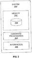
- FIG. 2 illustrates a block diagram of a system for estimating online scale for a monocular SLAM (simultaneous localization and mapping) based on multirotor dynamics in accordance with an embodiment of the present disclosure.
- the system 200 includes one or more processors 204, communication interface device(s) or input/output (I/O) interface(s) 206, and one or more data storage devices or memory 202 operatively coupled to the one or more processors 204.
- the memory 202 comprises a database 208.
- the one or more processors 204 that are hardware processors can be implemented as one or more microprocessors, microcomputers, microcontrollers, digital signal processors, central processing units, state machines, logic circuitries, and/or any devices that manipulate signals based on operational instructions.
- the processor(s) is configured to fetch and execute computer-readable instructions stored in the memory.
- the system 200 can be implemented in a variety of computing systems, such as laptop computers, notebooks, hand-held devices, workstations, mainframe computers, servers, a network cloud and the like.
- the I/O interface device(s) 206 can include a variety of software and hardware interfaces, for example, a web interface, a graphical user interface, and the like and can facilitate multiple communications within a wide variety of networks N/W and protocol types, including wired networks, for example, LAN, cable, etc., and wireless networks, such as WLAN, cellular, or satellite.
- the I/O interface device(s) can include one or more ports for connecting a number of devices to one another or to another server.
- the memory 202 may include any computer-readable medium known in the art including, for example, volatile memory, such as static random access memory (SRAM) and dynamic random access memory (DRAM), and/or non-volatile memory, such as read only memory (ROM), erasable programmable ROM, flash memories, hard disks, optical disks, and magnetic tapes.
- volatile memory such as static random access memory (SRAM) and dynamic random access memory (DRAM)
- DRAM dynamic random access memory
- non-volatile memory such as read only memory (ROM), erasable programmable ROM, flash memories, hard disks, optical disks, and magnetic tapes.
- the database 208 may store information but are not limited to, a plurality of parameters obtained from one or more sensors, wherein the parameters are specific to an entity (e.g., user, machine, and the like). Parameters may comprise sensor data captured through the sensors either connected to the user and/or machine. Further, the database 208 stores information pertaining to inputs fed to the system 200 and/or outputs generated by the system (e.g., at each stage), specific to the methodology described herein. More specifically, the database 208 stores information being processed at each step of the proposed methodology.
- entity e.g., user, machine, and the like
- Parameters may comprise sensor data captured through the sensors either connected to the user and/or machine.
- the database 208 stores information pertaining to inputs fed to the system 200 and/or outputs generated by the system (e.g., at each stage), specific to the methodology described herein. More specifically, the database 208 stores information being processed at each step of the proposed methodology.
- FIG. 3 illustrates an exemplary block diagram of a multirotor system 300 for estimating scale for a monocular SLAM based on the multirotor dynamics in accordance with an embodiment of the present disclosure.
- the multirotor system 300 includes a monocular camera 302, a camera pose 304, and an extended Kalman filter framework 306.
- the monocular camera 302 e.g., VO/ V- SLAM
- the monocular camera 302 is configured to estimate an arbitrary scaled position of a multirotor based on a vision SLAM (simultaneous localization and mapping) algorithm but not limited to visual odometry in a inertial frame.
- the Multirotor dynamics based online scale estimation for monocular SLAM computes the drag parameters online in the extended Kalman filter framework (EKF) 306 through vision. As a result, the scale computation now becomes an online process. Further, a theoretical proof for the observability of monocular camera scale is also presented. In an embodiment, the scale observability analysis is presented which shows that the scale of monocular camera becomes observable when multirotor dynamics model is employed, without relying on any other sensor such as an IMU. In an embodiment, the multirotor dynamics are used to define the model for scale estimation and observability analysis.
- EKF extended Kalman filter framework
- the extended Kalman filter framework 306 further includes a Multirotor dynamics based prediction module 306A and a Measurement update module 306B.
- the Multirotor dynamics based prediction module 306A is configured to receive an Euler angle estimated from the vision SLAM (simultaneous localization and mapping) algorithm (or technique) to compute an acceleration of the multirotor (or multirotor system).
- the multirotor or multirotor system
- the kinematic and kinetic equations are:
- Equation (5) the summation of rotor's angular velocity is often assumed constant for near hover condition.
- Equation (8) requires that vehicle's parameters ⁇ and m q should either be known apriori or computed online. Although m q is known, ⁇ is computed online using monocular camera in an EKF framework.
- the Equation (8) can now be integrated twice to generate the multirotor's pose. Equation (2) and Equation (8) are used to define the system model for observability analysis.
- the computed acceleration is then rotated to inertial frame, and followed by simple integration (e.g., double integrating) over varying time T, to estimate a metric velocity and a metric position of multirotor in the inertial frame.
- system model includes a propagation model and a measurement model.
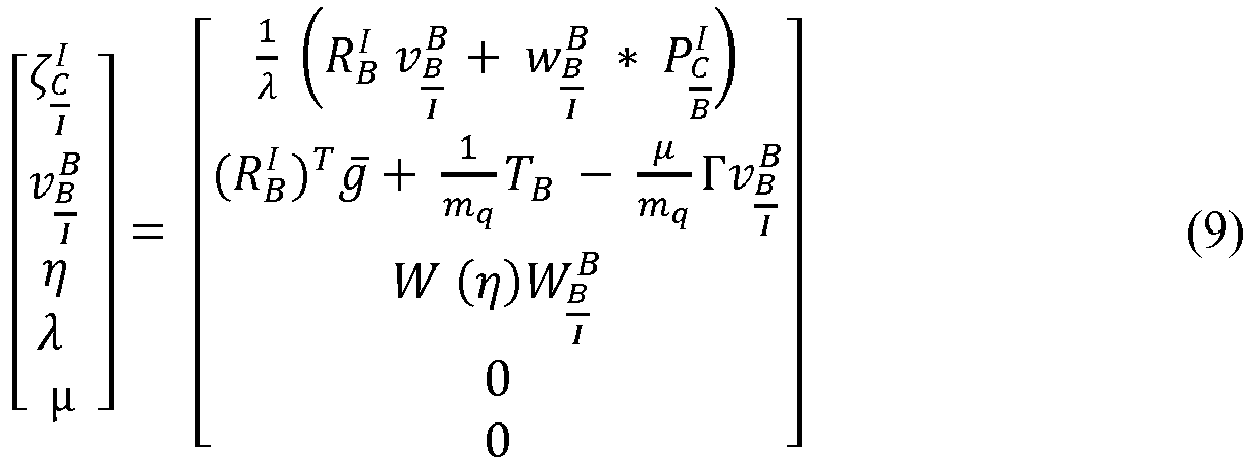
- Equation (9) The complete process model for vehicle's position and attitude subsystem is described in Equation (9).
- the measurement updating module 306B is configured to compare the estimated metric position with the estimated arbitrary position from the vision SLAM algorithm.
- the Extended Kalman filter framework 306 through which scale factor ⁇ , and drag coefficient ⁇ are determined online.
- the Multirotor dynamics based prediction module 306A as:
- ⁇ ⁇ R 3*1 is the arbitrary scaled position of the IMU/Camera in the inertial frame
- ⁇ v x b b v y b b v z b b T
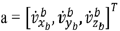
- a v ⁇ x b b v ⁇ y b b v ⁇ z b b T are the metric velocity and acceleration of the IMU/Camera in body frame respectively.
- the Measurement updating module 306B is configured to update measurement.
- R is the noise covariance matrix for the vision position, x M .
- the scale factor and the multirotor dynamics model parameters online are then used to estimate the scale factor and the multirotor dynamics model parameters online.
- the scale factor and a parameter associated with the multirotor dynamics model is estimated.
- parameter associated with the multirotor dynamics model is a drag coefficient.
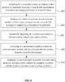
- FIG. 4 illustrates an exemplary flow diagram illustrating a method of estimating scale based on multirotor dynamics model of the multirotor system of FIG. 3 according to an embodiment of the present disclosure.
- the system 200 comprises one or more data storage devices or the memory 202 operatively coupled to the one or more hardware processors 204 and is configured to store instructions for execution of steps of the method by the one or more processors 204.
- the flow diagram depicted in FIG. 2 is better understood by way of following explanation/description.
- the one or more hardware processors 204 estimate, by a monocular camera (302), an arbitrary scaled position of a multirotor based on a vision SLAM ( simultaneous localization and mapping ) technique in an inertial frame.
- the one or more hardware processors 204 input, to a multirotor dynamics based prediction module (306A), an Euler angle estimated from the vision SLAM technique to compute an acceleration of the multirotor.
- the one or more hardware processors 204 dynamically integrate, the computed acceleration to estimate a metric velocity and a metric position.
- the one or more hardware processors 204 compare, in a measurement updating module (306B), the estimated metric position with the estimated arbitrary position from the vision SLAM technique.
- the one or more hardware processors 204 estimate, a scale factor and a parameter associated with a multirotor dynamics model.
- the parameters associated with the multirotor dynamics model is a drag coefficient.
- the scale factor is estimated based on a resultant error occurred during comparison between the estimated metric position with the estimated arbitrary position.
- the estimated arbitrary scaled position differs from the estimated metric position by the scale factor.
- the multirotor platform employed for hardware testing is an AR. Drone quadrotor.
- HD 720p - 30fps
- true value of vehicle's pose, position and orientation are required. These are obtained through an optitrack system, which consists of 8 motion capture cameras and provides pose data with accuracy on the order of a millimeter. The velocity and acceleration truth are obtained by sequentially differentiating the position data.
- the online scale estimation approach has been tested on two different data sets. One is locally produced datasets in our lab and another is Euroc MAV dataset Vicon Room 101. The vehicle was run in a planar lemniscate trajectory for the datasets obtained in our lab.
- the ORB SLAM algorithm/technique was used to produce arbitrarily scaled poses and to the scale orientation from camera feed for all datasets.
- the scale estimation results from the proposed approach on the local dataset i.e. FIG. 6 compares the obtained scale estimate with its true value, computed using the optitrack cameras. Also, the scale estimation method presented is implemented here for better comparison.
- FIG. 5A compares the estimated scale with its true value.
- the metric pose can now be generated.
- Table 1 Scale convergence time ( ⁇ 10%) 16 s RMS error in scale after convergence 0.09
- This approach provides a method to estimate the scale online solely for monocular SLAM by using the multirotor dynamics model in an extended Kalman Filter framework.
- An interesting approach postulates that scale information can be obtained solely, without any other sensor, from a monocular camera by exploiting the multirotor dynamics model.
- This approach produces scale estimate solely from monocular camera as long as the Euler angles of multirotor system are known from video feedback.
- This embodiments of present disclosure herein addresses unresolved problem of scale ambiguity in monocular SLAM in an online manner.
- the embodiments of the present disclosure thus facilitate the use of monocular SLAM to produce scaled metric poses without any prior processing such as IMU bias estimation, employed in other state of the art approaches.
- This approach provides the multirotor dynamics model which can be used to estimate the scale factor (online) through an EKF framework by using the vision sensor only.
- the effectiveness of the method of the present disclosure was judged based on performance on different datasets.
- the proposed algorithm/technique estimated the scale factor to be within ⁇ 10% of true value as shown in table 1. Thereby, the method works effectively for online scale estimation.
- the hardware device can be any kind of device which can be programmed including e.g. any kind of computer like a server or a personal computer, or the like, or any combination thereof.
- the device may also include means which could be e.g. hardware means like e.g. an application-specific integrated circuit (ASIC), a field-programmable gate array (FPGA), or a combination of hardware and software means, e.g.
- ASIC application-specific integrated circuit
- FPGA field-programmable gate array
- the means can include both hardware means and software means.
- the method embodiments described herein could be implemented in hardware and software.
- the device may also include software means.
- the embodiments may be implemented on different hardware devices, e.g. using a plurality of CPUs.
- the embodiments herein can comprise hardware and software elements.
- the embodiments that are implemented in software include but are not limited to, firmware, resident software, microcode, etc.
- the functions performed by various components described herein may be implemented in other components or combinations of other components.
- a computer-usable or computer readable medium can be any apparatus that can comprise, store, communicate, propagate, or transport the program for use by or in connection with the instruction execution system, apparatus, or device.
- a computer-readable storage medium refers to any type of physical memory on which information or data readable by a processor may be stored.
- a computer-readable storage medium may store instructions for execution by one or more processors, including instructions for causing the processor(s) to perform steps or stages consistent with the embodiments described herein.
- the term "computer-readable medium” should be understood to include tangible items and exclude carrier waves and transient signals, i.e., be non-transitory. Examples include random access memory (RAM), read-only memory (ROM), volatile memory, nonvolatile memory, hard drives, CD ROMs, DVDs, flash drives, disks, and any other known physical storage media.
Landscapes
- Engineering & Computer Science (AREA)
- Physics & Mathematics (AREA)
- General Physics & Mathematics (AREA)
- Radar, Positioning & Navigation (AREA)
- Remote Sensing (AREA)
- Computer Vision & Pattern Recognition (AREA)
- Theoretical Computer Science (AREA)
- Multimedia (AREA)
- Electromagnetism (AREA)
- Automation & Control Theory (AREA)
- Image Analysis (AREA)
Abstract
Description
- The present application claims priority from Indian patent application no.
201821035845, filed on September 24, 2018 - The disclosure herein generally relates to multirotors system, and, more particularly, to a system and method for estimating online scale for monocular vision based on multirotor dynamics.
- In advent of autonomous unmanned aerial vehicle (UAV) such as multirotors has had a strong impact in the robotics field. They have opened new avenues of research and are rapidly being deployed in search and exploration situations which were not accessible through UGVs. Tasks such as constructing 3D structures have now been accomplished through autonomous multirotors. There are lot of commercially available multirotors available in the market, which provide a video feedback using monocular camera. Researchers can easily use structure from motion concepts, to generate a reliable dense structure from this videos. But, the metric scale is absent within this estimation procedure. However, autonomous control requires accurate and frequent estimate of system states such as position and orientation. A number of research works have utilized external motion capture systems, but scaling them outside lab conditions is out of scope. State estimates can be obtained through GPS but the frequency is low and the error covariance is high. Also, they often fail in an indoor environment due to signal interference.
- Another widely used method is robotic vision based framework wherein an on-board camera device such as a monocular camera or stereo camera is used for state estimation through algorithms such as SLAM, VO. Stereo camera provide accurate state estimates up to scale but incurs a weight penalty. On the other hand monocular camera, while being a low cost and low weight solution, are scale agnostic i.e. they are scaled by an arbitrary factor. With reference to
FIG. 1 , in order to provide scale information, researchers have fused IMU or altitude sensor data, in metric scale, with the monocular vision sensor. The method for scale estimation in case of a monocular camera is using a metric sensor such as an IMU, Ultrasound beside others. Unlike conventional scale estimation methods that require input from one or more sensors such as an IMU or altitude sensor. - Embodiments of the present disclosure present technological improvements as solutions to one or more of the above-mentioned technical problems recognized by the inventors in conventional systems. For example, in one aspect, a processor implemented method of estimating online scale for a monocular SLAM is provided. The method comprises estimating, by a monocular camera, an arbitrary scaled position of a multirotor based on a vision SLAM (simultaneous localization and mapping) technique in an inertial frame; inputting, to a multirotor dynamics based prediction module, an Euler angle estimated from the vision SLAM technique to compute an acceleration of the multirotor; dynamically integrating, the computed acceleration to estimate a metric velocity and a metric position; comparing, in a measurement updating module, the estimated metric position with the estimated arbitrary position from the vision SLAM technique; and estimating, a scale factor and a parameter associated with a multirotor dynamics model, wherein the parameter associated with the multirotor dynamics model is a drag coefficient.
- In an embodiment, the scale factor may be estimated based on a resultant error occurred during comparison between the estimated metric position with the estimated arbitrary position. The estimated arbitrary scaled position may differ from the estimated metric position by the scale factor.
- In another aspect, there is provided a processor implemented system to estimate online scale for a monocular SLAM is provided. The system comprises: a memory storing instructions; one or more communication interfaces; and one or more hardware processors coupled to the memory via the one or more communication interfaces, wherein the one or more hardware processors are configured by the instructions to: estimate, by a monocular camera, an arbitrary scaled position of a multirotor based on a vision SLAM (simultaneous localization and mapping) technique in an inertial frame; input, to a multirotor dynamics based prediction module, an Euler angle estimated from the vision SLAM technique to compute an acceleration of the multirotor; dynamically integrate, the computed acceleration to estimate a metric velocity and a metric position; compare, in a measurement updating module, the estimated metric position with the estimated arbitrary position from the vision SLAM technique; and estimate, a scale factor and a parameter associated with a multirotor dynamics model, wherein the parameter associated with the multirotor dynamics model is a drag coefficient.
- In an embodiment, the scale factor may be estimated based on a resultant error occurred during comparison between the estimated metric position with the estimated arbitrary position. The estimated arbitrary scaled position may differ from the estimated metric position by the scale factor.
- In yet another aspect, there are provided one or more non-transitory machine readable information storage mediums comprising one or more instructions which when executed by one or more hardware processors causes estimating, by a monocular camera, an arbitrary scaled position of a multirotor based on a vision SLAM (simultaneous localization and mapping) technique in an inertial frame; inputting, to a multirotor dynamics based prediction module, an Euler angle estimated from the vision SLAM technique to compute an acceleration of the multirotor; dynamically integrating, the computed acceleration to estimate a metric velocity and a metric position; comparing, in a measurement updating module, the estimated metric position with the estimated arbitrary position from the vision SLAM technique; and estimating, a scale factor and a parameter associated with a multirotor dynamics model, wherein the parameter associated with the multirotor dynamics model is a drag coefficient.
- In an embodiment, the scale factor may be estimated based on a resultant error occurred during comparison between the estimated metric position with the estimated arbitrary position. The estimated arbitrary scaled position may differ from the estimated metric position by the scale factor.
- It is to be understood that both the foregoing general description and the following detailed description are exemplary and explanatory only and are not restrictive of the invention, as claimed.
- The accompanying drawings, which are incorporated in and constitute a part of this disclosure, illustrate exemplary embodiments and, together with the description, serve to explain the disclosed principles:
-
FIG. 1 illustrates a typical approach of fusing vision sensor and IMU sensor in Fusion framework for scale estimation. -
FIG. 2 illustrates a block diagram of a system for estimating online scale for a monocular SLAM (simultaneous localization and mapping) based on multirotor dynamics in accordance with an embodiment of the present disclosure. -
FIG. 3 illustrates an exemplary block diagram of a multirotor system for estimating online scale for a monocular SLAM based on a multirotor dynamics in accordance with an embodiment of the present disclosure. -
FIG. 4 illustrates an exemplary flow diagram illustrating a method of estimating online scale for a monocular SLAM based on multirotor dynamics of the multirotor system ofFIG. 3 according to an embodiment of the present disclosure. -
FIG. 5A-5C illustrates an exemplary graphical representation of online scale estimation in accordance with an exemplary embodiment of the present disclosure. - Exemplary embodiments are described with reference to the accompanying drawings. In the figures, the left-most digit(s) of a reference number identifies the figure in which the reference number first appears. Wherever convenient, the same reference numbers are used throughout the drawings to refer to the same or like parts. While examples and features of disclosed principles are described herein, modifications, adaptations, and other implementations are possible without departing from the scope of the disclosed embodiments. It is intended that the following detailed description be considered as exemplary only, with the true scope being indicated by the following claims.
- Referring now to the drawings, and more particularly to
FIGS. 1 through FIG. 5C , where similar reference characters denote corresponding features consistently throughout the figures, there are shown preferred embodiments and these embodiments are described in the context of the following exemplary system and/or method. -
FIG. 2 illustrates a block diagram of a system for estimating online scale for a monocular SLAM (simultaneous localization and mapping) based on multirotor dynamics in accordance with an embodiment of the present disclosure. In an embodiment, thesystem 200 includes one ormore processors 204, communication interface device(s) or input/output (I/O) interface(s) 206, and one or more data storage devices ormemory 202 operatively coupled to the one ormore processors 204. Thememory 202 comprises adatabase 208. The one ormore processors 204 that are hardware processors can be implemented as one or more microprocessors, microcomputers, microcontrollers, digital signal processors, central processing units, state machines, logic circuitries, and/or any devices that manipulate signals based on operational instructions. Among other capabilities, the processor(s) is configured to fetch and execute computer-readable instructions stored in the memory. In an embodiment, thesystem 200 can be implemented in a variety of computing systems, such as laptop computers, notebooks, hand-held devices, workstations, mainframe computers, servers, a network cloud and the like. - The I/O interface device(s) 206 can include a variety of software and hardware interfaces, for example, a web interface, a graphical user interface, and the like and can facilitate multiple communications within a wide variety of networks N/W and protocol types, including wired networks, for example, LAN, cable, etc., and wireless networks, such as WLAN, cellular, or satellite. In an embodiment, the I/O interface device(s) can include one or more ports for connecting a number of devices to one another or to another server.
- The
memory 202 may include any computer-readable medium known in the art including, for example, volatile memory, such as static random access memory (SRAM) and dynamic random access memory (DRAM), and/or non-volatile memory, such as read only memory (ROM), erasable programmable ROM, flash memories, hard disks, optical disks, and magnetic tapes. - The
database 208 may store information but are not limited to, a plurality of parameters obtained from one or more sensors, wherein the parameters are specific to an entity (e.g., user, machine, and the like). Parameters may comprise sensor data captured through the sensors either connected to the user and/or machine. Further, thedatabase 208 stores information pertaining to inputs fed to thesystem 200 and/or outputs generated by the system (e.g., at each stage), specific to the methodology described herein. More specifically, thedatabase 208 stores information being processed at each step of the proposed methodology. -
FIG. 3 illustrates an exemplary block diagram of a multirotor system 300 for estimating scale for a monocular SLAM based on the multirotor dynamics in accordance with an embodiment of the present disclosure. The multirotor system 300 includes amonocular camera 302, acamera pose 304, and an extendedKalman filter framework 306. The monocular camera 302 (e.g., VO/ V- SLAM) is configured to estimate an arbitrary scaled position of a multirotor based on a vision SLAM (simultaneous localization and mapping) algorithm but not limited to visual odometry in a inertial frame. - The Multirotor dynamics based online scale estimation for monocular SLAM. In an embodiment, this approach computes the drag parameters online in the extended Kalman filter framework (EKF) 306 through vision. As a result, the scale computation now becomes an online process. Further, a theoretical proof for the observability of monocular camera scale is also presented. In an embodiment, the scale observability analysis is presented which shows that the scale of monocular camera becomes observable when multirotor dynamics model is employed, without relying on any other sensor such as an IMU. In an embodiment, the multirotor dynamics are used to define the model for scale estimation and observability analysis.
- The extended
Kalman filter framework 306 further includes a Multirotor dynamics basedprediction module 306A and a Measurement update module 306B. The Multirotor dynamics basedprediction module 306A is configured to receive an Euler angle estimated from the vision SLAM (simultaneous localization and mapping) algorithm (or technique) to compute an acceleration of the multirotor (or multirotor system). For example, the multirotor (or multirotor system) is a rigid body and thus Newton-Euler equations can be used to describe dynamics. The kinematic and kinetic equations are: - For example, arbitrary scaled camera pose differs from the metric pose by a scale factor λ.


- Differentiating Equation (1) yields,

- Also, time rate of evolution of η can be expressed as,


- In the body frame, the force required for the acceleration of mass,


- Here Pi is angular velocity of ith rotor, k is a constant, and

- Although the drag force is dependent on rotor's angular velocity, given by Equation (5), the summation of rotor's angular velocity is often assumed constant for near hover condition. Here, it is assumed that µx and µy represent the constant lumped drag parameters along body fixed x-y axis respectively such that,

- Further assuming that µx = µy = µ as assumed. As a result, FD can be written as,

- Ignoring the Coriolis forces in Eqn. 4, time evolution of


- For example, Equation (8) requires that vehicle's parameters µ and mq should either be known apriori or computed online. Although mq is known, µ is computed online using monocular camera in an EKF framework. The Equation (8) can now be integrated twice to generate the multirotor's pose. Equation (2) and Equation (8) are used to define the system model for observability analysis. The computed acceleration is then rotated to inertial frame, and followed by simple integration (e.g., double integrating) over varying time T, to estimate a metric velocity and a metric position of multirotor in the inertial frame.
- In one embodiment, system model includes a propagation model and a measurement model.
- The complete process model for vehicle's position and attitude subsystem is described in Equation (9). Here, system states are defined as

- Monocular VO/V-SLAM algorithm produces arbitrary scaled position,


- Vision sensor measures rotation,


- The measurement updating module 306B is configured to compare the estimated metric position with the estimated arbitrary position from the vision SLAM algorithm. In an embodiment, the Extended
Kalman filter framework 306 through which scale factor λ, and drag coefficient µ are determined online. - The Multirotor dynamics based
prediction module 306A as: - Example 1: Assuming visual SLAM provides accurate attitude estimation (η). Further, the scale (λ) and rotor drag (µ) are observable even when body angular velocities

- Example 2: Assuming that translation between camera frame and body frame is negligible compared to other translational motions.
- Example 3: As in Equation (8),


- Based on these assumptions, system state can be defined as,

- Where ζ ∈ R 3*1 is the arbitrary scaled position of the IMU/Camera in the inertial frame,



- Further, Jacobian of the model is given by,


- The Measurement updating module 306B is configured to update measurement. The measurement update is given as,



xM is the arbitrary scaled position obtained from the vision SLAM in the inertial frame. R is the noise covariance matrix for the vision position,xM . - An resulting error due to comparison between aforementioned poses is then used to estimate the scale factor and the multirotor dynamics model parameters online. In an embodiment, the scale factor and a parameter associated with the multirotor dynamics model is estimated. For example, parameter associated with the multirotor dynamics model is a drag coefficient.
-
FIG. 4 illustrates an exemplary flow diagram illustrating a method of estimating scale based on multirotor dynamics model of the multirotor system ofFIG. 3 according to an embodiment of the present disclosure. In an embodiment, thesystem 200 comprises one or more data storage devices or thememory 202 operatively coupled to the one ormore hardware processors 204 and is configured to store instructions for execution of steps of the method by the one ormore processors 204. The flow diagram depicted inFIG. 2 is better understood by way of following explanation/description. - The steps of the method of the present disclosure will now be explained with reference to the components of the
system 200 as depicted inFIG. 3 , and the flow diagram ofFIG. 2 . In an embodiment of the present disclosure, atstep 402, the one ormore hardware processors 204, estimate, by a monocular camera (302), an arbitrary scaled position of a multirotor based on a vision SLAM (simultaneous localization and mapping) technique in an inertial frame. In an embodiment of the present disclosure, atstep 404, the one ormore hardware processors 204 input, to a multirotor dynamics based prediction module (306A), an Euler angle estimated from the vision SLAM technique to compute an acceleration of the multirotor. In an embodiment of the present disclosure, atstep 406, the one ormore hardware processors 204 dynamically integrate, the computed acceleration to estimate a metric velocity and a metric position. - In an embodiment of the present disclosure, at
step 408, the one ormore hardware processors 204, compare, in a measurement updating module (306B), the estimated metric position with the estimated arbitrary position from the vision SLAM technique. In an embodiment of the present disclosure, atstep 410, the one ormore hardware processors 204 estimate, a scale factor and a parameter associated with a multirotor dynamics model. In an embodiment, the parameters associated with the multirotor dynamics model is a drag coefficient. In an embodiment, the scale factor is estimated based on a resultant error occurred during comparison between the estimated metric position with the estimated arbitrary position. In an embodiment, the estimated arbitrary scaled position differs from the estimated metric position by the scale factor. - In an exemplary embodiment, the multirotor platform employed for hardware testing is an AR. Drone quadrotor. For example, HD (720p - 30fps) front facing camera feed can be accessed through its driver node. In order to validate the obtained results, true value of vehicle's pose, position and orientation, are required. These are obtained through an optitrack system, which consists of 8 motion capture cameras and provides pose data with accuracy on the order of a millimeter. The velocity and acceleration truth are obtained by sequentially differentiating the position data. The online scale estimation approach has been tested on two different data sets. One is locally produced datasets in our lab and another is Euroc MAV dataset Vicon Room 101. The vehicle was run in a planar lemniscate trajectory for the datasets obtained in our lab. The ORB SLAM algorithm/technique was used to produce arbitrarily scaled poses and to the scale orientation from camera feed for all datasets.
- The results obtained on different datasets for online scale estimation using multirotor dynamics.
- In another exemplary embodiment, the scale estimation results from the proposed approach on the local dataset i.e. FIG. 6 compares the obtained scale estimate with its true value, computed using the optitrack cameras. Also, the scale estimation method presented is implemented here for better comparison.
- In an exemplary embodiment, implementing the proposed method on the standard Euroc Vicon Room 101 dataset.
FIG. 5A compares the estimated scale with its true value. As a result of the scale estimation, the metric pose can now be generated.Table 1 Scale convergence time (±10%) 16 s RMS error in scale after convergence 0.09 RMS error: Y Pose 0.3952 m RMS error: X Pose 0.2949 m - TABLE 1: The estimated value of scale converges to within ± 10% of its true value in about 16 seconds. Table 1 quantifies the proposed method in terms of the RMS error and convergence time obtained on the standard dataset.
- This approach provides a method to estimate the scale online solely for monocular SLAM by using the multirotor dynamics model in an extended Kalman Filter framework. An interesting approach postulates that scale information can be obtained solely, without any other sensor, from a monocular camera by exploiting the multirotor dynamics model. This approach produces scale estimate solely from monocular camera as long as the Euler angles of multirotor system are known from video feedback.
- This is a clear advancement over scale estimation methods which requires information from some other sensors or knowledge of physical dimension of an object within the camera view. Here, utilizes the theory behind multirotor dynamics model and estimates the scale factor online in an EKF framework. Simultaneously, the drag parameters pertaining to the dynamics model is also obtained which facilitates better estimation of scale. Further, the observability of scale and theoretically show that the scale becomes observable when multirotor dynamics model and monocular vision are used in conjunction.
- This embodiments of present disclosure herein addresses unresolved problem of scale ambiguity in monocular SLAM in an online manner. The embodiments of the present disclosure, thus facilitate the use of monocular SLAM to produce scaled metric poses without any prior processing such as IMU bias estimation, employed in other state of the art approaches. This approach provides the multirotor dynamics model which can be used to estimate the scale factor (online) through an EKF framework by using the vision sensor only. The effectiveness of the method of the present disclosure was judged based on performance on different datasets. The proposed algorithm/technique estimated the scale factor to be within ±10% of true value as shown in table 1. Thereby, the method works effectively for online scale estimation.
- The written description describes the subject matter herein to enable any person skilled in the art to make and use the embodiments. The scope of the subject matter embodiments is defined by the claims and may include other modifications that occur to those skilled in the art. Such other modifications are intended to be within the scope of the claims if they have similar elements that do not differ from the literal language of the claims or if they include equivalent elements with insubstantial differences from the literal language of the claims.
- It is to be understood that the scope of the protection is extended to such a program and in addition to a computer-readable means having a message therein; such computer-readable storage means contain program-code means for implementation of one or more steps of the method, when the program runs on a server or mobile device or any suitable programmable device. The hardware device can be any kind of device which can be programmed including e.g. any kind of computer like a server or a personal computer, or the like, or any combination thereof. The device may also include means which could be e.g. hardware means like e.g. an application-specific integrated circuit (ASIC), a field-programmable gate array (FPGA), or a combination of hardware and software means, e.g. an ASIC and an FPGA, or at least one microprocessor and at least one memory with software processing components located therein. Thus, the means can include both hardware means and software means. The method embodiments described herein could be implemented in hardware and software. The device may also include software means. Alternatively, the embodiments may be implemented on different hardware devices, e.g. using a plurality of CPUs.
- The embodiments herein can comprise hardware and software elements. The embodiments that are implemented in software include but are not limited to, firmware, resident software, microcode, etc. The functions performed by various components described herein may be implemented in other components or combinations of other components. For the purposes of this description, a computer-usable or computer readable medium can be any apparatus that can comprise, store, communicate, propagate, or transport the program for use by or in connection with the instruction execution system, apparatus, or device.
- The illustrated steps are set out to explain the exemplary embodiments shown, and it should be anticipated that ongoing technological development will change the manner in which particular functions are performed. These examples are presented herein for purposes of illustration, and not limitation. Further, the boundaries of the functional building blocks have been arbitrarily defined herein for the convenience of the description. Alternative boundaries can be defined so long as the specified functions and relationships thereof are appropriately performed. Alternatives (including equivalents, extensions, variations, deviations, etc., of those described herein) will be apparent to persons skilled in the relevant art(s) based on the teachings contained herein. Such alternatives fall within the scope of the disclosed embodiments. Also, the words "comprising," "having," "containing," and "including," and other similar forms are intended to be equivalent in meaning and be open ended in that an item or items following any one of these words is not meant to be an exhaustive listing of such item or items, or meant to be limited to only the listed item or items. It must also be noted that as used herein and in the appended claims, the singular forms "a," "an," and "the" include plural references unless the context clearly dictates otherwise.
- Furthermore, one or more computer-readable storage media may be utilized in implementing embodiments consistent with the present disclosure. A computer-readable storage medium refers to any type of physical memory on which information or data readable by a processor may be stored. Thus, a computer-readable storage medium may store instructions for execution by one or more processors, including instructions for causing the processor(s) to perform steps or stages consistent with the embodiments described herein. The term "computer-readable medium" should be understood to include tangible items and exclude carrier waves and transient signals, i.e., be non-transitory. Examples include random access memory (RAM), read-only memory (ROM), volatile memory, nonvolatile memory, hard drives, CD ROMs, DVDs, flash drives, disks, and any other known physical storage media.
- It is intended that the disclosure and examples be considered as exemplary only, with a true scope of disclosed embodiments being indicated by the following claims.
Claims (6)
- A processor-implemented method of estimating online scale for a monocular SLAM, comprising:(a) estimating, by a monocular camera (302), an arbitrary scaled position of a multirotor based on a vision SLAM (simultaneous localization and mapping) technique in an inertial frame;(b) inputting, to a multirotor dynamics based prediction module (306A), an Euler angle estimated from the vision SLAM technique to compute an acceleration of the multirotor;(c) dynamically integrating, the computed acceleration to estimate a metric velocity and a metric position;(d) comparing, in a measurement updating module (306B), the estimated metric position with the estimated arbitrary position from the vision SLAM technique; and(e) estimating, a scale factor and a parameter associated with a multirotor dynamics model, wherein the parameter associated with the multirotor dynamics model is a drag coefficient.
- The processor implemented method of claim 1, wherein the scale factor is estimated based on a resultant error occurred during comparison between the estimated metric position with the estimated arbitrary position.
- The processor implemented method of claim 1, wherein the estimated arbitrary scaled position differs from the estimated metric position by the scale factor.
- A multirotor system (300) comprising:a memory (202) storing instructions;one or more communication interfaces (206); andone or more hardware processors (204) coupled to the memory (202) via the one or more communication interfaces (206), wherein the one or more hardware processors (204) are configured by the instructions to:(a) estimate, by a monocular camera (302), an arbitrary scaled position of a multirotor based on a vision SLAM (simultaneous localization and mapping) technique in an inertial frame;(b) input, to a multirotor dynamics based prediction module (306A), an Euler angle estimated from the vision SLAM technique to compute an acceleration of the multirotor;(c) dynamically integrate, the computed acceleration to estimate a metric velocity and a metric position;(d) compare, in a measurement updating module (306B), the estimated metric position with the estimated arbitrary position from the vision SLAM technique; and(e) estimate, a scale factor and a parameter associated with a multirotor dynamics model, wherein the parameter associated with the multirotor dynamics model is a drag coefficient.
- The multirotor system (300) of claim 4, wherein the scale factor is estimated based on a resultant error occurred during comparison between the estimated metric position with the estimated arbitrary position.
- The multirotor system (300) of claim 4, wherein the estimated arbitrary scaled position differs from the estimated metric position by the scale factor.
Applications Claiming Priority (1)
| Application Number | Priority Date | Filing Date | Title |
|---|---|---|---|
| IN201821035845 | 2018-09-24 |
Publications (2)
| Publication Number | Publication Date |
|---|---|
| EP3627447A1 true EP3627447A1 (en) | 2020-03-25 |
| EP3627447B1 EP3627447B1 (en) | 2022-06-29 |
Family
ID=68051682
Family Applications (1)
| Application Number | Title | Priority Date | Filing Date |
|---|---|---|---|
| EP19198914.4A Active EP3627447B1 (en) | 2018-09-24 | 2019-09-23 | System and method of multirotor dynamics based online scale estimation for monocular vision |
Country Status (2)
| Country | Link |
|---|---|
| US (1) | US10748299B2 (en) |
| EP (1) | EP3627447B1 (en) |
Cited By (3)
| Publication number | Priority date | Publication date | Assignee | Title |
|---|---|---|---|---|
| CN111604598A (en) * | 2020-05-06 | 2020-09-01 | 大连理工大学 | A tool setting method for a robotic arm feeding laser etching system |
| CN111784775A (en) * | 2020-07-13 | 2020-10-16 | 中国人民解放军军事科学院国防科技创新研究院 | Identification-assisted visual inertia augmented reality registration method |
| CN116090224A (en) * | 2023-01-12 | 2023-05-09 | 北京理工大学 | Unmanned system external force and external force moment online estimation method based on error state Kalman filtering |
Families Citing this family (1)
| Publication number | Priority date | Publication date | Assignee | Title |
|---|---|---|---|---|
| CN113503873B (en) * | 2021-07-14 | 2024-03-12 | 北京理工大学 | A multi-sensor fusion visual positioning method |
Citations (1)
| Publication number | Priority date | Publication date | Assignee | Title |
|---|---|---|---|---|
| US20150219767A1 (en) * | 2014-02-03 | 2015-08-06 | Board Of Regents, The University Of Texas System | System and method for using global navigation satellite system (gnss) navigation and visual navigation to recover absolute position and attitude without any prior association of visual features with known coordinates |
Family Cites Families (15)
| Publication number | Priority date | Publication date | Assignee | Title |
|---|---|---|---|---|
| US9031782B1 (en) * | 2012-01-23 | 2015-05-12 | The United States Of America As Represented By The Secretary Of The Navy | System to use digital cameras and other sensors in navigation |
| WO2014018147A2 (en) * | 2012-04-30 | 2014-01-30 | The Trustees Of The University Of Pennsylvania | Three-dimensional manipulation of teams of quadrotors |
| FR3000813B1 (en) * | 2013-01-04 | 2016-04-15 | Parrot | ROTARY SAILING DRONE COMPRISING MEANS FOR AUTONOMOUS POSITION DETERMINATION IN AN ABSOLUTE FLOOR - RELATED MARK. |
| JP6285543B2 (en) * | 2013-06-09 | 2018-02-28 | アイトゲネシシェ・テヒニシェ・ホーホシューレ・チューリヒ | Controlled flight of multicopters subject to faults affecting effectors |
| WO2015105597A2 (en) * | 2013-11-27 | 2015-07-16 | The Trustees Of The University Of Pennsylvania | Multi-sensor fusion for robust autonomous flight in indoor and outdoor environments with a rotorcraft micro-aerial vehicle (mav) |
| CN104062977B (en) | 2014-06-17 | 2017-04-19 | 天津大学 | Full-autonomous flight control method for quadrotor unmanned aerial vehicle based on vision SLAM |
| US9969492B2 (en) * | 2015-09-04 | 2018-05-15 | Nutech Ventures | Crop height estimation with unmanned aerial vehicles |
| US10665115B2 (en) * | 2016-01-05 | 2020-05-26 | California Institute Of Technology | Controlling unmanned aerial vehicles to avoid obstacle collision |
| US10578457B2 (en) * | 2016-09-15 | 2020-03-03 | Syracuse University | Robust and stable autonomous vision-inertial navigation system for unmanned vehicles |
| US10464670B2 (en) * | 2017-02-22 | 2019-11-05 | Gopro, Inc. | Variable condition motor controller |
| CN206804018U (en) | 2017-04-13 | 2017-12-26 | 高域(北京)智能科技研究院有限公司 | Environmental data server, unmanned vehicle and alignment system |
| CA2986526C (en) * | 2017-07-31 | 2023-10-17 | Queen's University At Kingston | Autorotating unmanned aerial vehicle surveying platform |
| WO2019051832A1 (en) * | 2017-09-18 | 2019-03-21 | 深圳市大疆创新科技有限公司 | Movable object control method, device and system |
| US10657833B2 (en) * | 2017-11-30 | 2020-05-19 | Intel Corporation | Vision-based cooperative collision avoidance |
| US11277956B2 (en) * | 2018-07-26 | 2022-03-22 | Bear Flag Robotics, Inc. | Vehicle controllers for agricultural and industrial applications |
-
2019
- 2019-09-23 EP EP19198914.4A patent/EP3627447B1/en active Active
- 2019-09-24 US US16/580,403 patent/US10748299B2/en active Active
Patent Citations (1)
| Publication number | Priority date | Publication date | Assignee | Title |
|---|---|---|---|---|
| US20150219767A1 (en) * | 2014-02-03 | 2015-08-06 | Board Of Regents, The University Of Texas System | System and method for using global navigation satellite system (gnss) navigation and visual navigation to recover absolute position and attitude without any prior association of visual features with known coordinates |
Non-Patent Citations (4)
| Title |
|---|
| DINUKA ABEYWARDENA ET AL: "Fast, On-board, Model-aided Visual-Inertial Odometry System for Quadrotor Micro Aerial Vehicles", ARXIV.ORG, CORNELL UNIVERSITY LIBRARY, 201 OLIN LIBRARY CORNELL UNIVERSITY ITHACA, NY 14853, 6 July 2016 (2016-07-06), XP080712299, DOI: 10.1109/ICRA.2016.7487290 * |
| LEISHMAN ROBERT C ET AL: "Quadrotors and Accelerometers: State Estimation with an Improved Dynamic Model", IEEE CONTROL SYSTEMS, IEEE, USA, vol. 34, no. 1, 1 February 2014 (2014-02-01), pages 28 - 41, XP011537212, ISSN: 1066-033X, [retrieved on 20140115], DOI: 10.1109/MCS.2013.2287362 * |
| MATTHIAS FAESSLER ET AL: "Autonomous, Vision-based Flight and Live Dense 3D Mapping with a Quadrotor Micro Aerial Vehicle", JOURNAL OF FIELD ROBOTICS, vol. 33, no. 4, 17 March 2015 (2015-03-17), US, pages 431 - 450, XP055629950, ISSN: 1556-4959, DOI: 10.1002/rob.21581 * |
| SPAENLEHAUER ARIANE ET AL: "A loosely-coupled approach for metric scale estimation in monocular vision-inertial systems", 2017 IEEE INTERNATIONAL CONFERENCE ON MULTISENSOR FUSION AND INTEGRATION FOR INTELLIGENT SYSTEMS (MFI), IEEE, 16 November 2017 (2017-11-16), pages 137 - 143, XP033264823, DOI: 10.1109/MFI.2017.8170419 * |
Cited By (5)
| Publication number | Priority date | Publication date | Assignee | Title |
|---|---|---|---|---|
| CN111604598A (en) * | 2020-05-06 | 2020-09-01 | 大连理工大学 | A tool setting method for a robotic arm feeding laser etching system |
| CN111604598B (en) * | 2020-05-06 | 2021-04-20 | 大连理工大学 | A tool setting method for a robotic arm feeding laser etching system |
| CN111784775A (en) * | 2020-07-13 | 2020-10-16 | 中国人民解放军军事科学院国防科技创新研究院 | Identification-assisted visual inertia augmented reality registration method |
| CN111784775B (en) * | 2020-07-13 | 2021-05-04 | 中国人民解放军军事科学院国防科技创新研究院 | Identification-assisted visual inertia augmented reality registration method |
| CN116090224A (en) * | 2023-01-12 | 2023-05-09 | 北京理工大学 | Unmanned system external force and external force moment online estimation method based on error state Kalman filtering |
Also Published As
| Publication number | Publication date |
|---|---|
| US10748299B2 (en) | 2020-08-18 |
| EP3627447B1 (en) | 2022-06-29 |
| US20200098129A1 (en) | 2020-03-26 |
Similar Documents
| Publication | Publication Date | Title |
|---|---|---|
| US20250130045A1 (en) | Square-Root Multi-State Constraint Kalman Filter for Vision-Aided Inertial Navigation System | |
| US10203209B2 (en) | Resource-aware large-scale cooperative 3D mapping using multiple mobile devices | |
| US9709404B2 (en) | Iterative Kalman Smoother for robust 3D localization for vision-aided inertial navigation | |
| US10371529B2 (en) | Computational budget estimation for vision-aided inertial navigation systems | |
| US9996941B2 (en) | Constrained key frame localization and mapping for vision-aided inertial navigation | |
| US9243916B2 (en) | Observability-constrained vision-aided inertial navigation | |
| US10748299B2 (en) | System and method of multirotor dynamics based online scale estimation for monocular vision | |
| US20190301871A1 (en) | Direct Sparse Visual-Inertial Odometry Using Dynamic Marginalization | |
| EP3470787A1 (en) | Multi-sensor fusion for robust autonomous flight in indoor and outdoor environments with a rotorcraft micro-aerial vehicle (mav) | |
| Indelman et al. | Incremental light bundle adjustment for robotics navigation | |
| DuToit et al. | Consistent map-based 3D localization on mobile devices | |
| Li et al. | Exploring the potential of the deep-learning-aided Kalman filter for GNSS/INS integration: A study on 2-D simulation datasets | |
| US12099375B2 (en) | Multiple target interception | |
| Zhou et al. | Learned monocular depth priors in visual-inertial initialization | |
| Nguyen et al. | VR-SLAM: A visual-range simultaneous localization and mapping system using monocular camera and ultra-wideband sensors | |
| Zhu et al. | Conservative uncertainty estimation in map-based vision-aided navigation | |
| US11525683B2 (en) | Drift-free velocity estimation for multirotor systems and localization thereof | |
| Sadeghzadeh-Nokhodberiz et al. | Vision-based particle filtering for quad-copter attitude estimation using multirate delayed measurements | |
| US11958194B2 (en) | Control command based adaptive system and method for estimating motion parameters of differential drive vehicles | |
| Rao et al. | Computationally light spectrally normalized memory neuron network based estimator for gps-denied operation of micro-uav | |
| Liu et al. | Semi-dense visual-inertial odometry and mapping for computationally constrained platforms | |
| Stepanyan et al. | Adaptive multi-sensor information fusion for autonomous urban air mobility operations | |
| Sakamaki et al. | Tracking multiple ground objects using a team of unmanned air vehicles | |
| Agunbiade | A review: Simultaneous localization and mapping algorithms | |
| Magree | Monocular vision-aided inertial navigation for unmanned aerial vehicles |
Legal Events
| Date | Code | Title | Description |
|---|---|---|---|
| PUAI | Public reference made under article 153(3) epc to a published international application that has entered the european phase |
Free format text: ORIGINAL CODE: 0009012 |
|
| STAA | Information on the status of an ep patent application or granted ep patent |
Free format text: STATUS: THE APPLICATION HAS BEEN PUBLISHED |
|
| AK | Designated contracting states |
Kind code of ref document: A1 Designated state(s): AL AT BE BG CH CY CZ DE DK EE ES FI FR GB GR HR HU IE IS IT LI LT LU LV MC MK MT NL NO PL PT RO RS SE SI SK SM TR |
|
| AX | Request for extension of the european patent |
Extension state: BA ME |
|
| STAA | Information on the status of an ep patent application or granted ep patent |
Free format text: STATUS: REQUEST FOR EXAMINATION WAS MADE |
|
| 17P | Request for examination filed |
Effective date: 20200925 |
|
| RBV | Designated contracting states (corrected) |
Designated state(s): AL AT BE BG CH CY CZ DE DK EE ES FI FR GB GR HR HU IE IS IT LI LT LU LV MC MK MT NL NO PL PT RO RS SE SI SK SM TR |
|
| GRAP | Despatch of communication of intention to grant a patent |
Free format text: ORIGINAL CODE: EPIDOSNIGR1 |
|
| STAA | Information on the status of an ep patent application or granted ep patent |
Free format text: STATUS: GRANT OF PATENT IS INTENDED |
|
| INTG | Intention to grant announced |
Effective date: 20220113 |
|
| GRAS | Grant fee paid |
Free format text: ORIGINAL CODE: EPIDOSNIGR3 |
|
| GRAA | (expected) grant |
Free format text: ORIGINAL CODE: 0009210 |
|
| STAA | Information on the status of an ep patent application or granted ep patent |
Free format text: STATUS: THE PATENT HAS BEEN GRANTED |
|
| AK | Designated contracting states |
Kind code of ref document: B1 Designated state(s): AL AT BE BG CH CY CZ DE DK EE ES FI FR GB GR HR HU IE IS IT LI LT LU LV MC MK MT NL NO PL PT RO RS SE SI SK SM TR |
|
| REG | Reference to a national code |
Ref country code: CH Ref legal event code: EP |
|
| REG | Reference to a national code |
Ref country code: AT Ref legal event code: REF Ref document number: 1501833 Country of ref document: AT Kind code of ref document: T Effective date: 20220715 |
|
| REG | Reference to a national code |
Ref country code: IE Ref legal event code: FG4D |
|
| REG | Reference to a national code |
Ref country code: DE Ref legal event code: R096 Ref document number: 602019016370 Country of ref document: DE |
|
| REG | Reference to a national code |
Ref country code: NL Ref legal event code: FP |
|
| REG | Reference to a national code |
Ref country code: LT Ref legal event code: MG9D |
|
| PG25 | Lapsed in a contracting state [announced via postgrant information from national office to epo] |
Ref country code: SE Free format text: LAPSE BECAUSE OF FAILURE TO SUBMIT A TRANSLATION OF THE DESCRIPTION OR TO PAY THE FEE WITHIN THE PRESCRIBED TIME-LIMIT Effective date: 20220629 Ref country code: NO Free format text: LAPSE BECAUSE OF FAILURE TO SUBMIT A TRANSLATION OF THE DESCRIPTION OR TO PAY THE FEE WITHIN THE PRESCRIBED TIME-LIMIT Effective date: 20220929 Ref country code: LT Free format text: LAPSE BECAUSE OF FAILURE TO SUBMIT A TRANSLATION OF THE DESCRIPTION OR TO PAY THE FEE WITHIN THE PRESCRIBED TIME-LIMIT Effective date: 20220629 Ref country code: HR Free format text: LAPSE BECAUSE OF FAILURE TO SUBMIT A TRANSLATION OF THE DESCRIPTION OR TO PAY THE FEE WITHIN THE PRESCRIBED TIME-LIMIT Effective date: 20220629 Ref country code: GR Free format text: LAPSE BECAUSE OF FAILURE TO SUBMIT A TRANSLATION OF THE DESCRIPTION OR TO PAY THE FEE WITHIN THE PRESCRIBED TIME-LIMIT Effective date: 20220930 Ref country code: FI Free format text: LAPSE BECAUSE OF FAILURE TO SUBMIT A TRANSLATION OF THE DESCRIPTION OR TO PAY THE FEE WITHIN THE PRESCRIBED TIME-LIMIT Effective date: 20220629 Ref country code: BG Free format text: LAPSE BECAUSE OF FAILURE TO SUBMIT A TRANSLATION OF THE DESCRIPTION OR TO PAY THE FEE WITHIN THE PRESCRIBED TIME-LIMIT Effective date: 20220929 |
|
| REG | Reference to a national code |
Ref country code: AT Ref legal event code: MK05 Ref document number: 1501833 Country of ref document: AT Kind code of ref document: T Effective date: 20220629 |
|
| PG25 | Lapsed in a contracting state [announced via postgrant information from national office to epo] |
Ref country code: RS Free format text: LAPSE BECAUSE OF FAILURE TO SUBMIT A TRANSLATION OF THE DESCRIPTION OR TO PAY THE FEE WITHIN THE PRESCRIBED TIME-LIMIT Effective date: 20220629 Ref country code: LV Free format text: LAPSE BECAUSE OF FAILURE TO SUBMIT A TRANSLATION OF THE DESCRIPTION OR TO PAY THE FEE WITHIN THE PRESCRIBED TIME-LIMIT Effective date: 20220629 |
|
| PG25 | Lapsed in a contracting state [announced via postgrant information from national office to epo] |
Ref country code: SM Free format text: LAPSE BECAUSE OF FAILURE TO SUBMIT A TRANSLATION OF THE DESCRIPTION OR TO PAY THE FEE WITHIN THE PRESCRIBED TIME-LIMIT Effective date: 20220629 Ref country code: SK Free format text: LAPSE BECAUSE OF FAILURE TO SUBMIT A TRANSLATION OF THE DESCRIPTION OR TO PAY THE FEE WITHIN THE PRESCRIBED TIME-LIMIT Effective date: 20220629 Ref country code: RO Free format text: LAPSE BECAUSE OF FAILURE TO SUBMIT A TRANSLATION OF THE DESCRIPTION OR TO PAY THE FEE WITHIN THE PRESCRIBED TIME-LIMIT Effective date: 20220629 Ref country code: PT Free format text: LAPSE BECAUSE OF FAILURE TO SUBMIT A TRANSLATION OF THE DESCRIPTION OR TO PAY THE FEE WITHIN THE PRESCRIBED TIME-LIMIT Effective date: 20221031 Ref country code: ES Free format text: LAPSE BECAUSE OF FAILURE TO SUBMIT A TRANSLATION OF THE DESCRIPTION OR TO PAY THE FEE WITHIN THE PRESCRIBED TIME-LIMIT Effective date: 20220629 Ref country code: EE Free format text: LAPSE BECAUSE OF FAILURE TO SUBMIT A TRANSLATION OF THE DESCRIPTION OR TO PAY THE FEE WITHIN THE PRESCRIBED TIME-LIMIT Effective date: 20220629 Ref country code: AT Free format text: LAPSE BECAUSE OF FAILURE TO SUBMIT A TRANSLATION OF THE DESCRIPTION OR TO PAY THE FEE WITHIN THE PRESCRIBED TIME-LIMIT Effective date: 20220629 |
|
| PG25 | Lapsed in a contracting state [announced via postgrant information from national office to epo] |
Ref country code: PL Free format text: LAPSE BECAUSE OF FAILURE TO SUBMIT A TRANSLATION OF THE DESCRIPTION OR TO PAY THE FEE WITHIN THE PRESCRIBED TIME-LIMIT Effective date: 20220629 Ref country code: IS Free format text: LAPSE BECAUSE OF FAILURE TO SUBMIT A TRANSLATION OF THE DESCRIPTION OR TO PAY THE FEE WITHIN THE PRESCRIBED TIME-LIMIT Effective date: 20221029 |
|
| REG | Reference to a national code |
Ref country code: DE Ref legal event code: R097 Ref document number: 602019016370 Country of ref document: DE |
|
| PG25 | Lapsed in a contracting state [announced via postgrant information from national office to epo] |
Ref country code: AL Free format text: LAPSE BECAUSE OF FAILURE TO SUBMIT A TRANSLATION OF THE DESCRIPTION OR TO PAY THE FEE WITHIN THE PRESCRIBED TIME-LIMIT Effective date: 20220629 |
|
| PG25 | Lapsed in a contracting state [announced via postgrant information from national office to epo] |
Ref country code: MC Free format text: LAPSE BECAUSE OF FAILURE TO SUBMIT A TRANSLATION OF THE DESCRIPTION OR TO PAY THE FEE WITHIN THE PRESCRIBED TIME-LIMIT Effective date: 20220629 Ref country code: DK Free format text: LAPSE BECAUSE OF FAILURE TO SUBMIT A TRANSLATION OF THE DESCRIPTION OR TO PAY THE FEE WITHIN THE PRESCRIBED TIME-LIMIT Effective date: 20220629 Ref country code: CZ Free format text: LAPSE BECAUSE OF FAILURE TO SUBMIT A TRANSLATION OF THE DESCRIPTION OR TO PAY THE FEE WITHIN THE PRESCRIBED TIME-LIMIT Effective date: 20220629 |
|
| PLBE | No opposition filed within time limit |
Free format text: ORIGINAL CODE: 0009261 |
|
| STAA | Information on the status of an ep patent application or granted ep patent |
Free format text: STATUS: NO OPPOSITION FILED WITHIN TIME LIMIT |
|
| REG | Reference to a national code |
Ref country code: BE Ref legal event code: MM Effective date: 20220930 |
|
| 26N | No opposition filed |
Effective date: 20230330 |
|
| PG25 | Lapsed in a contracting state [announced via postgrant information from national office to epo] |
Ref country code: LU Free format text: LAPSE BECAUSE OF NON-PAYMENT OF DUE FEES Effective date: 20220923 |
|
| P01 | Opt-out of the competence of the unified patent court (upc) registered |
Effective date: 20230526 |
|
| PG25 | Lapsed in a contracting state [announced via postgrant information from national office to epo] |
Ref country code: IE Free format text: LAPSE BECAUSE OF NON-PAYMENT OF DUE FEES Effective date: 20220923 |
|
| PG25 | Lapsed in a contracting state [announced via postgrant information from national office to epo] |
Ref country code: SI Free format text: LAPSE BECAUSE OF FAILURE TO SUBMIT A TRANSLATION OF THE DESCRIPTION OR TO PAY THE FEE WITHIN THE PRESCRIBED TIME-LIMIT Effective date: 20220629 |
|
| PG25 | Lapsed in a contracting state [announced via postgrant information from national office to epo] |
Ref country code: BE Free format text: LAPSE BECAUSE OF NON-PAYMENT OF DUE FEES Effective date: 20220930 |
|
| PG25 | Lapsed in a contracting state [announced via postgrant information from national office to epo] |
Ref country code: IT Free format text: LAPSE BECAUSE OF FAILURE TO SUBMIT A TRANSLATION OF THE DESCRIPTION OR TO PAY THE FEE WITHIN THE PRESCRIBED TIME-LIMIT Effective date: 20220629 |
|
| PG25 | Lapsed in a contracting state [announced via postgrant information from national office to epo] |
Ref country code: HU Free format text: LAPSE BECAUSE OF FAILURE TO SUBMIT A TRANSLATION OF THE DESCRIPTION OR TO PAY THE FEE WITHIN THE PRESCRIBED TIME-LIMIT; INVALID AB INITIO Effective date: 20190923 |
|
| PG25 | Lapsed in a contracting state [announced via postgrant information from national office to epo] |
Ref country code: CY Free format text: LAPSE BECAUSE OF FAILURE TO SUBMIT A TRANSLATION OF THE DESCRIPTION OR TO PAY THE FEE WITHIN THE PRESCRIBED TIME-LIMIT Effective date: 20220629 |
|
| PG25 | Lapsed in a contracting state [announced via postgrant information from national office to epo] |
Ref country code: MK Free format text: LAPSE BECAUSE OF FAILURE TO SUBMIT A TRANSLATION OF THE DESCRIPTION OR TO PAY THE FEE WITHIN THE PRESCRIBED TIME-LIMIT Effective date: 20220629 |
|
| PG25 | Lapsed in a contracting state [announced via postgrant information from national office to epo] |
Ref country code: MT Free format text: LAPSE BECAUSE OF FAILURE TO SUBMIT A TRANSLATION OF THE DESCRIPTION OR TO PAY THE FEE WITHIN THE PRESCRIBED TIME-LIMIT Effective date: 20220629 |
|
| PG25 | Lapsed in a contracting state [announced via postgrant information from national office to epo] |
Ref country code: BG Free format text: LAPSE BECAUSE OF FAILURE TO SUBMIT A TRANSLATION OF THE DESCRIPTION OR TO PAY THE FEE WITHIN THE PRESCRIBED TIME-LIMIT Effective date: 20220629 |
|
| PG25 | Lapsed in a contracting state [announced via postgrant information from national office to epo] |
Ref country code: BG Free format text: LAPSE BECAUSE OF FAILURE TO SUBMIT A TRANSLATION OF THE DESCRIPTION OR TO PAY THE FEE WITHIN THE PRESCRIBED TIME-LIMIT Effective date: 20220629 |
|
| REG | Reference to a national code |
Ref country code: CH Ref legal event code: U11 Free format text: ST27 STATUS EVENT CODE: U-0-0-U10-U11 (AS PROVIDED BY THE NATIONAL OFFICE) Effective date: 20251001 |
|
| PGFP | Annual fee paid to national office [announced via postgrant information from national office to epo] |
Ref country code: DE Payment date: 20250926 Year of fee payment: 7 |
|
| PGFP | Annual fee paid to national office [announced via postgrant information from national office to epo] |
Ref country code: NL Payment date: 20250925 Year of fee payment: 7 |
|
| PGFP | Annual fee paid to national office [announced via postgrant information from national office to epo] |
Ref country code: GB Payment date: 20250923 Year of fee payment: 7 |
|
| PGFP | Annual fee paid to national office [announced via postgrant information from national office to epo] |
Ref country code: FR Payment date: 20250925 Year of fee payment: 7 |
|
| PG25 | Lapsed in a contracting state [announced via postgrant information from national office to epo] |
Ref country code: TR Free format text: LAPSE BECAUSE OF FAILURE TO SUBMIT A TRANSLATION OF THE DESCRIPTION OR TO PAY THE FEE WITHIN THE PRESCRIBED TIME-LIMIT Effective date: 20220629 |
|
| PGFP | Annual fee paid to national office [announced via postgrant information from national office to epo] |
Ref country code: CH Payment date: 20251001 Year of fee payment: 7 |