EP3627433A1 - Resiliency determination in a microgrid - Google Patents
Resiliency determination in a microgrid Download PDFInfo
- Publication number
- EP3627433A1 EP3627433A1 EP18195383.7A EP18195383A EP3627433A1 EP 3627433 A1 EP3627433 A1 EP 3627433A1 EP 18195383 A EP18195383 A EP 18195383A EP 3627433 A1 EP3627433 A1 EP 3627433A1
- Authority
- EP
- European Patent Office
- Prior art keywords
- asset
- microgrid
- resiliency
- functions
- status data
- Prior art date
- Legal status (The legal status is an assumption and is not a legal conclusion. Google has not performed a legal analysis and makes no representation as to the accuracy of the status listed.)
- Granted
Links
Images



Classifications
-
- G—PHYSICS
- G06—COMPUTING OR CALCULATING; COUNTING
- G06Q—INFORMATION AND COMMUNICATION TECHNOLOGY [ICT] SPECIALLY ADAPTED FOR ADMINISTRATIVE, COMMERCIAL, FINANCIAL, MANAGERIAL OR SUPERVISORY PURPOSES; SYSTEMS OR METHODS SPECIALLY ADAPTED FOR ADMINISTRATIVE, COMMERCIAL, FINANCIAL, MANAGERIAL OR SUPERVISORY PURPOSES, NOT OTHERWISE PROVIDED FOR
- G06Q50/00—Information and communication technology [ICT] specially adapted for implementation of business processes of specific business sectors, e.g. utilities or tourism
- G06Q50/06—Energy or water supply
-
- G—PHYSICS
- G05—CONTROLLING; REGULATING
- G05B—CONTROL OR REGULATING SYSTEMS IN GENERAL; FUNCTIONAL ELEMENTS OF SUCH SYSTEMS; MONITORING OR TESTING ARRANGEMENTS FOR SUCH SYSTEMS OR ELEMENTS
- G05B19/00—Program-control systems
- G05B19/02—Program-control systems electric
- G05B19/04—Program control other than numerical control, i.e. in sequence controllers or logic controllers
- G05B19/042—Program control other than numerical control, i.e. in sequence controllers or logic controllers using digital processors
-
- H—ELECTRICITY
- H02—GENERATION; CONVERSION OR DISTRIBUTION OF ELECTRIC POWER
- H02J—ELECTRIC POWER NETWORKS; CIRCUIT ARRANGEMENTS OR SYSTEMS FOR SUPPLYING OR DISTRIBUTING ELECTRIC POWER; SYSTEMS FOR STORING ELECTRIC ENERGY
- H02J13/00—Circuit arrangements for providing remote monitoring or remote control of equipment in a power distribution network
- H02J13/13—Circuit arrangements for providing remote monitoring or remote control of equipment in a power distribution network characterised by the transmission of data to equipment in the power network
-
- H—ELECTRICITY
- H02—GENERATION; CONVERSION OR DISTRIBUTION OF ELECTRIC POWER
- H02J—ELECTRIC POWER NETWORKS; CIRCUIT ARRANGEMENTS OR SYSTEMS FOR SUPPLYING OR DISTRIBUTING ELECTRIC POWER; SYSTEMS FOR STORING ELECTRIC ENERGY
- H02J13/00—Circuit arrangements for providing remote monitoring or remote control of equipment in a power distribution network
- H02J13/18—Circuit arrangements for providing remote monitoring or remote control of equipment in a power distribution network characterised by the remotely-controlled equipment, e.g. converters or transformers
- H02J13/34—Circuit arrangements for providing remote monitoring or remote control of equipment in a power distribution network characterised by the remotely-controlled equipment, e.g. converters or transformers the equipment being switches, relays or circuit breakers
- H02J13/36—Circuit arrangements for providing remote monitoring or remote control of equipment in a power distribution network characterised by the remotely-controlled equipment, e.g. converters or transformers the equipment being switches, relays or circuit breakers specially adapted for protection systems
-
- H—ELECTRICITY
- H02—GENERATION; CONVERSION OR DISTRIBUTION OF ELECTRIC POWER
- H02J—ELECTRIC POWER NETWORKS; CIRCUIT ARRANGEMENTS OR SYSTEMS FOR SUPPLYING OR DISTRIBUTING ELECTRIC POWER; SYSTEMS FOR STORING ELECTRIC ENERGY
- H02J3/00—Circuit arrangements for AC mains or AC distribution networks
- H02J3/001—Arrangements for handling faults or abnormalities, e.g. emergencies or contingencies
-
- H—ELECTRICITY
- H02—GENERATION; CONVERSION OR DISTRIBUTION OF ELECTRIC POWER
- H02J—ELECTRIC POWER NETWORKS; CIRCUIT ARRANGEMENTS OR SYSTEMS FOR SUPPLYING OR DISTRIBUTING ELECTRIC POWER; SYSTEMS FOR STORING ELECTRIC ENERGY
- H02J3/00—Circuit arrangements for AC mains or AC distribution networks
- H02J3/28—Arrangements for balancing of the load in networks by storage of energy
- H02J3/32—Arrangements for balancing of the load in networks by storage of energy using batteries or super capacitors with converting means
-
- H—ELECTRICITY
- H02—GENERATION; CONVERSION OR DISTRIBUTION OF ELECTRIC POWER
- H02J—ELECTRIC POWER NETWORKS; CIRCUIT ARRANGEMENTS OR SYSTEMS FOR SUPPLYING OR DISTRIBUTING ELECTRIC POWER; SYSTEMS FOR STORING ELECTRIC ENERGY
- H02J3/00—Circuit arrangements for AC mains or AC distribution networks
- H02J3/38—Arrangements for feeding a single network from two or more generators or sources in parallel; Arrangements for feeding already energised networks from additional generators or sources in parallel
- H02J3/381—Dispersed generators
-
- G—PHYSICS
- G05—CONTROLLING; REGULATING
- G05B—CONTROL OR REGULATING SYSTEMS IN GENERAL; FUNCTIONAL ELEMENTS OF SUCH SYSTEMS; MONITORING OR TESTING ARRANGEMENTS FOR SUCH SYSTEMS OR ELEMENTS
- G05B2219/00—Program-control systems
- G05B2219/20—Pc systems
- G05B2219/26—Pc applications
- G05B2219/2639—Energy management, use maximum of cheap power, keep peak load low
-
- H—ELECTRICITY
- H02—GENERATION; CONVERSION OR DISTRIBUTION OF ELECTRIC POWER
- H02J—ELECTRIC POWER NETWORKS; CIRCUIT ARRANGEMENTS OR SYSTEMS FOR SUPPLYING OR DISTRIBUTING ELECTRIC POWER; SYSTEMS FOR STORING ELECTRIC ENERGY
- H02J2101/00—Supply or distribution of decentralised, dispersed or local electric power generation
- H02J2101/10—Dispersed power generation using fossil fuels, e.g. diesel generators
-
- H—ELECTRICITY
- H02—GENERATION; CONVERSION OR DISTRIBUTION OF ELECTRIC POWER
- H02J—ELECTRIC POWER NETWORKS; CIRCUIT ARRANGEMENTS OR SYSTEMS FOR SUPPLYING OR DISTRIBUTING ELECTRIC POWER; SYSTEMS FOR STORING ELECTRIC ENERGY
- H02J2101/00—Supply or distribution of decentralised, dispersed or local electric power generation
- H02J2101/20—Dispersed power generation using renewable energy sources
- H02J2101/22—Solar energy
- H02J2101/24—Photovoltaics
-
- H—ELECTRICITY
- H02—GENERATION; CONVERSION OR DISTRIBUTION OF ELECTRIC POWER
- H02J—ELECTRIC POWER NETWORKS; CIRCUIT ARRANGEMENTS OR SYSTEMS FOR SUPPLYING OR DISTRIBUTING ELECTRIC POWER; SYSTEMS FOR STORING ELECTRIC ENERGY
- H02J2103/00—Details of circuit arrangements for mains or AC distribution networks
- H02J2103/30—Simulating, planning, modelling, reliability check or computer assisted design [CAD] of electric power networks
-
- H—ELECTRICITY
- H02—GENERATION; CONVERSION OR DISTRIBUTION OF ELECTRIC POWER
- H02J—ELECTRIC POWER NETWORKS; CIRCUIT ARRANGEMENTS OR SYSTEMS FOR SUPPLYING OR DISTRIBUTING ELECTRIC POWER; SYSTEMS FOR STORING ELECTRIC ENERGY
- H02J2105/00—Networks for supplying or distributing electric power characterised by their spatial reach or by the load
- H02J2105/10—Local stationary networks having a local or delimited stationary reach
-
- Y—GENERAL TAGGING OF NEW TECHNOLOGICAL DEVELOPMENTS; GENERAL TAGGING OF CROSS-SECTIONAL TECHNOLOGIES SPANNING OVER SEVERAL SECTIONS OF THE IPC; TECHNICAL SUBJECTS COVERED BY FORMER USPC CROSS-REFERENCE ART COLLECTIONS [XRACs] AND DIGESTS
- Y02—TECHNOLOGIES OR APPLICATIONS FOR MITIGATION OR ADAPTATION AGAINST CLIMATE CHANGE
- Y02E—REDUCTION OF GREENHOUSE GAS [GHG] EMISSIONS, RELATED TO ENERGY GENERATION, TRANSMISSION OR DISTRIBUTION
- Y02E10/00—Energy generation through renewable energy sources
- Y02E10/50—Photovoltaic [PV] energy
- Y02E10/56—Power conversion systems, e.g. maximum power point trackers
-
- Y—GENERAL TAGGING OF NEW TECHNOLOGICAL DEVELOPMENTS; GENERAL TAGGING OF CROSS-SECTIONAL TECHNOLOGIES SPANNING OVER SEVERAL SECTIONS OF THE IPC; TECHNICAL SUBJECTS COVERED BY FORMER USPC CROSS-REFERENCE ART COLLECTIONS [XRACs] AND DIGESTS
- Y02—TECHNOLOGIES OR APPLICATIONS FOR MITIGATION OR ADAPTATION AGAINST CLIMATE CHANGE
- Y02E—REDUCTION OF GREENHOUSE GAS [GHG] EMISSIONS, RELATED TO ENERGY GENERATION, TRANSMISSION OR DISTRIBUTION
- Y02E40/00—Technologies for an efficient electrical power generation, transmission or distribution
- Y02E40/70—Smart grids as climate change mitigation technology in the energy generation sector
-
- Y—GENERAL TAGGING OF NEW TECHNOLOGICAL DEVELOPMENTS; GENERAL TAGGING OF CROSS-SECTIONAL TECHNOLOGIES SPANNING OVER SEVERAL SECTIONS OF THE IPC; TECHNICAL SUBJECTS COVERED BY FORMER USPC CROSS-REFERENCE ART COLLECTIONS [XRACs] AND DIGESTS
- Y02—TECHNOLOGIES OR APPLICATIONS FOR MITIGATION OR ADAPTATION AGAINST CLIMATE CHANGE
- Y02E—REDUCTION OF GREENHOUSE GAS [GHG] EMISSIONS, RELATED TO ENERGY GENERATION, TRANSMISSION OR DISTRIBUTION
- Y02E60/00—Enabling technologies; Technologies with a potential or indirect contribution to GHG emissions mitigation
-
- Y—GENERAL TAGGING OF NEW TECHNOLOGICAL DEVELOPMENTS; GENERAL TAGGING OF CROSS-SECTIONAL TECHNOLOGIES SPANNING OVER SEVERAL SECTIONS OF THE IPC; TECHNICAL SUBJECTS COVERED BY FORMER USPC CROSS-REFERENCE ART COLLECTIONS [XRACs] AND DIGESTS
- Y04—INFORMATION OR COMMUNICATION TECHNOLOGIES HAVING AN IMPACT ON OTHER TECHNOLOGY AREAS
- Y04S—SYSTEMS INTEGRATING TECHNOLOGIES RELATED TO POWER NETWORK OPERATION, COMMUNICATION OR INFORMATION TECHNOLOGIES FOR IMPROVING THE ELECTRICAL POWER GENERATION, TRANSMISSION, DISTRIBUTION, MANAGEMENT OR USAGE, i.e. SMART GRIDS
- Y04S10/00—Systems supporting electrical power generation, transmission or distribution
- Y04S10/12—Monitoring or controlling equipment for energy generation units, e.g. distributed energy generation [DER] or load-side generation
- Y04S10/123—Monitoring or controlling equipment for energy generation units, e.g. distributed energy generation [DER] or load-side generation the energy generation units being or involving renewable energy sources
-
- Y—GENERAL TAGGING OF NEW TECHNOLOGICAL DEVELOPMENTS; GENERAL TAGGING OF CROSS-SECTIONAL TECHNOLOGIES SPANNING OVER SEVERAL SECTIONS OF THE IPC; TECHNICAL SUBJECTS COVERED BY FORMER USPC CROSS-REFERENCE ART COLLECTIONS [XRACs] AND DIGESTS
- Y04—INFORMATION OR COMMUNICATION TECHNOLOGIES HAVING AN IMPACT ON OTHER TECHNOLOGY AREAS
- Y04S—SYSTEMS INTEGRATING TECHNOLOGIES RELATED TO POWER NETWORK OPERATION, COMMUNICATION OR INFORMATION TECHNOLOGIES FOR IMPROVING THE ELECTRICAL POWER GENERATION, TRANSMISSION, DISTRIBUTION, MANAGEMENT OR USAGE, i.e. SMART GRIDS
- Y04S40/00—Systems for electrical power generation, transmission, distribution or end-user application management characterised by the use of communication or information technologies, or communication or information technology specific aspects supporting them
- Y04S40/20—Information technology specific aspects, e.g. CAD, simulation, modelling, system security
Definitions
- the invention relates to a method, arrangement and computer program product for determining resiliency in a microgrid.
- Microgrids are of interest to use for local power generation and consumption and for connection to a main grid.
- a microgrid can include a number of assets used for generating, storing and/or consuming electric energy. If the microgrid is considered to be a system, then an asset may be an electric subsystem into and/or from which power may be delivered.
- Resiliency can be defined as: "the ability to reduce the magnitude and/or duration of disruptive events. The effectiveness of a resilient infrastructure or enterprise depends upon its ability to anticipate, absorb, adapt to, and/or rapidly recover from a potentially disruptive event". This definition is from the National Infrastructure Advisory Council NIAC) 2009, Critical Infrastructure Resilience Final Report and Recommendations.
- the resiliency may give support and facilitate in making decisions on adaptations of actions that can contribute to minimizing the recovery time in case of disruptive events (e.g. cyber attacks, disasters).
- disruptive events e.g. cyber attacks, disasters.
- US 2017/0040839 does for instance show a three level microgrid control architecture for ensuring stable operation in face of contingencies.
- a resiliency metric is calculated from multiple parameters including a current system state; and the system is determined to assume a contingency level based thereon.
- the contingency level is the basis of operational decisions to ensure the least possible disruption.
- US 2017/0046458 shows a system for performing power analytics on a microgrid through creating a virtual model of the grid's topology, measuring momentary parameters and simulating future events. The real-time measurements are to be compared to predicted values, deviations are assessed for severity and alarms are output for an operator if necessary. A system security index is calculated from various stability indices, showing the grid's ability to tolerate contingencies.
- CN 103903058A shows a smart grid monitoring and control method based on an extensive assessment index system comprising safety and emergency capacity metrics. The metrics help in planning and decision-making.
- One object of the invention is therefore to obtain an alternative way of determining the resiliency of a microgrid that is simple and fast as well as based on a decentralized approach.
- This object is according to a first aspect of the invention achieved through a method of determining resiliency in a microgrid comprising a number of assets, where each asset is a different type of electric energy subsystem in the microgrid, the method comprising:
- the object is according to a second aspect of the invention achieved through an arrangement for determining resiliency in a microgrid comprising a number of assets, where each asset is a different type of electric energy subsystem in the microgrid, the arrangement comprises at least one control unit configured to:
- the object is according to a third aspect of the invention achieved through a computer program product for determining resiliency in a microgrid comprising a number of assets, where each asset is a different type of electric energy subsystem in the microgrid
- the computer program product comprising a data carrier with computer program code configured to cause at least one control unit to, when the computer program code is loaded into the control unit provide at least one commitment determining module arranged to obtain status data about devices used to control the assets as well as about communication resources of this control and determine, based on the status data, the health and availability of each asset to assist each of a plurality of functions for handling disruptive events in the microgrid, and provide at least one resiliency determining module arranged to determine a resiliency of the microgrid in performing said plurality of functions, the resiliency being determined based on the individual asset health and availability of each asset concerning all the functions for handling disruptive events.
- the determining based on status data may thus comprise determining the health of each asset as well as the availability of each asset to assist each of a plurality of functions for handling disruptive events in the microgrid. This determination may additionally comprise the determining of the capacity of each asset to assist each of a plurality of functions for handling disruptive events in the microgrid.
- the microgrid may comprise a busbar to which the assets may be connected.
- an asset may be a subsystem for receiving and/or delivering energy to the busbar.
- the assets may comprise at least one electric energy generating system.
- the assets may additionally or instead comprise at least one electric energy storing subsystem.
- the assets may additionally or instead comprise at least one electric energy consumption subsystem.
- the status data about the devices used to control the assets may comprise hardware status data and software status data.
- the status data may comprise status about inbuilt functionalities of the assets. This status data may be obtained through monitoring the inbuilt functionalities of the assets.
- the status data may be obtained from the devices that are used in the control of the asset. It may be integrated in components used for controlling the asset. Alternatively or instead status data may be obtained from outside of the microgrid, such as from third party providers and/or integrated in components.
- the determined resiliency may comprise a resiliency value for each of the plurality of functions for handling disruptive events.
- the determined resiliency may additionally or instead comprise a total resiliency value obtained through the individual resiliency values value for each of the plurality of functions for handling disruptive events.
- the resiliency may as an example be provided as a vector or matrix of resiliency values.
- the availability and health of an asset with regard to each of a plurality of functions for handling disruptive events in the microgrid may be provided as a number of values, where one value represents both the availability and health for one function
- the availability and health values may be provided in a vector or matrix. When the capacity is determined, one such value may represent the capacity in addition to the availability and health.
- the method further comprises obtaining the relevance of each asset to each of the functions for handling disruptive events, wherein the resilience is determined also based on the relevance.
- the at least one control unit is configured to obtain the relevance of each asset to each of the functions for handling disruptive events, wherein the at least one control unit when determining the resilience is further configured to determine the resilience also based on the relevance.
- the relevance of an asset to each of the functions may be provided as a number of values, one for each function.
- the method comprises determining, for each asset, a function commitment defining support given to the functions that handle disruptive events, where the function commitment of an asset comprises the availability, health, relevance and optionally also capacity for each of the plurality of functions that handle disruptive events.
- the functions that handle disruptive events may comprise at least one of a power balance function, a voltage control function, a frequency control function and a black start function.
- the at least one control unit is configured to determine, for each asset, a function commitment defining support given to the functions that handle disruptive events, where the function commitment of an asset comprises the availability, health, relevance and optionally also capacity for each of the plurality of functions that handle disruptive events.
- the microgrid may be connected to an external grid via a circuit breaker.
- the obtaining of status data then comprises obtaining status data of the circuit breaker and the method comprises the further step of adjusting the relevance of at least one of the assets based on the status of the circuit breaker.
- the at least one control unit when obtaining status data, is further configured to obtain status data of the circuit breaker and being further configured to adjust the relevance of at least one of the assets based on the status of the circuit breaker.
- the microgrid may furthermore have an overall control functionality.
- the obtaining of status data may then comprise obtaining status data also about the overall control functionality and the determining of the health, availability and optionally also capacity of each asset to assist each of a plurality of functions for handling disruptive events may be based also on the status data of the overall control functionality.
- the at least one control unit when obtaining status data is further configured to obtain status data also about the overall control functionality and when determining the health, availability and optionally also capacity of each asset to assist each of a plurality of functions for handling disruptive events is further configured to determine this health, availability and optionally also capacity also based on the status data of the overall control functionality.
- the resiliency determination may include a determination of thresholds for resiliency values, where a threshold may be related to a too high a value or a too low a value.
- the determined resiliency and any associated thresholds may be provided to a control system for off-line and online decisions.
- the control system may be a system performing said above described overall control or a local control system of an asset.
- the control system may additionally be a remote control system, such as a virtual power plant for overall control.
- the resiliency and such thresholds may additionally be presented to an operator. These can be used as alarming signals for the different microgrid functions. Such alarming signals may optionally also allow the operator to make decisions in case there are unpredictable problems in the microgrid.
- the resilience and optionally also such thresholds may additionally be provided to an Energy Management System (EMS) for planning operation and maintenance of the microgrid.
- EMS Energy Management System
- the resiliency may additionally be used in an automatic microgrid operation.
- the method further comprises comparing the resiliency with a least one threshold and changing the control of the microgrid if any of the thresholds is crossed.
- the resiliency is compared with a number of thresholds, one for each function for handling disruptive events and that the method further comprises selecting an asset to assist such a function for which the threshold has been crossed.
- the at least one control unit is further configured to compare the resiliency with a least one threshold and change the control of the microgrid if any of the thresholds is crossed.
- the at least one control unit when comparing the resiliency is further configured to compare the resiliency with a number of thresholds, one for each function for handling disruptive events and being further configured to select an asset to assist such a function for which the threshold has been crossed based on the relevance of the asset to the function.
- the selecting of the asset may be based on the relevancy of the asset to the function.
- the selecting may additionally or instead be based on the health, availability and optionally also capacity of the asset in relation to the function.
- the determination of resiliency may be made continuously during the operation of the microgrid.
- the steps carried out for determining resiliency may thus be repeated regularly, such as cyclically.
- the invention has a number of advantages. It provides valuable information on resiliency. This results in supporting microgrid functions for many applications. It also allows proactive control of the microgrid where preventive measures can be taken to improve microgrid resiliency reducing restart time or preventing shutdown and/our outage. It could result in saving corrective and preventive maintenance costs, particularly after natural disaster or cyber attacks.
- Fig. 1 schematically shows a microgrid 10 or main system and various control units for controlling the microgrid 10.
- the microgrid 10 may be considered to be a system being made up of a number of subsystems. It therefore comprises a busbar 12 to which a number of subsystems are connected. In the following such subsystems are considered to be assets.
- the busbar 12 is also connected to a main or external grid 28 via an external grid interface 26, which external grid interface 26 may comprise a circuit breaker.
- An asset may be an electric energy subsystem in the microgrid 12.
- An asset may therefore be as subsystem for receiving and/or delivering electric energy to the busbar 12.
- the first asset 14 may be an electric energy storage system, such as a battery system.
- the second asset 16 may be a first electric energy generating system, such as a diesel generator system, the third asset 18 may be a controllable electrical load or electric energy consuming subsystem and the fourth asset 24 may be a second electric energy generating system, for instance in the form of a photovoltaic (PV) subsystem employing photovoltaic elements.
- PV photovoltaic
- the microgrid 10 may thus comprise at least one electric energy generating subsystem. Alternatively or additionally, the microgrid may comprise at least on electric energy storing subsystem. Alternatively or additionally, the microgrid may comprise at least one electric energy consuming subsystem
- fifth asset may be a third electric energy generating subsystem in the form of a wind farm, which may also be connected to the busbar 12 via an interface device.
- the microgrid 10 may also comprise fewer subsystems.
- the busbar 12 may be an alternating current (AC) busbar. Some of the assets may be operating with direct current (DC) and these are then connected to this busbar 12 via an interface device comprising an AC/DC converter. Some other assets may be operating with AC and these may therefore be directly connected to the busbar.
- the first asset 14 is an energy storage system operating with DC and therefore the first interface device 22 comprises an AC/DC converter.
- the second asset 16 is a Diesel Generator system that operates with AC and may therefore be directly connected to the busbar 12.
- the third asset 18, the load operates with AC and may therefore also be directly connected to the busbar 12.
- the fourth asset 20, the PV subsystem also operates with DC and therefore the second interface device 24 comprises an AC/DC converter.
- busbar 12 may as an alternative be a DC busbar, in which case subsystems operating with DC may be directly connected to the busbar and the subsystems operating with AC may be connected via a DC/AC converter.
- the external or main grid 28 may be an AC or a DC grid and depending on which type of grid it is and which type of busbar is used in the microgrid, the external grid interface 26 may comprise a suitable converter for converting between AC and DC.
- an AC subsystem may be connected to an AC busbar via an AC/AC converter and a DC subsystem may be connected to a DC busbar via a DC/DC converter.
- each asset of the microgrid 10 for receiving and/or delivering energy, there is a corresponding local control unit comprising local control functionality.
- a local control unit 32 for controlling the first asset 14
- a second local control unit 34 for controlling the second asset 16
- a third local control unit 36 for controlling the third asset 18
- a fourth local control unit 38 for controlling the fourth asset 20.
- the first control unit 32 may be a storage controller
- the second asset 16 is exemplified by a Diesel Generator system
- the second local control unit 34 may be a Diesel Controller
- the third asset 18 is exemplified by a controllable electric load
- the third local control unit 36 may be a load controller
- the fourth local control unit 38 may be a PV controller.
- Each local control unit also communicates with a central control unit 30 or network controller, which is an overall control unit for the microgrid 10 comprising functionality for overall control of the microgrid 10.
- a central control unit 30 or network controller which is an overall control unit for the microgrid 10 comprising functionality for overall control of the microgrid 10.
- a Resiliency indicator RI is shown as being provided by the central control unit 30 to the operator terminal 40 for being presented.
- the local control units 32, 34, 36 and 38 are shown as transmitting four function commitments FCi, FC2, FC3 and FC4 to the main control unit 30, which are indications of availability, health and relevance.
- Each control unit may be realized as hardware such as a processor with associated memory and software, such as a control module comprising control functionality such as overall or local control functionality.
- the local control functionality may be provided for controlling a corresponding asset, i.e. to control a subsystem.
- Such control may comprise control to deliver electric energy to and/or from the subsystem.
- Some of the subsystems such as the Diesel Generator subsystem and the PV Generation subsystem may only be capable to deliver electric energy, some of the subsystems, such as the Controllable Load subsystem, may only be able to receive electric energy, while other systems such as the energy storage subsystem may be able to both deliver and receive electric energy.
- Each control unit may also have a communication interface for communication with other control units within the microgrid 10 or entities outside of the microgrid 10.
- Fig. 2 schematically shows one realization of the central control unit 30.
- the central control unit 30 comprises hardware in the form of a processor PR 42 and an associated program memory M 44 comprising computer program instructions.
- the computer program instructions comprise instructions for realizing a main control module MCM with overall microgrid control functionality, instructions for realizing a resiliency determining module RDM, instructions for realizing a resilience investigating module RIM as well as optionally also instructions for realizing a data collection module DCM.
- the main control module MCM is an overall control module of the microgrid that considers individual control performed by the local control units.
- the resiliency determining module RDM and perhaps also the resilience investigating module RIM may communicate via this communication interface 46.
- fig. 3 schematically shows the realization of a local control unit, here exemplified by the first local control unit 32.
- the local control unit 32 comprises hardware in the form of a processor PR 48 and an associated program memory M 50 comprising computer program instructions.
- the computer program instructions comprise instructions for realizing the above mentioned local control module LCM with local control functionality, which in the example given above is the energy storage control module.
- the local control unit 32 also comprises a communication interface CI 52 connected to the processor 48 for allowing the local control module LCM to communicate with other control modules, such as the main or overall control module, external control modules, the data collection module and other commitment determination modules.
- the commitment determining module CDM may use the communication interface 52 for communicating with commitment determining modules of other local control units as well as with the resiliency determining module RDM, the data collection module DCM and possibly also with the resiliency investigating module RIM.
- the exemplifying microgrid 10 disclosed above has distributed control, where a local control unit optimizes the behaviour of the controlled subsystem to perform corresponding microgrid functions in the best manner.
- each asset should share its conditions with other assets through the local control unit.
- the local control unit for each asset has the possibility to make the best decision plan at each time based on the assigned functions in the microgrid as well as the conditions of all microgrid assets (including its own conditions).
- resiliency to disruptive events is an important issue in such a microgrid. It is therefore of interest to determine a resiliency, perhaps as a resiliency indication, for instance in the form of a resiliency index, which indication may be used in an overall control or an Energy Management System (EMS).
- EMS Energy Management System
- Resiliency requires a system perspective and situation awareness that can help to understand incidents as a complex imbedded process occurring at the intersection of natural and human forces across multiple scales, evolving and changing over time.
- the microgrid system should thus be capable of determining resiliency for the microgrid operator based on the conditions such as health and capacity of the microgrid assets and on the availability of particular functionalities, which resiliency may be determined through determining resiliency indicators.
- Resiliency is according to various aspects of the invention determined for a number of functions that handle disruptive events, which functions are therefore also termed disruptive event handling functions.
- resiliency is determined based on an investigation into the status of the different types of assets. Each asset is thus investigated separately with regard to status and the impact of each asset on each disruptive event handling function may then be presented, for instance in one or more resiliency indicators. It is in addition possible that the status of the overall control functionality and/or the connection to the main grid via the circuit breaker in the external grid interface 26 is investigated and the impact of one or both of these on the disruptive event handling functions considered.
- fig. 4 shows a number of method steps in a method of determining resiliency for the microgrid 10, which method steps are being performed by the resilience determining module RDM of the central control unit 30 and the different commitment determining modules CDM of the central and local control units 32, 34, 36 and 38.
- the method starts with each commitment determining module CDM associated with the different assets 14, 16 and 18 obtaining status data of each asset, step 54.
- the data collection module DCM of the central control unit 30 obtains status data of the overall control functionality and/or the circuit breaker in the external grid interface.
- the commitment determining module CDM being implemented by the first local control unit 32 obtains status data related to the first asset 14, that the commitment determining module of the second local control unit 34 obtains status data related to the second asset 16, that the commitment determining module of the third local control unit 32 obtains status data related to the third asset 18 and that the commitment determining module of the fourth local control unit 38 obtains status data related to the fourth asset 20.
- the commitment determining module CDM of the central control unit 30 obtains status data related to the main control module MCM and/or status data related to the circuit breaker in the externa grid interface 26.
- the data collection module DCM may transmit status data it has collected to the commitment determining modules CDM of the local control units
- the status data of an asset and of the overall control functionality may more particularly comprise status data concerning the performing of the control functionality.
- the status data may more particularly be data about the hardware and software of the control units.
- the status data of an asset thus comprises data about the processor and program memory of the local control unit controlling the asset as well as data about the local control modules LCM stored in these memories.
- the status data also comprises communication related data, which is data about the communication resources available for this local control module, which are the communication resources, such as the bandwidth, used by the communication interfaces of the local control units.
- the status data of the main control may in turn comprise data about the processor and program memory of the central control unit as well as data about the main control modules stored in these memories.
- the status data also comprises data about the communication resources, such as the bandwidth, available for this main control module, which are the communication resources used by the communication interface of the central control unit.
- the status data may comprise status about inbuilt functionalities of the assets, which may be obtained through the commitment determining module CDM monitoring the inbuilt functionalities of the assets.
- the status data may additionally be obtained from the devices that are used in the control of the asset. It may more particularly be integrated in components used for controlling the asset. Alternatively or instead, status data may be obtained from outside of the microgrid, such as from third party providers.
- the status data of the circuit breaker may comprise data of if it is open or closed.
- the commitment determining module CDM thus obtains status data related to the processor 48 and memory 50, status data about the local control module LCM as well as status data about the communication resources available to the communication interface 52. Optionally it also obtains status data related to the processor 42, memory 44 and communication interface 46 and/or the circuit breaker.
- the device related status data may comprise limitations in the hardware and software in performing additional functions, such as limitations in remaining memory space. It may also comprise data about changes to the hardware and/or software as well as data about previous faults and failures.
- Asset related status data may comprise limitations in the control of the asset, such as available power, headroom and control modes as well as data about supported features.
- step 56 Based on this data a determination is then made of the availability, health and optionally also capacity, i.e. the contribution capability, of each asset to the disruptive event handling functions, step 56. In this determination it is possible that the status data of the overall control functionality from the central control unit is also considered.
- the commitment determining module CDM of the first local control unit 32 determines the availability health and optionally also capacity of the first asset with regard to each of the disruptive event handling functions. This may involve determining available memory space and processing capability that may be assigned to disruptive event handling functions in relation to the asset in both the local control unit and the central control unit. In one variation this may involve equally assigning the excess capacity between the different disruptive event handling functions.
- the determining of availability, health and optional capacity may instead or in addition comprise investigating maintenance, loading and failure rate of hardware and software versions of software.
- the commitment determining module of the second, third and fourth local control units 36, 28 and 40 also perform such determinations with respect to the assets controlled by these control units.
- the status data of the main control is transferred from the data collection module DCM of the central control unit 30 to the different commitment determining modules of the local control units in order to be considered in determining the availability of the individual assets to each of the disruptive event handling functions.
- the status of the hardware, software and communication capability of the central control unit may be combined with the status the hardware, software and communication capability of a local control unit in order to determine the availability of the asset for the different functions.
- the health of an asset and the availability and capacity of this asset to assist the disruptive event handling functions may be provided as a number of values, one for each function, for instance in the form of a vector.
- the above-mentioned healths, availabilities and optional capacities may additionally be expressed as degrees of health, availability and capacity to the disruptive event handling functions, for instance in the form of percentages., where a percentage may be formed in respect of the heath, availability and capacity
- step 58 an optional step of obtaining the importance or relevance of each asset and optionally also the main control and/or circuit breaker to each disruptive event handling function may be performed, step 58.
- the commitment determining module CDM of the first local control unit 32 may thus obtain the relevance of the first asset to each of the functions
- the commitment determining module of the second local control unit 34 may obtain the relevance of the second asset to each of the disruptive event handling functions
- the commitment determining module of the third local control unit 36 may obtain the relevance of the third asset 18 to each of the disruptive event handling functions
- the commitment determining module of the fourth local control unit 38 may obtain the relevance of the fourth asset to each of the disruptive event handling functions.
- These may be pre-determined and stored as relevance values in a relevance table.
- the relevance of an asset to the disruptive event handling functions may thus be provided as a number of values, one for each function.
- the relevancies may additionally be expressed as degrees of relevance to the disruptive event handling functions, for instance in the form of percentages, for instance in a vector.
- an asset cannot be used for a function. This may be reflected by the relevance. An asset may also be unable to accommodate processing requirements for performing or assisting in performing the disruptive event handling function, which may also influence the relevance. It is furthermore possible that the relevance of an asset may influence the availability. The availability of an asset that has a low relevance for one function may be higher for other functions that it has some relevance to. An asset that is not able to implement a disruptive event handling function may have zero availability for this function and thereby availability with regard to other disruptive event handling functions that it is able to participate in may be increased.
- a fully charged energy storage system may for instance not be able to receive any additional energy. It may thereby have zero capacity for a function that needs to store energy. The relevance to this function may therefore be zero. For a function that requires energy, the relevance may instead be high.
- the relevance and/or availability of an asset for a function may also be influenced by the status of the circuit breaker in the external grid interface 26.
- the relevance of an asset for an event handling function may more particularly be adjusted based on the status of the circuit breaker.
- the status of the circuit breaker may be relevant for all disruptive event handling functions that require the use of the external main grid but lacks relevance for disruptive event handling functions that do not. Therefore the relevance of an asset for a disruptive event handling function requiring a connection to the main grid may be set to zero if the status of the circuit breaker is that it is open.
- the different commitment determining modules CDM of the different local control units 32, 34, 36 and 38 may then transfer one or more measures of the availability, health and optionally also the capacity and/or relevance of the corresponding asset for all disruptive event handling functions to the resilience determining unit RDF of the central control unit 30.
- This measure may be a function commitment, which is a commitment made by the commitment determining module CDM that may specify if and in what degree the asset may be used in handling the different disruptive event handling functions.
- the status of the main control and/or the circuit breaker may be used in the determining of the function commitments made by the commitment determining modules of the local control units.
- the first local control unit 32 therefore transfers a first function commitment FC1
- the second local control unit 34 transfers a second function commitment FC2
- the third local control unit 36 transfers third function commitment FC3
- the fourth local control unit 38 transfers a fourth function commitment FC4 to the resilience determining module RDM in the central control unit 30 via the communication interfaces 46 and 52.
- the resilience determining module RDM determines the resilience of the microgrid in relation to each disruptive event handling function based on the received function commitments, i.e. based on the health, availability, capacity and relevance of each asset in relation to each of the disruptive event handling functions, step 60.
- This resiliency may be provided in the form of one or more resiliency indicators RI, for instance realized as a resiliency index, provided to the operator terminal 40.
- this may involve combining the healths, availabilities, capacities and relevancies determined by all the commitment determining modules in relation to the first disruptive event handling function into a first resilience value, combining the healths, availabilities, capacities and relevancies determined by all the commitment determining modules in relation to the second disruptive event handling function into a second resilience value, combining the healths, availabilities, capacities and relevancies determined by the commitment determining modules in relation to the third disruptive event handling function into a third resilience value and combining the healths, availabilities, capacities and relevancies determined by the commitment determining modules in relation to the fourth disruptive event handling function into a fourth resilience value.
- the resilience values for the different disruptive event handling functions may then be combined into a system resilience indication RI provided to the operator terminal 40 for being presented to an operator.
- the resiliency indicator RI may be in the form of one or more values, for instance as a vector or a matrix, where in the case of a vector one value may be provided for each disruptive event handling function.
- each position in the matrix may correspond to the resiliency of an asset in relation to a function.
- a row in the matrix may therefore correspond to a function, while a column may correspond to an asset.
- the resiliency determination may additionally include a determination of borders or thresholds for the total value and/or for the individual resiliency values, where a border may be related to a too high a value or a too low a value.
- the resiliency and optionally the corresponding borders or thresholds may additionally be presented to an operator for use as alarming signals for the different microgrid functions. Such alarming signals may optionally also allow the operator to make decisions in case there are unpredictable problems in the microgrid.
- the resilience and optionally also such thresholds may additionally be provided to an EMS system for planning operation and maintenance of the microgrid.
- the resiliency may additionally be used in an automatic microgrid operation.
- the operator may act on the resilience indication RI or any of the individual resilience values if these are outside of the borders or thresholds set for the resilience.
- the operator may thereby evaluate the microgrid resiliency through the defined and desired microgrid functions. Moreover, the assessment results could be used to provide appropriate alarming signals to the microgrid operator for the different microgrid functions.
- the resilience investigation module RIM may compare the resiliency with at least one threshold, step 62. This may involve comparing each determined resiliency with a corresponding resiliency threshold. The comparing may as an example involve comparing the overall resiliency value with a threshold and/or one or more of the individual resiliency values determined for the disruptive event handling functions with corresponding thresholds. If no threshold is crossed, step 64, then operation of the microgrid is continued in the same way as before the investigation. However, if any threshold is crossed, step 64, the control of the microgrid 10 is changed in order to improve the resilience, step 66. This improvement may involve the resilience investigation module RIM informing the main control module MCM about which disruptive event handling function needs to have its resiliency increased.
- the main control module MCM may then change the operation of one or more of the assets, such as the selected assets, that have an influence on this resiliency. This may involve ordering a local control unit to change the control of the corresponding asset.
- a measure of the resiliency of a microgrid for instance in the form of a resiliency indicator, it will be possible to implement fully or partially automatized adaptation actions (e.g. Reconfiguration, islanding, load shedding, etc.) It may also minimize the recovery time and cost of the microgrids in case of disasters or unpredictable disruptive events (e.g. Extreme weather events, cyber-attacks, etc.).
- fig. 6 shows data exchange between the central control unit and a local control unit
- fig. 7 shows a calculation of a function commitment for different desired functions in the local control unit
- fig. 8 shows the combination of all such commitments by the central control unit to assess resiliency.
- a suggested way to calculate the commitment is as an index, which is provided in equation (1), in which F(Asset i, Functions j) provides the contribution of Asset i in providing function j, and S Asset represents the status or availability of different microgrid assets:
- F Asset i Function j f s Asset 1 , s Asset 2 , ... , s Asset i , ...
- Each local control unit calculates commitment indices for the different disruptive event handling functions F1, F2, F3 that the specific asset is supposed to participate in (e.g. Power balance, Voltage Control, Frequency Control, Black Start, etc.).
- the calculation considers hardware, software, communication availability, health and capacity such as control limits, such as headroom and limit and available power and modes, such as local control modes and supported features.
- An explanatory example is shown in Figure 7 .
- the function commitment module it may be required to implement failure limits and network checks, Figure 7 , which define the thresholds of the status index that indicate a condition of anomaly of clear fault conditions.
- the failure investigation may comprise investigating communication failure, hardware and software failure, power limits and network structure.
- the microgrid resiliency is evaluated a ranking of all the assets that can provide such function on a scalar index (e.g. 0%-100%).
- a scalar index e.g. 0%-100%
- indexes are communicated in a concise and effective way to the microgrid operator via the operator terminal 40.
- an automatic alarm threshold can be implemented in the central control unit and communicated to the microgrid operator.
- the Microgrid Operator can have information for each function needed for the restoration about:
- the operator and/or the central control unit finally can make decision on the adaptations actions that can contribute to minimize the recovery time in case of disruptive events.
- fig. 9 shows a control schematic implementing resiliency determination in the central control unit based on processing performed in the central and in a number of local control units
- fig. 10 shows an alternative control schematic implementing resiliency determination in the central control unit based on processing performed in the central and in a number of local control units
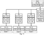
- fig. 11 shows another alternative control schematic implementing resiliency determination in the central control unit based on processing performed in the central and in a number of local control units
- fig. 12 shows a further alternative control schematic implementing resiliency determination in the central control unit and in a number of local control units.
- FIG. 9 depicts one control schematic of the considered microgrid. It can be seen that each microgrid asset has a local control unit which optimizes the operation of the corresponding asset based on the conditions of all microgrid assets as well as share the asset conditions with other microgrid assets.
- each microgrid asset is modelled in the local control unit with three main blocks representing the software SW, hardware HW, and communication CC of the studied asset.
- These three types of status data can together describe the conditions of each microgrid asset, e.g., loading rate, capacity level (for energy storage), maintenance history etc. Therefore, all of these three parts may be used in each microgrid asset to describe the asset situation with a so called "asset status index" indicating the availability, health and capacity.
- decision-making unit which implements the resiliency determining module
- Figure 9 the decision-making unit, which implements the resiliency determining module
- resiliency may be determined solely based on availability obtained through status data
- each asset in providing different desired functions may as was mentioned earlier be modelled through a set of indexes called function commitment indices.
- function commitment indices To simplify the calculation of commitment indices, the availability, health, capacity and relevance of each microgrid asset is presented through two indices, named asset status index St(i) and asset importance index Im(i, f). The former is obtained based on the three previously discussed fundamental parts defined for each microgrid asset (i.e., software, hardware, and communication), while the asset importance index Im(i, f), which is concerned with relevance, is determined based on the general situations of all microgrid assets and desired microgrid functionality.
- Figure 10 represents another way of operating the microgrid. It can be seen in this figure that the asset status index St. (i) is derived based on the asset internal conditions, while the asset importance index Im.(i,f) is determined inside the local control unit since it is also dependent to the conditions of other microgrid assets. The way these two indices may be calculated for each asset are more clearly explained in the following.
- the asset importance index Im.(i,f) can also vary for different microgrid functions, i.e. functions handling disruptive events, meaning that depending on the status of other components and also based on the number of assets which can provide different microgrid functions, the asset importance index of the studied asset might be different. For instance, assume the situation in which there are three or more assets in the microgrid (apart from the studied asset) that can provide microgrid function 1. However, the studied asset is the only asset in the microgrid that can provide function 2. In such situation, the asset importance index of the component for function 2 is much higher than the one for function 1. Accordingly, each microgrid asset has several asset importance indices depending on the number of considered microgrid functions.
- Figure 11 illustrates a proposed control schematic considering several microgrid functions.
- the asset status index St.(i) and the asset importance index Im.(i,f) may be calculated for each asset constantly.
- the asset status index St.(i) current and previous working conditions of all fundamental parts of each asset (i.e., software, hardware, and communication) may be evaluated and the asset status index is derived.
- Table I an example table (Table I) is suggested in the following. TABLE I Asset part Condition def.
- the asset importance index Im.(i,f) can also be calculated for each asset through a lookup table as the one suggested in Table 2.
- Table II Function no. Condition def. Conditions quantify Criticality value Power balance How many other assets can perform this function (P1) More than one 1 Only one more 2 No more 3 Placement in the MG regarding this function (P2) Not important 1 Important 2 Voltage control How many other assets can perform this function (V1) More than one 1 Only one more 2 No more 3 Placement in the MG regarding this function (V2) Not important 1 Important 2 Frequency control How many other assets can perform this function (F1) More than one 1 Only one more 2 No more 3 Placement in the MG regarding this function (F2) Not important 1 Important 2 Black start How many other assets can perform this function (B1) More than one 1 Only one more 2 No more 3 Placement in the MG regarding this function (B2) Not important 1 Important 2
- Table II MG is an abbreviation for Microgrid.
- the decision-making unit implementing the resiliency determining module will calculate the level of risk for the microgrid with respect to each function and based on the obtained value and some predefined threshold levels, will show appropriate alarming signals to the system operator.
- variables such as "More than one", “Only one more”, and “No more” in table II can have a dependence on the condition of the other assets.
- the importance index can in such an implementation have a decimal value to mark how bad the condition of the other parallel unit is.
- the resiliency determining module may be placed in any control unit. Also, the resiliency determining module may be placed in any control unit. However, it should be combined with the resiliency determining unit.
- the commitment determining module was above described as being distributed. It is provided in the different control units. It is as an alternative possible that there is one central commitment determining module placed in one of the control units, main or local. If this is done data that is used as input for determining a function commitment may then be provided to this control unit from all other control units.
- the arrangement comprises the modules involved in this determination such as the commitment determining modules, the resilience determining module and optionally also the data collection module and the resilience investigating module.
- the arrangement may also comprise the control units and in which these modules are implemented, such as the local control modules and the central control module.
- the modules may be realized as hardware modules, such as Application Specific Integrated Circuits (ASICs) and Field-Programmable Gate Arrays (FPGAs). However, as was mentioned above they may also be realized as software, i.e. computer program code.
- ASICs Application Specific Integrated Circuits
- FPGAs Field-Programmable Gate Arrays
- This computer program code used to implement the resiliency determining module, and the commitment determining modules and optionally also the data collecting module and the resiliency investigating module may also be provided on one or more data carriers which perform the activities of these modules when being operated on by a processor.
- Such a computer program may as an alternative be provided on a server and downloaded therefrom into a computer in order to obtain the system model creating and simulation device.
Landscapes
- Engineering & Computer Science (AREA)
- Power Engineering (AREA)
- Business, Economics & Management (AREA)
- General Physics & Mathematics (AREA)
- Physics & Mathematics (AREA)
- Health & Medical Sciences (AREA)
- Economics (AREA)
- Automation & Control Theory (AREA)
- Strategic Management (AREA)
- Primary Health Care (AREA)
- Marketing (AREA)
- Tourism & Hospitality (AREA)
- Human Resources & Organizations (AREA)
- General Business, Economics & Management (AREA)
- General Health & Medical Sciences (AREA)
- Theoretical Computer Science (AREA)
- Water Supply & Treatment (AREA)
- Public Health (AREA)
- Remote Monitoring And Control Of Power-Distribution Networks (AREA)
- Management, Administration, Business Operations System, And Electronic Commerce (AREA)
- Supply And Distribution Of Alternating Current (AREA)
Abstract
Description
- The invention relates to a method, arrangement and computer program product for determining resiliency in a microgrid.
- Microgrids are of interest to use for local power generation and consumption and for connection to a main grid. Such a microgrid can include a number of assets used for generating, storing and/or consuming electric energy. If the microgrid is considered to be a system, then an asset may be an electric subsystem into and/or from which power may be delivered.
- In a microgrid, it may be of interest to know about the resiliency with regard to disruptive events.
- Resiliency can be defined as: "the ability to reduce the magnitude and/or duration of disruptive events. The effectiveness of a resilient infrastructure or enterprise depends upon its ability to anticipate, absorb, adapt to, and/or rapidly recover from a potentially disruptive event". This definition is from the National Infrastructure Advisory Council NIAC) 2009, Critical Infrastructure Resilience Final Report and Recommendations.
- The resiliency may give support and facilitate in making decisions on adaptations of actions that can contribute to minimizing the recovery time in case of disruptive events (e.g. cyber attacks, disasters).
- There exist a number of documents describing the determining of resiliency.
-
US 2017/0040839 does for instance show a three level microgrid control architecture for ensuring stable operation in face of contingencies. A resiliency metric is calculated from multiple parameters including a current system state; and the system is determined to assume a contingency level based thereon. The contingency level is the basis of operational decisions to ensure the least possible disruption. -
US 2017/0046458 shows a system for performing power analytics on a microgrid through creating a virtual model of the grid's topology, measuring momentary parameters and simulating future events. The real-time measurements are to be compared to predicted values, deviations are assessed for severity and alarms are output for an operator if necessary. A system security index is calculated from various stability indices, showing the grid's ability to tolerate contingencies. -
CN 103903058A shows a smart grid monitoring and control method based on an extensive assessment index system comprising safety and emergency capacity metrics. The metrics help in planning and decision-making. - The above described resiliency determinations are all centralized and somewhat complicated. It would therefore be of interest to use another and above all simpler and decentralized approach to the determining of resiliency for the microgrid.
- One object of the invention is therefore to obtain an alternative way of determining the resiliency of a microgrid that is simple and fast as well as based on a decentralized approach.
- This object is according to a first aspect of the invention achieved through a method of determining resiliency in a microgrid comprising a number of assets, where each asset is a different type of electric energy subsystem in the microgrid, the method comprising:
- obtaining status data about devices used to control the assets as well as about communication resources of this control,
- determining, based on the status data, the health and availability of each asset to assist each of a plurality of functions for handling disruptive events in the microgrid, and
- determining a resiliency of the microgrid in performing the plurality of functions, the resiliency being determined based on the individual asset health and availability of each asset concerning all the functions for handling disruptive events.
- The object is according to a second aspect of the invention achieved through an arrangement for determining resiliency in a microgrid comprising a number of assets, where each asset is a different type of electric energy subsystem in the microgrid, the arrangement comprises at least one control unit configured to:
- obtain status data about devices used to control the assets as well as about communication resources of this control,
- determine, based on the status data, the health and availability of each asset to assist each of a plurality of functions for handling disruptive events in the microgrid, and
- determine a resiliency of the microgrid in performing said plurality of functions, the resiliency being determined based on the individual asset health and availability of each asset concerning all the functions for handling disruptive events.
- The object is according to a third aspect of the invention achieved through a computer program product for determining resiliency in a microgrid comprising a number of assets, where each asset is a different type of electric energy subsystem in the microgrid, the computer program product comprising a data carrier with computer program code configured to cause at least one control unit to, when the computer program code is loaded into the control unit
provide at least one commitment determining module arranged to obtain status data about devices used to control the assets as well as about communication resources of this control and determine, based on the status data, the health and availability of each asset to assist each of a plurality of functions for handling disruptive events in the microgrid, and provide at least one resiliency determining module arranged to determine a resiliency of the microgrid in performing said plurality of functions, the resiliency being determined based on the individual asset health and availability of each asset concerning all the functions for handling disruptive events. - The determining based on status data may thus comprise determining the health of each asset as well as the availability of each asset to assist each of a plurality of functions for handling disruptive events in the microgrid. This determination may additionally comprise the determining of the capacity of each asset to assist each of a plurality of functions for handling disruptive events in the microgrid.
- The microgrid may comprise a busbar to which the assets may be connected. In this case an asset may be a subsystem for receiving and/or delivering energy to the busbar.
- The assets may comprise at least one electric energy generating system. The assets may additionally or instead comprise at least one electric energy storing subsystem. The assets may additionally or instead comprise at least one electric energy consumption subsystem.
- The status data about the devices used to control the assets may comprise hardware status data and software status data.
- The status data may comprise status about inbuilt functionalities of the assets. This status data may be obtained through monitoring the inbuilt functionalities of the assets.
- The status data may be obtained from the devices that are used in the control of the asset. It may be integrated in components used for controlling the asset. Alternatively or instead status data may be obtained from outside of the microgrid, such as from third party providers and/or integrated in components.
- The determined resiliency may comprise a resiliency value for each of the plurality of functions for handling disruptive events. The determined resiliency may additionally or instead comprise a total resiliency value obtained through the individual resiliency values value for each of the plurality of functions for handling disruptive events. The resiliency may as an example be provided as a vector or matrix of resiliency values.
- The availability and health of an asset with regard to each of a plurality of functions for handling disruptive events in the microgrid may be provided as a number of values, where one value represents both the availability and health for one function The availability and health values may be provided in a vector or matrix. When the capacity is determined, one such value may represent the capacity in addition to the availability and health.
- According to a first variation of the first aspect, the method further comprises obtaining the relevance of each asset to each of the functions for handling disruptive events, wherein the resilience is determined also based on the relevance.
- According to a corresponding first variation of the second aspect, the at least one control unit is configured to obtain the relevance of each asset to each of the functions for handling disruptive events, wherein the at least one control unit when determining the resilience is further configured to determine the resilience also based on the relevance.
- Also the relevance of an asset to each of the functions may be provided as a number of values, one for each function.
- According to another variation, the method comprises determining, for each asset, a function commitment defining support given to the functions that handle disruptive events, where the function commitment of an asset comprises the availability, health, relevance and optionally also capacity for each of the plurality of functions that handle disruptive events. The functions that handle disruptive events may comprise at least one of a power balance function, a voltage control function, a frequency control function and a black start function.
- According to a corresponding variation of the second aspect the at least one control unit is configured to determine, for each asset, a function commitment defining support given to the functions that handle disruptive events, where the function commitment of an asset comprises the availability, health, relevance and optionally also capacity for each of the plurality of functions that handle disruptive events.
- The microgrid may be connected to an external grid via a circuit breaker.
- According to yet another variation of the first aspect, the obtaining of status data then comprises obtaining status data of the circuit breaker and the method comprises the further step of adjusting the relevance of at least one of the assets based on the status of the circuit breaker.
- According to a corresponding variation of the second aspect, the at least one control unit, when obtaining status data, is further configured to obtain status data of the circuit breaker and being further configured to adjust the relevance of at least one of the assets based on the status of the circuit breaker.
- The microgrid may furthermore have an overall control functionality.
- According to yet another variation of the first aspect, the obtaining of status data may then comprise obtaining status data also about the overall control functionality and the determining of the health, availability and optionally also capacity of each asset to assist each of a plurality of functions for handling disruptive events may be based also on the status data of the overall control functionality.
- According to a corresponding variation of the second aspect, the at least one control unit, when obtaining status data is further configured to obtain status data also about the overall control functionality and when determining the health, availability and optionally also capacity of each asset to assist each of a plurality of functions for handling disruptive events is further configured to determine this health, availability and optionally also capacity also based on the status data of the overall control functionality.
- The resiliency determination may include a determination of thresholds for resiliency values, where a threshold may be related to a too high a value or a too low a value.
- The determined resiliency and any associated thresholds may be provided to a control system for off-line and online decisions.
- The control system may be a system performing said above described overall control or a local control system of an asset. However, the control system may additionally be a remote control system, such as a virtual power plant for overall control.
- The resiliency and such thresholds may additionally be presented to an operator. These can be used as alarming signals for the different microgrid functions. Such alarming signals may optionally also allow the operator to make decisions in case there are unpredictable problems in the microgrid.
- The resilience and optionally also such thresholds may additionally be provided to an Energy Management System (EMS) for planning operation and maintenance of the microgrid.
- The resiliency may additionally be used in an automatic microgrid operation.
- In a further variation of the first aspect directed towards such automatic microgrid operation, the method further comprises
comparing the resiliency with a least one threshold and changing the control of the microgrid if any of the thresholds is crossed. In this case it is additionally possible that the resiliency is compared with a number of thresholds, one for each function for handling disruptive events and that the method further comprises selecting an asset to assist such a function for which the threshold has been crossed. - In a corresponding variation of the second aspect, the at least one control unit is further configured to compare the resiliency with a least one threshold and change the control of the microgrid if any of the thresholds is crossed. In this case it is additionally possible that the at least one control unit when comparing the resiliency is further configured to compare the resiliency with a number of thresholds, one for each function for handling disruptive events and being further configured to select an asset to assist such a function for which the threshold has been crossed based on the relevance of the asset to the function.
- The selecting of the asset may be based on the relevancy of the asset to the function. The selecting may additionally or instead be based on the health, availability and optionally also capacity of the asset in relation to the function.
- The determination of resiliency may be made continuously during the operation of the microgrid. The steps carried out for determining resiliency may thus be repeated regularly, such as cyclically.
- The invention has a number of advantages. It provides valuable information on resiliency. This results in supporting microgrid functions for many applications. It also allows proactive control of the microgrid where preventive measures can be taken to improve microgrid resiliency reducing restart time or preventing shutdown and/our outage. It could result in saving corrective and preventive maintenance costs, particularly after natural disaster or cyber attacks.
- The present invention will in the following be described with reference being made to the accompanying drawings, where
-
fig. 1 schematically shows a microgrid with a number of assets being controlled using a local and a central control unit, -
fig. 2 schematically shows one realization of the central control unit, -
fig. 3 schematically shows one realization of a local control unit, -
fig. 4 shows a flow chart of a number of method steps in a method of determining resiliency in the microgrid, -
fig. 5 schematically shows a flow chart of a number of method steps for using the determined resiliency in influencing the operation of the microgrid, -
fig. 6 shows data exchange between as well as various determinations being made by the central control unit and a local control unit, -
fig. 7 shows a calculation of a function commitment for different desired functions, -
fig. 8 shows the combination of all such received function commitments by the central control unit to assess resiliency, -
fig. 9 shows a control schematic implementing resiliency determination in the central control unit based on processing performed in the central and a number of local control units, -
fig. 10 shows an alternative control schematic implementing resiliency determination in the central control unit based on processing performed in the central and in a number of local control units, -
fig. 11 shows another alternative control schematic implementing resiliency determination in the central control unit based on processing performed in the central and in a number of local control units, -
fig. 12 shows a further alternative control schematic implementing resiliency determination in the central control unit and in a number of local control units, and -
fig. 13 shows a computer program product comprising a data carrier with computer program code, in the form of a CD-ROM disc, for implementing the resiliency determining and investigating functionality. - In the following, a detailed description of preferred embodiments of a system, method and computer program product for determining the resilience of a microgrid will be given.
-
Fig. 1 schematically shows amicrogrid 10 or main system and various control units for controlling themicrogrid 10. Themicrogrid 10 may be considered to be a system being made up of a number of subsystems. It therefore comprises abusbar 12 to which a number of subsystems are connected. In the following such subsystems are considered to be assets. There is a first subsystem orasset 14 connected to thebusbar 10 via afirst interface device 22, a second subsystem orasset 16 directly connected to thebusbar 12, a third subsystem orasset 18 also directly connected to thebusbar 10 and a fourth subsystem orasset 20 connected to thebusbar 12 via asecond interface device 24. Thebusbar 12 is also connected to a main orexternal grid 28 via anexternal grid interface 26, whichexternal grid interface 26 may comprise a circuit breaker. - An asset may be an electric energy subsystem in the
microgrid 12. An asset may therefore be as subsystem for receiving and/or delivering electric energy to thebusbar 12. - The
first asset 14 may be an electric energy storage system, such as a battery system. Thesecond asset 16 may be a first electric energy generating system, such as a diesel generator system, thethird asset 18 may be a controllable electrical load or electric energy consuming subsystem and thefourth asset 24 may be a second electric energy generating system, for instance in the form of a photovoltaic (PV) subsystem employing photovoltaic elements. - The
microgrid 10 may thus comprise at least one electric energy generating subsystem. Alternatively or additionally, the microgrid may comprise at least on electric energy storing subsystem. Alternatively or additionally, the microgrid may comprise at least one electric energy consuming subsystem - It should here be realized that it is possible with further assets, such as fifth asset that may be a third electric energy generating subsystem in the form of a wind farm, which may also be connected to the
busbar 12 via an interface device. Themicrogrid 10 may also comprise fewer subsystems. - The
busbar 12 may be an alternating current (AC) busbar. Some of the assets may be operating with direct current (DC) and these are then connected to thisbusbar 12 via an interface device comprising an AC/DC converter. Some other assets may be operating with AC and these may therefore be directly connected to the busbar. In the example given above thefirst asset 14 is an energy storage system operating with DC and therefore thefirst interface device 22 comprises an AC/DC converter. Thesecond asset 16 is a Diesel Generator system that operates with AC and may therefore be directly connected to thebusbar 12. Also, thethird asset 18, the load, operates with AC and may therefore also be directly connected to thebusbar 12. Thefourth asset 20, the PV subsystem, also operates with DC and therefore thesecond interface device 24 comprises an AC/DC converter. - It should be realized that the
busbar 12 may as an alternative be a DC busbar, in which case subsystems operating with DC may be directly connected to the busbar and the subsystems operating with AC may be connected via a DC/AC converter. The external ormain grid 28 may be an AC or a DC grid and depending on which type of grid it is and which type of busbar is used in the microgrid, theexternal grid interface 26 may comprise a suitable converter for converting between AC and DC. - It should additionally be realized that an AC subsystem may be connected to an AC busbar via an AC/AC converter and a DC subsystem may be connected to a DC busbar via a DC/DC converter.
- In order to control each asset of the
microgrid 10 for receiving and/or delivering energy, there is a corresponding local control unit comprising local control functionality. There is thus a firstlocal control unit 32 for controlling thefirst asset 14, a secondlocal control unit 34 for controlling thesecond asset 16, a thirdlocal control unit 36 for controlling thethird asset 18 and a fourthlocal control unit 38 for controlling thefourth asset 20. As thefirst asset 14 is exemplified by an electric energy storage system, thefirst control unit 32 may be a storage controller, as thesecond asset 16 is exemplified by a Diesel Generator system, the secondlocal control unit 34 may be a Diesel Controller, as thethird asset 18 is exemplified by a controllable electric load the thirdlocal control unit 36 may be a load controller and as thefourth asset 20 is exemplified by a PV Generation subsystem, the fourthlocal control unit 38 may be a PV controller. - Each local control unit also communicates with a
central control unit 30 or network controller, which is an overall control unit for themicrogrid 10 comprising functionality for overall control of themicrogrid 10. There is also anoperator terminal 40 connected to thecentral control unit 30, whichoperator terminal 40 may present information to a microgrid operator. In the figure one type of information in the form of a Resiliency indicator RI is shown as being provided by thecentral control unit 30 to theoperator terminal 40 for being presented. - In the figure the
local control units main control unit 30, which are indications of availability, health and relevance. - Each control unit may be realized as hardware such as a processor with associated memory and software, such as a control module comprising control functionality such as overall or local control functionality. The local control functionality may be provided for controlling a corresponding asset, i.e. to control a subsystem. Such control may comprise control to deliver electric energy to and/or from the subsystem. Some of the subsystems such as the Diesel Generator subsystem and the PV Generation subsystem may only be capable to deliver electric energy, some of the subsystems, such as the Controllable Load subsystem, may only be able to receive electric energy, while other systems such as the energy storage subsystem may be able to both deliver and receive electric energy.
- Each control unit may also have a communication interface for communication with other control units within the
microgrid 10 or entities outside of themicrogrid 10. -
Fig. 2 schematically shows one realization of thecentral control unit 30. Thecentral control unit 30 comprises hardware in the form of aprocessor PR 42 and an associated program memory M 44 comprising computer program instructions. The computer program instructions comprise instructions for realizing a main control module MCM with overall microgrid control functionality, instructions for realizing a resiliency determining module RDM, instructions for realizing a resilience investigating module RIM as well as optionally also instructions for realizing a data collection module DCM. The main control module MCM is an overall control module of the microgrid that considers individual control performed by the local control units. There is also a firstcommunication interface CI 46 connected to theprocessor 34 for allowing the main control module MCM to communicate with other control modules, such as local and external control modules. Also, the resiliency determining module RDM and perhaps also the resilience investigating module RIM may communicate via thiscommunication interface 46. - In a similar manner
fig. 3 schematically shows the realization of a local control unit, here exemplified by the firstlocal control unit 32. Thelocal control unit 32 comprises hardware in the form of aprocessor PR 48 and an associatedprogram memory M 50 comprising computer program instructions. The computer program instructions comprise instructions for realizing the above mentioned local control module LCM with local control functionality, which in the example given above is the energy storage control module. There is also here a commitment determining module CDM. Thelocal control unit 32 also comprises acommunication interface CI 52 connected to theprocessor 48 for allowing the local control module LCM to communicate with other control modules, such as the main or overall control module, external control modules, the data collection module and other commitment determination modules. Also the commitment determining module CDM may use thecommunication interface 52 for communicating with commitment determining modules of other local control units as well as with the resiliency determining module RDM, the data collection module DCM and possibly also with the resiliency investigating module RIM. - The exemplifying
microgrid 10 disclosed above has distributed control, where a local control unit optimizes the behaviour of the controlled subsystem to perform corresponding microgrid functions in the best manner. To achieve this goal, each asset should share its conditions with other assets through the local control unit. Thus, the local control unit for each asset has the possibility to make the best decision plan at each time based on the assigned functions in the microgrid as well as the conditions of all microgrid assets (including its own conditions). - As was mentioned earlier, resiliency to disruptive events is an important issue in such a microgrid. It is therefore of interest to determine a resiliency, perhaps as a resiliency indication, for instance in the form of a resiliency index, which indication may be used in an overall control or an Energy Management System (EMS).
- Resiliency requires a system perspective and situation awareness that can help to understand incidents as a complex imbedded process occurring at the intersection of natural and human forces across multiple scales, evolving and changing over time.
- One could summarize the key elements to improving resiliency of microgrids to be:
- Monitoring capacities of the assets with associated components and connectivity: hardware, software, communication etc. (e.g. state, functionality availability, environmental conditions, etc.)
- Situation awareness (ability to elaborate fast the data and extract valuable information about the occurring incidents and effective communication to the human operators that should take actions)
- Fast adaptation capacity (fully or partially automatized) of the microgrids configuration, production and load that can help to recover in minimized times.
- The microgrid system should thus be capable of determining resiliency for the microgrid operator based on the conditions such as health and capacity of the microgrid assets and on the availability of particular functionalities, which resiliency may be determined through determining resiliency indicators.
- Some of the important functions that are used to handle disruptive events and which a microgrid is expected to provide are as follows:
- Power balance
- Voltage control
- Frequency control
- Black start
- Resiliency is according to various aspects of the invention determined for a number of functions that handle disruptive events, which functions are therefore also termed disruptive event handling functions.
- According to various aspects of the invention, resiliency is determined based on an investigation into the status of the different types of assets. Each asset is thus investigated separately with regard to status and the impact of each asset on each disruptive event handling function may then be presented, for instance in one or more resiliency indicators. It is in addition possible that the status of the overall control functionality and/or the connection to the main grid via the circuit breaker in the
external grid interface 26 is investigated and the impact of one or both of these on the disruptive event handling functions considered. - How this may be done will now be described with reference being made also to
fig. 4 which shows a number of method steps in a method of determining resiliency for themicrogrid 10, which method steps are being performed by the resilience determining module RDM of thecentral control unit 30 and the different commitment determining modules CDM of the central andlocal control units - The method starts with each commitment determining module CDM associated with the
different assets step 54. Optionally also the data collection module DCM of thecentral control unit 30 obtains status data of the overall control functionality and/or the circuit breaker in the external grid interface. - This means that in the example system of
fig. 1 , the commitment determining module CDM being implemented by the firstlocal control unit 32 obtains status data related to thefirst asset 14, that the commitment determining module of the secondlocal control unit 34 obtains status data related to thesecond asset 16, that the commitment determining module of the thirdlocal control unit 32 obtains status data related to thethird asset 18 and that the commitment determining module of the fourthlocal control unit 38 obtains status data related to thefourth asset 20. Optionally also the commitment determining module CDM of thecentral control unit 30 obtains status data related to the main control module MCM and/or status data related to the circuit breaker in theexterna grid interface 26. The data collection module DCM may transmit status data it has collected to the commitment determining modules CDM of the local control units - The status data of an asset and of the overall control functionality, if used, may more particularly comprise status data concerning the performing of the control functionality. This is according to aspects of the invention data about devices used to implement the control modules, i.e. data about the
different control units 30 32, 34, 36 and 38 used to perform the overall control functionality and the local control functionality related to the assets. The status data may more particularly be data about the hardware and software of the control units. The status data of an asset thus comprises data about the processor and program memory of the local control unit controlling the asset as well as data about the local control modules LCM stored in these memories. The status data also comprises communication related data, which is data about the communication resources available for this local control module, which are the communication resources, such as the bandwidth, used by the communication interfaces of the local control units. The status data of the main control may in turn comprise data about the processor and program memory of the central control unit as well as data about the main control modules stored in these memories. The status data also comprises data about the communication resources, such as the bandwidth, available for this main control module, which are the communication resources used by the communication interface of the central control unit. The status data may comprise status about inbuilt functionalities of the assets, which may be obtained through the commitment determining module CDM monitoring the inbuilt functionalities of the assets. The status data may additionally be obtained from the devices that are used in the control of the asset. It may more particularly be integrated in components used for controlling the asset. Alternatively or instead, status data may be obtained from outside of the microgrid, such as from third party providers. - The status data of the circuit breaker may comprise data of if it is open or closed.
- In the example of the first
local control unit 32, the commitment determining module CDM thus obtains status data related to theprocessor 48 andmemory 50, status data about the local control module LCM as well as status data about the communication resources available to thecommunication interface 52. Optionally it also obtains status data related to theprocessor 42, memory 44 andcommunication interface 46 and/or the circuit breaker. - The device related status data may comprise limitations in the hardware and software in performing additional functions, such as limitations in remaining memory space. It may also comprise data about changes to the hardware and/or software as well as data about previous faults and failures. Asset related status data may comprise limitations in the control of the asset, such as available power, headroom and control modes as well as data about supported features.
- Based on this data a determination is then made of the availability, health and optionally also capacity, i.e. the contribution capability, of each asset to the disruptive event handling functions,
step 56. In this determination it is possible that the status data of the overall control functionality from the central control unit is also considered. - This means that in the example system of
fig. 1 , the commitment determining module CDM of the firstlocal control unit 32 determines the availability health and optionally also capacity of the first asset with regard to each of the disruptive event handling functions. This may involve determining available memory space and processing capability that may be assigned to disruptive event handling functions in relation to the asset in both the local control unit and the central control unit. In one variation this may involve equally assigning the excess capacity between the different disruptive event handling functions. The determining of availability, health and optional capacity may instead or in addition comprise investigating maintenance, loading and failure rate of hardware and software versions of software. The commitment determining module of the second, third and fourthlocal control units - It is additionally possible that the status data of the main control is transferred from the data collection module DCM of the
central control unit 30 to the different commitment determining modules of the local control units in order to be considered in determining the availability of the individual assets to each of the disruptive event handling functions. The status of the hardware, software and communication capability of the central control unit may be combined with the status the hardware, software and communication capability of a local control unit in order to determine the availability of the asset for the different functions. - The health of an asset and the availability and capacity of this asset to assist the disruptive event handling functions may be provided as a number of values, one for each function, for instance in the form of a vector. The above-mentioned healths, availabilities and optional capacities may additionally be expressed as degrees of health, availability and capacity to the disruptive event handling functions, for instance in the form of percentages., where a percentage may be formed in respect of the heath, availability and capacity
- Thereafter an optional step of obtaining the importance or relevance of each asset and optionally also the main control and/or circuit breaker to each disruptive event handling function may be performed,
step 58. The commitment determining module CDM of the firstlocal control unit 32 may thus obtain the relevance of the first asset to each of the functions, the commitment determining module of the secondlocal control unit 34 may obtain the relevance of the second asset to each of the disruptive event handling functions, the commitment determining module of the thirdlocal control unit 36 may obtain the relevance of thethird asset 18 to each of the disruptive event handling functions and the commitment determining module of the fourthlocal control unit 38 may obtain the relevance of the fourth asset to each of the disruptive event handling functions. These may be pre-determined and stored as relevance values in a relevance table. - The relevance of an asset to the disruptive event handling functions may thus be provided as a number of values, one for each function. The relevancies may additionally be expressed as degrees of relevance to the disruptive event handling functions, for instance in the form of percentages, for instance in a vector.
- It is possible that an asset cannot be used for a function. This may be reflected by the relevance. An asset may also be unable to accommodate processing requirements for performing or assisting in performing the disruptive event handling function, which may also influence the relevance. It is furthermore possible that the relevance of an asset may influence the availability. The availability of an asset that has a low relevance for one function may be higher for other functions that it has some relevance to. An asset that is not able to implement a disruptive event handling function may have zero availability for this function and thereby availability with regard to other disruptive event handling functions that it is able to participate in may be increased.
- Take the function of frequency control for instance, as the
first asset 14 uses DC, it cannot be employed for assisting this function. The relevance of thefirst asset 14 for this function may therefore be zero. - The same can be said for capacity, an asset that does not have the capacity may also be unable to assist a fault handling function. A fully charged energy storage system may for instance not be able to receive any additional energy. It may thereby have zero capacity for a function that needs to store energy. The relevance to this function may therefore be zero. For a function that requires energy, the relevance may instead be high.
- The relevance and/or availability of an asset for a function may also be influenced by the status of the circuit breaker in the
external grid interface 26. The relevance of an asset for an event handling function may more particularly be adjusted based on the status of the circuit breaker. The status of the circuit breaker may be relevant for all disruptive event handling functions that require the use of the external main grid but lacks relevance for disruptive event handling functions that do not. Therefore the relevance of an asset for a disruptive event handling function requiring a connection to the main grid may be set to zero if the status of the circuit breaker is that it is open. - The different commitment determining modules CDM of the different
local control units central control unit 30. This measure may be a function commitment, which is a commitment made by the commitment determining module CDM that may specify if and in what degree the asset may be used in handling the different disruptive event handling functions. As is discussed above the status of the main control and/or the circuit breaker may be used in the determining of the function commitments made by the commitment determining modules of the local control units. - The first
local control unit 32 therefore transfers a first function commitment FC1, the secondlocal control unit 34 transfers a second function commitment FC2, the thirdlocal control unit 36 transfers third function commitment FC3 and the fourthlocal control unit 38 transfers a fourth function commitment FC4 to the resilience determining module RDM in thecentral control unit 30 via the communication interfaces 46 and 52. - Thereafter the resilience determining module RDM determines the resilience of the microgrid in relation to each disruptive event handling function based on the received function commitments, i.e. based on the health, availability, capacity and relevance of each asset in relation to each of the disruptive event handling functions,
step 60. This resiliency may be provided in the form of one or more resiliency indicators RI, for instance realized as a resiliency index, provided to theoperator terminal 40. - If there are four disruptive event handling functions, this may involve combining the healths, availabilities, capacities and relevancies determined by all the commitment determining modules in relation to the first disruptive event handling function into a first resilience value, combining the healths, availabilities, capacities and relevancies determined by all the commitment determining modules in relation to the second disruptive event handling function into a second resilience value, combining the healths, availabilities, capacities and relevancies determined by the commitment determining modules in relation to the third disruptive event handling function into a third resilience value and combining the healths, availabilities, capacities and relevancies determined by the commitment determining modules in relation to the fourth disruptive event handling function into a fourth resilience value. The resilience values for the different disruptive event handling functions may then be combined into a system resilience indication RI provided to the
operator terminal 40 for being presented to an operator. The resiliency indicator RI may be in the form of one or more values, for instance as a vector or a matrix, where in the case of a vector one value may be provided for each disruptive event handling function. In the case of a matrix each position in the matrix may correspond to the resiliency of an asset in relation to a function. A row in the matrix may therefore correspond to a function, while a column may correspond to an asset. - The resiliency determination may additionally include a determination of borders or thresholds for the total value and/or for the individual resiliency values, where a border may be related to a too high a value or a too low a value.
- The resiliency and optionally the corresponding borders or thresholds may additionally be presented to an operator for use as alarming signals for the different microgrid functions. Such alarming signals may optionally also allow the operator to make decisions in case there are unpredictable problems in the microgrid.
- The resilience and optionally also such thresholds may additionally be provided to an EMS system for planning operation and maintenance of the microgrid.
- The resiliency may additionally be used in an automatic microgrid operation.
- When being presented to an operator, the operator may act on the resilience indication RI or any of the individual resilience values if these are outside of the borders or thresholds set for the resilience.
- It should be realized that the determination of resiliency may be made continuously. The above-mentioned method steps may therefore be repeated regularly, such as cyclically.
- The operator may thereby evaluate the microgrid resiliency through the defined and desired microgrid functions. Moreover, the assessment results could be used to provide appropriate alarming signals to the microgrid operator for the different microgrid functions.
- When resiliency is used in an automatic microgrid operation, it is possible that the
central control unit 30 uses the resilience investigating module RIM. The operation of this module will now be described with reference being made tofig. 5 , which shows a number of method steps for performing the investigation. - The resilience investigation module RIM may compare the resiliency with at least one threshold,
step 62. This may involve comparing each determined resiliency with a corresponding resiliency threshold. The comparing may as an example involve comparing the overall resiliency value with a threshold and/or one or more of the individual resiliency values determined for the disruptive event handling functions with corresponding thresholds. If no threshold is crossed,step 64, then operation of the microgrid is continued in the same way as before the investigation. However, if any threshold is crossed,step 64, the control of themicrogrid 10 is changed in order to improve the resilience,step 66. This improvement may involve the resilience investigation module RIM informing the main control module MCM about which disruptive event handling function needs to have its resiliency increased. It may additionally involve selecting one or more asset that is to assist in the increasing of the resiliency, which selection may be based on the relevancies of the assets. It is for instance possible to select and use the asset having the highest relevance with the highest possible health, availability and optionally also capacity. It is also possible that the selection is based on the healths, availabilities and optionally also capacities of the asset. The main control module MCM may then change the operation of one or more of the assets, such as the selected assets, that have an influence on this resiliency. This may involve ordering a local control unit to change the control of the corresponding asset. - Through the provision of a measure of the resiliency of a microgrid, for instance in the form of a resiliency indicator, it will be possible to implement fully or partially automatized adaptation actions (e.g. Reconfiguration, islanding, load shedding, etc.) It may also minimize the recovery time and cost of the microgrids in case of disasters or unpredictable disruptive events (e.g. Extreme weather events, cyber-attacks, etc.).
- Now one specific variation of the handling of resiliency will be described with reference being made to
fig. 6 ,7 and 8 , wherefig. 6 shows data exchange between the central control unit and a local control unit,fig. 7 shows a calculation of a function commitment for different desired functions in the local control unit andfig. 8 shows the combination of all such commitments by the central control unit to assess resiliency. - 1. Each health, availability and optional capacity or asset state may be characterized by a set of indices, St(i), named "asset status index". St(i) may be an array of scalar indices. Each index denotes over a scale (e.g. from 0 till 5, 0% to 100%, etc) the health state of the monitored characteristics of the asset (e.g. hardware and communication state, control modes and supported features, available stored energy, etc.).
- 2. The asset status indices St(i) (part of it or all) determined by a commitment determining module CDM of a local control unit may be broadcast to the other commitment determining modules of the other local control units and to the resiliency determining module RDM of the
central control unit 30. The resiliency determining module of thecentral control unit 30 has the task of monitoring the status indices of the network and the breaker in theinterface 26, - 3. Each local control unit calculates a Function Commitment, for instance in the form of a "Function Commitment index", (FC1, FC2, FC3 and FC4 in
Figure 1 ) based on a functionality, health, availability and capacity model of all assets, for the asset controlled (e.g. energy storage, diesel generator, PV, etc.). In addition to availability, health and capacity, the commitment indexes of an asset indicate its ability of performing various operation features based also on the condition of the studied asset as well as the conditions of the other assets in the grid, i.e., other components, network, and limits. - A suggested way to calculate the commitment is as an index, which is provided in equation (1), in which F(Asset i, Functions j) provides the contribution of Asset i in providing function j, and SAsset represents the status or availability of different microgrid assets:

- For instance, the commitment of Diesel Generator in providing the Power Balance could be computed through:

- Each local control unit calculates commitment indices for the different disruptive event handling functions F1, F2, F3 that the specific asset is supposed to participate in (e.g. Power balance, Voltage Control, Frequency Control, Black Start, etc.). The calculation considers hardware, software, communication availability, health and capacity such as control limits, such as headroom and limit and available power and modes, such as local control modes and supported features. An explanatory example is shown in
Figure 7 . For the implementation of the function commitment module, it may be required to implement failure limits and network checks,Figure 7 , which define the thresholds of the status index that indicate a condition of anomaly of clear fault conditions. - The failure investigation may comprise investigating communication failure, hardware and software failure, power limits and network structure.
- 4. Following the design principle of distributed control, the function commitment indexes of asset i in function j, i.e., F(i,j), of each microgrid asset is broadcast to all the other local control units and to the central control unit. Broadcasting limitations can be implemented if needed. The
central control unit 30,Figure 8 , operates as data aggregator and it has also the task of monitoring the network and breaker function commitment index and broadcast them to all the local control units. - 5. In the
central control unit 30 the resiliency indexes are finally calculated,Figure 8 . The resiliency determining module has as input the function commitment Indexes, F(i,j), collected from all the local control units and gives as output a set of scalar indexes, the resiliency indexes. - For each function (e.g. power balance, frequency control and voltage control, black start, etc.) needed for the recovery of the microgrid in case of a disruptive event, the microgrid resiliency is evaluated a ranking of all the assets that can provide such function on a scalar index (e.g. 0%-100%).
- That is to say, the resiliency of the microgrid with respect to function j may be calculated through the following equation:

- These indexes are communicated in a concise and effective way to the microgrid operator via the
operator terminal 40. For each resiliency index an automatic alarm threshold can be implemented in the central control unit and communicated to the microgrid operator. - In case of disaster the Microgrid Operator can have information for each function needed for the restoration about:
- Availability of restoration functionalities in the microgrid
- Which assets can perform such functionalities
- Indications on the derating of the assets after a disaster
- Which assets need priority in repairing interventions
- The operator and/or the central control unit finally can make decision on the adaptations actions that can contribute to minimize the recovery time in case of disruptive events.
- The main benefits of the proposed scheme can be summarized as follows:
- 1. The most important advantage of the proposed approach is that it provides valuable information on resiliency. This results in supporting microgrid functions for many applications.
- 2. It will also provide smarter control of the microgrid where preventive measures can be taken to improve microgrid resiliency reducing restart time.
- 3. It could result in saving a huge amount of corrective and preventive maintenance costs, particularly after natural disaster or cyber attacks.
- Further implementation examples will now be given with reference being made to
fig. 9. 10 ,11 and12 , wherefig. 9 shows a control schematic implementing resiliency determination in the central control unit based on processing performed in the central and in a number of local control units,fig. 10 shows an alternative control schematic implementing resiliency determination in the central control unit based on processing performed in the central and in a number of local control units,fig. 11 shows another alternative control schematic implementing resiliency determination in the central control unit based on processing performed in the central and in a number of local control units, andfig. 12 shows a further alternative control schematic implementing resiliency determination in the central control unit and in a number of local control units. -
Figure 9 depicts one control schematic of the considered microgrid. It can be seen that each microgrid asset has a local control unit which optimizes the operation of the corresponding asset based on the conditions of all microgrid assets as well as share the asset conditions with other microgrid assets. - It can be seen in
Figure 9 that each microgrid asset is modelled in the local control unit with three main blocks representing the software SW, hardware HW, and communication CC of the studied asset. These three types of status data can together describe the conditions of each microgrid asset, e.g., loading rate, capacity level (for energy storage), maintenance history etc. Therefore, all of these three parts may be used in each microgrid asset to describe the asset situation with a so called "asset status index" indicating the availability, health and capacity. - Please also note that the decision-making unit, which implements the resiliency determining module, is presented in
Figure 9 as a separate unit. As an alternative it could be included in any of the local control units as well as in the central control unit. It can be seen that resiliency may be determined solely based on availability obtained through status data - The contribution of each asset in providing different desired functions may as was mentioned earlier be modelled through a set of indexes called function commitment indices. To simplify the calculation of commitment indices, the availability, health, capacity and relevance of each microgrid asset is presented through two indices, named asset status index St(i) and asset importance index Im(i, f). The former is obtained based on the three previously discussed fundamental parts defined for each microgrid asset (i.e., software, hardware, and communication), while the asset importance index Im(i, f), which is concerned with relevance, is determined based on the general situations of all microgrid assets and desired microgrid functionality.
-
Figure 10 represents another way of operating the microgrid. It can be seen in this figure that the asset status index St. (i) is derived based on the asset internal conditions, while the asset importance index Im.(i,f) is determined inside the local control unit since it is also dependent to the conditions of other microgrid assets. The way these two indices may be calculated for each asset are more clearly explained in the following. - It should also be noted that the asset importance index Im.(i,f) can also vary for different microgrid functions, i.e. functions handling disruptive events, meaning that depending on the status of other components and also based on the number of assets which can provide different microgrid functions, the asset importance index of the studied asset might be different. For instance, assume the situation in which there are three or more assets in the microgrid (apart from the studied asset) that can provide
microgrid function 1. However, the studied asset is the only asset in the microgrid that can providefunction 2. In such situation, the asset importance index of the component forfunction 2 is much higher than the one forfunction 1. Accordingly, each microgrid asset has several asset importance indices depending on the number of considered microgrid functions.Figure 11 illustrates a proposed control schematic considering several microgrid functions. - In addition, a control schematic which considers several microgrid functions as well as distributed control concept is presented in
Figure 12 . In the schematic depicted in this figure, there are more than one local control unit that can perform the decision-making process. - It should be emphasized that in both
Figures 11 and12 , the local control units which perform the decision-making process should present the required warning signals to the microgrid operator. - In operation, the asset status index St.(i) and the asset importance index Im.(i,f) may be calculated for each asset constantly. To calculate the asset status index St.(i), current and previous working conditions of all fundamental parts of each asset (i.e., software, hardware, and communication) may be evaluated and the asset status index is derived. To illustrate this index calculation more clearly, an example table (Table I) is suggested in the following.
TABLE I Asset part Condition def. Conditions quantify Criticality value Software status Program version (S1) New version 1 Old version 2 Any software problem since last checkup (S2) No 1 Yes 2 Hardware status Time since last maintenance (H1) < 5 years 1 ≥ 5 years 2 Average loading since last < 80 % 1 maintenance (H2) ≥ 80 % 2 Initial failure rate (H3) < 0.2 f/ year 1 ≥ 0.2 f/ year 2 Communication status Communication Technology (C1) Type 11 Type 22 Any software problem since last checkup (C2) No 1 Yes 2 - According to this table:
- Software status is equal to S1 + S2 and can vary between 2 and 4.
- Hardware status is equal to H1 + H2 + H3 and can vary between 3 and 6.
- Communication status is equal to C1 + C2 and can vary between 2 and 4.
- Asset status index St. (i) is equal to S1 + S2 + H1 + H2 + H3 + C1 + C2 and can vary between 7 and 14.
- Please note that the proposed value and items in this table are mere examples for illustrating the availability and relevance of assets.
- Similar to the asset status index calculation, the asset importance index Im.(i,f) can also be calculated for each asset through a lookup table as the one suggested in Table 2.
Table II Function no. Condition def. Conditions quantify Criticality value Power balance How many other assets can perform this function (P1) More than one 1 Only one more 2 No more 3 Placement in the MG regarding this function (P2) Not important 1 Important 2 Voltage control How many other assets can perform this function (V1) More than one 1 Only one more 2 No more 3 Placement in the MG regarding this function (V2) Not important 1 Important 2 Frequency control How many other assets can perform this function (F1) More than one 1 Only one more 2 No more 3 Placement in the MG regarding this function (F2) Not important 1 Important 2 Black start How many other assets can perform this function (B1) More than one 1 Only one more 2 No more 3 Placement in the MG regarding this function (B2) Not important 1 Important 2 - In Table II MG is an abbreviation for Microgrid.
- According to this table:
- The asset importance index Im.(i,f) with respect to any of these four functions is equal to X1 + X2 and can vary between 2 and 5, where X could be P, V, F, or B.
- According to the above described operation, all asset status indices and asset importance indices of all assets are used in the next step to calculate the resiliency of the microgrid with respect to each desired function. Resilience is here determined as a Resiliency Index. To do so, the following equation may be used:


- Using these equations, the decision-making unit implementing the resiliency determining module will calculate the level of risk for the microgrid with respect to each function and based on the obtained value and some predefined threshold levels, will show appropriate alarming signals to the system operator.
- In a more advanced form of calculation for the importance index, variables such as "More than one", "Only one more", and "No more" in table II can have a dependence on the condition of the other assets. As an example, if two components are the only ones supporting function one, then there are More than one assets available. If however one of these assets have a high risk of failure due to a bad maintenance condition, then the other asset will become more important, as there are now "No more" assets that can provide this function securely. The importance index can in such an implementation have a decimal value to mark how bad the condition of the other parallel unit is.
- There are a number of further variations that are possible to make to the microgrid described above. As could be seen the resiliency determining module may be placed in any control unit. Also, the resiliency determining module may be placed in any control unit. However, it should be combined with the resiliency determining unit.
- The commitment determining module was above described as being distributed. It is provided in the different control units. It is as an alternative possible that there is one central commitment determining module placed in one of the control units, main or local. If this is done data that is used as input for determining a function commitment may then be provided to this control unit from all other control units.
- One aspect of the invention is concerned with an arrangement for determining resiliency. The arrangement comprises the modules involved in this determination such as the commitment determining modules, the resilience determining module and optionally also the data collection module and the resilience investigating module. The arrangement may also comprise the control units and in which these modules are implemented, such as the local control modules and the central control module.
- The modules may be realized as hardware modules, such as Application Specific Integrated Circuits (ASICs) and Field-Programmable Gate Arrays (FPGAs). However, as was mentioned above they may also be realized as software, i.e. computer program code.
- This computer program code used to implement the resiliency determining module, and the commitment determining modules and optionally also the data collecting module and the resiliency investigating module may also be provided on one or more data carriers which perform the activities of these modules when being operated on by a processor. One
such data carrier 70 with the previously mentionedcomputer program code 72, in the form of a CD ROM disc, is schematically shown infig. 13 . Such a computer program may as an alternative be provided on a server and downloaded therefrom into a computer in order to obtain the system model creating and simulation device. - While the invention has been described in connection with what is presently considered to be most practical and preferred, it is to be realized that the invention is not to be limited to the disclosed embodiments, but on the contrary, is intended to cover various modifications and equivalent arrangements. The invention is only to be limited by the following claims.
Claims (15)
- A method of determining resiliency in a microgrid (10) comprising a number of assets (14, 16, 18, 20), where each asset is a different type of electric energy subsystem in the microgrid, the method comprising:obtaining (54) status data about devices (32, 34, 36, 38) used to control the assets as well as about communication resources of this control,determining (56), based on the status data, the health and availability of each asset to assist each of a plurality of functions (F1, F2, F3) for handling disruptive events in the microgrid, anddetermining (60) a resiliency (RI) of said microgrid in performing said plurality of functions (F1, F2, F3), the resiliency being determined based on the individual asset health and availability of each asset (14, 16, 18, 20) concerning all the functions (F1, F2, F3) for handling disruptive events.
- The method according to claim 1, wherein the determining based on status data also comprises determining the capacity of each asset to assist each of a plurality of functions for handling disruptive events in the microgrid.
- The method according to claim 1 or 2, wherein the functions that handle disruptive events comprise at least one of a power balance function, a voltage control function, a frequency control function and a black start function.
- The method according to any previous claim, wherein the determined resiliency comprises a resiliency value for each of the plurality of functions (F1, F2, F3) for handling disruptive events.
- The method according to any previous claim, further comprising obtaining (58) the relevance of each asset (14, 16, 18, 20) to each of the functions (F1, F2, F3) for handling disruptive events, wherein the resilience (RI) is determined also based on said relevance.
- The method according to claim 5, wherein the microgrid (12) is connected to an external grid (28) via a circuit breaker (26), the obtaining of status data comprises obtaining status data of the circuit breaker and further comprising adjusting the relevance of at least one of the assets based on the status of the circuit breaker.
- The method according to any previous claim, wherein the microgrid (10) has an overall control functionality (MCF) and the obtaining of status data comprises obtaining status data also about the overall control functionality and the determining of the health and availability of each asset to assist each of a plurality of functions for handling disruptive events is based also on the status data of the overall control functionality.
- The method according to any previous claim, wherein the status data about the devices used to control the assets comprises hardware status data and software status data.
- The method according to any previous claim, further comprising providing the resiliency to an energy management system.
- The method according to any previous claim, wherein the resiliency is provided to a control system of the microgrid.
- The method according to claim 10, further comprising comparing (62), in the control system, the resiliency (RI) with a least one threshold and changing (66) the control of the microgrid (10) if any of the thresholds is crossed.
- The method according to claim 11 when depending on claim 5, wherein the resiliency is compared with a number of thresholds, one for each function for handling disruptive events and further comprising selecting an asset to assist such a function for which the threshold has been crossed.
- The method according to any of claims 10 - 12, wherein the control system is a remote control system.
- An arrangement for determining resiliency in a microgrid (10) comprising a number of assets (14, 16, 18, 20), where each asset is a different type of electric energy subsystem in the microgrid, the arrangement comprises at least one control unit (30 32, 34, 36, 38) configured to:obtain status data about devices (32, 34, 36, 38) used to control the assets as well as about communication resources of this control, determine, based on the status data, the health and availability of each asset to assist each of a plurality of functions (F1, F2, F3) for handling disruptive events in the microgrid, anddetermine a resiliency (RI) of said microgrid in performing said plurality of functions (F1, F2, F3), the resiliency being determined based on the individual asset health and availability of each asset (14, 16, 18, 20) concerning all the functions (F1, F2, F3) for handling disruptive events.
- A computer program product for determining resiliency in a microgrid (10) comprising a number of assets (14, 16, 18, 20), where each asset is a different type of electric energy subsystem in the microgrid, said computer program product comprising a data carrier (70) with computer program code (72) configured to cause at least one control unit (30, 32, 34, 36, 38) to, when said computer program code is loaded into said control unit (30, 32, 34, 36, 38)
provide at least one commitment determining module (CDM) arranged to obtain status data about devices (32, 34, 36, 38) used to control the assets as well as about communication resources of this control and determine, based on the status data, the health and availability of each asset to assist each of a plurality of functions (F1, F2, F3) for handling disruptive events in the microgrid, and
provide at least one resiliency determining module (RDM) arranged to determine a resiliency (RI) of said microgrid in performing said plurality of functions (F1, F2, F3), the resiliency being determined based on the individual asset health and availability of each asset (14, 16, 18, 20) concerning all the functions (F1, F2, F3) for handling disruptive events.
Priority Applications (6)
| Application Number | Priority Date | Filing Date | Title |
|---|---|---|---|
| EP18195383.7A EP3627433B1 (en) | 2018-09-19 | 2018-09-19 | Resiliency determination in a microgrid |
| JP2021515085A JP7032608B2 (en) | 2018-09-19 | 2019-09-10 | Judgment of resilience in the microgrid |
| AU2019343715A AU2019343715B2 (en) | 2018-09-19 | 2019-09-10 | Resiliency determination in a microgrid |
| CN201980060693.4A CN112714991B (en) | 2018-09-19 | 2019-09-10 | Measurement of micro-grid toughness |
| US17/276,277 US11163281B2 (en) | 2018-09-19 | 2019-09-10 | Resiliency determination in a microgrid |
| PCT/EP2019/074111 WO2020058040A1 (en) | 2018-09-19 | 2019-09-10 | Resiliency determination in a microgrid |
Applications Claiming Priority (1)
| Application Number | Priority Date | Filing Date | Title |
|---|---|---|---|
| EP18195383.7A EP3627433B1 (en) | 2018-09-19 | 2018-09-19 | Resiliency determination in a microgrid |
Publications (2)
| Publication Number | Publication Date |
|---|---|
| EP3627433A1 true EP3627433A1 (en) | 2020-03-25 |
| EP3627433B1 EP3627433B1 (en) | 2021-11-24 |
Family
ID=63642810
Family Applications (1)
| Application Number | Title | Priority Date | Filing Date |
|---|---|---|---|
| EP18195383.7A Active EP3627433B1 (en) | 2018-09-19 | 2018-09-19 | Resiliency determination in a microgrid |
Country Status (6)
| Country | Link |
|---|---|
| US (1) | US11163281B2 (en) |
| EP (1) | EP3627433B1 (en) |
| JP (1) | JP7032608B2 (en) |
| CN (1) | CN112714991B (en) |
| AU (1) | AU2019343715B2 (en) |
| WO (1) | WO2020058040A1 (en) |
Families Citing this family (3)
| Publication number | Priority date | Publication date | Assignee | Title |
|---|---|---|---|---|
| US11133675B2 (en) * | 2020-01-21 | 2021-09-28 | Enphase Energy, Inc. | Method and apparatus for synchronizing start-up of grid-forming inverters |
| US20250253663A1 (en) * | 2023-02-03 | 2025-08-07 | Aes Us Services, Llc | System and method of bess control for bulk power system monitoring and control |
| US20260045792A1 (en) * | 2024-08-07 | 2026-02-12 | Caterpillar Inc. | Microgrid health detection |
Citations (5)
| Publication number | Priority date | Publication date | Assignee | Title |
|---|---|---|---|---|
| CN103903058A (en) | 2012-12-26 | 2014-07-02 | 中国电力科学研究院 | Assessment method of efficient operation of intelligent power distribution network |
| US20150331063A1 (en) * | 2014-05-13 | 2015-11-19 | Georgia Tech Research Corporation | Dynamic Modeling and Resilience for Power Distribution |
| US20170040839A1 (en) | 2014-04-22 | 2017-02-09 | Siemens Aktiengesellschaft | Flexible control architecture for microgrid resiliency |
| US20170046458A1 (en) | 2006-02-14 | 2017-02-16 | Power Analytics Corporation | Systems and methods for real-time dc microgrid power analytics for mission-critical power systems |
| WO2017067585A1 (en) * | 2015-10-21 | 2017-04-27 | Abb Schweiz Ag | A method to improve microgrid stability with mgc controllers |
Family Cites Families (8)
| Publication number | Priority date | Publication date | Assignee | Title |
|---|---|---|---|---|
| US8655939B2 (en) * | 2007-01-05 | 2014-02-18 | Digital Doors, Inc. | Electromagnetic pulse (EMP) hardened information infrastructure with extractor, cloud dispersal, secure storage, content analysis and classification and method therefor |
| US8468244B2 (en) * | 2007-01-05 | 2013-06-18 | Digital Doors, Inc. | Digital information infrastructure and method for security designated data and with granular data stores |
| US7991512B2 (en) * | 2007-08-28 | 2011-08-02 | General Electric Company | Hybrid robust predictive optimization method of power system dispatch |
| EP2535714A1 (en) * | 2011-06-16 | 2012-12-19 | Istituto Nazionale Di Genetica Molecolare-INGM | Biomarkers for autoimmune liver diseases and uses thereof |
| JP5781257B2 (en) * | 2013-08-30 | 2015-09-16 | 京セラ株式会社 | Distributed power system, power conditioner |
| CN104269873B (en) * | 2014-09-28 | 2016-06-29 | 东南大学 | Based on system health state estimation and the micro-capacitance sensor autonomous control method using for reference CSMA/CD mechanism |
| US20170244252A1 (en) * | 2016-02-23 | 2017-08-24 | Nec Laboratories America, Inc. | Autonomous Operational Platform for Micro-Grid Energy Management |
| DK3424122T3 (en) * | 2016-03-03 | 2021-04-12 | Abb Power Grids Switzerland Ag | POWER CONTROL OF A MICRONET |
-
2018
- 2018-09-19 EP EP18195383.7A patent/EP3627433B1/en active Active
-
2019
- 2019-09-10 JP JP2021515085A patent/JP7032608B2/en active Active
- 2019-09-10 US US17/276,277 patent/US11163281B2/en active Active
- 2019-09-10 WO PCT/EP2019/074111 patent/WO2020058040A1/en not_active Ceased
- 2019-09-10 AU AU2019343715A patent/AU2019343715B2/en active Active
- 2019-09-10 CN CN201980060693.4A patent/CN112714991B/en active Active
Patent Citations (5)
| Publication number | Priority date | Publication date | Assignee | Title |
|---|---|---|---|---|
| US20170046458A1 (en) | 2006-02-14 | 2017-02-16 | Power Analytics Corporation | Systems and methods for real-time dc microgrid power analytics for mission-critical power systems |
| CN103903058A (en) | 2012-12-26 | 2014-07-02 | 中国电力科学研究院 | Assessment method of efficient operation of intelligent power distribution network |
| US20170040839A1 (en) | 2014-04-22 | 2017-02-09 | Siemens Aktiengesellschaft | Flexible control architecture for microgrid resiliency |
| US20150331063A1 (en) * | 2014-05-13 | 2015-11-19 | Georgia Tech Research Corporation | Dynamic Modeling and Resilience for Power Distribution |
| WO2017067585A1 (en) * | 2015-10-21 | 2017-04-27 | Abb Schweiz Ag | A method to improve microgrid stability with mgc controllers |
Non-Patent Citations (4)
| Title |
|---|
| CHANDA SAYONSOM ET AL: "Quantifying power distribution system resiliency using code based metric", 2016 IEEE INTERNATIONAL CONFERENCE ON POWER ELECTRONICS, DRIVES AND ENERGY SYSTEMS (PEDES), IEEE, 14 December 2016 (2016-12-14), pages 1 - 6, XP033090164, DOI: 10.1109/PEDES.2016.7914553 * |
| CHANDA SAYONSOM ET AL: "Quantifying resiliency of smart power distribution systems with distributed energy resources", 2015 IEEE 24TH INTERNATIONAL SYMPOSIUM ON INDUSTRIAL ELECTRONICS (ISIE), IEEE, 3 June 2015 (2015-06-03), pages 766 - 771, XP033223033, DOI: 10.1109/ISIE.2015.7281565 * |
| CHI YUAN ET AL: "A State-of-the-Art Literature Survey of Power Distribution System Resilience Assessment", 2018 IEEE POWER & ENERGY SOCIETY GENERAL MEETING (PESGM), IEEE, 5 August 2018 (2018-08-05), pages 1 - 5, XP033482644, DOI: 10.1109/PESGM.2018.8586495 * |
| KRISHNAMURTHY VAIDYANATHAN ET AL: "Effects of Power Electronics, Energy Storage, Power Distribution Architecture, and Lifeline Dependencies on Microgrid Resiliency During Extreme Events", IEEE JOURNAL OF EMERGING AND SELECTED TOPICS IN POWER ELECTRONICS, IEEE, PISCATAWAY, NJ, USA, vol. 4, no. 4, 1 December 2016 (2016-12-01), pages 1310 - 1323, XP011626950, ISSN: 2168-6777, [retrieved on 20161028], DOI: 10.1109/JESTPE.2016.2598648 * |
Also Published As
| Publication number | Publication date |
|---|---|
| CN112714991B (en) | 2024-08-06 |
| US20210247732A1 (en) | 2021-08-12 |
| WO2020058040A1 (en) | 2020-03-26 |
| AU2019343715B2 (en) | 2022-04-21 |
| US11163281B2 (en) | 2021-11-02 |
| JP7032608B2 (en) | 2022-03-08 |
| EP3627433B1 (en) | 2021-11-24 |
| AU2019343715A1 (en) | 2021-05-20 |
| JP2021529503A (en) | 2021-10-28 |
| CN112714991A (en) | 2021-04-27 |
Similar Documents
| Publication | Publication Date | Title |
|---|---|---|
| Shen et al. | Distributed risk-limiting load restoration in unbalanced distribution systems with networked microgrids | |
| US8504214B2 (en) | Self-healing power grid and method thereof | |
| Poudel et al. | A generalized framework for service restoration in a resilient power distribution system | |
| Farzin et al. | Role of outage management strategy in reliability performance of multi-microgrid distribution systems | |
| Elmitwally et al. | A fuzzy-multiagent service restoration scheme for distribution system with distributed generation | |
| US7203622B2 (en) | Value-based transmission asset maintenance management of electric power networks | |
| US7194338B2 (en) | Voltage collapse diagnostic and ATC system | |
| US11163281B2 (en) | Resiliency determination in a microgrid | |
| Cifuentes et al. | Network allocation of BESS with voltage support capability for improving the stability of power systems | |
| Dehghanian | Power system topology control for enhanced resilience of smart electricity grids | |
| Wang et al. | Optimal capacity planning for manufacturing, transportation, and replacement of quickly-detachable transformer modules in substations of resilient distribution networks | |
| Kumar et al. | Power system resilience quantification and enhancement strategy for real-time operation | |
| Alsheryani et al. | Applying artificial intelligence (AI) for predictive maintenance of power distribution networks: A case study of al ain distribution company | |
| Kumar et al. | A robust approach to resiliency enhancement of distribution system using ensembled deep reinforcement learning | |
| Shao et al. | Quantum-enabled topological optimization of distributed energy storage for resilient black-start operations | |
| Hosseinzadeh et al. | Fast restoration of microgrids using online evaluation metrics considering severe windstorms | |
| Tiwari et al. | Electrical digital twins–enabled smart grid | |
| Li et al. | Sensitivity factors based transmission network topology control for violation relief | |
| Stewart et al. | Integrated multi-scale data analytics and machine learning for the distribution grid and building-to-grid interface | |
| Valencia et al. | Asset management model of SCADA infrastructure of power control centers based on indicators | |
| Abanihi et al. | Modeling and evaluation of system reliability for auchi distribution network | |
| Dai et al. | AI-driven resilience analysis of distribution networks under extreme events | |
| Varshnry et al. | Supply energy management methods for a direct current microgrid: A comprehensive review | |
| Dialynas et al. | Modelling and evaluation of microgrids reliability and operational performance and its impact on service quality | |
| Gonzalez-Reina et al. | Enhanced Resilience of Microgrids Through Distributed Open Ring Topologies and Advanced Model Predictive Control Techniques |
Legal Events
| Date | Code | Title | Description |
|---|---|---|---|
| PUAI | Public reference made under article 153(3) epc to a published international application that has entered the european phase |
Free format text: ORIGINAL CODE: 0009012 |
|
| STAA | Information on the status of an ep patent application or granted ep patent |
Free format text: STATUS: THE APPLICATION HAS BEEN PUBLISHED |
|
| AK | Designated contracting states |
Kind code of ref document: A1 Designated state(s): AL AT BE BG CH CY CZ DE DK EE ES FI FR GB GR HR HU IE IS IT LI LT LU LV MC MK MT NL NO PL PT RO RS SE SI SK SM TR |
|
| AX | Request for extension of the european patent |
Extension state: BA ME |
|
| RAP1 | Party data changed (applicant data changed or rights of an application transferred) |
Owner name: ABB POWER GRIDS SWITZERLAND AG |
|
| STAA | Information on the status of an ep patent application or granted ep patent |
Free format text: STATUS: REQUEST FOR EXAMINATION WAS MADE |
|
| 17P | Request for examination filed |
Effective date: 20200925 |
|
| RBV | Designated contracting states (corrected) |
Designated state(s): AL AT BE BG CH CY CZ DE DK EE ES FI FR GB GR HR HU IE IS IT LI LT LU LV MC MK MT NL NO PL PT RO RS SE SI SK SM TR |
|
| RIC1 | Information provided on ipc code assigned before grant |
Ipc: H02J 13/00 20060101ALN20201209BHEP Ipc: H02J 3/32 20060101ALN20201209BHEP Ipc: G06Q 50/06 20120101AFI20201209BHEP Ipc: H02J 3/00 20060101ALI20201209BHEP Ipc: H02J 3/38 20060101ALI20201209BHEP |
|
| GRAP | Despatch of communication of intention to grant a patent |
Free format text: ORIGINAL CODE: EPIDOSNIGR1 |
|
| STAA | Information on the status of an ep patent application or granted ep patent |
Free format text: STATUS: GRANT OF PATENT IS INTENDED |
|
| INTG | Intention to grant announced |
Effective date: 20210115 |
|
| GRAJ | Information related to disapproval of communication of intention to grant by the applicant or resumption of examination proceedings by the epo deleted |
Free format text: ORIGINAL CODE: EPIDOSDIGR1 |
|
| STAA | Information on the status of an ep patent application or granted ep patent |
Free format text: STATUS: REQUEST FOR EXAMINATION WAS MADE |
|
| INTC | Intention to grant announced (deleted) | ||
| RIC1 | Information provided on ipc code assigned before grant |
Ipc: G06Q 50/06 20120101AFI20210512BHEP Ipc: H02J 3/00 20060101ALI20210512BHEP Ipc: H02J 3/38 20060101ALI20210512BHEP Ipc: H02J 3/32 20060101ALN20210512BHEP Ipc: H02J 13/00 20060101ALN20210512BHEP |
|
| GRAP | Despatch of communication of intention to grant a patent |
Free format text: ORIGINAL CODE: EPIDOSNIGR1 |
|
| STAA | Information on the status of an ep patent application or granted ep patent |
Free format text: STATUS: GRANT OF PATENT IS INTENDED |
|
| INTG | Intention to grant announced |
Effective date: 20210624 |
|
| GRAS | Grant fee paid |
Free format text: ORIGINAL CODE: EPIDOSNIGR3 |
|
| GRAA | (expected) grant |
Free format text: ORIGINAL CODE: 0009210 |
|
| STAA | Information on the status of an ep patent application or granted ep patent |
Free format text: STATUS: THE PATENT HAS BEEN GRANTED |
|
| RAP3 | Party data changed (applicant data changed or rights of an application transferred) |
Owner name: HITACHI ENERGY SWITZERLAND AG |
|
| AK | Designated contracting states |
Kind code of ref document: B1 Designated state(s): AL AT BE BG CH CY CZ DE DK EE ES FI FR GB GR HR HU IE IS IT LI LT LU LV MC MK MT NL NO PL PT RO RS SE SI SK SM TR |
|
| REG | Reference to a national code |
Ref country code: GB Ref legal event code: FG4D |
|
| REG | Reference to a national code |
Ref country code: AT Ref legal event code: REF Ref document number: 1450445 Country of ref document: AT Kind code of ref document: T Effective date: 20211215 |
|
| REG | Reference to a national code |
Ref country code: DE Ref legal event code: R096 Ref document number: 602018027064 Country of ref document: DE |
|
| REG | Reference to a national code |
Ref country code: IE Ref legal event code: FG4D |
|
| REG | Reference to a national code |
Ref country code: LT Ref legal event code: MG9D |
|
| REG | Reference to a national code |
Ref country code: NL Ref legal event code: MP Effective date: 20211124 |
|
| REG | Reference to a national code |
Ref country code: AT Ref legal event code: MK05 Ref document number: 1450445 Country of ref document: AT Kind code of ref document: T Effective date: 20211124 |
|
| PG25 | Lapsed in a contracting state [announced via postgrant information from national office to epo] |
Ref country code: RS Free format text: LAPSE BECAUSE OF FAILURE TO SUBMIT A TRANSLATION OF THE DESCRIPTION OR TO PAY THE FEE WITHIN THE PRESCRIBED TIME-LIMIT Effective date: 20211124 Ref country code: LT Free format text: LAPSE BECAUSE OF FAILURE TO SUBMIT A TRANSLATION OF THE DESCRIPTION OR TO PAY THE FEE WITHIN THE PRESCRIBED TIME-LIMIT Effective date: 20211124 Ref country code: FI Free format text: LAPSE BECAUSE OF FAILURE TO SUBMIT A TRANSLATION OF THE DESCRIPTION OR TO PAY THE FEE WITHIN THE PRESCRIBED TIME-LIMIT Effective date: 20211124 Ref country code: BG Free format text: LAPSE BECAUSE OF FAILURE TO SUBMIT A TRANSLATION OF THE DESCRIPTION OR TO PAY THE FEE WITHIN THE PRESCRIBED TIME-LIMIT Effective date: 20220224 Ref country code: AT Free format text: LAPSE BECAUSE OF FAILURE TO SUBMIT A TRANSLATION OF THE DESCRIPTION OR TO PAY THE FEE WITHIN THE PRESCRIBED TIME-LIMIT Effective date: 20211124 |
|
| PG25 | Lapsed in a contracting state [announced via postgrant information from national office to epo] |
Ref country code: IS Free format text: LAPSE BECAUSE OF FAILURE TO SUBMIT A TRANSLATION OF THE DESCRIPTION OR TO PAY THE FEE WITHIN THE PRESCRIBED TIME-LIMIT Effective date: 20220324 Ref country code: SE Free format text: LAPSE BECAUSE OF FAILURE TO SUBMIT A TRANSLATION OF THE DESCRIPTION OR TO PAY THE FEE WITHIN THE PRESCRIBED TIME-LIMIT Effective date: 20211124 Ref country code: PT Free format text: LAPSE BECAUSE OF FAILURE TO SUBMIT A TRANSLATION OF THE DESCRIPTION OR TO PAY THE FEE WITHIN THE PRESCRIBED TIME-LIMIT Effective date: 20220324 Ref country code: PL Free format text: LAPSE BECAUSE OF FAILURE TO SUBMIT A TRANSLATION OF THE DESCRIPTION OR TO PAY THE FEE WITHIN THE PRESCRIBED TIME-LIMIT Effective date: 20211124 Ref country code: NO Free format text: LAPSE BECAUSE OF FAILURE TO SUBMIT A TRANSLATION OF THE DESCRIPTION OR TO PAY THE FEE WITHIN THE PRESCRIBED TIME-LIMIT Effective date: 20220224 Ref country code: NL Free format text: LAPSE BECAUSE OF FAILURE TO SUBMIT A TRANSLATION OF THE DESCRIPTION OR TO PAY THE FEE WITHIN THE PRESCRIBED TIME-LIMIT Effective date: 20211124 Ref country code: LV Free format text: LAPSE BECAUSE OF FAILURE TO SUBMIT A TRANSLATION OF THE DESCRIPTION OR TO PAY THE FEE WITHIN THE PRESCRIBED TIME-LIMIT Effective date: 20211124 Ref country code: HR Free format text: LAPSE BECAUSE OF FAILURE TO SUBMIT A TRANSLATION OF THE DESCRIPTION OR TO PAY THE FEE WITHIN THE PRESCRIBED TIME-LIMIT Effective date: 20211124 Ref country code: GR Free format text: LAPSE BECAUSE OF FAILURE TO SUBMIT A TRANSLATION OF THE DESCRIPTION OR TO PAY THE FEE WITHIN THE PRESCRIBED TIME-LIMIT Effective date: 20220225 Ref country code: ES Free format text: LAPSE BECAUSE OF FAILURE TO SUBMIT A TRANSLATION OF THE DESCRIPTION OR TO PAY THE FEE WITHIN THE PRESCRIBED TIME-LIMIT Effective date: 20211124 |
|
| PG25 | Lapsed in a contracting state [announced via postgrant information from national office to epo] |
Ref country code: SM Free format text: LAPSE BECAUSE OF FAILURE TO SUBMIT A TRANSLATION OF THE DESCRIPTION OR TO PAY THE FEE WITHIN THE PRESCRIBED TIME-LIMIT Effective date: 20211124 Ref country code: SK Free format text: LAPSE BECAUSE OF FAILURE TO SUBMIT A TRANSLATION OF THE DESCRIPTION OR TO PAY THE FEE WITHIN THE PRESCRIBED TIME-LIMIT Effective date: 20211124 Ref country code: RO Free format text: LAPSE BECAUSE OF FAILURE TO SUBMIT A TRANSLATION OF THE DESCRIPTION OR TO PAY THE FEE WITHIN THE PRESCRIBED TIME-LIMIT Effective date: 20211124 Ref country code: EE Free format text: LAPSE BECAUSE OF FAILURE TO SUBMIT A TRANSLATION OF THE DESCRIPTION OR TO PAY THE FEE WITHIN THE PRESCRIBED TIME-LIMIT Effective date: 20211124 Ref country code: DK Free format text: LAPSE BECAUSE OF FAILURE TO SUBMIT A TRANSLATION OF THE DESCRIPTION OR TO PAY THE FEE WITHIN THE PRESCRIBED TIME-LIMIT Effective date: 20211124 Ref country code: CZ Free format text: LAPSE BECAUSE OF FAILURE TO SUBMIT A TRANSLATION OF THE DESCRIPTION OR TO PAY THE FEE WITHIN THE PRESCRIBED TIME-LIMIT Effective date: 20211124 |
|
| REG | Reference to a national code |
Ref country code: DE Ref legal event code: R097 Ref document number: 602018027064 Country of ref document: DE |
|
| PLBE | No opposition filed within time limit |
Free format text: ORIGINAL CODE: 0009261 |
|
| STAA | Information on the status of an ep patent application or granted ep patent |
Free format text: STATUS: NO OPPOSITION FILED WITHIN TIME LIMIT |
|
| PG25 | Lapsed in a contracting state [announced via postgrant information from national office to epo] |
Ref country code: AL Free format text: LAPSE BECAUSE OF FAILURE TO SUBMIT A TRANSLATION OF THE DESCRIPTION OR TO PAY THE FEE WITHIN THE PRESCRIBED TIME-LIMIT Effective date: 20211124 |
|
| 26N | No opposition filed |
Effective date: 20220825 |
|
| PG25 | Lapsed in a contracting state [announced via postgrant information from national office to epo] |
Ref country code: SI Free format text: LAPSE BECAUSE OF FAILURE TO SUBMIT A TRANSLATION OF THE DESCRIPTION OR TO PAY THE FEE WITHIN THE PRESCRIBED TIME-LIMIT Effective date: 20211124 |
|
| PG25 | Lapsed in a contracting state [announced via postgrant information from national office to epo] |
Ref country code: MC Free format text: LAPSE BECAUSE OF FAILURE TO SUBMIT A TRANSLATION OF THE DESCRIPTION OR TO PAY THE FEE WITHIN THE PRESCRIBED TIME-LIMIT Effective date: 20211124 |
|
| REG | Reference to a national code |
Ref country code: CH Ref legal event code: PL |
|
| REG | Reference to a national code |
Ref country code: BE Ref legal event code: MM Effective date: 20220930 |
|
| PG25 | Lapsed in a contracting state [announced via postgrant information from national office to epo] |
Ref country code: LU Free format text: LAPSE BECAUSE OF NON-PAYMENT OF DUE FEES Effective date: 20220919 |
|
| P01 | Opt-out of the competence of the unified patent court (upc) registered |
Effective date: 20230527 |
|
| PG25 | Lapsed in a contracting state [announced via postgrant information from national office to epo] |
Ref country code: LI Free format text: LAPSE BECAUSE OF NON-PAYMENT OF DUE FEES Effective date: 20220930 Ref country code: IE Free format text: LAPSE BECAUSE OF NON-PAYMENT OF DUE FEES Effective date: 20220919 Ref country code: CH Free format text: LAPSE BECAUSE OF NON-PAYMENT OF DUE FEES Effective date: 20220930 |
|
| PG25 | Lapsed in a contracting state [announced via postgrant information from national office to epo] |
Ref country code: BE Free format text: LAPSE BECAUSE OF NON-PAYMENT OF DUE FEES Effective date: 20220930 |
|
| PG25 | Lapsed in a contracting state [announced via postgrant information from national office to epo] |
Ref country code: HU Free format text: LAPSE BECAUSE OF FAILURE TO SUBMIT A TRANSLATION OF THE DESCRIPTION OR TO PAY THE FEE WITHIN THE PRESCRIBED TIME-LIMIT; INVALID AB INITIO Effective date: 20180919 |
|
| REG | Reference to a national code |
Ref country code: DE Ref legal event code: R081 Ref document number: 602018027064 Country of ref document: DE Owner name: HITACHI ENERGY LTD, CH Free format text: FORMER OWNER: HITACHI ENERGY SWITZERLAND AG, BADEN, CH |
|
| PG25 | Lapsed in a contracting state [announced via postgrant information from national office to epo] |
Ref country code: CY Free format text: LAPSE BECAUSE OF FAILURE TO SUBMIT A TRANSLATION OF THE DESCRIPTION OR TO PAY THE FEE WITHIN THE PRESCRIBED TIME-LIMIT Effective date: 20211124 |
|
| PG25 | Lapsed in a contracting state [announced via postgrant information from national office to epo] |
Ref country code: MK Free format text: LAPSE BECAUSE OF FAILURE TO SUBMIT A TRANSLATION OF THE DESCRIPTION OR TO PAY THE FEE WITHIN THE PRESCRIBED TIME-LIMIT Effective date: 20211124 |
|
| REG | Reference to a national code |
Ref country code: GB Ref legal event code: 732E Free format text: REGISTERED BETWEEN 20240718 AND 20240724 |
|
| PG25 | Lapsed in a contracting state [announced via postgrant information from national office to epo] |
Ref country code: MT Free format text: LAPSE BECAUSE OF FAILURE TO SUBMIT A TRANSLATION OF THE DESCRIPTION OR TO PAY THE FEE WITHIN THE PRESCRIBED TIME-LIMIT Effective date: 20211124 |
|
| REG | Reference to a national code |
Ref country code: DE Ref legal event code: R082 Ref document number: 602018027064 Country of ref document: DE Representative=s name: DENNEMEYER & ASSOCIATES RECHTSANWALTSGESELLSCH, DE |
|
| PGFP | Annual fee paid to national office [announced via postgrant information from national office to epo] |
Ref country code: DE Payment date: 20250919 Year of fee payment: 8 |
|
| PGFP | Annual fee paid to national office [announced via postgrant information from national office to epo] |
Ref country code: IT Payment date: 20250923 Year of fee payment: 8 |
|
| PGFP | Annual fee paid to national office [announced via postgrant information from national office to epo] |
Ref country code: GB Payment date: 20250919 Year of fee payment: 8 |
|
| PGFP | Annual fee paid to national office [announced via postgrant information from national office to epo] |
Ref country code: FR Payment date: 20250922 Year of fee payment: 8 |
|
| PG25 | Lapsed in a contracting state [announced via postgrant information from national office to epo] |
Ref country code: TR Free format text: LAPSE BECAUSE OF FAILURE TO SUBMIT A TRANSLATION OF THE DESCRIPTION OR TO PAY THE FEE WITHIN THE PRESCRIBED TIME-LIMIT Effective date: 20211124 |