EP3627281A1 - Thermal management via virtual bmc manager - Google Patents
Thermal management via virtual bmc manager Download PDFInfo
- Publication number
- EP3627281A1 EP3627281A1 EP18215319.7A EP18215319A EP3627281A1 EP 3627281 A1 EP3627281 A1 EP 3627281A1 EP 18215319 A EP18215319 A EP 18215319A EP 3627281 A1 EP3627281 A1 EP 3627281A1
- Authority
- EP
- European Patent Office
- Prior art keywords
- management controller
- virtual
- thermally sensitive
- bmc
- management
- Prior art date
- Legal status (The legal status is an assumption and is not a legal conclusion. Google has not performed a legal analysis and makes no representation as to the accuracy of the status listed.)
- Granted
Links
Images



Classifications
-
- G—PHYSICS
- G06—COMPUTING OR CALCULATING; COUNTING
- G06F—ELECTRIC DIGITAL DATA PROCESSING
- G06F1/00—Details not covered by groups G06F3/00 - G06F13/00 and G06F21/00
- G06F1/16—Constructional details or arrangements
- G06F1/20—Cooling means
- G06F1/206—Cooling means comprising thermal management
-
- G—PHYSICS
- G05—CONTROLLING; REGULATING
- G05B—CONTROL OR REGULATING SYSTEMS IN GENERAL; FUNCTIONAL ELEMENTS OF SUCH SYSTEMS; MONITORING OR TESTING ARRANGEMENTS FOR SUCH SYSTEMS OR ELEMENTS
- G05B19/00—Program-control systems
- G05B19/02—Program-control systems electric
- G05B19/18—Numerical control [NC], i.e. automatically operating machines, in particular machine tools, e.g. in a manufacturing environment, so as to execute positioning, movement or co-ordinated operations by means of program data in numerical form
- G05B19/406—Numerical control [NC], i.e. automatically operating machines, in particular machine tools, e.g. in a manufacturing environment, so as to execute positioning, movement or co-ordinated operations by means of program data in numerical form characterised by monitoring or safety
-
- G—PHYSICS
- G05—CONTROLLING; REGULATING
- G05B—CONTROL OR REGULATING SYSTEMS IN GENERAL; FUNCTIONAL ELEMENTS OF SUCH SYSTEMS; MONITORING OR TESTING ARRANGEMENTS FOR SUCH SYSTEMS OR ELEMENTS
- G05B19/00—Program-control systems
- G05B19/02—Program-control systems electric
- G05B19/18—Numerical control [NC], i.e. automatically operating machines, in particular machine tools, e.g. in a manufacturing environment, so as to execute positioning, movement or co-ordinated operations by means of program data in numerical form
- G05B19/4155—Numerical control [NC], i.e. automatically operating machines, in particular machine tools, e.g. in a manufacturing environment, so as to execute positioning, movement or co-ordinated operations by means of program data in numerical form characterised by program execution, i.e. part program or machine function execution, e.g. selection of a program
-
- G—PHYSICS
- G06—COMPUTING OR CALCULATING; COUNTING
- G06F—ELECTRIC DIGITAL DATA PROCESSING
- G06F1/00—Details not covered by groups G06F3/00 - G06F13/00 and G06F21/00
- G06F1/16—Constructional details or arrangements
- G06F1/20—Cooling means
-
- G—PHYSICS
- G06—COMPUTING OR CALCULATING; COUNTING
- G06F—ELECTRIC DIGITAL DATA PROCESSING
- G06F11/00—Error detection; Error correction; Monitoring
- G06F11/30—Monitoring
- G06F11/3003—Monitoring arrangements specially adapted to the computing system or computing system component being monitored
- G06F11/3024—Monitoring arrangements specially adapted to the computing system or computing system component being monitored where the computing system component is a central processing unit [CPU]
-
- G—PHYSICS
- G06—COMPUTING OR CALCULATING; COUNTING
- G06F—ELECTRIC DIGITAL DATA PROCESSING
- G06F11/00—Error detection; Error correction; Monitoring
- G06F11/30—Monitoring
- G06F11/3058—Monitoring arrangements for monitoring environmental properties or parameters of the computing system or of the computing system component, e.g. monitoring of power, currents, temperature, humidity, position, vibrations
-
- G—PHYSICS
- G06—COMPUTING OR CALCULATING; COUNTING
- G06F—ELECTRIC DIGITAL DATA PROCESSING
- G06F9/00—Arrangements for program control, e.g. control units
- G06F9/06—Arrangements for program control, e.g. control units using stored programs, i.e. using an internal store of processing equipment to receive or retain programs
- G06F9/44—Arrangements for executing specific programs
- G06F9/455—Emulation; Interpretation; Software simulation, e.g. virtualisation or emulation of application or operating system execution engines
- G06F9/45533—Hypervisors; Virtual machine monitors
-
- G—PHYSICS
- G05—CONTROLLING; REGULATING
- G05B—CONTROL OR REGULATING SYSTEMS IN GENERAL; FUNCTIONAL ELEMENTS OF SUCH SYSTEMS; MONITORING OR TESTING ARRANGEMENTS FOR SUCH SYSTEMS OR ELEMENTS
- G05B2219/00—Program-control systems
- G05B2219/30—Nc systems
- G05B2219/49—Nc machine tool, till multiple
- G05B2219/49206—Compensation temperature, thermal displacement, use measured temperature
-
- G—PHYSICS
- G06—COMPUTING OR CALCULATING; COUNTING
- G06F—ELECTRIC DIGITAL DATA PROCESSING
- G06F9/00—Arrangements for program control, e.g. control units
- G06F9/06—Arrangements for program control, e.g. control units using stored programs, i.e. using an internal store of processing equipment to receive or retain programs
- G06F9/44—Arrangements for executing specific programs
- G06F9/455—Emulation; Interpretation; Software simulation, e.g. virtualisation or emulation of application or operating system execution engines
- G06F9/45533—Hypervisors; Virtual machine monitors
- G06F9/45558—Hypervisor-specific management and integration aspects
- G06F2009/45579—I/O management, e.g. providing access to device drivers or storage
-
- Y—GENERAL TAGGING OF NEW TECHNOLOGICAL DEVELOPMENTS; GENERAL TAGGING OF CROSS-SECTIONAL TECHNOLOGIES SPANNING OVER SEVERAL SECTIONS OF THE IPC; TECHNICAL SUBJECTS COVERED BY FORMER USPC CROSS-REFERENCE ART COLLECTIONS [XRACs] AND DIGESTS
- Y02—TECHNOLOGIES OR APPLICATIONS FOR MITIGATION OR ADAPTATION AGAINST CLIMATE CHANGE
- Y02D—CLIMATE CHANGE MITIGATION TECHNOLOGIES IN INFORMATION AND COMMUNICATION TECHNOLOGIES [ICT], I.E. INFORMATION AND COMMUNICATION TECHNOLOGIES AIMING AT THE REDUCTION OF THEIR OWN ENERGY USE
- Y02D10/00—Energy efficient computing, e.g. low power processors, power management or thermal management
Definitions
- the present invention relates to computer systems and non-transitory computer readable mediums for establishing a virtual a Baseboard Management Controller (BMC) to receive temperature information from individual electronic units within a computing device.
- BMC Baseboard Management Controller
- the various components making up a computer system typically operate within a range of parameters defined by performance protocols or standards. For instance, the temperature within a computer chassis is often monitored to detect when the system may rise above a predetermined temperature reading.
- Other forms of information that may be monitored within a computer system include, without limitation, voltages associated with semiconductor components located on the baseboard of the system; velocity (e.g., rpm) of cooling fans located on the baseboard or within the system chassis; and the velocity of spindle motors within hard disk drives or optical drives.
- a computer system typically employs one or more management modules to assist in the collection and analysis of information sensed by the various sensors measuring operating and performance-related parameters within the system.
- management modules may be either software or hardware components, but typically encompass both hardware and software components that are implemented by service processors.
- One such management module is referred to as a "Baseboard Management Controller” (BMC).
- BMC Baseboard Management Controller
- the BMC is a microcontroller integrated into the baseboard (also known in the industry as the "motherboard") of a computer system, and having a specified number of contact pins through which information sensed by various sensors is received for analysis by the BMC.
- the BMC is programmed with firmware for implementing procedures relating to system monitoring and recovery.
- firmware the BMC is programmed to monitor various operating and performance-related parameters sensed within a computer system.
- the BMC is also programmed to analyze this information to determine whether any of the sensed parameters are currently outside of an expected or recommended operating range, the occurrence of which is commonly referred to as an "event.”
- the BMC is unable to communicate directly with the hardware components.
- the hardware components may have an integrated system that detects when its temperature is approaching predetermined threshold levels that would cause lack of performance or catastrophic failure.
- the integrated system of the hardware components is not connected to a fan system within the computer systems, thereby making the fan system inefficient. Therefore, there is a need to provide a computer system that establishes a connection between the BMC and the hardware components.
- a method of thermal management in a computing device using a management controller includes obtaining, via a virtual management controller, monitoring information of a thermally sensitive component untethered to the management controller.
- the monitoring information can include temperature information of the thermally sensitive component.
- the method also includes transmitting, via the virtual management controller, the monitoring information to the management controller via a system interface of the management controller.
- the method includes adjusting, via the management controller, the operation of a thermal management component of the computing device tethered to the management controller.
- the monitoring information for the thermally sensitive component includes identification information. Furthermore, the monitoring information for the thermally sensitive component can include a slowdown temperature, a shutdown temperature, and a current temperature. In some embodiments, the thermally sensitive component can include a graphics processing unit. In addition, a virtual baseboard management controller manager can be implemented to manage messages received at the management controller from two or more virtual management controllers.
- the management controller can be a baseboard management controller.
- the thermal management component can be a fan device.
- the virtual management controller can be a virtual baseboard management controller.
- a computer system for thermal management of a computing device using a management controller can include a thermally sensitive component, specifically a management controller that includes a system interface.
- the management controller can be untethered to the thermally sensitive component.
- the system can also include a thermal management component tethered to the management controller and a virtual management controller.
- the virtual management controller can be configured to obtain monitoring information of the thermally sensitive component untethered to the management controller.
- the monitoring information can include temperature information of the thermally sensitive component.
- the virtual management controller can also be configured to transmit the monitoring information to the management controller via the system interface of the management controller.
- the virtual management controller can be configured to adjust operation of the thermal management component tethered to the management controller.
- a non-transitory computer readable medium that stores instructions executable by at least one processor is also provided.
- the stored instructions can include obtaining, via a virtual management controller, monitoring information of a thermally sensitive component untethered to the management controller.
- the monitoring information can include temperature information of the thermally sensitive component.
- the method also includes transmitting, via the virtual management controller, the monitoring information to the management controller via a system interface of the management controller.
- the method includes adjusting, via the management controller, operation of a thermal management component of the computing device tethered to the management controller.
- the present application teaches a method and computer system for thermal management in a computing device using a management controller.
- the method includes obtaining, via a virtual management controller, monitoring information of a thermally sensitive component untethered to the management controller.
- the monitoring information can include temperature information of the thermally sensitive component.
- the method also includes transmitting, via the virtual management controller, the monitoring information to the management controller via a system interface of the management controller.
- the method includes adjusting, via the management controller, operation of a thermal management component of the computing device tethered to the management controller.
- FIG. 1 schematically depicts a conventional computer system 100.
- the computer system 100 has central processing units (CPU) 107.
- the CPUs 107 are standard central processors that perform arithmetic and logical operations necessary for the operation of the computer system 100.
- the CPUs 107 can be connected to graphic processor units (GPU) 108.
- GPU graphic processor units
- the GPUs 108 dissipate heat while operating.
- the computer system 100 can provide fans 106 to cool off the GPUs 108 after the GPUs 108 reach a prescribed temperature.
- the GPUs 108 can be in communication with a management bus 130 of the host computer system 100 to provide information regarding the GPUs' health, operation, and performance conditions to the BMC 104. Such information can include the GPU voltage and temperature.
- Each GPU 108 can be connected to sensors (not shown) measuring the electrical component's health, operation, and performance-related parameters through, for example, the management bus 130. This information can be sent to the BMC 104 by way of the management bus 130.
- the BMC 104 is also communicatively coupled by way of the management bus 130 to the fans 106 to control functionality over the fans 106.
- the component that initiates communication on a bus is referred to as a master, and the component to which the communication is sent is referred to as a slave.
- the BMC component 104 typically functions as the master on the management bus 130, but may also function as either a master or a slave in other circumstances.
- Each of the various components communicatively connected to the BMC 104 by way of the management bus 130 can be addressed using a slave address.
- the management bus 130 is used by the BMC 104 to request and/or receive various health, operation, and performance-related parameters from one or more components, which can be also communicatively connected to the management bus 130. In FIG.
- the management bus 130 communicatively connects the BMC 104 to the GPUS 108 (and its temperature sensor (not shown)) and the CPU fans 106, thereby providing a means for the BMC 104 to monitor and/or control operation of these components.
- the management bus 130 can typically include tachometers, heat sensors, voltage meters, amp meters, and digital and analog sensors.
- the management bus 130 is an I 2 C. While the computer system 100 exemplifies direct connection between the GPUS 108 and the BMC 104 using the I 2 C bus, it is important to note that not every available GPU in the industry is able to support transmitting the I 2 C temperature signal to the BMC 104.
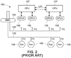
- FIG. 2 schematically depicts the conventional computer system 100 where the GPU 108 is unable to communicate with the BMC 104 by way of the management bus 130.
- the BMC 104 is unable to receive the temperature information of the GPUs 108.
- the BMC is unable to receive the temperature information of the GPUs because some GPUs are not configured to send I 2 C temperature signals to the BMC. Since the GPU cannot pass the temperature information to the BMC 104, the GPUs 108 is unable to effectively control the fan speed of the fans 106. As a result, the GPUs 108 are forced to perform their own assessments to perform slowdowns or shutdowns.
- FIGS. 3A and 3B provide a prior art schematic representation of GPU, BMC, and fan performance where the GPU 108 is untethered to the BMC 104.
- the GPU 108 When the GPU 108 is untethered to the BMC 104, the GPU 108 unable to communicate directly with the BMC 104.
- the BMC 104 In the event the GPU 108 is unable to communicate with the BMC 104, the BMC 104 is forced to rely on its internal temperature sensor, which determines the ambient temperature.
- the GPU 108 can have a predetermined slowdown threshold temperature of 85 degrees Celsius.
- the GPU 108 can also have a predetermined shutdown threshold temperature of 89 degrees Celsius.
- the current temperature of GPU 108 can be 84 degrees Celsius, indicating that the GPU is operating at 97% utilization. In this case, the GPU 108 is approaching the threshold temperature at which the GPU 108 will slow down performance in an attempt to avoid overheating. Furthermore, if the temperature of the GPU 108 should happen to exceed 89 degrees Celsius, the GPU 108 will automatically shut down to prevent any catastrophic damage.
- the BMC 104 only detects an ambient temperature of 32 degrees Celsius. This ambient temperature may or may not be impacted by the temperature of the GPU 108. The BMC 104 will notify the fan 106 to operate at a higher speed only if the ambient temperature exceeds a predetermined threshold. This is independent of the GPU temperature. The fan 106 is operating at 60% merely, while the GPU is approaching the predetermined slowdown threshold temperature of 85 degrees Celsius.
- the current temperature of GPU 108 can be 85 degrees Celsius, indicating that the GPU is operating at 80% utilization.
- the GPU 108 has reached the threshold temperature at which the GPU 108 will slow down performance in an attempt to avoid overheating.
- the BMC 104 only detects an ambient temperature of 33 degrees Celsius. The BMC will notify the fan 106 to operate at a higher speed only if the ambient temperature exceeds a predetermined threshold. This is independent of the temperature of the GPU 108.
- the fan 106 is operating at 60% merely, while the GPU 108 has reached the predetermined slowdown threshold temperature of 85 degrees Celsius. At this point, the GPU is operating at 0% utilization.
- the GPU to be communicatively coupled to the BMC such that the fans can be optimized in response to the GPU temperature.
- the following discussion provides exemplary embodiments of how the BMC can be coupled to the GPU to receive temperature information and other pertinent information relating to the GPU performance.
- FIG. 4 schematically depicts a stack 200 in accordance with certain embodiments of the present disclosure.
- FIG. 4 shows a stack 200, and more specifically a stand-alone, general purpose computer system.
- the computer systems 200 discussed throughout the present disclosure can be of various types, such as desktop computers, laptop computers, tablet computers, handheld computers, server computers, blade servers, industrial computers, appliance controllers, electronics equipment controllers, etc.
- the stack 200 can be a special purpose computer system or a system that incorporates more than one interconnected system, such as a client-server network. Indeed, the stack 200 of FIG. 4 only represents an exemplary embodiment of the present disclosure, and therefore, should not be considered to limit the disclosure in any manner.
- the stack 200 can include a virtual machine 301, a hypervisor 302, a host operating system (OS) 303, and a management controller.
- the management controller can be a physical BMC 304.
- the virtual machine 301 can communicate directly with an electronic component.
- the electronic component can include a GPU 308.
- the electronic component can include any thermally sensitive components known in the art. GPUs are well-known in the art, and therefore not described in further detail herein.
- the GPU 308 dissipates heat while operating. As such, a fan 306 is used to cool off the GPU 308 after the GPU 308 reaches a prescribed temperature.
- the virtual management controller can include a virtual BMC 307.
- the hypervisor 302 also called a virtual machine manager (VMM)
- VMM virtual machine manager
- the virtual BMC 307 is configured to pass messages to a raw BMC buffer 309 at the physical BMC 304. Because the stack 200 has a conventional physical BMC 304, the virtual BMC 307 need not function like a physical BMC 304. However, in some embodiments, the virtual BMC 307 can function like a physical BMC 304.
- the virtual BMC 307 runs as a part of the hypervisor 302 or on a hypervisor that runs on a CPU (not shown).
- the hypervisor 302 can also run on two CPUs, four CPUs, eight CPUs, or any suitable number of CPUs.
- the hypervisor 302 can be of various types and designs, such as XEN, MICROSOFT HYPER-V, VMWARE ESX.
- the operating system 303 can be installed in a virtual machine. In alternative embodiments, the operating system 303 may be running on a physical machine.
- the operating system 303 can host one or more application programs.
- the operating system 303 can host input/output memory management unit peripheral component interconnect express (IOMMU PCIe) devices 315.
- IOMMU PCIe peripheral component interconnect express
- An IOMMU is a memory management unit (MMU) that connects a direct-memory-access-capable (DMA-capable) I/O bus to the main memory. Like a traditional MMU, which translates CPU-visible virtual addresses to physical addresses, and the IOMMU maps device-visible virtual addresses (also called device addresses or I/O addresses in this context) to physical addresses. Some units also provide memory protection from faulty or malicious devices.
- An example IOMMU is the graphics address remapping table (GART) used by AGP and PCIe graphics cards on Intel Architecture and AMD computers.
- the IOMMU PCIe devices 315 are able to communicate through the Virtual Function IO (VFIO) 314 that allows direct access to the IOMMU PCIe devices 315 from user space. Although primarily designed as a hypervisor-bypass technology for virtualization uses, it can also be used in a high performance computing (HPC) context.
- the VFIO 314 allows the IOMMU PCIe devices 315 to communicate through the hypervisor using a quick emulator (QEMU) 313 and a PCIe Passthrough 312.
- the QEMU 313 is a hosted hypervisor that performs hardware virtualization, and the PCIe Passthrough 312 assigns a IOMMU PCIe device 315 (NIC, disk controller, HBA, USB controller, firewire controller, soundcard, etc) to a virtual machine guest, giving it full and direct access to the IOMMU PCIe device 315.
- the IOMMU PCIe devices 315 can communicate directly with the GPU 308.
- the CPU can enable the IOMMU PCIe devices 315 for the VFIO 314 to virtualize the PCIe device.
- the QEMU 313 can be configured to read the user's settings, including the VFIO devices.
- the GPU can be recognized as the Passthrough GPU in the virtual machine. While NVIDIA is an example driver and the low end API for retrieving information from the GPU, other drivers can be implemented to perform the same or similar functions.
- the virtual BMC 307 can be implemented as a part of the hypervisor 302.
- An operating system agent 311 of the stack 200 runs on the virtual machine 301.
- the GPU 308 is able to communicate directly with the operating system agent 311 by way of a CUDA NVML API 310.
- the GPU 308 is in communication with the operating system agent 311, which is also in communication with the virtual BMC 307.
- the operating system agent 311 communicates with the virtual BMC 307 by way of a system interface.
- the system interface can include a keyboard controller style interface.
- the physical BMC 304 can provide advanced monitoring features and more detailed hardware information (such as temperatures in different thermal zones).
- the virtual BMC 307 running on the hypervisor 302 can be communicatively coupled by way of the operating system agent 311 to the GPU 308.
- the virtual BMC 307 can also be communicatively coupled to a GPU temperature sensor (not shown) located at the GPU 308.
- the virtual BMC 307 can also be communicatively coupled by way of the physical BMC 304 to the fan 306. In this way, the virtual BMC 307 can enable the physical BMC 304 to provide monitoring functionality over the temperature sensor and control functionality over the fan 306. This is discussed in more detail with respect to FIGS. 6A and 6B .
- FIG. 5 schematically depicts a stack 300 in accordance with certain embodiments of the present disclosure.
- the stack 300 illustrates multiple GPU devices 308A and 308B in communication with the physical BMC 304.
- the stack 300 can provide a virtual BMCs 307A and 307B for each GPU device (308A and 308B).
- Each of the virtual BMCs 307A and 307B can be connected to the physical BMC 304 by way of a virtual BMC manager 305.
- the virtual BMC manager 305 is implemented to manage the messages received at the physical BMC 304 from the virtual BMCs 307A and 307B.
- the physical BMC 304 can receive the temperature information to control the speed of the BMC fan 306s by reading the NVML API temperature messages.
- the virtual BMC manager 305 also manages authority and access to the physical BMC 304.
- FIGS. 6A and 6B provide a schematic representation of the GPU 308, virtual BMC 307, physical BMC 304, and the fan 306 performance in accordance with an embodiment of the disclosure.
- the physical BMC 304 monitors health-related aspects associated with the stack 200, such as, but not limited to, the temperature of one or more components of the stack 200 (e.g., GPU 308); the speed of rotational components (e.g., spindle motor, fan 306, etc.) within the system; the voltage across or applied to one or more components within the system 200; and the available or used capacity of memory devices within the system 200.
- the temperature of one or more components of the stack 200 e.g., GPU 308
- the speed of rotational components e.g., spindle motor, fan 306, etc.
- the physical BMC 304 is communicatively connected to one or more components by way of the virtual BMC 307 and the virtual BMC manager 305.
- these components include sensor devices for measuring various health, operation, and performance-related parameters within the stack 200.
- the sensor devices may be either hardware or software based components configured or programmed to measure or detect one or more of the various operating and performance-related parameters.
- the physical BMC 304 monitors health, operation, and performance-related parameters received from various components of the stack 200 in order to determine whether an "event" is occurring within the system 200 by way of the virtual BMC 307. For example, with respect to the configuration shown in FIG.
- the physical BMC 304 monitors operation of the GPU 308 by way of the GPU temperature sensor (not shown) to determine whether certain operating or performance related parameters exceed or fall below prescribed threshold ranges of operation.
- An example of such an event may be the temperature reading of heat dissipated by the GPU 308 reaching 84 degrees Celsius.
- the fan 306 is operating at 60%.
- the GPU 108 can have a predetermined slowdown threshold temperature of 85 degrees Celsius and a predetermined shutdown threshold temperature of 89 degrees Celsius. This information can be sent to the physical BMC 304 by way of the virtual BMC 307 and the virtual BMC manager 305.
- the physical BMC 304 may also control one or more components of the computer system 100 in response to the occurrence of an event.
- FIG. 6B illustrates an initiation of the fan 306 in response to the temperature of the GPU 308.
- the physical BMC 304 may initiate operation of the fan 306 upon determining that the temperature dissipated by the GPU 308 is approaching the predetermined slowdown threshold temperature of 85 degrees Celsius. As indicated in FIG. 6A , the fan 306 is operating at 60% fan capacity. In response to the temperature of the GPU 308 approaching the predetermined shutdown threshold temperature of 89 degrees Celsius, the physical BMC 304 may initiate operation of the fan 306 to operate at 75% fan capacity. This is illustrated in FIG. 6B . The increase in fan capacity can cool the GPU 308 to 82 degrees Celsius.
Landscapes
- Engineering & Computer Science (AREA)
- Theoretical Computer Science (AREA)
- Physics & Mathematics (AREA)
- General Physics & Mathematics (AREA)
- General Engineering & Computer Science (AREA)
- Human Computer Interaction (AREA)
- Computing Systems (AREA)
- Quality & Reliability (AREA)
- Software Systems (AREA)
- Manufacturing & Machinery (AREA)
- Automation & Control Theory (AREA)
- Mathematical Physics (AREA)
- Debugging And Monitoring (AREA)
- Cooling Or The Like Of Electrical Apparatus (AREA)
Abstract
Description
- The present invention relates to computer systems and non-transitory computer readable mediums for establishing a virtual a Baseboard Management Controller (BMC) to receive temperature information from individual electronic units within a computing device.
- The various components making up a computer system typically operate within a range of parameters defined by performance protocols or standards. For instance, the temperature within a computer chassis is often monitored to detect when the system may rise above a predetermined temperature reading. Other forms of information that may be monitored within a computer system include, without limitation, voltages associated with semiconductor components located on the baseboard of the system; velocity (e.g., rpm) of cooling fans located on the baseboard or within the system chassis; and the velocity of spindle motors within hard disk drives or optical drives.
- Various types of sensors are being used to detect health, operation, and performance-related parameters associated with a computer system and its constituent components. These sensors include thermostats, voltage meters, and tachometers. A computer system typically employs one or more management modules to assist in the collection and analysis of information sensed by the various sensors measuring operating and performance-related parameters within the system. These management modules may be either software or hardware components, but typically encompass both hardware and software components that are implemented by service processors. One such management module is referred to as a "Baseboard Management Controller" (BMC). The BMC is a microcontroller integrated into the baseboard (also known in the industry as the "motherboard") of a computer system, and having a specified number of contact pins through which information sensed by various sensors is received for analysis by the BMC. In order to perform this analysis, the BMC is programmed with firmware for implementing procedures relating to system monitoring and recovery. With this firmware, the BMC is programmed to monitor various operating and performance-related parameters sensed within a computer system. The BMC is also programmed to analyze this information to determine whether any of the sensed parameters are currently outside of an expected or recommended operating range, the occurrence of which is commonly referred to as an "event."
- In some computer systems, the BMC is unable to communicate directly with the hardware components. In these cases, the hardware components may have an integrated system that detects when its temperature is approaching predetermined threshold levels that would cause lack of performance or catastrophic failure. The integrated system of the hardware components is not connected to a fan system within the computer systems, thereby making the fan system inefficient. Therefore, there is a need to provide a computer system that establishes a connection between the BMC and the hardware components.
- A method of thermal management in a computing device using a management controller is provided. The method includes obtaining, via a virtual management controller, monitoring information of a thermally sensitive component untethered to the management controller. The monitoring information can include temperature information of the thermally sensitive component. The method also includes transmitting, via the virtual management controller, the monitoring information to the management controller via a system interface of the management controller. Finally, the method includes adjusting, via the management controller, the operation of a thermal management component of the computing device tethered to the management controller.
- In some embodiments of the disclosure, the monitoring information for the thermally sensitive component includes identification information. Furthermore, the monitoring information for the thermally sensitive component can include a slowdown temperature, a shutdown temperature, and a current temperature. In some embodiments, the thermally sensitive component can include a graphics processing unit. In addition, a virtual baseboard management controller manager can be implemented to manage messages received at the management controller from two or more virtual management controllers.
- In some embodiments, the management controller can be a baseboard management controller. Furthermore, the thermal management component can be a fan device. In addition, the virtual management controller can be a virtual baseboard management controller.
- A computer system for thermal management of a computing device using a management controller is also provided. The computer system can include a thermally sensitive component, specifically a management controller that includes a system interface. The management controller can be untethered to the thermally sensitive component. The system can also include a thermal management component tethered to the management controller and a virtual management controller. The virtual management controller can be configured to obtain monitoring information of the thermally sensitive component untethered to the management controller. In some embodiments, the monitoring information can include temperature information of the thermally sensitive component. The virtual management controller can also be configured to transmit the monitoring information to the management controller via the system interface of the management controller. Finally, the virtual management controller can be configured to adjust operation of the thermal management component tethered to the management controller.
- A non-transitory computer readable medium that stores instructions executable by at least one processor is also provided. The stored instructions can include obtaining, via a virtual management controller, monitoring information of a thermally sensitive component untethered to the management controller. The monitoring information can include temperature information of the thermally sensitive component. The method also includes transmitting, via the virtual management controller, the monitoring information to the management controller via a system interface of the management controller. Finally, the method includes adjusting, via the management controller, operation of a thermal management component of the computing device tethered to the management controller.
- Additional features and advantages of the disclosure will be set forth in the description that follows, and in part, will be obvious from the description; or can be learned by practice of the principles disclosed herein. The features and advantages of the disclosure can be realized and obtained by means of the instruments and combinations particularly pointed out in the appended claims. These and other features of the disclosure will become fully apparent from the following description and appended claims, or can be learned by the practice of the principles set forth herein.
- In order to describe the manner in which the above-recited disclosure and its advantages and features can be obtained, a more particular description of the principles described above will be rendered by reference to specific examples illustrated in the appended drawings. These drawings depict only example aspects of the disclosure, and are therefore not to be considered as limiting of its scope. These principles are described and explained with additional specificity and detail through the use of the following drawings.
-
FIG. 1 is prior art that schematically depicts a conventional computer system; -
FIG. 2 is prior art that schematically depicts the conventional computer system ofFIG. 1 , where the GPU is unable to communicate with the BMC by way of the management bus; -
FIG. 3A is prior art that is a schematic representation of a GPU, a BMC, and a fan performance where the GPU is unable to communicate directly with the BMC; -
FIG. 3B is prior art that is a schematic representation of a GPU, a BMC, and a fan performance where the GPU is unable to communicate directly with the BMC; -
FIG. 4 schematically depicts astack 200 in accordance with certain embodiments of the present disclosure; -
FIG. 5 schematically depicts astack 300 in accordance with certain embodiments of the present disclosure; -
FIG. 6A provides a schematic representation of a GPU, a virtual BMC, a physical BMC, and a fan performance in accordance with an embodiment of the disclosure; and -
FIG. 6B provides a schematic representation of a GPU, a virtual BMC, a physical BMC, and a fan performance in accordance with an embodiment of the disclosure. - The present invention is described with reference to the attached figures, where like reference numerals are used throughout the figures to designate similar or equivalent elements. The figures are not drawn to scale, and they are provided merely to illustrate the instant invention. Several aspects of the invention are described below with reference to example applications for illustration. It should be understood that numerous specific details, relationships, and methods are set forth to provide a full understanding of the invention. One having ordinary skill in the relevant art, however, will readily recognize that the invention can be practiced without one or more of the specific details, or with other methods. In other instances, well-known structures or operations are not shown in detail to avoid obscuring the invention. The present invention is not limited by the illustrated ordering of acts or events, as some acts may occur in different orders and/or concurrently with other acts or events. Furthermore, not all illustrated acts or events are required to implement a methodology in accordance with the present invention.
- In view of the foregoing, to the present application teaches a method and computer system for thermal management in a computing device using a management controller. The method includes obtaining, via a virtual management controller, monitoring information of a thermally sensitive component untethered to the management controller. The monitoring information can include temperature information of the thermally sensitive component. The method also includes transmitting, via the virtual management controller, the monitoring information to the management controller via a system interface of the management controller. Finally, the method includes adjusting, via the management controller, operation of a thermal management component of the computing device tethered to the management controller.
-
FIG. 1 schematically depicts aconventional computer system 100. Thecomputer system 100 has central processing units (CPU) 107. TheCPUs 107 are standard central processors that perform arithmetic and logical operations necessary for the operation of thecomputer system 100. TheCPUs 107 can be connected to graphic processor units (GPU) 108. Like many electrical components, theGPUs 108 dissipate heat while operating. As such, thecomputer system 100 can providefans 106 to cool off theGPUs 108 after theGPUs 108 reach a prescribed temperature. - Such a determination, i.e., whether the
GPUs 108 exceed a prescribed temperature, is made by a baseboard management controller (BMC) 104. In certain embodiments, theGPUs 108 can be in communication with amanagement bus 130 of thehost computer system 100 to provide information regarding the GPUs' health, operation, and performance conditions to theBMC 104. Such information can include the GPU voltage and temperature. EachGPU 108 can be connected to sensors (not shown) measuring the electrical component's health, operation, and performance-related parameters through, for example, themanagement bus 130. This information can be sent to theBMC 104 by way of themanagement bus 130. TheBMC 104 is also communicatively coupled by way of themanagement bus 130 to thefans 106 to control functionality over thefans 106. - The component that initiates communication on a bus is referred to as a master, and the component to which the communication is sent is referred to as a slave. The
BMC component 104 typically functions as the master on themanagement bus 130, but may also function as either a master or a slave in other circumstances. Each of the various components communicatively connected to theBMC 104 by way of themanagement bus 130 can be addressed using a slave address. Themanagement bus 130 is used by theBMC 104 to request and/or receive various health, operation, and performance-related parameters from one or more components, which can be also communicatively connected to themanagement bus 130. InFIG. 1 , themanagement bus 130 communicatively connects theBMC 104 to the GPUS 108 (and its temperature sensor (not shown)) and theCPU fans 106, thereby providing a means for theBMC 104 to monitor and/or control operation of these components. Themanagement bus 130 can typically include tachometers, heat sensors, voltage meters, amp meters, and digital and analog sensors. In certain embodiments, themanagement bus 130 is an I2C. While thecomputer system 100 exemplifies direct connection between theGPUS 108 and theBMC 104 using the I2C bus, it is important to note that not every available GPU in the industry is able to support transmitting the I2C temperature signal to theBMC 104. -
FIG. 2 schematically depicts theconventional computer system 100 where theGPU 108 is unable to communicate with theBMC 104 by way of themanagement bus 130. In this case, theBMC 104 is unable to receive the temperature information of theGPUs 108. The BMC is unable to receive the temperature information of the GPUs because some GPUs are not configured to send I2C temperature signals to the BMC. Since the GPU cannot pass the temperature information to theBMC 104, theGPUs 108 is unable to effectively control the fan speed of thefans 106. As a result, theGPUs 108 are forced to perform their own assessments to perform slowdowns or shutdowns. -
FIGS. 3A and 3B provide a prior art schematic representation of GPU, BMC, and fan performance where theGPU 108 is untethered to theBMC 104. When theGPU 108 is untethered to theBMC 104, theGPU 108 unable to communicate directly with theBMC 104. In the event theGPU 108 is unable to communicate with theBMC 104, theBMC 104 is forced to rely on its internal temperature sensor, which determines the ambient temperature. InFIG. 3A , theGPU 108 can have a predetermined slowdown threshold temperature of 85 degrees Celsius. TheGPU 108 can also have a predetermined shutdown threshold temperature of 89 degrees Celsius. For the purposes of the example ofFIG. 3A , the current temperature ofGPU 108 can be 84 degrees Celsius, indicating that the GPU is operating at 97% utilization. In this case, theGPU 108 is approaching the threshold temperature at which theGPU 108 will slow down performance in an attempt to avoid overheating. Furthermore, if the temperature of theGPU 108 should happen to exceed 89 degrees Celsius, theGPU 108 will automatically shut down to prevent any catastrophic damage. - It should be noted that the
BMC 104 only detects an ambient temperature of 32 degrees Celsius. This ambient temperature may or may not be impacted by the temperature of theGPU 108. TheBMC 104 will notify thefan 106 to operate at a higher speed only if the ambient temperature exceeds a predetermined threshold. This is independent of the GPU temperature. Thefan 106 is operating at 60% merely, while the GPU is approaching the predetermined slowdown threshold temperature of 85 degrees Celsius. - In
FIG. 3B , the current temperature ofGPU 108 can be 85 degrees Celsius, indicating that the GPU is operating at 80% utilization. In this case, theGPU 108 has reached the threshold temperature at which theGPU 108 will slow down performance in an attempt to avoid overheating. TheBMC 104 only detects an ambient temperature of 33 degrees Celsius. The BMC will notify thefan 106 to operate at a higher speed only if the ambient temperature exceeds a predetermined threshold. This is independent of the temperature of theGPU 108. Thefan 106 is operating at 60% merely, while theGPU 108 has reached the predetermined slowdown threshold temperature of 85 degrees Celsius. At this point, the GPU is operating at 0% utilization. Therefore, there is a need for the GPU to be communicatively coupled to the BMC such that the fans can be optimized in response to the GPU temperature. The following discussion provides exemplary embodiments of how the BMC can be coupled to the GPU to receive temperature information and other pertinent information relating to the GPU performance. -
FIG. 4 schematically depicts astack 200 in accordance with certain embodiments of the present disclosure.FIG. 4 shows astack 200, and more specifically a stand-alone, general purpose computer system. One skilled in the art would appreciate that thecomputer systems 200 discussed throughout the present disclosure can be of various types, such as desktop computers, laptop computers, tablet computers, handheld computers, server computers, blade servers, industrial computers, appliance controllers, electronics equipment controllers, etc. Thestack 200 can be a special purpose computer system or a system that incorporates more than one interconnected system, such as a client-server network. Indeed, thestack 200 ofFIG. 4 only represents an exemplary embodiment of the present disclosure, and therefore, should not be considered to limit the disclosure in any manner. - The
stack 200 can include avirtual machine 301, ahypervisor 302, a host operating system (OS) 303, and a management controller. In some embodiments, the management controller can be aphysical BMC 304. Thevirtual machine 301 can communicate directly with an electronic component. For the purposes of this exemplary embodiment, the electronic component can include aGPU 308. It should be understood by one of ordinary skill in the art that the electronic component can include any thermally sensitive components known in the art. GPUs are well-known in the art, and therefore not described in further detail herein. Like many electrical components, theGPU 308 dissipates heat while operating. As such, afan 306 is used to cool off theGPU 308 after theGPU 308 reaches a prescribed temperature. Such a determination, i.e., whether theGPU 308 exceeds a prescribed temperature, is made by a virtual management controller implemented by utilizing thehypervisor 302. The virtual management controller can include avirtual BMC 307. Thehypervisor 302, also called a virtual machine manager (VMM), is typically one of many hardware virtualization techniques allowing multiple operating systems, termed guests, to run concurrently on a host computer. Thevirtual BMC 307 is configured to pass messages to araw BMC buffer 309 at thephysical BMC 304. Because thestack 200 has a conventionalphysical BMC 304, thevirtual BMC 307 need not function like aphysical BMC 304. However, in some embodiments, thevirtual BMC 307 can function like aphysical BMC 304. - The
virtual BMC 307 runs as a part of thehypervisor 302 or on a hypervisor that runs on a CPU (not shown). One skilled in the art would appreciate that thehypervisor 302 can also run on two CPUs, four CPUs, eight CPUs, or any suitable number of CPUs. Thehypervisor 302 can be of various types and designs, such as XEN, MICROSOFT HYPER-V, VMWARE ESX. In some embodiments, theoperating system 303 can be installed in a virtual machine. In alternative embodiments, theoperating system 303 may be running on a physical machine. Theoperating system 303 can host one or more application programs. For example, theoperating system 303 can host input/output memory management unit peripheral component interconnect express (IOMMU PCIe)devices 315. An IOMMU is a memory management unit (MMU) that connects a direct-memory-access-capable (DMA-capable) I/O bus to the main memory. Like a traditional MMU, which translates CPU-visible virtual addresses to physical addresses, and the IOMMU maps device-visible virtual addresses (also called device addresses or I/O addresses in this context) to physical addresses. Some units also provide memory protection from faulty or malicious devices. An example IOMMU is the graphics address remapping table (GART) used by AGP and PCIe graphics cards on Intel Architecture and AMD computers. - The
IOMMU PCIe devices 315 are able to communicate through the Virtual Function IO (VFIO) 314 that allows direct access to theIOMMU PCIe devices 315 from user space. Although primarily designed as a hypervisor-bypass technology for virtualization uses, it can also be used in a high performance computing (HPC) context. TheVFIO 314 allows theIOMMU PCIe devices 315 to communicate through the hypervisor using a quick emulator (QEMU) 313 and aPCIe Passthrough 312. TheQEMU 313 is a hosted hypervisor that performs hardware virtualization, and thePCIe Passthrough 312 assigns a IOMMU PCIe device 315 (NIC, disk controller, HBA, USB controller, firewire controller, soundcard, etc) to a virtual machine guest, giving it full and direct access to theIOMMU PCIe device 315. Using theQEMU 313 and thePCIe Passthrough 312, theIOMMU PCIe devices 315 can communicate directly with theGPU 308. For example, where the GPU needs virtualization in the virtual machine, the CPU can enable theIOMMU PCIe devices 315 for theVFIO 314 to virtualize the PCIe device. TheQEMU 313 can be configured to read the user's settings, including the VFIO devices. Finally, when the virtual machine loads NVIDIA's driver, the GPU can be recognized as the Passthrough GPU in the virtual machine. While NVIDIA is an example driver and the low end API for retrieving information from the GPU, other drivers can be implemented to perform the same or similar functions. - In certain embodiments, the
virtual BMC 307 can be implemented as a part of thehypervisor 302. Anoperating system agent 311 of thestack 200 runs on thevirtual machine 301. TheGPU 308 is able to communicate directly with theoperating system agent 311 by way of aCUDA NVML API 310. TheGPU 308 is in communication with theoperating system agent 311, which is also in communication with thevirtual BMC 307. Theoperating system agent 311 communicates with thevirtual BMC 307 by way of a system interface. In some embodiments, the system interface can include a keyboard controller style interface. In certain embodiments, thephysical BMC 304 can provide advanced monitoring features and more detailed hardware information (such as temperatures in different thermal zones). - The
virtual BMC 307 running on thehypervisor 302 can be communicatively coupled by way of theoperating system agent 311 to theGPU 308. Thevirtual BMC 307 can also be communicatively coupled to a GPU temperature sensor (not shown) located at theGPU 308. Thevirtual BMC 307 can also be communicatively coupled by way of thephysical BMC 304 to thefan 306. In this way, thevirtual BMC 307 can enable thephysical BMC 304 to provide monitoring functionality over the temperature sensor and control functionality over thefan 306. This is discussed in more detail with respect toFIGS. 6A and 6B . -
FIG. 5 schematically depicts astack 300 in accordance with certain embodiments of the present disclosure. Thestack 300 illustratesmultiple GPU devices physical BMC 304. Thestack 300 can provide avirtual BMCs virtual BMCs physical BMC 304 by way of avirtual BMC manager 305. Thevirtual BMC manager 305 is implemented to manage the messages received at thephysical BMC 304 from thevirtual BMCs virtual BMC manager 305, thephysical BMC 304 can receive the temperature information to control the speed of the BMC fan 306s by reading the NVML API temperature messages. Thevirtual BMC manager 305 also manages authority and access to thephysical BMC 304. -
FIGS. 6A and 6B provide a schematic representation of theGPU 308,virtual BMC 307,physical BMC 304, and thefan 306 performance in accordance with an embodiment of the disclosure. In certain embodiments, thephysical BMC 304 monitors health-related aspects associated with thestack 200, such as, but not limited to, the temperature of one or more components of the stack 200 (e.g., GPU 308); the speed of rotational components (e.g., spindle motor,fan 306, etc.) within the system; the voltage across or applied to one or more components within thesystem 200; and the available or used capacity of memory devices within thesystem 200. - To accomplish these monitoring functions, the
physical BMC 304 is communicatively connected to one or more components by way of thevirtual BMC 307 and thevirtual BMC manager 305. In certain embodiments, these components include sensor devices for measuring various health, operation, and performance-related parameters within thestack 200. The sensor devices may be either hardware or software based components configured or programmed to measure or detect one or more of the various operating and performance-related parameters. Thephysical BMC 304 monitors health, operation, and performance-related parameters received from various components of thestack 200 in order to determine whether an "event" is occurring within thesystem 200 by way of thevirtual BMC 307. For example, with respect to the configuration shown inFIG. 6A , thephysical BMC 304 monitors operation of theGPU 308 by way of the GPU temperature sensor (not shown) to determine whether certain operating or performance related parameters exceed or fall below prescribed threshold ranges of operation. An example of such an event may be the temperature reading of heat dissipated by theGPU 308 reaching 84 degrees Celsius. Thefan 306 is operating at 60%. TheGPU 108 can have a predetermined slowdown threshold temperature of 85 degrees Celsius and a predetermined shutdown threshold temperature of 89 degrees Celsius. This information can be sent to thephysical BMC 304 by way of thevirtual BMC 307 and thevirtual BMC manager 305. - In accordance with certain embodiments of the disclosure, the
physical BMC 304 may also control one or more components of thecomputer system 100 in response to the occurrence of an event. Referring back to the example above,FIG. 6B illustrates an initiation of thefan 306 in response to the temperature of theGPU 308. Thephysical BMC 304 may initiate operation of thefan 306 upon determining that the temperature dissipated by theGPU 308 is approaching the predetermined slowdown threshold temperature of 85 degrees Celsius. As indicated inFIG. 6A , thefan 306 is operating at 60% fan capacity. In response to the temperature of theGPU 308 approaching the predetermined shutdown threshold temperature of 89 degrees Celsius, thephysical BMC 304 may initiate operation of thefan 306 to operate at 75% fan capacity. This is illustrated inFIG. 6B . The increase in fan capacity can cool theGPU 308 to 82 degrees Celsius. - While particular embodiments of the present invention have been shown and described, it will be obvious to those skilled in the relevant arts that changes and modifications may be made without departing from the invention in its broader aspects. Therefore, the aim in the appended claims is to cover all such changes and modifications that fall within the true spirit and scope of the invention. The matter set forth in the foregoing description and accompanying drawings is offered by way of illustration only and not as a limitation. The actual scope of the invention is intended to be defined in the following claims when viewed in their proper perspective based on the prior art.
- The terminology used herein is for the purpose of describing particular embodiments only and is not intended to limit the invention. As used herein, the singular forms "a," "an," and "the" are intended to include the plural forms as well, unless the context clearly indicates otherwise. Furthermore, to the extent that the terms "including," "includes," "having," "has," "with," or variants thereof are used in either the detailed description and/or the claims, such terms are intended to be inclusive in a manner similar to the term "comprising."
- Unless otherwise defined, all terms (including technical and scientific terms) used herein have the same meaning as commonly understood by one of ordinary skill in the art to which this invention belongs. Furthermore, terms, such as those defined in commonly used dictionaries, should be interpreted as having a meaning that is consistent with their meaning in the context of the relevant art, and will not be interpreted in an idealized or overly formal sense unless expressly so defined herein.
Claims (14)
- A method of thermal management in a computing device using a management controller (304), comprising:obtaining, via a virtual management controller (307), monitoring information of one or more thermally sensitive components of the computing device untethered to the management controller (304), the monitoring information comprising temperature information of the one or more thermally sensitive components;transmitting, via the virtual management controller (307), the monitoring information to the management controller (304) via a system interface of the management controller (304); andadjusting, via the management controller, operation of at least one thermal management component of the computing device tethered to the management controller (304).
- The method of claim 1, wherein the monitoring information for each of the one or more thermally sensitive components comprises identification information.
- The method of claims 1 or 2, wherein the monitoring information for each of the one or more thermally sensitive components comprises a slowdown temperature, a shutdown temperature, and a current temperature.
- The method of any of claims 1 to 3, wherein at least one of the one or more thermally sensitive components comprises a graphics processing unit.
- The method of any of claims 1 to 4, further comprising managing, by a virtual baseboard management controller manager, messages received at the management controller from two or more virtual management controllers.
- A computer system (200) for thermal management of a computing device using a management controller (304), wherein the computer system is characterized in that the computer system (200) comprises:one or more thermally sensitive components;a management controller (304) comprising a system interface, wherein the management controller (304) is untethered to the one or more thermally sensitive components;at least one thermal management component tethered to the management controller (304); anda virtual management controller (307) configured to:obtain monitoring information of the one or more thermally sensitive components of the computing device untethered to the management controller (304), the monitoring information comprising temperature information of the one or more thermally sensitive components;transmit the monitoring information to the management controller (304) via the system interface of the management controller (304); andadjust operation of the at least one thermal management component of the computing device tethered to the management controller (304).
- The computer system of claim 6, wherein the monitoring information for each of the one or more thermally sensitive components comprises identification information.
- The computer system of claims 6 or 7, wherein the monitoring information for each of the one or more thermally sensitive components comprises a slowdown temperature, a shutdown temperature, and a current temperature.
- The computer system of any of claims 6 to 8, wherein at least one of the one or more thermally sensitive components comprises a graphics processing unit.
- The computer system of any of claims 6 to 9, further comprising a virtual baseboard management controller manager configured to manage messages received at the management controller from two or more virtual management controllers.
- A non-transitory computer readable medium that stores instructions executable by at least one processor, the instructions comprising:obtaining, via a virtual management controller (307), monitoring information of one or more thermally sensitive components of a computing device untethered to a management controller (304), the monitoring information comprising temperature information of the one or more thermally sensitive components;transmitting, via the virtual management controller (307), the monitoring information to the management controller (304) via a system interface of the management controller (304); andadjusting, via the management controller (304), operation of at least one thermal management component of the computing device tethered to the management controller (304).
- The non-transitory computer readable medium of claim 11, wherein the monitoring information for each of the one or more thermally sensitive components comprises a slowdown temperature, a shutdown temperature, and a current temperature.
- The non-transitory computer readable medium of claims 11 or 12, wherein at least one of the one or more thermally sensitive components comprises a graphics processing unit.
- The non-transitory computer readable medium of any of claims 11 to 13, wherein the management controller is a baseboard management controller, and the virtual management controller is a virtual baseboard management controller.
Applications Claiming Priority (1)
| Application Number | Priority Date | Filing Date | Title |
|---|---|---|---|
| US16/138,319 US10782754B2 (en) | 2018-09-21 | 2018-09-21 | Thermal management via virtual BMC manager |
Publications (2)
| Publication Number | Publication Date |
|---|---|
| EP3627281A1 true EP3627281A1 (en) | 2020-03-25 |
| EP3627281B1 EP3627281B1 (en) | 2025-07-09 |
Family
ID=65013483
Family Applications (1)
| Application Number | Title | Priority Date | Filing Date |
|---|---|---|---|
| EP18215319.7A Active EP3627281B1 (en) | 2018-09-21 | 2018-12-21 | Thermal management via virtual bmc manager |
Country Status (5)
| Country | Link |
|---|---|
| US (1) | US10782754B2 (en) |
| EP (1) | EP3627281B1 (en) |
| JP (1) | JP6735859B2 (en) |
| CN (1) | CN110941524B (en) |
| TW (1) | TWI696064B (en) |
Cited By (1)
| Publication number | Priority date | Publication date | Assignee | Title |
|---|---|---|---|---|
| CN113986466A (en) * | 2021-11-01 | 2022-01-28 | 北京计算机技术及应用研究所 | Cloud computing-oriented GPU virtualization system and method |
Families Citing this family (10)
| Publication number | Priority date | Publication date | Assignee | Title |
|---|---|---|---|---|
| CN118312284A (en) * | 2019-07-31 | 2024-07-09 | 华为技术有限公司 | Virtual machine hot migration method and communication device |
| US11061838B1 (en) * | 2020-01-09 | 2021-07-13 | Dell Products L.P. | System and method for graphics processing unit management infrastructure for real time data collection |
| JP7314845B2 (en) | 2020-03-24 | 2023-07-26 | 株式会社デンソー | motor |
| US20220137969A1 (en) * | 2020-10-29 | 2022-05-05 | Dell Products L.P. | Multi-vendor accelerator management protocol interoperability |
| US12061923B2 (en) * | 2020-12-09 | 2024-08-13 | Mediatek Inc. | Memory protection for virtual machines |
| US20230121562A1 (en) * | 2021-10-15 | 2023-04-20 | Dell Products, L.P. | Telemetry of artificial intelligence (ai) and/or machine learning (ml) workloads |
| US11977505B2 (en) * | 2022-07-29 | 2024-05-07 | Dell Products L.P. | Data center asset client bridging via a passthrough device |
| CN115827517A (en) * | 2022-10-28 | 2023-03-21 | 超聚变数字技术有限公司 | Control method, device and computing device |
| CN116257019B (en) * | 2023-05-15 | 2023-08-04 | 深圳华龙讯达信息技术股份有限公司 | PLC (programmable logic controller) management method and system based on cloud |
| CN117149567A (en) * | 2023-08-30 | 2023-12-01 | 英业达科技有限公司 | Method, device, equipment, medium and product for optimizing heat dissipation regulation of GPU (graphics processing unit) accelerator card |
Citations (3)
| Publication number | Priority date | Publication date | Assignee | Title |
|---|---|---|---|---|
| US20130289926A1 (en) * | 2012-04-30 | 2013-10-31 | American Megatrends, Inc. | Virtual Service Processor Stack |
| US20150355651A1 (en) * | 2014-06-05 | 2015-12-10 | American Megatrends, Inc. | Thermal watchdog process in host computer management and monitoring |
| EP3261420A1 (en) * | 2016-06-16 | 2017-12-27 | Quanta Computer Inc. | Virtual chassis management controller |
Family Cites Families (13)
| Publication number | Priority date | Publication date | Assignee | Title |
|---|---|---|---|---|
| US7360102B2 (en) | 2004-03-29 | 2008-04-15 | Sony Computer Entertainment Inc. | Methods and apparatus for achieving thermal management using processor manipulation |
| US7721120B2 (en) | 2006-09-07 | 2010-05-18 | Hewlett-Packard Development Company, L.P. | Controlling fan speed in electronic system |
| US20100205600A1 (en) * | 2009-02-06 | 2010-08-12 | Inventec Corporation | Simulation method for realizing large batches and different kinds of baseboard management controllers using a single server |
| US8484496B2 (en) | 2011-04-22 | 2013-07-09 | Qualcomm Incorporated | Method and system for thermal management of battery charging concurrencies in a portable computing device |
| US8972759B2 (en) | 2012-06-29 | 2015-03-03 | Qualcomm Incorporated | Adaptive thermal management in a portable computing device including monitoring a temperature signal and holding a performance level during a penalty period |
| US8930519B2 (en) * | 2013-01-08 | 2015-01-06 | American Megatrends, Inc. | Emulated communication between master management instance and assisting management instances on baseboard management controller |
| US9298524B2 (en) * | 2013-03-22 | 2016-03-29 | Insyde Software Corp. | Virtual baseboard management controller |
| WO2015188784A1 (en) | 2014-06-12 | 2015-12-17 | Mediatek Inc. | Thermal management method and electronic system with thermal management mechanism |
| US9915984B2 (en) | 2014-09-11 | 2018-03-13 | Dell Products L.P. | Information handling system heat sink compatibility management |
| US9916270B2 (en) * | 2015-03-27 | 2018-03-13 | Intel Corporation | Virtual intelligent platform management interface (IPMI) satellite controller and method |
| US9785209B2 (en) | 2015-03-31 | 2017-10-10 | Qualcomm Incorporated | Thermal management in a computing device based on workload detection |
| JP6458619B2 (en) | 2015-04-20 | 2019-01-30 | 富士通株式会社 | Electronic device and cooling method thereof |
| WO2019119142A1 (en) * | 2017-12-22 | 2019-06-27 | Mcmaster University | Controlling operational parameters of a cooling unit |
-
2018
- 2018-09-21 US US16/138,319 patent/US10782754B2/en active Active
- 2018-11-13 TW TW107140265A patent/TWI696064B/en active
- 2018-11-28 CN CN201811432677.7A patent/CN110941524B/en active Active
- 2018-12-21 EP EP18215319.7A patent/EP3627281B1/en active Active
-
2019
- 2019-01-16 JP JP2019004915A patent/JP6735859B2/en active Active
Patent Citations (3)
| Publication number | Priority date | Publication date | Assignee | Title |
|---|---|---|---|---|
| US20130289926A1 (en) * | 2012-04-30 | 2013-10-31 | American Megatrends, Inc. | Virtual Service Processor Stack |
| US20150355651A1 (en) * | 2014-06-05 | 2015-12-10 | American Megatrends, Inc. | Thermal watchdog process in host computer management and monitoring |
| EP3261420A1 (en) * | 2016-06-16 | 2017-12-27 | Quanta Computer Inc. | Virtual chassis management controller |
Cited By (1)
| Publication number | Priority date | Publication date | Assignee | Title |
|---|---|---|---|---|
| CN113986466A (en) * | 2021-11-01 | 2022-01-28 | 北京计算机技术及应用研究所 | Cloud computing-oriented GPU virtualization system and method |
Also Published As
| Publication number | Publication date |
|---|---|
| CN110941524B (en) | 2023-08-25 |
| TWI696064B (en) | 2020-06-11 |
| US10782754B2 (en) | 2020-09-22 |
| JP6735859B2 (en) | 2020-08-05 |
| US20200097056A1 (en) | 2020-03-26 |
| CN110941524A (en) | 2020-03-31 |
| JP2020052997A (en) | 2020-04-02 |
| TW202013130A (en) | 2020-04-01 |
| EP3627281B1 (en) | 2025-07-09 |
Similar Documents
| Publication | Publication Date | Title |
|---|---|---|
| EP3627281B1 (en) | Thermal management via virtual bmc manager | |
| US9158564B2 (en) | Virtual service processor stack | |
| US9541971B2 (en) | Multiple level computer system temperature management for cooling fan control | |
| US9507619B2 (en) | Virtualizing a host USB adapter | |
| US20150355651A1 (en) | Thermal watchdog process in host computer management and monitoring | |
| US20140365641A1 (en) | Processor module, server system and method of controlling processor module | |
| US9806959B2 (en) | Baseboard management controller (BMC) to host communication through device independent universal serial bus (USB) interface | |
| CN113312140B (en) | System, storage medium, and method for virtual trusted platform module | |
| US10990436B2 (en) | System and method to handle I/O page faults in an I/O memory management unit | |
| US20190227942A1 (en) | System and Method to Handle I/O Page Faults in an I/O Memory Management Unit | |
| US20200097055A1 (en) | Thermal management via operating system | |
| US10339284B2 (en) | Measurement method, electronic device, and measurement system | |
| US9047112B2 (en) | Installation of virtual service processor to computer system having existing operating system | |
| WO2013024510A2 (en) | Storage control apparatus | |
| US9749189B2 (en) | Generating graphical diagram of physical layout of computer platforms | |
| US8880582B2 (en) | User access to a partitionable server | |
| US8191062B2 (en) | System for processor frequency governors to govern a processor frequency by deriving CPU utilization information based on the state of virtual machine monitor | |
| US8762696B2 (en) | Firmware with a plurality of emulated instances of platform-specific management firmware | |
| CN113391864A (en) | Cloud desktop switching method and system | |
| US10765041B2 (en) | Automatically cooling computer system components for safe servicing | |
| US10298447B2 (en) | System and method for accessing real sensors for virtual service processor stack | |
| CN103902425A (en) | Computer system state monitoring method and device | |
| US10324878B1 (en) | System and method of multiplexing communications | |
| US20230324968A1 (en) | Cooling capability degradation diagnosis in an information handling system | |
| CN113312295B (en) | Computer system, machine-readable storage medium, and method of resetting a computer system |
Legal Events
| Date | Code | Title | Description |
|---|---|---|---|
| PUAI | Public reference made under article 153(3) epc to a published international application that has entered the european phase |
Free format text: ORIGINAL CODE: 0009012 |
|
| STAA | Information on the status of an ep patent application or granted ep patent |
Free format text: STATUS: REQUEST FOR EXAMINATION WAS MADE |
|
| 17P | Request for examination filed |
Effective date: 20190823 |
|
| AK | Designated contracting states |
Kind code of ref document: A1 Designated state(s): AL AT BE BG CH CY CZ DE DK EE ES FI FR GB GR HR HU IE IS IT LI LT LU LV MC MK MT NL NO PL PT RO RS SE SI SK SM TR |
|
| AX | Request for extension of the european patent |
Extension state: BA ME |
|
| STAA | Information on the status of an ep patent application or granted ep patent |
Free format text: STATUS: EXAMINATION IS IN PROGRESS |
|
| 17Q | First examination report despatched |
Effective date: 20210318 |
|
| GRAP | Despatch of communication of intention to grant a patent |
Free format text: ORIGINAL CODE: EPIDOSNIGR1 |
|
| STAA | Information on the status of an ep patent application or granted ep patent |
Free format text: STATUS: GRANT OF PATENT IS INTENDED |
|
| INTG | Intention to grant announced |
Effective date: 20250204 |
|
| P01 | Opt-out of the competence of the unified patent court (upc) registered |
Free format text: CASE NUMBER: APP_11795/2025 Effective date: 20250311 |
|
| GRAS | Grant fee paid |
Free format text: ORIGINAL CODE: EPIDOSNIGR3 |
|
| GRAA | (expected) grant |
Free format text: ORIGINAL CODE: 0009210 |
|
| STAA | Information on the status of an ep patent application or granted ep patent |
Free format text: STATUS: THE PATENT HAS BEEN GRANTED |
|
| AK | Designated contracting states |
Kind code of ref document: B1 Designated state(s): AL AT BE BG CH CY CZ DE DK EE ES FI FR GB GR HR HU IE IS IT LI LT LU LV MC MK MT NL NO PL PT RO RS SE SI SK SM TR |
|
| REG | Reference to a national code |
Ref country code: GB Ref legal event code: FG4D |
|
| REG | Reference to a national code |
Ref country code: CH Ref legal event code: EP |
|
| REG | Reference to a national code |
Ref country code: IE Ref legal event code: FG4D |
|
| REG | Reference to a national code |
Ref country code: DE Ref legal event code: R096 Ref document number: 602018083377 Country of ref document: DE |
|
| REG | Reference to a national code |
Ref country code: NL Ref legal event code: MP Effective date: 20250709 |
|
| PG25 | Lapsed in a contracting state [announced via postgrant information from national office to epo] |
Ref country code: PT Free format text: LAPSE BECAUSE OF FAILURE TO SUBMIT A TRANSLATION OF THE DESCRIPTION OR TO PAY THE FEE WITHIN THE PRESCRIBED TIME-LIMIT Effective date: 20251110 |
|
| PG25 | Lapsed in a contracting state [announced via postgrant information from national office to epo] |
Ref country code: NL Free format text: LAPSE BECAUSE OF FAILURE TO SUBMIT A TRANSLATION OF THE DESCRIPTION OR TO PAY THE FEE WITHIN THE PRESCRIBED TIME-LIMIT Effective date: 20250709 |
|
| REG | Reference to a national code |
Ref country code: AT Ref legal event code: MK05 Ref document number: 1812417 Country of ref document: AT Kind code of ref document: T Effective date: 20250709 |
|
| PG25 | Lapsed in a contracting state [announced via postgrant information from national office to epo] |
Ref country code: IS Free format text: LAPSE BECAUSE OF FAILURE TO SUBMIT A TRANSLATION OF THE DESCRIPTION OR TO PAY THE FEE WITHIN THE PRESCRIBED TIME-LIMIT Effective date: 20251109 |
|
| PGFP | Annual fee paid to national office [announced via postgrant information from national office to epo] |
Ref country code: DE Payment date: 20251028 Year of fee payment: 8 |
|
| PGFP | Annual fee paid to national office [announced via postgrant information from national office to epo] |
Ref country code: GB Payment date: 20251030 Year of fee payment: 8 |
|
| PG25 | Lapsed in a contracting state [announced via postgrant information from national office to epo] |
Ref country code: NO Free format text: LAPSE BECAUSE OF FAILURE TO SUBMIT A TRANSLATION OF THE DESCRIPTION OR TO PAY THE FEE WITHIN THE PRESCRIBED TIME-LIMIT Effective date: 20251009 |
|
| REG | Reference to a national code |
Ref country code: LT Ref legal event code: MG9D |
|
| PG25 | Lapsed in a contracting state [announced via postgrant information from national office to epo] |
Ref country code: AT Free format text: LAPSE BECAUSE OF FAILURE TO SUBMIT A TRANSLATION OF THE DESCRIPTION OR TO PAY THE FEE WITHIN THE PRESCRIBED TIME-LIMIT Effective date: 20250709 |
|
| PG25 | Lapsed in a contracting state [announced via postgrant information from national office to epo] |
Ref country code: FI Free format text: LAPSE BECAUSE OF FAILURE TO SUBMIT A TRANSLATION OF THE DESCRIPTION OR TO PAY THE FEE WITHIN THE PRESCRIBED TIME-LIMIT Effective date: 20250709 |
|
| PG25 | Lapsed in a contracting state [announced via postgrant information from national office to epo] |
Ref country code: HR Free format text: LAPSE BECAUSE OF FAILURE TO SUBMIT A TRANSLATION OF THE DESCRIPTION OR TO PAY THE FEE WITHIN THE PRESCRIBED TIME-LIMIT Effective date: 20250709 |
|
| PGFP | Annual fee paid to national office [announced via postgrant information from national office to epo] |
Ref country code: FR Payment date: 20251023 Year of fee payment: 8 |
|
| PG25 | Lapsed in a contracting state [announced via postgrant information from national office to epo] |
Ref country code: GR Free format text: LAPSE BECAUSE OF FAILURE TO SUBMIT A TRANSLATION OF THE DESCRIPTION OR TO PAY THE FEE WITHIN THE PRESCRIBED TIME-LIMIT Effective date: 20251010 |
|
| PG25 | Lapsed in a contracting state [announced via postgrant information from national office to epo] |
Ref country code: SE Free format text: LAPSE BECAUSE OF FAILURE TO SUBMIT A TRANSLATION OF THE DESCRIPTION OR TO PAY THE FEE WITHIN THE PRESCRIBED TIME-LIMIT Effective date: 20250709 |
|
| PG25 | Lapsed in a contracting state [announced via postgrant information from national office to epo] |
Ref country code: LV Free format text: LAPSE BECAUSE OF FAILURE TO SUBMIT A TRANSLATION OF THE DESCRIPTION OR TO PAY THE FEE WITHIN THE PRESCRIBED TIME-LIMIT Effective date: 20250709 |
|
| PG25 | Lapsed in a contracting state [announced via postgrant information from national office to epo] |
Ref country code: BG Free format text: LAPSE BECAUSE OF FAILURE TO SUBMIT A TRANSLATION OF THE DESCRIPTION OR TO PAY THE FEE WITHIN THE PRESCRIBED TIME-LIMIT Effective date: 20250709 Ref country code: PL Free format text: LAPSE BECAUSE OF FAILURE TO SUBMIT A TRANSLATION OF THE DESCRIPTION OR TO PAY THE FEE WITHIN THE PRESCRIBED TIME-LIMIT Effective date: 20250709 |
|
| PG25 | Lapsed in a contracting state [announced via postgrant information from national office to epo] |
Ref country code: RS Free format text: LAPSE BECAUSE OF FAILURE TO SUBMIT A TRANSLATION OF THE DESCRIPTION OR TO PAY THE FEE WITHIN THE PRESCRIBED TIME-LIMIT Effective date: 20251009 |
|
| PG25 | Lapsed in a contracting state [announced via postgrant information from national office to epo] |
Ref country code: ES Free format text: LAPSE BECAUSE OF FAILURE TO SUBMIT A TRANSLATION OF THE DESCRIPTION OR TO PAY THE FEE WITHIN THE PRESCRIBED TIME-LIMIT Effective date: 20250709 |
|
| PG25 | Lapsed in a contracting state [announced via postgrant information from national office to epo] |
Ref country code: RO Free format text: LAPSE BECAUSE OF FAILURE TO SUBMIT A TRANSLATION OF THE DESCRIPTION OR TO PAY THE FEE WITHIN THE PRESCRIBED TIME-LIMIT Effective date: 20250709 |
|
| PG25 | Lapsed in a contracting state [announced via postgrant information from national office to epo] |
Ref country code: SM Free format text: LAPSE BECAUSE OF FAILURE TO SUBMIT A TRANSLATION OF THE DESCRIPTION OR TO PAY THE FEE WITHIN THE PRESCRIBED TIME-LIMIT Effective date: 20250709 |
|
| PG25 | Lapsed in a contracting state [announced via postgrant information from national office to epo] |
Ref country code: DK Free format text: LAPSE BECAUSE OF FAILURE TO SUBMIT A TRANSLATION OF THE DESCRIPTION OR TO PAY THE FEE WITHIN THE PRESCRIBED TIME-LIMIT Effective date: 20250709 |
|
| PG25 | Lapsed in a contracting state [announced via postgrant information from national office to epo] |
Ref country code: IT Free format text: LAPSE BECAUSE OF FAILURE TO SUBMIT A TRANSLATION OF THE DESCRIPTION OR TO PAY THE FEE WITHIN THE PRESCRIBED TIME-LIMIT Effective date: 20250709 |
|
| PG25 | Lapsed in a contracting state [announced via postgrant information from national office to epo] |
Ref country code: CZ Free format text: LAPSE BECAUSE OF FAILURE TO SUBMIT A TRANSLATION OF THE DESCRIPTION OR TO PAY THE FEE WITHIN THE PRESCRIBED TIME-LIMIT Effective date: 20250709 |
|
| PG25 | Lapsed in a contracting state [announced via postgrant information from national office to epo] |
Ref country code: EE Free format text: LAPSE BECAUSE OF FAILURE TO SUBMIT A TRANSLATION OF THE DESCRIPTION OR TO PAY THE FEE WITHIN THE PRESCRIBED TIME-LIMIT Effective date: 20250709 Ref country code: SK Free format text: LAPSE BECAUSE OF FAILURE TO SUBMIT A TRANSLATION OF THE DESCRIPTION OR TO PAY THE FEE WITHIN THE PRESCRIBED TIME-LIMIT Effective date: 20250709 |
|
| PLBE | No opposition filed within time limit |
Free format text: ORIGINAL CODE: 0009261 |
|
| STAA | Information on the status of an ep patent application or granted ep patent |
Free format text: STATUS: NO OPPOSITION FILED WITHIN TIME LIMIT |