EP3627250A1 - Method and system for free space detection in a cluttered environment - Google Patents
Method and system for free space detection in a cluttered environment Download PDFInfo
- Publication number
- EP3627250A1 EP3627250A1 EP19198719.7A EP19198719A EP3627250A1 EP 3627250 A1 EP3627250 A1 EP 3627250A1 EP 19198719 A EP19198719 A EP 19198719A EP 3627250 A1 EP3627250 A1 EP 3627250A1
- Authority
- EP
- European Patent Office
- Prior art keywords
- unified
- grid map
- occupancy grid
- free space
- segments
- Prior art date
- Legal status (The legal status is an assumption and is not a legal conclusion. Google has not performed a legal analysis and makes no representation as to the accuracy of the status listed.)
- Granted
Links
Images




Classifications
-
- G—PHYSICS
- G05—CONTROLLING; REGULATING
- G05D—SYSTEMS FOR CONTROLLING OR REGULATING NON-ELECTRIC VARIABLES
- G05D1/00—Control of position, course, altitude or attitude of land, water, air or space vehicles, e.g. using automatic pilots
- G05D1/02—Control of position or course in two dimensions
- G05D1/021—Control of position or course in two dimensions specially adapted to land vehicles
- G05D1/0212—Control of position or course in two dimensions specially adapted to land vehicles with means for defining a desired trajectory
- G05D1/0214—Control of position or course in two dimensions specially adapted to land vehicles with means for defining a desired trajectory in accordance with safety or protection criteria, e.g. avoiding hazardous areas
-
- G—PHYSICS
- G05—CONTROLLING; REGULATING
- G05B—CONTROL OR REGULATING SYSTEMS IN GENERAL; FUNCTIONAL ELEMENTS OF SUCH SYSTEMS; MONITORING OR TESTING ARRANGEMENTS FOR SUCH SYSTEMS OR ELEMENTS
- G05B19/00—Program-control systems
- G05B19/02—Program-control systems electric
- G05B19/18—Numerical control [NC], i.e. automatically operating machines, in particular machine tools, e.g. in a manufacturing environment, so as to execute positioning, movement or co-ordinated operations by means of program data in numerical form
- G05B19/406—Numerical control [NC], i.e. automatically operating machines, in particular machine tools, e.g. in a manufacturing environment, so as to execute positioning, movement or co-ordinated operations by means of program data in numerical form characterised by monitoring or safety
- G05B19/4061—Avoiding collision or forbidden zones
-
- G—PHYSICS
- G01—MEASURING; TESTING
- G01C—MEASURING DISTANCES, LEVELS OR BEARINGS; SURVEYING; NAVIGATION; GYROSCOPIC INSTRUMENTS; PHOTOGRAMMETRY OR VIDEOGRAMMETRY
- G01C21/00—Navigation; Navigational instruments not provided for in groups G01C1/00 - G01C19/00
- G01C21/20—Instruments for performing navigational calculations
- G01C21/206—Instruments for performing navigational calculations specially adapted for indoor navigation
-
- G—PHYSICS
- G01—MEASURING; TESTING
- G01C—MEASURING DISTANCES, LEVELS OR BEARINGS; SURVEYING; NAVIGATION; GYROSCOPIC INSTRUMENTS; PHOTOGRAMMETRY OR VIDEOGRAMMETRY
- G01C21/00—Navigation; Navigational instruments not provided for in groups G01C1/00 - G01C19/00
- G01C21/38—Electronic maps specially adapted for navigation; Updating thereof
- G01C21/3863—Structures of map data
- G01C21/3867—Geometry of map features, e.g. shape points, polygons or for simplified maps
-
- G—PHYSICS
- G01—MEASURING; TESTING
- G01C—MEASURING DISTANCES, LEVELS OR BEARINGS; SURVEYING; NAVIGATION; GYROSCOPIC INSTRUMENTS; PHOTOGRAMMETRY OR VIDEOGRAMMETRY
- G01C21/00—Navigation; Navigational instruments not provided for in groups G01C1/00 - G01C19/00
- G01C21/38—Electronic maps specially adapted for navigation; Updating thereof
- G01C21/3863—Structures of map data
- G01C21/387—Organisation of map data, e.g. version management or database structures
- G01C21/3881—Tile-based structures
-
- G—PHYSICS
- G05—CONTROLLING; REGULATING
- G05B—CONTROL OR REGULATING SYSTEMS IN GENERAL; FUNCTIONAL ELEMENTS OF SUCH SYSTEMS; MONITORING OR TESTING ARRANGEMENTS FOR SUCH SYSTEMS OR ELEMENTS
- G05B19/00—Program-control systems
- G05B19/02—Program-control systems electric
- G05B19/418—Total factory control, i.e. centrally controlling a plurality of machines, e.g. direct or distributed numerical control [DNC], flexible manufacturing systems [FMS], integrated manufacturing systems [IMS] or computer integrated manufacturing [CIM]
- G05B19/4189—Total factory control, i.e. centrally controlling a plurality of machines, e.g. direct or distributed numerical control [DNC], flexible manufacturing systems [FMS], integrated manufacturing systems [IMS] or computer integrated manufacturing [CIM] characterised by the transport system
- G05B19/41895—Total factory control, i.e. centrally controlling a plurality of machines, e.g. direct or distributed numerical control [DNC], flexible manufacturing systems [FMS], integrated manufacturing systems [IMS] or computer integrated manufacturing [CIM] characterised by the transport system using automatic guided vehicles [AGV]
-
- G—PHYSICS
- G05—CONTROLLING; REGULATING
- G05D—SYSTEMS FOR CONTROLLING OR REGULATING NON-ELECTRIC VARIABLES
- G05D1/00—Control of position, course, altitude or attitude of land, water, air or space vehicles, e.g. using automatic pilots
- G05D1/0088—Control of position, course, altitude or attitude of land, water, air or space vehicles, e.g. using automatic pilots characterized by the autonomous decision making process, e.g. artificial intelligence, predefined behaviours
-
- G—PHYSICS
- G05—CONTROLLING; REGULATING
- G05D—SYSTEMS FOR CONTROLLING OR REGULATING NON-ELECTRIC VARIABLES
- G05D1/00—Control of position, course, altitude or attitude of land, water, air or space vehicles, e.g. using automatic pilots
- G05D1/02—Control of position or course in two dimensions
- G05D1/021—Control of position or course in two dimensions specially adapted to land vehicles
- G05D1/0268—Control of position or course in two dimensions specially adapted to land vehicles using internal positioning means
- G05D1/0274—Control of position or course in two dimensions specially adapted to land vehicles using internal positioning means using mapping information stored in a memory device
-
- G—PHYSICS
- G05—CONTROLLING; REGULATING
- G05D—SYSTEMS FOR CONTROLLING OR REGULATING NON-ELECTRIC VARIABLES
- G05D1/00—Control of position, course, altitude or attitude of land, water, air or space vehicles, e.g. using automatic pilots
- G05D1/02—Control of position or course in two dimensions
- G05D1/021—Control of position or course in two dimensions specially adapted to land vehicles
- G05D1/0287—Control of position or course in two dimensions specially adapted to land vehicles involving a plurality of land vehicles, e.g. fleet or convoy travelling
- G05D1/0291—Fleet control
-
- G—PHYSICS
- G06—COMPUTING OR CALCULATING; COUNTING
- G06T—IMAGE DATA PROCESSING OR GENERATION, IN GENERAL
- G06T7/00—Image analysis
- G06T7/10—Segmentation; Edge detection
- G06T7/11—Region-based segmentation
-
- G—PHYSICS
- G06—COMPUTING OR CALCULATING; COUNTING
- G06T—IMAGE DATA PROCESSING OR GENERATION, IN GENERAL
- G06T7/00—Image analysis
- G06T7/60—Analysis of geometric attributes
- G06T7/64—Analysis of geometric attributes of convexity or concavity
-
- G—PHYSICS
- G06—COMPUTING OR CALCULATING; COUNTING
- G06V—IMAGE OR VIDEO RECOGNITION OR UNDERSTANDING
- G06V20/00—Scenes; Scene-specific elements
- G06V20/10—Terrestrial scenes
-
- G—PHYSICS
- G05—CONTROLLING; REGULATING
- G05B—CONTROL OR REGULATING SYSTEMS IN GENERAL; FUNCTIONAL ELEMENTS OF SUCH SYSTEMS; MONITORING OR TESTING ARRANGEMENTS FOR SUCH SYSTEMS OR ELEMENTS
- G05B2219/00—Program-control systems
- G05B2219/30—Nc systems
- G05B2219/50—Machine tool, machine tool null till machine tool work handling
- G05B2219/50393—Floor conveyor, AGV automatic guided vehicle
-
- G—PHYSICS
- G06—COMPUTING OR CALCULATING; COUNTING
- G06T—IMAGE DATA PROCESSING OR GENERATION, IN GENERAL
- G06T2210/00—Indexing scheme for image generation or computer graphics
- G06T2210/12—Bounding box
-
- Y—GENERAL TAGGING OF NEW TECHNOLOGICAL DEVELOPMENTS; GENERAL TAGGING OF CROSS-SECTIONAL TECHNOLOGIES SPANNING OVER SEVERAL SECTIONS OF THE IPC; TECHNICAL SUBJECTS COVERED BY FORMER USPC CROSS-REFERENCE ART COLLECTIONS [XRACs] AND DIGESTS
- Y02—TECHNOLOGIES OR APPLICATIONS FOR MITIGATION OR ADAPTATION AGAINST CLIMATE CHANGE
- Y02P—CLIMATE CHANGE MITIGATION TECHNOLOGIES IN THE PRODUCTION OR PROCESSING OF GOODS
- Y02P90/00—Enabling technologies with a potential contribution to greenhouse gas [GHG] emissions mitigation
- Y02P90/02—Total factory control, e.g. smart factories, flexible manufacturing systems [FMS] or integrated manufacturing systems [IMS]
-
- Y—GENERAL TAGGING OF NEW TECHNOLOGICAL DEVELOPMENTS; GENERAL TAGGING OF CROSS-SECTIONAL TECHNOLOGIES SPANNING OVER SEVERAL SECTIONS OF THE IPC; TECHNICAL SUBJECTS COVERED BY FORMER USPC CROSS-REFERENCE ART COLLECTIONS [XRACs] AND DIGESTS
- Y02—TECHNOLOGIES OR APPLICATIONS FOR MITIGATION OR ADAPTATION AGAINST CLIMATE CHANGE
- Y02P—CLIMATE CHANGE MITIGATION TECHNOLOGIES IN THE PRODUCTION OR PROCESSING OF GOODS
- Y02P90/00—Enabling technologies with a potential contribution to greenhouse gas [GHG] emissions mitigation
- Y02P90/60—Electric or hybrid propulsion means for production processes
Definitions
- path planning One such decision making requirement is in terms of path planning.
- robots When robots are deployed in an environment, they may have to move around to perform actions associated with tasks assigned to them. In order to move around, the robots need to perform path planning, during which the robots identify one or more paths (between own location (source) to a destination).
- the path planning is comparatively easy in an open space which is less congested.
- the path planning becomes difficult in a cluttered environment. This is primarily because in a cluttered environment available free space for robotic movement is less as compared to that in a less cluttered environment.
- the convex expansion involves: creating a convex region around each seed; iteratively expanding the convex region within the corresponding unified segment, in all directions, till the edges of the convex region touch either an edge of the unified segment or an edge of the obstacle; and identifying area covered by all the convex regions in the occupancy grid map as the free space.
- the communication interface(s) 103 can include a variety of software and hardware interfaces, for example, a web interface, a graphical user interface, and the like and can facilitate multiple communications within a wide variety of networks N/W and protocol types, including wired networks, for example, LAN, cable, etc., and wireless networks, such as WLAN, cellular, or satellite.
- the communication interface(s) 103 can include one or more ports for connecting a number of devices to one another or to another server.
- the communication interface(s) can be configured to provide one or more channels with appropriate protocols, for the system 100 to communicate with one or more external systems.
- the area covered by the convex regions represent free space in which the area covered in the occupancy grid map, which may be further used for robotic path planning to identify at least one path for the robot to move around.
- the robotic path planning using the free space information may or may not be performed by the system 100.
Landscapes
- Engineering & Computer Science (AREA)
- Radar, Positioning & Navigation (AREA)
- Remote Sensing (AREA)
- Physics & Mathematics (AREA)
- General Physics & Mathematics (AREA)
- Automation & Control Theory (AREA)
- Aviation & Aerospace Engineering (AREA)
- Theoretical Computer Science (AREA)
- Geometry (AREA)
- Computer Vision & Pattern Recognition (AREA)
- Databases & Information Systems (AREA)
- Manufacturing & Machinery (AREA)
- Evolutionary Computation (AREA)
- Business, Economics & Management (AREA)
- Health & Medical Sciences (AREA)
- Artificial Intelligence (AREA)
- Game Theory and Decision Science (AREA)
- Medical Informatics (AREA)
- Multimedia (AREA)
- General Engineering & Computer Science (AREA)
- Human Computer Interaction (AREA)
- Quality & Reliability (AREA)
- Control Of Position, Course, Altitude, Or Attitude Of Moving Bodies (AREA)
Abstract
Description
- The present application claims priority from Indian patent application no.
201821035691 - The disclosure herein generally relates to robotic path planning, and, more particularly, to a method and system for free space detection in a cluttered environment for robotic path planning.
- With advancement in technology, specifically in robotics and automation domains, sophisticated robots are built which are capable of handling different functions/applications. With industrial automation, such robots are replacing manpower. A few examples of domains in which robots are deployed are warehouse management, military operations, change detection, and so on. When robots are deployed for specific applications, traditionally the robots had to be controlled by operators, due to necessity of dynamic decision making to execute certain processes/actions. However Developments in Artificial Intelligence (AI) have given decision making powers to the robots.
- One such decision making requirement is in terms of path planning. When robots are deployed in an environment, they may have to move around to perform actions associated with tasks assigned to them. In order to move around, the robots need to perform path planning, during which the robots identify one or more paths (between own location (source) to a destination). The path planning is comparatively easy in an open space which is less congested. However, the path planning becomes difficult in a cluttered environment. This is primarily because in a cluttered environment available free space for robotic movement is less as compared to that in a less cluttered environment.
- Existing systems for robotic path planning use different approaches for free space identification. For example, most of them use an occupancy grid map to represent an environment in which the robot is present, and locations of objects/obstacles present in that environment are marked in the occupancy grid map. In the occupancy grid map, the area/environment is split into multiple unit geometric grids. The existing systems for path planning mark only those unit geometric grids in which vertices of the object are present, as occupied, even though the object/obstacle maybe completely covering one or more other unit geometric grids (as vertices may not be present in such unit geometric grids), thus producing incorrect data. Another disadvantage of the existing systems is that even though area covered by a unit geometric grid is only partially occupied by an object/obstacle, these systems, by marking such unit geometric grids as occupied, tend to ignore such free space which could have been utilized for robotic movement.
- Embodiments of the present disclosure present technological improvements as solutions to one or more of the above-mentioned technical problems recognized by the inventors in conventional systems. For example, in one embodiment, a processor-implemented method for free space detection for robotic movement is provided. Initially, via one or more hardware processors, sensor data pertaining to location of at least one obstacle in an area being scanned by a robot is fetched. Further, an occupancy grid map of the area is generated based on the sensor data, via the one or more hardware processors, wherein the at least one obstacle is inscribed in a bounding box in the occupancy grid map. Further, all unit geometric grids of the occupancy grid map which are fully or partially inscribed in the bounding box are marked as occupied via the one or more hardware processors. Then the occupancy grid map seeded via the one or more hardware processors, wherein seeding the occupancy grid map involves: generating a plurality of unified segments, wherein each of the plurality of unified segments is generated by merging the unit geometric grids which are out of the at least one bounding box; identifying center of each of the plurality of unified segments; and marking the identified center of each of the plurality of unified segments as a seed of the corresponding unified segment. Further, the free space is identified by executing a convex expansion in the occupancy grid map, via the one or more hardware processors. The convex expansion involves: creating a convex region around each seed; iteratively expanding the convex region within the corresponding unified segment, in all directions, till the edges of the convex region touch either an edge of the unified segment or an edge of the obstacle; and identifying area covered by all the convex regions in the occupancy grid map as the free space.
- In another aspect, a system is provided. The system includes a memory module storing a plurality of instructions; one or more communication interfaces; and one or more hardware processors coupled to the memory module via the one or more communication interfaces. The one or more hardware processors are caused by the plurality of instructions to fetch sensor data pertaining to location of at least one obstacle in an area being scanned by a robot. Further, an occupancy grid map of the area is generated based on the sensor data, wherein the at least one obstacle is inscribed in a bounding box in the occupancy grid map. Further, all unit geometric grids of the occupancy grid map which are fully or partially inscribed in the bounding box are marked as occupied. Then the occupancy grid map seeded, wherein seeding the occupancy grid map involves: generating a plurality of unified segments, wherein each of the plurality of unified segments is generated by merging the unit geometric grids which are out of the at least one bounding box; identifying center of each of the plurality of unified segments; and marking the identified center of each of the plurality of unified segments as a seed of the corresponding unified segment. Further, the free space is identified by executing a convex expansion in the occupancy grid map. The convex expansion involves: creating a convex region around each seed; iteratively expanding the convex region within the corresponding unified segment, in all directions, till the edges of the convex region touch either an edge of the unified segment or an edge of the obstacle; and identifying area covered by all the convex regions in the occupancy grid map as the free space.
- In yet another aspect, a non-transitory computer readable medium for free space detection for robotic movement is provided is provided. The non-transitory computer readable medium performs the free space detection by executing the following steps. Initially, sensor data pertaining to location of at least one obstacle in an area being scanned by a robot is fetched. Further, an occupancy grid map of the area is generated based on the sensor data, wherein the at least one obstacle is inscribed in a bounding box in the occupancy grid map. Further, all unit geometric grids of the occupancy grid map which are fully or partially inscribed in the bounding box are marked as occupied. Then the occupancy grid map seeded, wherein seeding the occupancy grid map involves: generating a plurality of unified segments, wherein each of the plurality of unified segments is generated by merging the unit geometric grids which are out of the at least one bounding box; identifying center of each of the plurality of unified segments; and marking the identified center of each of the plurality of unified segments as a seed of the corresponding unified segment. Further, the free space is identified by executing a convex expansion in the occupancy grid map. The convex expansion involves: creating a convex region around each seed; iteratively expanding the convex region within the corresponding unified segment, in all directions, till the edges of the convex region touch either an edge of the unified segment or an edge of the obstacle; and identifying area covered by all the convex regions in the occupancy grid map as the free space.
- It is to be understood that both the foregoing general description and the following detailed description are exemplary and explanatory only and are not restrictive of the invention, as claimed.
- The accompanying drawings, which are incorporated in and constitute a part of this disclosure, illustrate exemplary embodiments and, together with the description, serve to explain the disclosed principles:
-
FIG. 1 illustrates an exemplary system for free space detection, according to some embodiments of the present disclosure. -
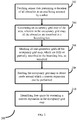
FIG. 2 is a flow diagram depicting steps involved in the process of detecting free space, using the system ofFIG. 1 , according to some embodiments of the present disclosure. -
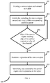
FIG. 3 is a flow diagram depicting steps involved in the process of seeding in an occupancy grid map, using the system ofFIG. 1 , according to some embodiments of the present disclosure. -
FIG. 4 is a flow diagram depicting steps involved in the process of executing a convex expansion in an occupancy grid map, using the system ofFIG. 1 , according to some embodiments of the present disclosure. -
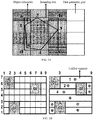
FIGS. 5A, 5B ,5C, 5D , and5E are example diagrams depicting different steps involved in the process of identifying the free space by the system ofFIG. 1 , according to some embodiments of the present disclosure. - Exemplary embodiments are described with reference to the accompanying drawings. In the figures, the left-most digit(s) of a reference number identifies the figure in which the reference number first appears. Wherever convenient, the same reference numbers are used throughout the drawings to refer to the same or like parts. While examples and features of disclosed principles are described herein, modifications, adaptations, and other implementations are possible without departing from the spirit and scope of the disclosed embodiments. It is intended that the following detailed description be considered as exemplary only, with the true scope and spirit being indicated by the following claims.
- Referring now to the drawings, and more particularly to
FIG. 1 through FIG. 5E , where similar reference characters denote corresponding features consistently throughout the figures, there are shown preferred embodiments and these embodiments are described in the context of the following exemplary system and/or method. -
FIG. 1 illustrates an exemplary system for free space detection, according to some embodiments of the present disclosure. Thesystem 100 includes one ormore memory modules 101, one ormore hardware processors 102, and one or more communication interfaces 103. - The memory module(s) 101 may include any computer-readable medium known in the art including, for example, volatile memory, such as static random access memory (SRAM) and dynamic random access memory (DRAM), and/or non-volatile memory, such as read only memory (ROM), erasable programmable ROM, flash memories, hard disks, optical disks, and magnetic tapes. In an embodiment, one or more modules (not shown) of the
system 100 can be stored in thememory 101. The memory module (s) 101 are further configured to store a plurality of instructions, which when executed, cause the one or more hardware processor(s) 102 to perform different actions associated with the free space identification being handled by thesystem 100. The memory module(s) 101 can be further configured to store any data (such as input sensor data, any intermediate output (such as the generated occupancy grid map, seed information and so on), and output (i.e. data pertaining to the free space identified), associated with the free space detection being handled by thesystem 100. - The one or
more hardware processors 102 can be implemented as one or more microprocessors, microcomputers, microcontrollers, digital signal processors, central processing units, state machines, graphics controllers, logic circuitries, and/or any devices that manipulate signals based on operational instructions. Among other capabilities, the processor(s) are configured to fetch and execute computer-readable instructions stored in the memory. In an embodiment, thesystem 100 can be implemented in a variety of computing systems, such as laptop computers, notebooks, hand-held devices, workstations, mainframe computers, servers, a network cloud and the like. The one ormore hardware processors 102 are configured to perform data and control signal processing, at different stages of the free space detection, as required. - The communication interface(s) 103 can include a variety of software and hardware interfaces, for example, a web interface, a graphical user interface, and the like and can facilitate multiple communications within a wide variety of networks N/W and protocol types, including wired networks, for example, LAN, cable, etc., and wireless networks, such as WLAN, cellular, or satellite. In an embodiment, the communication interface(s) 103 can include one or more ports for connecting a number of devices to one another or to another server. The communication interface(s) can be configured to provide one or more channels with appropriate protocols, for the
system 100 to communicate with one or more external systems. For example, the communication interface(s) 103 interacts and collects inputs required for the free space detection, from one or more sensors, wherein the sensors may or may not be part of thesystem 100. The communication interface(s) 103 may further provide appropriate user interface(s) for an authorized user to interact with thesystem 100. The communication interface(s) 103 can be further configured to provide one or more channels for different components of thesystem 100 to interact with each other and perform data and/or control transfer. - The
system 100 can be implemented in different ways. In one mode of implementation, thesystem 100 acts as a stand-alone system that may be hosted on a cloud and/or as part of a network, such that thesystem 100 interacts with one or more robots, collects and processes the sensor data to identify free space in the environments in which the one or more robots are present/located. In another mode of implementation, thesystem 100 can be a dedicated component attached to a robot, which performs the free space identification for that robot. - The
system 100 processes the sensor data from a robot, which is collected as input, and generates an occupancy grid map for the environment (area) being scanned by the robot. In the occupancy grid map, the area being scanned is split to multiple unit geometric grids. One or more physical objects/objects (also referred to as 'obstacles', as the objects act as obstacles while the robot is moving around) may be present in the area being scanned by the robot. While planning a route for the robot to move around, the route is planned such that the robot can avoid collision with these obstacles. While generating the occupancy grid map, thesystem 100 puts a bounding box each, around each object, such that the object is fully inscribed in the bounding box (as depicted inFIG. 5A ). Further, depends on the size of the object and the size of the unit geometric grids, each object may be covering one or more unit geometric grids, partially or completely. Thesystem 100 identifies all the unit geometric grids inscribed in the bounding box, as occupied. Thesystem 100 can be configured to generate a 2 dimensional occupancy grid map and/or a 3 dimensional grid map. Consider the following equations associated with the occupancy grid map generation:


- Generalized form of vertex coordinate in the occupancy grid map is given in equation (1), where


 and
and
 for an N-dimensional bounding box, Bo,N is created inscribing the N dimensional obstacle, o. All the unit geometric grids that are partially or fully inscribed by Bo,N are considered as occupied grids by the obstacle o.
- After generating the occupancy grid map, the
system 100 then seeds the occupancy grid map. At this stage, thesystem 100 analyzes the occupancy grid map and collects data pertaining to unoccupied (free) unit geometric grids i.e. the unit geometric grids which are outside the one or more bounding boxes in the occupancy grid map. Thesystem 100 generates the unified segments by merging multiple free unit geometric grids. Further, thesystem 100 identifies centroid of each unified segment. Further, the identified centroid of each unified segment is marked as seed (or seed point) of the corresponding unified segment (as depicted inFIG. 5C ). Consider the following equations which are associated with the occupancy grid map seeding:


- Here, equation (5) defines an lth unified segment which is a union of free geometric grids. In order to generate the unified segments, the
system 100 considers all free unit geometric grids in any one direction. For example, starting from a free unit geometric grid from left most corner in a row, all other free unit geometric grids in the same row are considered, and they together form a unified segment. Equations (6) and (7) denote U Smin (l) and U Smax (l) which represent collection of minimum position vector

- After seeding and identifying the set of seeds {s}, the system executes a convex expansion on the occupancy grid map. At this step, the
system 100 creates a convex region around each seed i.e. within each unified segment, a convex region is present. Then thesystem 100 iteratively expands the convex regions in each unified segment, simultaneously or one by one. The convex region in a unified segment is expanded such that the convex expansion is terminated when each edge of the convex region touches edge of the unified segment in which it is present or edge of at least one obstacle. After expanding all convex regions in all unified segments of the occupancy grid map (as depicted inFIG. 5E ), the area covered by the convex regions represent free space in which the area covered in the occupancy grid map, which may be further used for robotic path planning to identify at least one path for the robot to move around. The robotic path planning using the free space information may or may not be performed by thesystem 100. -
FIG. 2 is a flow diagram depicting steps involved in the process of detecting free space, using the system ofFIG. 1 , according to some embodiments of the present disclosure. Initially, sensor data pertaining at least to location of all objects/obstacles in an area being scanned by a robot is fetched (202) as input by thesystem 100. Further, using at least the sensor data collected as input, thesystem 100 generates (204) the occupancy grid map in which each of the objects are inscribed in dedicated bounding boxes. Thesystem 100 identifies and marks (206) all the unit geometric grids that are partially or fully inscribed in each bounding box as occupied. Further thesystem 100 seeds (208) the occupancy grid map to identify a set of seeds in the occupancy grid maps, around which a convex expansion can be performed. After identifying the seeds, the system identifies (210) the free space in the occupancy grid map, by executing the convex expansion. In an embodiment, the steps inmethod 200 may be performed in the same order as depicted in the flow diagram or in any alternate order. In another embodiment, one or more steps inmethod 200 may be omitted. -
FIG. 3 is a flow diagram depicting steps involved in the process of seeding in an occupancy grid map, using the system ofFIG. 1 , according to some embodiments of the present disclosure. In this process, thesystem 100 generates one or more unified segments by merging the free unit geometric grids in the occupancy grid map. The free unit geometric grids are the grids in the occupancy grid map, which are not inscribed in any bounding box. This also means that the free unit geometric grids are not occupied by any object/obstacle. After generating the unified segments, thesystem 100 identifies (304) centroid of each of the unified segments. The system further maps (306) the identified centroid of each of the unified segments as the seed of the unified segment. In an embodiment, the steps inmethod 300 may be performed in the same order as depicted in the flow diagram or in any alternate order. In another embodiment, one or more steps inmethod 300 may be omitted. -
FIG. 4 is a flow diagram depicting steps involved in the process of executing a convex expansion in an occupancy grid map, using the system ofFIG. 1 , according to some embodiments of the present disclosure. At this stage, thesystem 100 creates (402) a convex region each, around each seed. Further, each convex region is iteratively expanded (404), and once the edges of the convex region touches edge of the corresponding unified segment or that of the obstacle(s), the convex expansion is terminated (408). In an embodiment, the convex region is expanded over a bounding box, till the convex region touches edges of the obstacle inscribed in the bounding box. After terminating the convex expansion, thesystem 100 identifies (410) area covered by the convex region as the free space. In an embodiment, the steps inmethod 400 may be performed in the same order as depicted in the flow diagram or in any alternate order. In another embodiment, one or more steps inmethod 400 may be omitted. -
FIGS. 5A, 5B ,5C, 5D , and5E are example diagrams depicting different steps involved in the process of identifying the free space by the system ofFIG. 1 , according to some embodiments of the present disclosure. ConsiderFIG. 5A . There are two axes. InFig. 5A there are two axes. One is horizontal i.e., x-axis. The other one is the vertical axis i.e., y-axis. The entire region is divided into 4X 4 grids. The obstacle inFig. 5A has five vertices. Now with reference toFig. 5A , (1)-(3) for and assuming left down corner as the origin:


- The coordinate of d in bounding box abed is


system 100 to generate occupancy grid map in 3-dimension as well. - Now consider
FIG. 5B through FIG. 5D , which depict the seeding of the occupancy grid map depicted inFIG. 5A , followed by a geometric unification. The geometric unification starts from one corner of the occupancy grid map. Let is the start point. InFig. 5B , for the sixth row, first two columns are occupied. In thesixth row column 3 to 8 are free. At this stage thesystem 100 checks for existence of free grid along the sixth row and continue until a new obstacle or boundary appears. Based on that free-region is obtained in the left side ofFig. 5B . Now, fromFig. 5b , and equations (4)-(7):


- Similarly from
Fig 5C and equations (4)-(7):


- In this way, all the unified segments are obtained. After that center of each unified segment is evaluated and is identified as the seed of that region. Further, the
system 100 executes the convex expansion around the identified seeds. The convex expansion on an occupancy grid map is iterated based on number of unified segments (or the number of seeds).


- After that {vo} and {to} are set to an empty set. In the second iteration: (A.2) is kept same.


- This is repeated for all the seeds in the occupancy grid map, and finally the free space available is detected as the area covered by all the (expanded) convex regions in the occupancy grid map.
- The written description describes the subject matter herein to enable any person skilled in the art to make and use the embodiments. The scope of the subject matter embodiments is defined by the claims and may include other modifications that occur to those skilled in the art. Such other modifications are intended to be within the scope of the claims if they have similar elements that do not differ from the literal language of the claims or if they include equivalent elements with insubstantial differences from the literal language of the claims.
- The embodiments of present disclosure herein addresses unresolved problem of free space identification in a cluttered environment for robotic path planning. The embodiment, thus provides a mechanism for free space identification using a combination of seeding and convex expansion in an occupancy grid map generated for an area being scanned by a robot.
- It is to be understood that the scope of the protection is extended to such a program and in addition to a computer-readable means having a message therein; such computer-readable storage means contain program-code means for implementation of one or more steps of the method, when the program runs on a server or mobile device or any suitable programmable device. The hardware device can be any kind of device which can be programmed including e.g. any kind of computer like a server or a personal computer, or the like, or any combination thereof. The device may also include means which could be e.g. hardware means like e.g. an application-specific integrated circuit (ASIC), a field-programmable gate array (FPGA), or a combination of hardware and software means, e.g. an ASIC and an FPGA, or at least one microprocessor and at least one memory with software modules located therein. Thus, the means can include both hardware means and software means. The method embodiments described herein could be implemented in hardware and software. The device may also include software means. Alternatively, the embodiments may be implemented on different hardware devices, e.g. using a plurality of CPUs.
- The embodiments herein can comprise hardware and software elements. The embodiments that are implemented in software include but are not limited to, firmware, resident software, microcode, etc. The functions performed by various modules described herein may be implemented in other modules or combinations of other modules. For the purposes of this description, a computer-usable or computer readable medium can be any apparatus that can comprise, store, communicate, propagate, or transport the program for use by or in connection with the instruction execution system, apparatus, or device.
- The illustrated steps are set out to explain the exemplary embodiments shown, and it should be anticipated that ongoing technological development will change the manner in which particular functions are performed. These examples are presented herein for purposes of illustration, and not limitation. Further, the boundaries of the functional building blocks have been arbitrarily defined herein for the convenience of the description. Alternative boundaries can be defined so long as the specified functions and relationships thereof are appropriately performed. Alternatives (including equivalents, extensions, variations, deviations, etc., of those described herein) will be apparent to persons skilled in the relevant art(s) based on the teachings contained herein. Such alternatives fall within the scope and spirit of the disclosed embodiments. Also, the words "comprising," "having," "containing," and "including," and other similar forms are intended to be equivalent in meaning and be open ended in that an item or items following any one of these words is not meant to be an exhaustive listing of such item or items, or meant to be limited to only the listed item or items. It must also be noted that as used herein and in the appended claims, the singular forms "a," "an," and "the" include plural references unless the context clearly dictates otherwise.
- Furthermore, one or more computer-readable storage media may be utilized in implementing embodiments consistent with the present disclosure. A computer-readable storage medium refers to any type of physical memory on which information or data readable by a processor may be stored. Thus, a computer-readable storage medium may store instructions for execution by one or more processors, including instructions for causing the processor(s) to perform steps or stages consistent with the embodiments described herein. The term "computer-readable medium" should be understood to include tangible items and exclude carrier waves and transient signals, i.e., be non-transitory. Examples include random access memory (RAM), read-only memory (ROM), volatile memory, nonvolatile memory, hard drives, CD ROMs, DVDs, flash drives, disks, and any other known physical storage media.
- It is intended that the disclosure and examples be considered as exemplary only, with a true scope and spirit of disclosed embodiments being indicated by the following claims.
Claims (9)
- A processor-implemented method for free space detection for robotic path planning, comprising:fetching (202), via one or more hardware processors, sensor data pertaining to location of at least one obstacle in an area being scanned by a robot;generating (204) an occupancy grid map of the area based on the sensor data, via the one or more hardware processors, wherein the at least one obstacle is inscribed in a bounding box, in the occupancy grid map;marking (206), via the one or more hardware processors, all unit geometric grids of the occupancy grid map which are fully or partially inscribed in the bounding box, as occupied;seeding (208) the occupancy grid map, via the one or more hardware processors, comprising:generating (302) a plurality of unified segments, wherein each of the plurality of unified segments is generated by merging the unit geometric grids which are out of the at least one bounding box;identifying (304) center of each of the plurality of unified segments; andmarking (306) the identified center of each of the plurality of unified segments as a seed of the corresponding unified segment; andidentifying (210) the free space by executing a convex expansion in the occupancy grid map, via the one or more hardware processors, comprising:creating (402) a convex region around each seed;iteratively (404) expanding the convex region within the corresponding unified segment, in all directions, till the edges of the convex region touch either an edge of the unified segment or an edge of the obstacle; andidentifying (410) area covered by all the convex regions in the occupancy grid map as the free space.
- The method as claimed in claim 1, wherein the plurality of unified segments represent free regions in the occupancy grid map.
- The method as claimed in claim 1, wherein while expanding the convex region in a unified segment, other unified segments are marked as virtual obstacles.
- A system for free space detection for robotic path planning, comprising:a memory module (101) storing a plurality of instructions;one or more communication interfaces (103); andone or more hardware processors (102) coupled to the memory module (101) via the one or more communication interfaces (103), wherein the one or more hardware processors are caused by the plurality of instructions to:fetch sensor data pertaining to location of at least one obstacle in an area being scanned by a robot;generate an occupancy grid map of the area based on the sensor data, wherein the at least one obstacle is inscribed in a bounding box in the occupancy grid map;mark all unit geometric grids of the occupancy grid map which are fully or partially inscribed in the bounding box, as occupied;seed the occupancy grid map, by:generating a plurality of unified segments, wherein each of the plurality of unified segments is generated by merging the unit geometric grids which are out of the at least one bounding box;identifying center of each of the plurality of unified segments; andmarking the identified center of each of the plurality of unified segments as a seed of the corresponding unifiedsegment; andidentify the free space by executing a convex expansion in the occupancy grid map, by:creating a convex region around each seed;iteratively expanding the convex region within the corresponding unified segment, in all directions, till the edges of the convex region touch either an edge of the unified segment or an edge of the obstacle; andidentifying area covered by all the convex regions in the occupancy grid map as the free space.
- The system as claimed in claim 4, wherein the plurality of unified segments represent free regions in the occupancy grid map.
- The system as claimed in claim 4, wherein said system is configured to mark all other unified segments as virtual obstacles while expanding the convex region in a unified segment.
- A non-transitory computer readable medium for free space detection for robotic path planning, comprising one or more instructions, which when executed by one or more hardware processors causes a method for:fetching, via the one or more hardware processors, sensor data pertaining to location of at least one obstacle in an area being scanned by a robot;generating an occupancy grid map of the area based on the sensor data, via the one or more hardware processors, wherein the at least one obstacle is inscribed in a bounding box, in the occupancy grid map;marking, via the one or more hardware processors, all unit geometric grids of the occupancy grid map which are fully or partially inscribed in the bounding box, as occupied;seeding the occupancy grid map, via the one or more hardware processors, comprising:generating a plurality of unified segments, wherein each of the plurality of unified segments is generated by merging the unit geometric grids which are out of the at least one bounding box;identifying center of each of the plurality of unified segments; andmarking the identified center of each of the plurality of unified segments as a seed of the corresponding unified segment; andidentifying the free space by executing a convex expansion in the occupancy grid map, via the one or more hardware processors, comprising:creating a convex region around each seed;iteratively expanding the convex region within the corresponding unified segment, in all directions, till the edges of the convex region touch either an edge of the unified segment or an edge of the obstacle; andidentifying area covered by all the convex regions in the occupancy grid map as the free space.
- The non-transitory computer readable medium as claimed in claim 7, wherein the plurality of unified segments represent free regions in the occupancy grid map.
- The non-transitory computer readable medium as claimed in claim 7, wherein while expanding the convex region in a unified segment, other unified segments are marked as virtual obstacles.
Applications Claiming Priority (1)
| Application Number | Priority Date | Filing Date | Title |
|---|---|---|---|
| IN201821035691 | 2018-09-21 |
Publications (3)
| Publication Number | Publication Date |
|---|---|
| EP3627250A1 true EP3627250A1 (en) | 2020-03-25 |
| EP3627250C0 EP3627250C0 (en) | 2023-12-06 |
| EP3627250B1 EP3627250B1 (en) | 2023-12-06 |
Family
ID=67998374
Family Applications (1)
| Application Number | Title | Priority Date | Filing Date |
|---|---|---|---|
| EP19198719.7A Active EP3627250B1 (en) | 2018-09-21 | 2019-09-20 | Method and system for free space detection in a cluttered environment |
Country Status (2)
| Country | Link |
|---|---|
| US (1) | US11269336B2 (en) |
| EP (1) | EP3627250B1 (en) |
Cited By (6)
| Publication number | Priority date | Publication date | Assignee | Title |
|---|---|---|---|---|
| CN111708361A (en) * | 2020-05-19 | 2020-09-25 | 上海有个机器人有限公司 | Multi-robot collision prediction method and device |
| WO2021227313A1 (en) * | 2020-05-11 | 2021-11-18 | Huawei Technologies Co., Ltd. | Method and system for generating an importance occupancy grid map |
| WO2021238222A1 (en) * | 2020-05-29 | 2021-12-02 | 深圳市银星智能科技股份有限公司 | Obstacle avoidance method for robot, obstacle avoidance device for robot, robot, and storage medium |
| CN114427310A (en) * | 2022-02-18 | 2022-05-03 | 智橙动力(北京)科技有限公司 | Swimming pool edge cleaning method and device, electronic equipment and computer storage medium |
| CN114903384A (en) * | 2022-06-13 | 2022-08-16 | 苏州澜途科技有限公司 | Method and device for segmentation of working scene map area of cleaning robot |
| CN116009589A (en) * | 2023-01-17 | 2023-04-25 | 齐鲁空天信息研究院 | Obstacle avoidance method and system for unmanned aerial vehicles suitable for flying in trenches |
Families Citing this family (11)
| Publication number | Priority date | Publication date | Assignee | Title |
|---|---|---|---|---|
| CN108012326B (en) * | 2017-12-07 | 2019-06-11 | 珠海市一微半导体有限公司 | Method and chip for robot monitoring pet based on grid map |
| US11712802B2 (en) * | 2020-04-20 | 2023-08-01 | Boston Dynamics, Inc. | Construction constrained motion primitives from robot maps |
| CN112526985B (en) * | 2020-10-20 | 2023-04-28 | 深圳银星智能集团股份有限公司 | Walking forbidden zone planning method and device and self-moving robot |
| CN112649011B (en) * | 2020-12-01 | 2022-06-28 | 禾多科技(北京)有限公司 | Vehicle obstacle avoidance method, apparatus, device and computer readable medium |
| CN112561927B (en) * | 2020-12-07 | 2024-03-12 | 深圳市愚公科技有限公司 | Image area dividing method, system, electronic device and storage medium |
| CN112666942A (en) * | 2020-12-15 | 2021-04-16 | 美智纵横科技有限责任公司 | Self-moving robot and path planning method, device, equipment and storage medium thereof |
| CN116380058B (en) * | 2021-12-22 | 2025-07-29 | 珠海一微半导体股份有限公司 | Robot coverage-based grid map operation method, chip and robot |
| KR20240065586A (en) * | 2022-11-03 | 2024-05-14 | 주식회사 트위니 | Multi-traffic control method for plurality of robots performing autonomous driving |
| JP7738616B2 (en) * | 2023-09-29 | 2025-09-12 | 本田技研工業株式会社 | Control device, control method, and program |
| CN117666576B (en) * | 2023-12-01 | 2025-07-04 | 珠海一微半导体股份有限公司 | Recharging control method based on reference guiding direction |
| CN119901273B (en) * | 2024-12-20 | 2025-09-19 | 酷睿程(北京)科技有限公司 | Method, system, device, medium and chip for providing map service |
Citations (2)
| Publication number | Priority date | Publication date | Assignee | Title |
|---|---|---|---|---|
| US20090303234A1 (en) * | 2007-03-15 | 2009-12-10 | Jan-Carsten Becker | Method for object formation |
| US20150081200A1 (en) * | 2013-09-19 | 2015-03-19 | Mitsubishi Electric Research Laboratories, Inc. | Method for Determining Trajectory of Multi-Motor Control System Avoiding Obstacle |
Family Cites Families (11)
| Publication number | Priority date | Publication date | Assignee | Title |
|---|---|---|---|---|
| US6317690B1 (en) * | 1999-06-28 | 2001-11-13 | Min-Chung Gia | Path planning, terrain avoidance and situation awareness system for general aviation |
| KR100748245B1 (en) * | 2005-12-09 | 2007-08-10 | 한국전자통신연구원 | Method for mapping and navigating mobile robot by artificial landmark and local coordinate |
| EP2821875A3 (en) * | 2008-09-03 | 2015-05-20 | Murata Machinery, Ltd. | Route planning method, route planning unit, and autonomous mobile device |
| JP6069923B2 (en) * | 2012-07-20 | 2017-02-01 | セイコーエプソン株式会社 | Robot system, robot, robot controller |
| US11500056B2 (en) * | 2015-07-17 | 2022-11-15 | Origin Wireless, Inc. | Method, apparatus, and system for wireless tracking with graph-based particle filtering |
| CN114675671B (en) | 2014-09-05 | 2025-10-21 | 深圳市大疆创新科技有限公司 | Multi-sensor environment map construction |
| JP6849330B2 (en) * | 2015-08-28 | 2021-03-24 | パナソニック インテレクチュアル プロパティ コーポレーション オブ アメリカPanasonic Intellectual Property Corporation of America | Map generation method, self-position estimation method, robot system, and robot |
| US10962647B2 (en) * | 2016-11-30 | 2021-03-30 | Yujin Robot Co., Ltd. | Lidar apparatus based on time of flight and moving object |
| US11126199B2 (en) * | 2018-04-16 | 2021-09-21 | Baidu Usa Llc | Learning based speed planner for autonomous driving vehicles |
| US20190332114A1 (en) * | 2018-04-26 | 2019-10-31 | Maidbot, Inc. | Robot Contextualization of Map Regions |
| US11911908B2 (en) * | 2018-12-21 | 2024-02-27 | Intrinsic Innovation Llc | Dynamic probabilistic motion planning |
-
2019
- 2019-09-20 EP EP19198719.7A patent/EP3627250B1/en active Active
- 2019-09-20 US US16/578,255 patent/US11269336B2/en active Active
Patent Citations (2)
| Publication number | Priority date | Publication date | Assignee | Title |
|---|---|---|---|---|
| US20090303234A1 (en) * | 2007-03-15 | 2009-12-10 | Jan-Carsten Becker | Method for object formation |
| US20150081200A1 (en) * | 2013-09-19 | 2015-03-19 | Mitsubishi Electric Research Laboratories, Inc. | Method for Determining Trajectory of Multi-Motor Control System Avoiding Obstacle |
Non-Patent Citations (2)
| Title |
|---|
| "Robotics: Modelling, Planning and Control", 23 December 2009, SPRINGER, article BRUNO SICILIANO ET AL: "Robotics: Modelling, Planning and Control - Chapter 12: Motion Planning", pages: 523 - 559, XP055668812 * |
| FABIAN BL\"OCHLIGER ET AL: "Topomap: Topological Mapping and Navigation Based on Visual SLAM Maps", ARXIV.ORG, CORNELL UNIVERSITY LIBRARY, 201 OLIN LIBRARY CORNELL UNIVERSITY ITHACA, NY 14853, 16 September 2017 (2017-09-16), XP081309960 * |
Cited By (8)
| Publication number | Priority date | Publication date | Assignee | Title |
|---|---|---|---|---|
| WO2021227313A1 (en) * | 2020-05-11 | 2021-11-18 | Huawei Technologies Co., Ltd. | Method and system for generating an importance occupancy grid map |
| US11815897B2 (en) | 2020-05-11 | 2023-11-14 | Huawei Technologies Co., Ltd. | Method and system for generating an importance occupancy grid map |
| CN111708361A (en) * | 2020-05-19 | 2020-09-25 | 上海有个机器人有限公司 | Multi-robot collision prediction method and device |
| CN111708361B (en) * | 2020-05-19 | 2023-09-08 | 上海有个机器人有限公司 | Multi-robot collision prediction method and device |
| WO2021238222A1 (en) * | 2020-05-29 | 2021-12-02 | 深圳市银星智能科技股份有限公司 | Obstacle avoidance method for robot, obstacle avoidance device for robot, robot, and storage medium |
| CN114427310A (en) * | 2022-02-18 | 2022-05-03 | 智橙动力(北京)科技有限公司 | Swimming pool edge cleaning method and device, electronic equipment and computer storage medium |
| CN114903384A (en) * | 2022-06-13 | 2022-08-16 | 苏州澜途科技有限公司 | Method and device for segmentation of working scene map area of cleaning robot |
| CN116009589A (en) * | 2023-01-17 | 2023-04-25 | 齐鲁空天信息研究院 | Obstacle avoidance method and system for unmanned aerial vehicles suitable for flying in trenches |
Also Published As
| Publication number | Publication date |
|---|---|
| EP3627250C0 (en) | 2023-12-06 |
| US20200097013A1 (en) | 2020-03-26 |
| EP3627250B1 (en) | 2023-12-06 |
| US11269336B2 (en) | 2022-03-08 |
Similar Documents
| Publication | Publication Date | Title |
|---|---|---|
| EP3627250A1 (en) | Method and system for free space detection in a cluttered environment | |
| EP3742125B1 (en) | Method and system for path planning | |
| US11480974B2 (en) | Topological map generation apparatus for navigation of robot and method thereof | |
| US11292456B2 (en) | Apparatus, method and article to facilitate motion planning of an autonomous vehicle in an environment having dynamic objects | |
| EP3798574B1 (en) | Method and system for real-time path planning | |
| CN106774345B (en) | Method and equipment for multi-robot cooperation | |
| EP3590664B1 (en) | Method and system for hierarchical decomposition of tasks and action planning in a robotic network | |
| US20190022863A1 (en) | Systems and methods for detecting grasp poses for handling target objects | |
| EP3748455A1 (en) | A method and a system for hierarchical network based diverse trajectory proposal | |
| US20200387553A1 (en) | Digitization of technical documentation driven by machine learning | |
| Jaillet et al. | Asymptotically-optimal Path Planning on Manifolds. | |
| US12391244B2 (en) | Method and system for narrow passage path sampling based on levy flight | |
| US20240070900A1 (en) | Method and system for point cloud based grasp planning framework | |
| CN115346041A (en) | Point position marking method, device and equipment based on deep learning and storage medium | |
| CN115014328A (en) | Dynamic loading method, device, equipment and medium for grid map | |
| Ramachandran et al. | A probabilistic approach to automated construction of topological maps using a stochastic robotic swarm | |
| Andreychuk et al. | Applying MAPP Algorithm for Cooperative Path Finding in Urban Environments | |
| Jia et al. | Conflict-based strategy combined integrated optimal conflict avoidance algorithm | |
| Umeo | Linear-time recognition of connectivity of binary images on 1-bit inter-cell communication cellular automaton | |
| JP2001250122A (en) | Object position and orientation determination processing method and program recording medium therefor | |
| CN113171041B (en) | Target path generation method, device, equipment and storage medium | |
| Zhao et al. | CB-GCS: Conflict-based search on the graph of convex sets for multi-agent motion planning | |
| CN112445220A (en) | Control method and device for automatic guided vehicle, storage medium and electronic equipment | |
| US20240126270A1 (en) | Autonomous mobile robot behavioral analysis for deviation warnings | |
| Zhang et al. | A distributed algorithm for the multi-robot minimum time task allocation problem |
Legal Events
| Date | Code | Title | Description |
|---|---|---|---|
| PUAI | Public reference made under article 153(3) epc to a published international application that has entered the european phase |
Free format text: ORIGINAL CODE: 0009012 |
|
| STAA | Information on the status of an ep patent application or granted ep patent |
Free format text: STATUS: THE APPLICATION HAS BEEN PUBLISHED |
|
| AK | Designated contracting states |
Kind code of ref document: A1 Designated state(s): AL AT BE BG CH CY CZ DE DK EE ES FI FR GB GR HR HU IE IS IT LI LT LU LV MC MK MT NL NO PL PT RO RS SE SI SK SM TR |
|
| AX | Request for extension of the european patent |
Extension state: BA ME |
|
| STAA | Information on the status of an ep patent application or granted ep patent |
Free format text: STATUS: REQUEST FOR EXAMINATION WAS MADE |
|
| 17P | Request for examination filed |
Effective date: 20200925 |
|
| RBV | Designated contracting states (corrected) |
Designated state(s): AL AT BE BG CH CY CZ DE DK EE ES FI FR GB GR HR HU IE IS IT LI LT LU LV MC MK MT NL NO PL PT RO RS SE SI SK SM TR |
|
| STAA | Information on the status of an ep patent application or granted ep patent |
Free format text: STATUS: EXAMINATION IS IN PROGRESS |
|
| 17Q | First examination report despatched |
Effective date: 20211117 |
|
| GRAP | Despatch of communication of intention to grant a patent |
Free format text: ORIGINAL CODE: EPIDOSNIGR1 |
|
| STAA | Information on the status of an ep patent application or granted ep patent |
Free format text: STATUS: GRANT OF PATENT IS INTENDED |
|
| RIC1 | Information provided on ipc code assigned before grant |
Ipc: G01C 21/20 20060101ALI20230523BHEP Ipc: G06V 20/10 20220101ALI20230523BHEP Ipc: G01C 21/00 20060101ALI20230523BHEP Ipc: G05D 1/02 20200101ALI20230523BHEP Ipc: G05B 19/418 20060101ALI20230523BHEP Ipc: G05B 19/4061 20060101AFI20230523BHEP |
|
| INTG | Intention to grant announced |
Effective date: 20230619 |
|
| GRAS | Grant fee paid |
Free format text: ORIGINAL CODE: EPIDOSNIGR3 |
|
| GRAA | (expected) grant |
Free format text: ORIGINAL CODE: 0009210 |
|
| STAA | Information on the status of an ep patent application or granted ep patent |
Free format text: STATUS: THE PATENT HAS BEEN GRANTED |
|
| AK | Designated contracting states |
Kind code of ref document: B1 Designated state(s): AL AT BE BG CH CY CZ DE DK EE ES FI FR GB GR HR HU IE IS IT LI LT LU LV MC MK MT NL NO PL PT RO RS SE SI SK SM TR |
|
| REG | Reference to a national code |
Ref country code: GB Ref legal event code: FG4D |
|
| REG | Reference to a national code |
Ref country code: CH Ref legal event code: EP |
|
| REG | Reference to a national code |
Ref country code: DE Ref legal event code: R096 Ref document number: 602019042709 Country of ref document: DE |
|
| REG | Reference to a national code |
Ref country code: IE Ref legal event code: FG4D |
|
| U01 | Request for unitary effect filed |
Effective date: 20240103 |
|
| U07 | Unitary effect registered |
Designated state(s): AT BE BG DE DK EE FI FR IT LT LU LV MT NL PT SE SI Effective date: 20240112 |
|
| PG25 | Lapsed in a contracting state [announced via postgrant information from national office to epo] |
Ref country code: GR Free format text: LAPSE BECAUSE OF FAILURE TO SUBMIT A TRANSLATION OF THE DESCRIPTION OR TO PAY THE FEE WITHIN THE PRESCRIBED TIME-LIMIT Effective date: 20240307 |
|
| PG25 | Lapsed in a contracting state [announced via postgrant information from national office to epo] |
Ref country code: ES Free format text: LAPSE BECAUSE OF FAILURE TO SUBMIT A TRANSLATION OF THE DESCRIPTION OR TO PAY THE FEE WITHIN THE PRESCRIBED TIME-LIMIT Effective date: 20231206 |
|
| PG25 | Lapsed in a contracting state [announced via postgrant information from national office to epo] |
Ref country code: GR Free format text: LAPSE BECAUSE OF FAILURE TO SUBMIT A TRANSLATION OF THE DESCRIPTION OR TO PAY THE FEE WITHIN THE PRESCRIBED TIME-LIMIT Effective date: 20240307 Ref country code: ES Free format text: LAPSE BECAUSE OF FAILURE TO SUBMIT A TRANSLATION OF THE DESCRIPTION OR TO PAY THE FEE WITHIN THE PRESCRIBED TIME-LIMIT Effective date: 20231206 |
|
| PG25 | Lapsed in a contracting state [announced via postgrant information from national office to epo] |
Ref country code: RS Free format text: LAPSE BECAUSE OF FAILURE TO SUBMIT A TRANSLATION OF THE DESCRIPTION OR TO PAY THE FEE WITHIN THE PRESCRIBED TIME-LIMIT Effective date: 20231206 Ref country code: NO Free format text: LAPSE BECAUSE OF FAILURE TO SUBMIT A TRANSLATION OF THE DESCRIPTION OR TO PAY THE FEE WITHIN THE PRESCRIBED TIME-LIMIT Effective date: 20240306 Ref country code: HR Free format text: LAPSE BECAUSE OF FAILURE TO SUBMIT A TRANSLATION OF THE DESCRIPTION OR TO PAY THE FEE WITHIN THE PRESCRIBED TIME-LIMIT Effective date: 20231206 |
|
| PG25 | Lapsed in a contracting state [announced via postgrant information from national office to epo] |
Ref country code: IS Free format text: LAPSE BECAUSE OF FAILURE TO SUBMIT A TRANSLATION OF THE DESCRIPTION OR TO PAY THE FEE WITHIN THE PRESCRIBED TIME-LIMIT Effective date: 20240406 |
|
| PG25 | Lapsed in a contracting state [announced via postgrant information from national office to epo] |
Ref country code: CZ Free format text: LAPSE BECAUSE OF FAILURE TO SUBMIT A TRANSLATION OF THE DESCRIPTION OR TO PAY THE FEE WITHIN THE PRESCRIBED TIME-LIMIT Effective date: 20231206 |
|
| PG25 | Lapsed in a contracting state [announced via postgrant information from national office to epo] |
Ref country code: SK Free format text: LAPSE BECAUSE OF FAILURE TO SUBMIT A TRANSLATION OF THE DESCRIPTION OR TO PAY THE FEE WITHIN THE PRESCRIBED TIME-LIMIT Effective date: 20231206 |
|
| PG25 | Lapsed in a contracting state [announced via postgrant information from national office to epo] |
Ref country code: SM Free format text: LAPSE BECAUSE OF FAILURE TO SUBMIT A TRANSLATION OF THE DESCRIPTION OR TO PAY THE FEE WITHIN THE PRESCRIBED TIME-LIMIT Effective date: 20231206 Ref country code: SK Free format text: LAPSE BECAUSE OF FAILURE TO SUBMIT A TRANSLATION OF THE DESCRIPTION OR TO PAY THE FEE WITHIN THE PRESCRIBED TIME-LIMIT Effective date: 20231206 Ref country code: RO Free format text: LAPSE BECAUSE OF FAILURE TO SUBMIT A TRANSLATION OF THE DESCRIPTION OR TO PAY THE FEE WITHIN THE PRESCRIBED TIME-LIMIT Effective date: 20231206 Ref country code: IS Free format text: LAPSE BECAUSE OF FAILURE TO SUBMIT A TRANSLATION OF THE DESCRIPTION OR TO PAY THE FEE WITHIN THE PRESCRIBED TIME-LIMIT Effective date: 20240406 Ref country code: CZ Free format text: LAPSE BECAUSE OF FAILURE TO SUBMIT A TRANSLATION OF THE DESCRIPTION OR TO PAY THE FEE WITHIN THE PRESCRIBED TIME-LIMIT Effective date: 20231206 |
|
| PG25 | Lapsed in a contracting state [announced via postgrant information from national office to epo] |
Ref country code: PL Free format text: LAPSE BECAUSE OF FAILURE TO SUBMIT A TRANSLATION OF THE DESCRIPTION OR TO PAY THE FEE WITHIN THE PRESCRIBED TIME-LIMIT Effective date: 20231206 |
|
| PG25 | Lapsed in a contracting state [announced via postgrant information from national office to epo] |
Ref country code: PL Free format text: LAPSE BECAUSE OF FAILURE TO SUBMIT A TRANSLATION OF THE DESCRIPTION OR TO PAY THE FEE WITHIN THE PRESCRIBED TIME-LIMIT Effective date: 20231206 |
|
| REG | Reference to a national code |
Ref country code: DE Ref legal event code: R097 Ref document number: 602019042709 Country of ref document: DE |
|
| PLBE | No opposition filed within time limit |
Free format text: ORIGINAL CODE: 0009261 |
|
| STAA | Information on the status of an ep patent application or granted ep patent |
Free format text: STATUS: NO OPPOSITION FILED WITHIN TIME LIMIT |
|
| U20 | Renewal fee for the european patent with unitary effect paid |
Year of fee payment: 6 Effective date: 20240926 |
|
| 26N | No opposition filed |
Effective date: 20240909 |
|
| PG25 | Lapsed in a contracting state [announced via postgrant information from national office to epo] |
Ref country code: MC Free format text: LAPSE BECAUSE OF FAILURE TO SUBMIT A TRANSLATION OF THE DESCRIPTION OR TO PAY THE FEE WITHIN THE PRESCRIBED TIME-LIMIT Effective date: 20231206 |
|
| PG25 | Lapsed in a contracting state [announced via postgrant information from national office to epo] |
Ref country code: IE Free format text: LAPSE BECAUSE OF NON-PAYMENT OF DUE FEES Effective date: 20240920 |
|
| REG | Reference to a national code |
Ref country code: CH Ref legal event code: U11 Free format text: ST27 STATUS EVENT CODE: U-0-0-U10-U11 (AS PROVIDED BY THE NATIONAL OFFICE) Effective date: 20251001 |
|
| PGFP | Annual fee paid to national office [announced via postgrant information from national office to epo] |
Ref country code: GB Payment date: 20250923 Year of fee payment: 7 |
|
| U20 | Renewal fee for the european patent with unitary effect paid |
Year of fee payment: 7 Effective date: 20250925 |
|
| PGFP | Annual fee paid to national office [announced via postgrant information from national office to epo] |
Ref country code: CH Payment date: 20251001 Year of fee payment: 7 |
|
| PG25 | Lapsed in a contracting state [announced via postgrant information from national office to epo] |
Ref country code: CY Free format text: LAPSE BECAUSE OF FAILURE TO SUBMIT A TRANSLATION OF THE DESCRIPTION OR TO PAY THE FEE WITHIN THE PRESCRIBED TIME-LIMIT; INVALID AB INITIO Effective date: 20190920 |
|
| PG25 | Lapsed in a contracting state [announced via postgrant information from national office to epo] |
Ref country code: HU Free format text: LAPSE BECAUSE OF FAILURE TO SUBMIT A TRANSLATION OF THE DESCRIPTION OR TO PAY THE FEE WITHIN THE PRESCRIBED TIME-LIMIT; INVALID AB INITIO Effective date: 20190920 |