EP3627187A1 - Control system for autonomous driving of a vehicle - Google Patents
Control system for autonomous driving of a vehicle Download PDFInfo
- Publication number
- EP3627187A1 EP3627187A1 EP18195247.4A EP18195247A EP3627187A1 EP 3627187 A1 EP3627187 A1 EP 3627187A1 EP 18195247 A EP18195247 A EP 18195247A EP 3627187 A1 EP3627187 A1 EP 3627187A1
- Authority
- EP
- European Patent Office
- Prior art keywords
- vehicle
- sensor device
- attached
- looks
- radar sensor
- Prior art date
- Legal status (The legal status is an assumption and is not a legal conclusion. Google has not performed a legal analysis and makes no representation as to the accuracy of the status listed.)
- Granted
Links
Images


Classifications
-
- G—PHYSICS
- G01—MEASURING; TESTING
- G01S—RADIO DIRECTION-FINDING; RADIO NAVIGATION; DETERMINING DISTANCE OR VELOCITY BY USE OF RADIO WAVES; LOCATING OR PRESENCE-DETECTING BY USE OF THE REFLECTION OR RERADIATION OF RADIO WAVES; ANALOGOUS ARRANGEMENTS USING OTHER WAVES
- G01S13/00—Systems using the reflection or reradiation of radio waves, e.g. radar systems; Analogous systems using reflection or reradiation of waves whose nature or wavelength is irrelevant or unspecified
- G01S13/86—Combinations of radar systems with non-radar systems, e.g. sonar, direction finder
- G01S13/867—Combination of radar systems with cameras
-
- G—PHYSICS
- G01—MEASURING; TESTING
- G01S—RADIO DIRECTION-FINDING; RADIO NAVIGATION; DETERMINING DISTANCE OR VELOCITY BY USE OF RADIO WAVES; LOCATING OR PRESENCE-DETECTING BY USE OF THE REFLECTION OR RERADIATION OF RADIO WAVES; ANALOGOUS ARRANGEMENTS USING OTHER WAVES
- G01S13/00—Systems using the reflection or reradiation of radio waves, e.g. radar systems; Analogous systems using reflection or reradiation of waves whose nature or wavelength is irrelevant or unspecified
- G01S13/86—Combinations of radar systems with non-radar systems, e.g. sonar, direction finder
- G01S13/865—Combination of radar systems with lidar systems
-
- G—PHYSICS
- G01—MEASURING; TESTING
- G01S—RADIO DIRECTION-FINDING; RADIO NAVIGATION; DETERMINING DISTANCE OR VELOCITY BY USE OF RADIO WAVES; LOCATING OR PRESENCE-DETECTING BY USE OF THE REFLECTION OR RERADIATION OF RADIO WAVES; ANALOGOUS ARRANGEMENTS USING OTHER WAVES
- G01S13/00—Systems using the reflection or reradiation of radio waves, e.g. radar systems; Analogous systems using reflection or reradiation of waves whose nature or wavelength is irrelevant or unspecified
- G01S13/87—Combinations of radar systems, e.g. primary radar and secondary radar
-
- G—PHYSICS
- G01—MEASURING; TESTING
- G01S—RADIO DIRECTION-FINDING; RADIO NAVIGATION; DETERMINING DISTANCE OR VELOCITY BY USE OF RADIO WAVES; LOCATING OR PRESENCE-DETECTING BY USE OF THE REFLECTION OR RERADIATION OF RADIO WAVES; ANALOGOUS ARRANGEMENTS USING OTHER WAVES
- G01S13/00—Systems using the reflection or reradiation of radio waves, e.g. radar systems; Analogous systems using reflection or reradiation of waves whose nature or wavelength is irrelevant or unspecified
- G01S13/88—Radar or analogous systems specially adapted for specific applications
- G01S13/93—Radar or analogous systems specially adapted for specific applications for anti-collision purposes
- G01S13/931—Radar or analogous systems specially adapted for specific applications for anti-collision purposes of land vehicles
-
- G—PHYSICS
- G01—MEASURING; TESTING
- G01S—RADIO DIRECTION-FINDING; RADIO NAVIGATION; DETERMINING DISTANCE OR VELOCITY BY USE OF RADIO WAVES; LOCATING OR PRESENCE-DETECTING BY USE OF THE REFLECTION OR RERADIATION OF RADIO WAVES; ANALOGOUS ARRANGEMENTS USING OTHER WAVES
- G01S17/00—Systems using the reflection or reradiation of electromagnetic waves other than radio waves, e.g. lidar systems
- G01S17/87—Combinations of systems using electromagnetic waves other than radio waves
-
- G—PHYSICS
- G01—MEASURING; TESTING
- G01S—RADIO DIRECTION-FINDING; RADIO NAVIGATION; DETERMINING DISTANCE OR VELOCITY BY USE OF RADIO WAVES; LOCATING OR PRESENCE-DETECTING BY USE OF THE REFLECTION OR RERADIATION OF RADIO WAVES; ANALOGOUS ARRANGEMENTS USING OTHER WAVES
- G01S17/00—Systems using the reflection or reradiation of electromagnetic waves other than radio waves, e.g. lidar systems
- G01S17/88—Lidar systems specially adapted for specific applications
- G01S17/93—Lidar systems specially adapted for specific applications for anti-collision purposes
- G01S17/931—Lidar systems specially adapted for specific applications for anti-collision purposes of land vehicles
-
- B—PERFORMING OPERATIONS; TRANSPORTING
- B60—VEHICLES IN GENERAL
- B60W—CONJOINT CONTROL OF VEHICLE SUB-UNITS OF DIFFERENT TYPE OR DIFFERENT FUNCTION; CONTROL SYSTEMS SPECIALLY ADAPTED FOR HYBRID VEHICLES; ROAD VEHICLE DRIVE CONTROL SYSTEMS FOR PURPOSES NOT RELATED TO THE CONTROL OF A PARTICULAR SUB-UNIT
- B60W2300/00—Indexing codes relating to the type of vehicle
- B60W2300/12—Trucks; Load vehicles
-
- B—PERFORMING OPERATIONS; TRANSPORTING
- B60—VEHICLES IN GENERAL
- B60W—CONJOINT CONTROL OF VEHICLE SUB-UNITS OF DIFFERENT TYPE OR DIFFERENT FUNCTION; CONTROL SYSTEMS SPECIALLY ADAPTED FOR HYBRID VEHICLES; ROAD VEHICLE DRIVE CONTROL SYSTEMS FOR PURPOSES NOT RELATED TO THE CONTROL OF A PARTICULAR SUB-UNIT
- B60W2420/00—Indexing codes relating to the type of sensors based on the principle of their operation
- B60W2420/40—Photo, light or radio wave sensitive means, e.g. infrared sensors
- B60W2420/403—Image sensing, e.g. optical camera
-
- B—PERFORMING OPERATIONS; TRANSPORTING
- B60—VEHICLES IN GENERAL
- B60W—CONJOINT CONTROL OF VEHICLE SUB-UNITS OF DIFFERENT TYPE OR DIFFERENT FUNCTION; CONTROL SYSTEMS SPECIALLY ADAPTED FOR HYBRID VEHICLES; ROAD VEHICLE DRIVE CONTROL SYSTEMS FOR PURPOSES NOT RELATED TO THE CONTROL OF A PARTICULAR SUB-UNIT
- B60W2420/00—Indexing codes relating to the type of sensors based on the principle of their operation
- B60W2420/40—Photo, light or radio wave sensitive means, e.g. infrared sensors
- B60W2420/408—Radar; Laser, e.g. lidar
-
- B—PERFORMING OPERATIONS; TRANSPORTING
- B60—VEHICLES IN GENERAL
- B60W—CONJOINT CONTROL OF VEHICLE SUB-UNITS OF DIFFERENT TYPE OR DIFFERENT FUNCTION; CONTROL SYSTEMS SPECIALLY ADAPTED FOR HYBRID VEHICLES; ROAD VEHICLE DRIVE CONTROL SYSTEMS FOR PURPOSES NOT RELATED TO THE CONTROL OF A PARTICULAR SUB-UNIT
- B60W30/00—Purposes of road vehicle drive control systems not related to the control of a particular sub-unit, e.g. of systems using conjoint control of vehicle sub-units
- B60W30/08—Active safety systems predicting or avoiding probable or impending collision or attempting to minimise its consequences
- B60W30/09—Taking automatic action to avoid collision, e.g. braking and steering
-
- G—PHYSICS
- G01—MEASURING; TESTING
- G01S—RADIO DIRECTION-FINDING; RADIO NAVIGATION; DETERMINING DISTANCE OR VELOCITY BY USE OF RADIO WAVES; LOCATING OR PRESENCE-DETECTING BY USE OF THE REFLECTION OR RERADIATION OF RADIO WAVES; ANALOGOUS ARRANGEMENTS USING OTHER WAVES
- G01S13/00—Systems using the reflection or reradiation of radio waves, e.g. radar systems; Analogous systems using reflection or reradiation of waves whose nature or wavelength is irrelevant or unspecified
- G01S13/88—Radar or analogous systems specially adapted for specific applications
- G01S13/93—Radar or analogous systems specially adapted for specific applications for anti-collision purposes
- G01S13/931—Radar or analogous systems specially adapted for specific applications for anti-collision purposes of land vehicles
- G01S2013/9327—Sensor installation details
- G01S2013/93271—Sensor installation details in the front of the vehicles
-
- G—PHYSICS
- G01—MEASURING; TESTING
- G01S—RADIO DIRECTION-FINDING; RADIO NAVIGATION; DETERMINING DISTANCE OR VELOCITY BY USE OF RADIO WAVES; LOCATING OR PRESENCE-DETECTING BY USE OF THE REFLECTION OR RERADIATION OF RADIO WAVES; ANALOGOUS ARRANGEMENTS USING OTHER WAVES
- G01S13/00—Systems using the reflection or reradiation of radio waves, e.g. radar systems; Analogous systems using reflection or reradiation of waves whose nature or wavelength is irrelevant or unspecified
- G01S13/88—Radar or analogous systems specially adapted for specific applications
- G01S13/93—Radar or analogous systems specially adapted for specific applications for anti-collision purposes
- G01S13/931—Radar or analogous systems specially adapted for specific applications for anti-collision purposes of land vehicles
- G01S2013/9327—Sensor installation details
- G01S2013/93272—Sensor installation details in the back of the vehicles
-
- G—PHYSICS
- G01—MEASURING; TESTING
- G01S—RADIO DIRECTION-FINDING; RADIO NAVIGATION; DETERMINING DISTANCE OR VELOCITY BY USE OF RADIO WAVES; LOCATING OR PRESENCE-DETECTING BY USE OF THE REFLECTION OR RERADIATION OF RADIO WAVES; ANALOGOUS ARRANGEMENTS USING OTHER WAVES
- G01S13/00—Systems using the reflection or reradiation of radio waves, e.g. radar systems; Analogous systems using reflection or reradiation of waves whose nature or wavelength is irrelevant or unspecified
- G01S13/88—Radar or analogous systems specially adapted for specific applications
- G01S13/93—Radar or analogous systems specially adapted for specific applications for anti-collision purposes
- G01S13/931—Radar or analogous systems specially adapted for specific applications for anti-collision purposes of land vehicles
- G01S2013/9327—Sensor installation details
- G01S2013/93273—Sensor installation details on the top of the vehicles
-
- G—PHYSICS
- G01—MEASURING; TESTING
- G01S—RADIO DIRECTION-FINDING; RADIO NAVIGATION; DETERMINING DISTANCE OR VELOCITY BY USE OF RADIO WAVES; LOCATING OR PRESENCE-DETECTING BY USE OF THE REFLECTION OR RERADIATION OF RADIO WAVES; ANALOGOUS ARRANGEMENTS USING OTHER WAVES
- G01S13/00—Systems using the reflection or reradiation of radio waves, e.g. radar systems; Analogous systems using reflection or reradiation of waves whose nature or wavelength is irrelevant or unspecified
- G01S13/88—Radar or analogous systems specially adapted for specific applications
- G01S13/93—Radar or analogous systems specially adapted for specific applications for anti-collision purposes
- G01S13/931—Radar or analogous systems specially adapted for specific applications for anti-collision purposes of land vehicles
- G01S2013/9327—Sensor installation details
- G01S2013/93274—Sensor installation details on the side of the vehicles
Definitions
- the invention relates to a control system for autonomous driving of a vehicle, in particular to a control system for autonomous driving of a transport vehicle, as e.g. a truck and trailer combination.
- the object underlying the invention is to enable a more secure safe-operation of autonomously driving vehicle.
- a control system for autonomous driving of a vehicle comprises a first radar sensor device attached at a front side of the vehicle such that it looks forward, a second radar sensor device attached at the front side of the vehicle such that it looks forward, a third radar sensor device attached at a first lateral side of the vehicle such that it looks sideward, a fourth radar sensor device attached at a second lateral side of the vehicle such that it looks sideward, a fifth radar sensor device attached at the first lateral side of the vehicle such that it looks rearward, a sixths radar sensor device attached the second lateral side of the vehicle such that it looks rearward, a first camera sensor device attached at the front side of the vehicle such that it looks forward, a second camera sensor device attached at the front side of the vehicle such that it looks forward, a third camera sensor device attached at the first lateral side of the vehicle such that it looks rearward, and a fourth camera sensor device attached at the second lateral side of the vehicle such that it looks rearward, wherein the first radar sensor device and the second radar sensor device
- a redundant environment sensor architecture as a part of a redundant hardware architecture that can fulfil the requirement to carry out minimal risk safety manoeuvre even after a partial malfunction is provided.
- main and backup circuits are differentiated with their own power supply sources, and appropriate sensors are doubled into redundant pairs.
- the third radar sensor device is attached at a lateral driver side of the vehicle such that it looks sideward, at least two fourth radar sensor devices attached at a lateral co-driver side of the vehicle such that they look sideward are provided, the fifth radar sensor device is attached at the lateral driver side of the vehicle such that it looks rearward, and at least two sixth radar sensor devices attached at the lateral co-driver side of the vehicle such that they look rearward are provided, wherein at least one of the at least two fourth radar sensor devices is configured to be supplied by a battery circuit independent from the battery circuit of another one of the at least two fourth radar sensor devices such as to be redundant devices, and at least one of the at least two sixths radar sensor devices is configured to be supplied by a battery circuit independent from the battery circuit of another one of the at least two sixths radar sensor devices such as to be redundant devices.
- this control system is able to provide an in-lane minimal risk manoeuvre or co-driver side direction lane change minimal risk manoeuver in most of the cases.
- control system further comprises a first fisheye lens camera sensor device attached at a first front corner of the vehicle such that it looks downward, and a second fisheye lens camera sensor device attached at a second front corner of the vehicle such that it looks downward.
- the third camera sensor device is attached at the lateral driver side of the vehicle such that it looks rearward, and at least two fourth camera sensor devices attached at the lateral co-driver side of the vehicle such that they look rearward are provided
- the first fisheye lens camera sensor device is attached at a driver side front corner of the vehicle such that it looks downward
- at least two second fisheye lens camera sensor devices attached at a co-driver side front corner of the vehicle such that they look downward are provided
- at least one of the at least two fourth camera sensor devices is configured to be supplied by a battery circuit independent from the battery circuit of another one of the at least two fourth camera sensor devices such as to be redundant devices
- at least one of the at least two second fisheye lens camera sensor devices is configured to be supplied by a battery circuit independent from the battery circuit of another one of the at least two second fisheye lens camera sensor devices such as to be redundant devices.
- control system further comprises a first rotational Lidar sensor device attached at the first lateral side of the vehicle and a second rotational Lidar sensor device attached at the second lateral side of the vehicle, wherein the first rotational Lidar sensor device and the second rotational Lidar sensor device are respectively configured to look sideward and forward.
- control system further comprises three solid state Lidar sensor devices, respectively one solid state Lidar device being attached at the first lateral side, at the front side of the vehicle, and at the second lateral side.
- control system further comprises a seventh radar sensor device attached at the vehicle such that it looks rearward below the vehicle.
- control system further comprises an ultrasonic sensor device attached at a front side of the vehicle such that it looks forward.
- control system further comprises an eighth radar sensor device and a ninth radar sensor device both being attached to the front side of the vehicle such that they look forward at a wide angle.
- control system is configured to use object information detected by the sensor devices to decelerate or to stop the vehicle, or to execute a lane change with the vehicle, when an object is detected in a specific field of view of the sensor devices.
- Fig. 1 shows a first embodiment of a vehicle 1 including a control system 2 according to the invention.
- the vehicle 1 is a tractor of a trailer truck, however, any appropriate vehicle can be equipped with the control system 2.
- the control system 2 is provided with a redundant environment sensor architecture as a part of a redundant hardware architecture. Based on this idea, main circuits including main sensor devices and backup circuits, which are less sophisticated circuits, including backup sensor devices are differentiated.
- the main sensors provide data that enable the vehicle to drive in an autonomous manner.
- the backup sensors provide data enabling the vehicle 1 to perform a safety manoeuver and, therefore, the vehicle 1 can perform a necessary safety manoeuver if either circuit fails.
- the control system 2 comprises a first radar sensor device 3 attached at a front side of the vehicle 1 such that it looks forward (FLR), a third radar sensor device 4 attached at a first lateral side of the vehicle 1 such that it looks sideward (SLR) and a fourth radar sensor device 4' attached at a second lateral side of the vehicle 1 such that it looks sideward (SLR), a fifth radar sensor device 5 attached at the first lateral side of the vehicle 1 such that it looks rearward (RLR) and a sixth radar sensor device 5' (RLR) attached at the second lateral side of the vehicle 1 such that it looks rearward, a first camera sensor device 6 attached at the front side of the vehicle 1 such that it looks forward (FLC), a third camera sensor device 7 attached at the first lateral side of the vehicle 1 such that it looks rearward (RLC), and a fourth camera sensor device 7' attached the second lateral side of the vehicle 1 such that it looks rearward (RLC).
- FLR front side of the vehicle 1
- SLR sideward
- SLR sideward
- control system 2 comprises a second radar sensor device 3' attached at the front side of the vehicle such that it looks forward (FLR), and a second camera sensor device 6' attached at the front side of the vehicle 1 such that it looks forward (FLC).
- FLR forward
- FLC forward
- the first radar sensor device 3 (FLR) and the second radar sensor device 3' (FLR) are configured to be supplied by battery circuits independent from each other such as to be redundant devices, and the first camera sensor device 6 (FLC) and the second camera sensor device 6' (FLC) are configured to be supplied by battery circuits independent from each other such as to be redundant devices.
- control system 2 comprises a first fisheye lens camera sensor device 8 (DCC) attached at a first front corner of the vehicle 1 such that it looks downward and a second fisheye lens camera sensor device 8' (DCC) attached at a second front corner of the vehicle 1 such that it looks downward.
- DCC fisheye lens camera sensor device 8
- DCC fisheye lens camera sensor device 8'
- the control system 2 is not provided with the fisheye lens camera sensors 8, 8' or the camera devices are not provided with fisheye lenses but with another suitable sensor.
- control system 2 comprises a first rotational Lidar sensor device 9 (FLL) attached at the first lateral side of the vehicle 1 and a second rotational Lidar sensor device 9' (FLL) attached at the second lateral side of the vehicle 1.
- the rotational Lidar sensor devices 9, 9' can respectively be replaced by three solid state Lidar sensor devices, respectively being placed at the first lateral side, at the front side of the vehicle, and at the second lateral side.
- the Lidar sensor devices can be omitted.
- control system 2 is provided with a seventh radar sensor device 10 attached at the vehicle such that it looks rearward below the vehicle.
- the control system 2 is also provided with an ultrasonic sensor device 11 attached at a front side of the vehicle 1 such that it looks forward and with an eights radar sensor device 12 attached to the front side of the vehicle such that it looks forward at a wide angle.
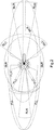
- Fig. 2 shows fields of view of the sensor devices of the control system of Fig. 1 .
- a narrow field FLR (Forward Looking Radar) indicates a fields of view of the first and second radar sensor devices (far field Forward Looking Radar sensor devices) 3, 3' and a broad field FLR indicates a field of view of the eights radar sensor device (wide angle Forward Looking Radar sensor device) 12 for in lane objects detection especially in bad weather conditions.
- Fields SLR (Side Looking Radar) indicate fields of view of the third and fourth radar sensor devices (wide angle Side Looking Radar sensor devices) 4, 4' at each side of the vehicle 1 for monitoring and object detection in the neighbouring lanes in the close proximity of the vehicle 1.
- Two fields FLC indicate fields of view of the first and second camera sensor devices (far field Forward Looking Camera sensor devices) 6, 6' for detection of lane markings, in lane objects, peer-vehicle detection in surrounding lanes, traffic signs, and road infrastructure elements.
- the forward looking camera sensor device 6' merely detects lane marking and in lane objects.
- Two fields RLC (Rear Looking Camera) indicate fields of view of the third and fourth camera sensor devices (far field Rear Looking Camera sensor devices) 7, 7' for monitoring and object detection in neighbouring lanes in the far field of the vehicle 1.
- Two fields DCC (Downward looking Corner Camera) indicate fields of view of the first and second fist eye lens camera sensor device (Downward looking Corner Camera sensor device) 8, 8' for monitoring and object detection in the direct proximity of the vehicle not covered by the front and rear far field sensor fields FLC, FLR, RLC and RLR.
- Field MLR (Mid Lower Radar) indicates a field of view of the seventh radar sensor device (Mid Lower Radar sensor device) 10 for coverage of rear field of the vehicle 1 and looking underfloor of the vehicle 1.
- Fields FLL (Far Field Lidar) indicate fields of view of the first and second rotational Lidar sensor devices 9, 9' for monitoring objects in near proximity at both sides of the vehicle 1, detecting hazardous objects in near proximity with high confidence, and providing a 3 D representation of the surrounding environments.
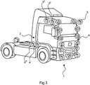
- Fig. 3 shows the vehicle 1 including a second embodiment of the control system 2.
- the control system 2 of this embodiment has the same main sensors as the embodiment shown in Fig. 1 and Fig. 2 .
- third radar sensor device wide angle Side Looking Radar sensor device 4 (SLR) is provided at the lateral driver side and, additionally to the embodiment shown in Fig. 1 and Fig. 2 , at the co-driver side, the fourth radar sensor device (wide angle Side Looking Radar sensor device) 4' (SLR) is doubled to a further wide angle Side Looking Radar sensor device 4" (+SLR).
- the fifth radar sensor device far field Rear Looking Radar sensor device 5 (RLR) is provided and, at the co-driver side, the sixth radar sensor device (far field Rear Looking Radar sensor device) 5' (RLR) is doubled to a further far field Rear Looking Radar sensor device 5" (+RLR).
- This provides backup sensor devices for proving an in-lane minimal risk manoeuver or a co-driver side direction lane change minimal risk manoeuver in most of the cases.
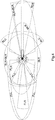
- Fig. 4 shows fields of view of the sensor devices of the control system 2 of Fig. 3 .
- Fig. 4 except from the fields of view FLR, FLL, FLC, SLR, DCC, RLC, MLR and RLR already depicted in Fig. 2 , additional fields of view "+SLR” and "+RLR” are provided by the redundant sensor devices 4" and 5".
- Fig. 5 shows the vehicle 1 including a third embodiment of the control system 2.
- the control system 2 of this embodiment has the same main sensors as the embodiment shown in Fig. 3 and Fig. 4 .
- the third camera sensor device (far field rear looking camera sensor device) 7 (RLC) and the first fisheye lens camera sensor device) downward looking corner camera sensor device 8 (DCC) are provided at the lateral driver side of the vehicle 1 and, additionally to the sensor devices 4", 5" of the second embodiment shown in Fig. 3 and Fig.
- the fourth camera sensor device (far field rear looking camera sensor device) 7' (RLC) and the optional second fisheye lens camera sensor device (downward looking corner camera sensor device) 8' (DCC) are doubled to a further far field rear looking camera sensor device 7" (+RLC) and a further downward looking corner camera sensor device 8" (+DCC) as being provided as backup sensor devices for proving an in-lane minimal risk manoeuver or a co-driver side direction lane change minimal risk manoeuver in all cases.
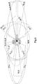
- Fig. 6 shows fields of view of the sensor devices of the control system of Fig. 5 .
- the present sensor devices capture vehicular environment scene data.
- the main sensor devices provide first vehicular scene data to a first processing unit for determining first vehicular control data on the basis of the first vehicular scene data for enabling the vehicle to drive in an autonomous manner.
- the backup sensor devices provide second vehicular scene data to a second processing unit for determining second vehicular control data on the basis of the second vehicular scene data to perform a safety manoeuver.
Landscapes
- Engineering & Computer Science (AREA)
- Radar, Positioning & Navigation (AREA)
- Remote Sensing (AREA)
- Physics & Mathematics (AREA)
- Computer Networks & Wireless Communication (AREA)
- General Physics & Mathematics (AREA)
- Electromagnetism (AREA)
- Traffic Control Systems (AREA)
- Radar Systems Or Details Thereof (AREA)
Abstract
Description
- The invention relates to a control system for autonomous driving of a vehicle, in particular to a control system for autonomous driving of a transport vehicle, as e.g. a truck and trailer combination.
- The autonomous operation of transport vehicles is a new field of inventions. Highly sophisticated functions require high-end hardware infrastructure including different types of sensors and perception technologies. Until now, SAE Automation
level 2 systems require presence and attention of a driver. SAEAutomation level 3 systems should manage autonomous driving without continuous attention of the driver. In this case, an incident may occur when an element of the system malfunctions or becomes offline. - Until now, in particular in the field of commercial vehicles and trucks, no safe solution or consideration which is able to handle such a situation and which is able to carry out minimal risk safety manoeuvre even after a partial malfunction has been known.
- Therefore, the object underlying the invention is to enable a more secure safe-operation of autonomously driving vehicle.
- The object is achieved by a control system according to
claim 1. Advantageous further developments are included in the dependent claims. - According to an aspect of the invention, a control system for autonomous driving of a vehicle comprises a first radar sensor device attached at a front side of the vehicle such that it looks forward, a second radar sensor device attached at the front side of the vehicle such that it looks forward, a third radar sensor device attached at a first lateral side of the vehicle such that it looks sideward, a fourth radar sensor device attached at a second lateral side of the vehicle such that it looks sideward, a fifth radar sensor device attached at the first lateral side of the vehicle such that it looks rearward, a sixths radar sensor device attached the second lateral side of the vehicle such that it looks rearward, a first camera sensor device attached at the front side of the vehicle such that it looks forward, a second camera sensor device attached at the front side of the vehicle such that it looks forward, a third camera sensor device attached at the first lateral side of the vehicle such that it looks rearward, and a fourth camera sensor device attached at the second lateral side of the vehicle such that it looks rearward, wherein the first radar sensor device and the second radar sensor device are configured to be supplied by battery circuits independent from each other such as to be redundant devices, and the first camera sensor device and the second camera sensor device are configured to be supplied by battery circuits independent from each other such as to be redundant devices.
- By such a configuration of the control system, wherein several sensors simultaneously observe a same direction of the vehicle, a redundant environment sensor architecture as a part of a redundant hardware architecture that can fulfil the requirement to carry out minimal risk safety manoeuvre even after a partial malfunction is provided. Based on this idea, main and backup circuits are differentiated with their own power supply sources, and appropriate sensors are doubled into redundant pairs.
- In an advantageous implementation of the control system, the third radar sensor device is attached at a lateral driver side of the vehicle such that it looks sideward, at least two fourth radar sensor devices attached at a lateral co-driver side of the vehicle such that they look sideward are provided, the fifth radar sensor device is attached at the lateral driver side of the vehicle such that it looks rearward, and at least two sixth radar sensor devices attached at the lateral co-driver side of the vehicle such that they look rearward are provided, wherein at least one of the at least two fourth radar sensor devices is configured to be supplied by a battery circuit independent from the battery circuit of another one of the at least two fourth radar sensor devices such as to be redundant devices, and at least one of the at least two sixths radar sensor devices is configured to be supplied by a battery circuit independent from the battery circuit of another one of the at least two sixths radar sensor devices such as to be redundant devices.
- Compared to the control system according the aspect of the invention, this control system is able to provide an in-lane minimal risk manoeuvre or co-driver side direction lane change minimal risk manoeuver in most of the cases.
- In an advantageous implementation of the control system, the control system further comprises a first fisheye lens camera sensor device attached at a first front corner of the vehicle such that it looks downward, and a second fisheye lens camera sensor device attached at a second front corner of the vehicle such that it looks downward.
- By providing these camera sensor devices, monitoring and object detection in a direct proximity of the vehicle not covered by front or rear far field sensors is possible.
- In an advantageous implementation of the control system, the third camera sensor device is attached at the lateral driver side of the vehicle such that it looks rearward, and at least two fourth camera sensor devices attached at the lateral co-driver side of the vehicle such that they look rearward are provided, the first fisheye lens camera sensor device is attached at a driver side front corner of the vehicle such that it looks downward, and at least two second fisheye lens camera sensor devices attached at a co-driver side front corner of the vehicle such that they look downward are provided, wherein at least one of the at least two fourth camera sensor devices is configured to be supplied by a battery circuit independent from the battery circuit of another one of the at least two fourth camera sensor devices such as to be redundant devices, and at least one of the at least two second fisheye lens camera sensor devices is configured to be supplied by a battery circuit independent from the battery circuit of another one of the at least two second fisheye lens camera sensor devices such as to be redundant devices.
- Du to this configuration, proving an in-lane minimal risk manoeuver or a co-driver side direction lane change minimal risk manoeuver in all cases is possible.
- In a further advantageous implementation of the control system, it further comprises a first rotational Lidar sensor device attached at the first lateral side of the vehicle and a second rotational Lidar sensor device attached at the second lateral side of the vehicle, wherein the first rotational Lidar sensor device and the second rotational Lidar sensor device are respectively configured to look sideward and forward.
- By these wide angle rotational Lidar sensor devices, in particular at each frontal side of the vehicle, monitoring objects in close proximity at both sides and at the front side, detecting a hazardous object in close proximity with high confidence, and providing a 3 D representation of the surrounding environments are possible.
- In another advantageous implementation of the control system, it further comprises three solid state Lidar sensor devices, respectively one solid state Lidar device being attached at the first lateral side, at the front side of the vehicle, and at the second lateral side.
- Due to this configuration, monitoring objects in close proximity at both sides and at the front side, detecting a hazardous object in close proximity with high confidence, and providing a 3 D representation of the surrounding environments are also possible.
- In a further advantageous implementation of the control system, it further comprises a seventh radar sensor device attached at the vehicle such that it looks rearward below the vehicle.
- Because of the provision of this radar sensor device, also the portion of environments directly behind the vehicle can be monitored.
- In a further advantageous implementation of the control system, it further comprises an ultrasonic sensor device attached at a front side of the vehicle such that it looks forward.
- When providing this ultrasonic sensor device, near field object proximity detection is possible.
- In a further advantageous implementation of the control system, it further comprises an eighth radar sensor device and a ninth radar sensor device both being attached to the front side of the vehicle such that they look forward at a wide angle.
- By providing these wide angle forward looking radar, detection in a wide field in front of the vehicle is possible especially in bad weather conditions.
- In a further advantageous implementation of the control system, the control system is configured to use object information detected by the sensor devices to decelerate or to stop the vehicle, or to execute a lane change with the vehicle, when an object is detected in a specific field of view of the sensor devices.
- By this use, autonomous driving of a vehicle even in hazardous situations, is possible.
- In the following, the invention is elucidated by means of embodiments referring to the attached drawings.
- In particular,
- Fig. 1
- shows a vehicle including a first embodiment of a control system according to the invention;
- Fig. 2
- shows fields of view of sensor devices of the control system of
Fig. 1 ; - Fig. 3
- shows the vehicle including a second embodiment of the control system;
- Fig. 4
- shows fields of view of the sensor devices of the control system of
Fig. 3 ; - Fig. 5
- shows the vehicle including a third embodiment of the control system; and
- Fig. 6
- shows fields of view of the sensor devices of the control system of
Fig. 5 . -
Fig. 1 shows a first embodiment of avehicle 1 including acontrol system 2 according to the invention. In this embodiment, thevehicle 1 is a tractor of a trailer truck, however, any appropriate vehicle can be equipped with thecontrol system 2. - The
control system 2 is provided with a redundant environment sensor architecture as a part of a redundant hardware architecture. Based on this idea, main circuits including main sensor devices and backup circuits, which are less sophisticated circuits, including backup sensor devices are differentiated. The main sensors provide data that enable the vehicle to drive in an autonomous manner. The backup sensors provide data enabling thevehicle 1 to perform a safety manoeuver and, therefore, thevehicle 1 can perform a necessary safety manoeuver if either circuit fails. - As the main sensors, the
control system 2 comprises a firstradar sensor device 3 attached at a front side of thevehicle 1 such that it looks forward (FLR), a thirdradar sensor device 4 attached at a first lateral side of thevehicle 1 such that it looks sideward (SLR) and a fourth radar sensor device 4' attached at a second lateral side of thevehicle 1 such that it looks sideward (SLR), a fifthradar sensor device 5 attached at the first lateral side of thevehicle 1 such that it looks rearward (RLR) and a sixth radar sensor device 5' (RLR) attached at the second lateral side of thevehicle 1 such that it looks rearward, a first camera sensor device 6 attached at the front side of thevehicle 1 such that it looks forward (FLC), a thirdcamera sensor device 7 attached at the first lateral side of thevehicle 1 such that it looks rearward (RLC), and a fourth camera sensor device 7' attached the second lateral side of thevehicle 1 such that it looks rearward (RLC). - Moreover, as backup sensors, the
control system 2 comprises a second radar sensor device 3' attached at the front side of the vehicle such that it looks forward (FLR), and a second camera sensor device 6' attached at the front side of thevehicle 1 such that it looks forward (FLC). - The first radar sensor device 3 (FLR) and the second radar sensor device 3' (FLR) are configured to be supplied by battery circuits independent from each other such as to be redundant devices, and the first camera sensor device 6 (FLC) and the second camera sensor device 6' (FLC) are configured to be supplied by battery circuits independent from each other such as to be redundant devices.
- Further, the
control system 2 comprises a first fisheye lens camera sensor device 8 (DCC) attached at a first front corner of thevehicle 1 such that it looks downward and a second fisheye lens camera sensor device 8' (DCC) attached at a second front corner of thevehicle 1 such that it looks downward. In alternative embodiments, thecontrol system 2 is not provided with the fisheyelens camera sensors 8, 8' or the camera devices are not provided with fisheye lenses but with another suitable sensor. - Furthermore, the
control system 2 comprises a first rotational Lidar sensor device 9 (FLL) attached at the first lateral side of thevehicle 1 and a second rotational Lidar sensor device 9' (FLL) attached at the second lateral side of thevehicle 1. In alternative embodiments, the rotationalLidar sensor devices 9, 9' can respectively be replaced by three solid state Lidar sensor devices, respectively being placed at the first lateral side, at the front side of the vehicle, and at the second lateral side. In further alternative embodiments, the Lidar sensor devices can be omitted. - Moreover, the
control system 2 is provided with a seventhradar sensor device 10 attached at the vehicle such that it looks rearward below the vehicle. - The
control system 2 is also provided with anultrasonic sensor device 11 attached at a front side of thevehicle 1 such that it looks forward and with an eightsradar sensor device 12 attached to the front side of the vehicle such that it looks forward at a wide angle. -
Fig. 2 shows fields of view of the sensor devices of the control system ofFig. 1 . - A narrow field FLR (Forward Looking Radar) indicates a fields of view of the first and second radar sensor devices (far field Forward Looking Radar sensor devices) 3, 3' and a broad field FLR indicates a field of view of the eights radar sensor device (wide angle Forward Looking Radar sensor device) 12 for in lane objects detection especially in bad weather conditions.
- Fields SLR (Side Looking Radar) indicate fields of view of the third and fourth radar sensor devices (wide angle Side Looking Radar sensor devices) 4, 4' at each side of the
vehicle 1 for monitoring and object detection in the neighbouring lanes in the close proximity of thevehicle 1. - Two narrow fields RLR (Rear Looking Radar) indicate fields of view of the fifth and sixth radar sensor devices (far field Rear Looking Radar sensor devices) 5, 5' for monitoring and object detection in the neighbouring lanes in the far field of the
vehicle 1, especially in bad weather conditions. - Two fields FLC (Forward Looking Camera) indicate fields of view of the first and second camera sensor devices (far field Forward Looking Camera sensor devices) 6, 6' for detection of lane markings, in lane objects, peer-vehicle detection in surrounding lanes, traffic signs, and road infrastructure elements. The forward looking camera sensor device 6' merely detects lane marking and in lane objects.
- Two fields RLC (Rear Looking Camera) indicate fields of view of the third and fourth camera sensor devices (far field Rear Looking Camera sensor devices) 7, 7' for monitoring and object detection in neighbouring lanes in the far field of the
vehicle 1. - Two fields DCC (Downward looking Corner Camera) indicate fields of view of the first and second fist eye lens camera sensor device (Downward looking Corner Camera sensor device) 8, 8' for monitoring and object detection in the direct proximity of the vehicle not covered by the front and rear far field sensor fields FLC, FLR, RLC and RLR.
- Field MLR (Mid Lower Radar) indicates a field of view of the seventh radar sensor device (Mid Lower Radar sensor device) 10 for coverage of rear field of the
vehicle 1 and looking underfloor of thevehicle 1. - Fields FLL (Far Field Lidar) indicate fields of view of the first and second rotational
Lidar sensor devices 9, 9' for monitoring objects in near proximity at both sides of thevehicle 1, detecting hazardous objects in near proximity with high confidence, and providing a 3 D representation of the surrounding environments. -
Fig. 3 shows thevehicle 1 including a second embodiment of thecontrol system 2. - The
control system 2 of this embodiment has the same main sensors as the embodiment shown inFig. 1 andFig. 2 . In a backup sensor cluster, third radar sensor device (wide angle Side Looking Radar sensor device) 4 (SLR) is provided at the lateral driver side and, additionally to the embodiment shown inFig. 1 andFig. 2 , at the co-driver side, the fourth radar sensor device (wide angle Side Looking Radar sensor device) 4' (SLR) is doubled to a further wide angle Side LookingRadar sensor device 4" (+SLR). At the lateral driver side, the fifth radar sensor device (far field Rear Looking Radar sensor device) 5 (RLR) is provided and, at the co-driver side, the sixth radar sensor device (far field Rear Looking Radar sensor device) 5' (RLR) is doubled to a further far field Rear LookingRadar sensor device 5" (+RLR). This provides backup sensor devices for proving an in-lane minimal risk manoeuver or a co-driver side direction lane change minimal risk manoeuver in most of the cases. -
Fig. 4 shows fields of view of the sensor devices of thecontrol system 2 ofFig. 3 . In theFig. 4 , except from the fields of view FLR, FLL, FLC, SLR, DCC, RLC, MLR and RLR already depicted inFig. 2 , additional fields of view "+SLR" and "+RLR" are provided by theredundant sensor devices 4" and 5". -
Fig. 5 shows thevehicle 1 including a third embodiment of thecontrol system 2. - The
control system 2 of this embodiment has the same main sensors as the embodiment shown inFig. 3 andFig. 4 . In a backup sensor cluster, the third camera sensor device (far field rear looking camera sensor device) 7 (RLC) and the first fisheye lens camera sensor device) downward looking corner camera sensor device 8 (DCC) are provided at the lateral driver side of thevehicle 1 and, additionally to thesensor devices 4", 5" of the second embodiment shown inFig. 3 andFig. 4 , on the co-driver side, the fourth camera sensor device (far field rear looking camera sensor device) 7' (RLC) and the optional second fisheye lens camera sensor device (downward looking corner camera sensor device) 8' (DCC) are doubled to a further far field rear lookingcamera sensor device 7" (+RLC) and a further downward looking cornercamera sensor device 8" (+DCC) as being provided as backup sensor devices for proving an in-lane minimal risk manoeuver or a co-driver side direction lane change minimal risk manoeuver in all cases. -
Fig. 6 shows fields of view of the sensor devices of the control system ofFig. 5 . - In the
Fig. 6 , except from the fields of view FLR, FLL, FLC, SLR, DCC, RLC, MLR and RLR and the additional fields of view "+SLR" and "+RLR" of the second embodiment shown inFig. 4 , additional fields "+RLC" and "+DCC" are provided by theredundant sensor devices 4" and 8". - In use, the present sensor devices capture vehicular environment scene data. The main sensor devices provide first vehicular scene data to a first processing unit for determining first vehicular control data on the basis of the first vehicular scene data for enabling the vehicle to drive in an autonomous manner. The backup sensor devices provide second vehicular scene data to a second processing unit for determining second vehicular control data on the basis of the second vehicular scene data to perform a safety manoeuver.
- Although the present invention has been described with reference to specific features and embodiments thereof, it is evident that various modifications and combinations can be made thereto without departing from the spirit and scope of the invention. The specification and drawings are, accordingly, to be regarded simply as an illustration of the invention as defined by the appended claims, and are contemplated to cover any and all modifications, variations combinations or equivalents that fall within the scope of the present invention.
-
- 1
- vehicle
- 2
- control system
- 3
- first radar sensor device (FLR)
- 3'
- second radar sensor device (FLR)
- 4
- third radar sensor device (SLR)
- 4'
- fourth radar sensor device (SLR)
- 4"
- double of fourth radar sensor device (+SLR)
- 5
- fifth radar sensor device (RLR)
- 5'
- sixths radar sensor device (RLR)
- 5"
- double of sixth radar sensor device (+RLR)
- 6
- first camera sensor device (FLC)
- 6'
- second camera sensor device (FLC)
- 7
- third camera sensor device (RLC)
- 7'
- fourth camera sensor device (RLC)
- 7"
- double of fourth camera sensor device (+RLC)
- 8
- first fisheye lens camera sensor device (DCC)
- 8'
- second fisheye lens camera sensor device (DCC)
- 8"
- double of second fisheye lens camera sensor device (+DCC)
- 9
- first rotational Lidar sensor device (FLL)
- 9'
- second rotational Lidar sensor device (FLL)
- 10
- seventh radar sensor device (MLR)
- 11
- ultrasonic sensor device
- 12
- eights radar sensor device
Claims (10)
- A control system (2) for autonomous driving of a vehicle (1), comprising
a first radar sensor device (3) attached at a front side of the vehicle (1) such that it looks forward,
a second radar sensor device (3') attached at the front side of the vehicle (1) such that it looks forward,
a third radar sensor device (4) attached at a first lateral side of the vehicle (1) such that it looks sideward,
a fourth radar sensor device (4') attached at a second lateral side of the vehicle (1) such that it looks sideward,
a fifth radar sensor device (5) attached at the first lateral side of the vehicle (1) such that it looks rearward,
a sixth radar sensor device (5') attached at the second lateral side of the vehicle (1) such that it looks rearward,
a first camera sensor device (6) attached at the front side of the vehicle (1) such that it looks forward,
a second camera sensor device (6') attached at the front side of the vehicle (1) such that it looks forward,
a third camera sensor device (7) attached at the first lateral side of the vehicle (1) such that it looks rearward, and
a fourth camera sensor device (7') attached at the second lateral side of the vehicle (1) such that it looks rearward, wherein
the first radar sensor device (3) and the second radar sensor device (3') are configured to be supplied by battery circuits independent from each other such as to be redundant devices, and
the first camera sensor device (6) and the second camera sensor device (6') are configured to be supplied by battery circuits independent from each other such as to be redundant devices. - The control system (2) according to claim 1, wherein
the third radar sensor device (4) is attached at a lateral driver side of the vehicle (1) such that it looks sideward,
at least two fourth radar sensor devices (4', 4") attached at a lateral co-driver side of the vehicle (1) such that they look sideward are provided,
the fifth radar sensor device (5) is attached at the lateral driver side of the vehicle such that it looks rearward,
at least two sixth radar sensor devices (5', 5") attached at the lateral co-driver side of the vehicle (1) such that they look rearward are provided, wherein
at least one of the at least two fourth radar sensor devices (4', 4") is configured to be supplied by a battery circuit independent from the battery circuit of another one of the at least two fourth radar sensor devices (4', 4") such as to be redundant devices,
at least one of the at least two sixths radar sensor devices (5', 5") is configured to be supplied by a battery circuit independent from the battery circuit of another one of the at least two sixths radar sensor devices (5', 5") such as to be redundant devices. - The control system (2) of claim 1 or 2, further comprising
a first fisheye lens camera sensor device (8) attached at a first front corner of the vehicle (1) such that it looks downward, and
a second fisheye lens camera sensor device (8') attached at a second front corner of the vehicle (1) such that it looks downward. - The control system (2) of claim 3, wherein
the third camera sensor device (7) is attached at the lateral driver side of the vehicle (1) such that it looks rearward, and
at least two fourth camera sensor devices (7', 7") attached at the lateral co-driver side of the vehicle (1) such that they look rearward are provided,
the first fisheye lens camera sensor device (8) is attached at a driver side front corner of the vehicle (1) such that it looks downward, and
at least two second fisheye lens camera sensor devices (8', 8") attached at a co-driver side front corner of the vehicle (1) such that they look downward are provided, wherein
at least one of the at least two fourth camera sensor devices (7', 7") is configured to be supplied by a battery circuit independent from the battery circuit of another one of the at least two fourth camera sensor devices (7', 7") such as to be redundant devices, and
at least one of the at least two second fisheye lens camera sensor devices (8', 8") is configured to be supplied by a battery circuit independent from the battery circuit of another one of the at least two second fisheye lens camera sensor devices (8', 8") such as to be redundant devices. - The control system (2) of anyone of the preceding claims, further comprising
a first rotational Lidar sensor device (9) attached at the first lateral side of the vehicle (1), and
a second rotational Lidar sensor device (9') attached at the second lateral side of the vehicle (1), wherein the first rotational Lidar sensor device (9) and the second rotational Lidar sensor device (9') are respectively configured to look sideward and forward. - The control system (2) of anyone of claims 1 to 4, further comprising
three solid state Lidar sensor devices, respectively one solid state Lidar device being attached at the first lateral side, at the front side of the vehicle (1), and at the second lateral side. - The control system (2) of anyone of the preceding claims, further comprising
a seventh radar sensor device (10) attached at the vehicle (1) such that it looks rearward below the vehicle (1). - The control system (2) of anyone of the preceding claims, further comprising
an ultrasonic sensor (11) device attached at a front side of the vehicle (1) such that it looks forward. - The control system (2) of anyone of the preceding claims, further comprising
an eighth radar sensor device (12) attached to the front side of the vehicle (1) such that it looks forward at a wide angle. - The control system (2) of anyone of the preceding claims, wherein
the control system (2) is configured to use object information detected by the sensor devices (3 to 12) to decelerate or to stop the vehicle (1), or to execute a lane change with the vehicle (1), when an object is detected in a specific field of view of the sensor devices.
Priority Applications (2)
| Application Number | Priority Date | Filing Date | Title |
|---|---|---|---|
| EP18195247.4A EP3627187B1 (en) | 2018-09-18 | 2018-09-18 | Control system for autonomous driving of a vehicle |
| PCT/EP2019/073950 WO2020058021A1 (en) | 2018-09-18 | 2019-09-09 | Control system for autonomous driving of a vehicle |
Applications Claiming Priority (1)
| Application Number | Priority Date | Filing Date | Title |
|---|---|---|---|
| EP18195247.4A EP3627187B1 (en) | 2018-09-18 | 2018-09-18 | Control system for autonomous driving of a vehicle |
Publications (2)
| Publication Number | Publication Date |
|---|---|
| EP3627187A1 true EP3627187A1 (en) | 2020-03-25 |
| EP3627187B1 EP3627187B1 (en) | 2022-08-03 |
Family
ID=63642749
Family Applications (1)
| Application Number | Title | Priority Date | Filing Date |
|---|---|---|---|
| EP18195247.4A Not-in-force EP3627187B1 (en) | 2018-09-18 | 2018-09-18 | Control system for autonomous driving of a vehicle |
Country Status (2)
| Country | Link |
|---|---|
| EP (1) | EP3627187B1 (en) |
| WO (1) | WO2020058021A1 (en) |
Cited By (3)
| Publication number | Priority date | Publication date | Assignee | Title |
|---|---|---|---|---|
| CN113859147A (en) * | 2020-06-30 | 2021-12-31 | 图森有限公司 | System and method for detecting vehicle following trailer and trailer condition |
| USD1014398S1 (en) | 2021-12-23 | 2024-02-13 | Waymo Llc | Vehicle |
| USD1016636S1 (en) | 2021-12-23 | 2024-03-05 | Waymo Llc | Sensor assembly |
Families Citing this family (1)
| Publication number | Priority date | Publication date | Assignee | Title |
|---|---|---|---|---|
| JP2021120624A (en) * | 2020-01-30 | 2021-08-19 | いすゞ自動車株式会社 | Detection device and detection position calculation device |
Citations (5)
| Publication number | Priority date | Publication date | Assignee | Title |
|---|---|---|---|---|
| EP2216222A1 (en) * | 2009-02-05 | 2010-08-11 | Paccar Inc | Method of avoiding a hazardous condition |
| US20170025019A1 (en) * | 2015-07-21 | 2017-01-26 | Robert Bosch Gmbh | Sensor system for recognizing protruding or exposed objects in the surroundings of a vehicle |
| DE102016116859A1 (en) * | 2016-09-08 | 2018-03-08 | Knorr-Bremse Systeme für Nutzfahrzeuge GmbH | Sensor arrangement for an autonomously operated commercial vehicle and a method for round imaging |
| EP3293543A1 (en) * | 2016-09-08 | 2018-03-14 | KNORR-BREMSE Systeme für Nutzfahrzeuge GmbH | Apparatus for sensing a vehicular environment when fitted to a vehicle |
| EP3355293A1 (en) * | 2017-01-27 | 2018-08-01 | KNORR-BREMSE Systeme für Nutzfahrzeuge GmbH | A sensor arrangement and a method for detecting an object around a trailer of a vehicle |
Family Cites Families (1)
| Publication number | Priority date | Publication date | Assignee | Title |
|---|---|---|---|---|
| DE102013113685B4 (en) * | 2013-05-15 | 2020-06-04 | GM Global Technology Operations, LLC (n.d. Ges. d. Staates Delaware) | METHOD AND SYSTEM FOR CONTROLLING A VEHICLE DIRECTION BY OPTIMALLY COMBINING FUNCTIONS OF THE ELECTRIC PARKING BRAKE AND HYRAULIC BRAKE SUBSYSTEM |
-
2018
- 2018-09-18 EP EP18195247.4A patent/EP3627187B1/en not_active Not-in-force
-
2019
- 2019-09-09 WO PCT/EP2019/073950 patent/WO2020058021A1/en not_active Ceased
Patent Citations (5)
| Publication number | Priority date | Publication date | Assignee | Title |
|---|---|---|---|---|
| EP2216222A1 (en) * | 2009-02-05 | 2010-08-11 | Paccar Inc | Method of avoiding a hazardous condition |
| US20170025019A1 (en) * | 2015-07-21 | 2017-01-26 | Robert Bosch Gmbh | Sensor system for recognizing protruding or exposed objects in the surroundings of a vehicle |
| DE102016116859A1 (en) * | 2016-09-08 | 2018-03-08 | Knorr-Bremse Systeme für Nutzfahrzeuge GmbH | Sensor arrangement for an autonomously operated commercial vehicle and a method for round imaging |
| EP3293543A1 (en) * | 2016-09-08 | 2018-03-14 | KNORR-BREMSE Systeme für Nutzfahrzeuge GmbH | Apparatus for sensing a vehicular environment when fitted to a vehicle |
| EP3355293A1 (en) * | 2017-01-27 | 2018-08-01 | KNORR-BREMSE Systeme für Nutzfahrzeuge GmbH | A sensor arrangement and a method for detecting an object around a trailer of a vehicle |
Cited By (5)
| Publication number | Priority date | Publication date | Assignee | Title |
|---|---|---|---|---|
| CN113859147A (en) * | 2020-06-30 | 2021-12-31 | 图森有限公司 | System and method for detecting vehicle following trailer and trailer condition |
| EP3933438A3 (en) * | 2020-06-30 | 2022-03-02 | TuSimple, Inc. | System and method providing truck-mounted sensors to detect trailer following vehicles and trailer conditions |
| USD1014398S1 (en) | 2021-12-23 | 2024-02-13 | Waymo Llc | Vehicle |
| USD1016636S1 (en) | 2021-12-23 | 2024-03-05 | Waymo Llc | Sensor assembly |
| USD1037029S1 (en) | 2021-12-23 | 2024-07-30 | Waymo Llc | Sensor assembly |
Also Published As
| Publication number | Publication date |
|---|---|
| WO2020058021A1 (en) | 2020-03-26 |
| EP3627187B1 (en) | 2022-08-03 |
Similar Documents
| Publication | Publication Date | Title |
|---|---|---|
| US11550319B2 (en) | Vehicular control system with handover procedure for driver of controlled vehicle | |
| EP4420948B1 (en) | Redundant hardware system for autonomous vehicles | |
| US11702076B2 (en) | Cargo trailer sensor assembly | |
| US10761534B2 (en) | Fused sensor view for self-driving truck | |
| EP3627187B1 (en) | Control system for autonomous driving of a vehicle | |
| EP3299221B1 (en) | Scalable driver assistance system | |
| US9896107B1 (en) | Digital lane change confirmation projection systems and methods | |
| US20240416938A1 (en) | Vehicular driving assist system | |
| US20140354454A1 (en) | detecting travel of a vehicle in an impermissible driving direction | |
| GB2555923A (en) | Perceiving roadway conditions from fused sensor data | |
| US20160210855A1 (en) | Method and traffic monitoring device for detecting a wrong-way driving incidnet of a motor vehicle | |
| US11904899B2 (en) | Limp home mode for an autonomous vehicle using a secondary autonomous sensor system | |
| US20240383479A1 (en) | Vehicular sensing system with lateral threat assessment | |
| US20220001876A1 (en) | Drive planning device, storage medium storing computer program for drive planning and drive planning method | |
| US12038496B2 (en) | Apparatus for sensing a vehicular environment when fitted to a vehicle | |
| Harrington et al. | The role of infrastructure in an automated vehicle future | |
| JP7746712B2 (en) | Vehicle device and vehicle control method | |
| US20210323546A1 (en) | Detection of a rearward approaching emergency vehicle | |
| US11417107B2 (en) | Stationary vision system at vehicle roadway | |
| EP3627183B1 (en) | Control system for autonomous driving of a vehicle | |
| JP7194890B2 (en) | car mirror device | |
| CN116552389B (en) | Display method and device of electronic exterior rearview mirror, vehicle and storage medium | |
| KR20230072583A (en) | Method And Apparatus for Collision-Avoidance Assist | |
| CN119631420A (en) | Sensor configuration for autonomous vehicles | |
| EP1912192A1 (en) | Driving assistance system |
Legal Events
| Date | Code | Title | Description |
|---|---|---|---|
| PUAI | Public reference made under article 153(3) epc to a published international application that has entered the european phase |
Free format text: ORIGINAL CODE: 0009012 |
|
| STAA | Information on the status of an ep patent application or granted ep patent |
Free format text: STATUS: REQUEST FOR EXAMINATION WAS MADE |
|
| 17P | Request for examination filed |
Effective date: 20180918 |
|
| AK | Designated contracting states |
Kind code of ref document: A1 Designated state(s): AL AT BE BG CH CY CZ DE DK EE ES FI FR GB GR HR HU IE IS IT LI LT LU LV MC MK MT NL NO PL PT RO RS SE SI SK SM TR |
|
| AX | Request for extension of the european patent |
Extension state: BA ME |
|
| RBV | Designated contracting states (corrected) |
Designated state(s): AL AT BE BG CH CY CZ DE DK EE ES FI FR GB GR HR HU IE IS IT LI LT LU LV MC MK MT NL NO PL PT RO RS SE SI SK SM TR |
|
| STAA | Information on the status of an ep patent application or granted ep patent |
Free format text: STATUS: EXAMINATION IS IN PROGRESS |
|
| 17Q | First examination report despatched |
Effective date: 20200730 |
|
| GRAP | Despatch of communication of intention to grant a patent |
Free format text: ORIGINAL CODE: EPIDOSNIGR1 |
|
| STAA | Information on the status of an ep patent application or granted ep patent |
Free format text: STATUS: GRANT OF PATENT IS INTENDED |
|
| RIC1 | Information provided on ipc code assigned before grant |
Ipc: G01S 13/87 20060101ALI20220131BHEP Ipc: G01S 17/87 20200101ALI20220131BHEP Ipc: B60W 30/09 20120101ALI20220131BHEP Ipc: G01S 17/931 20200101ALI20220131BHEP Ipc: G01S 13/931 20200101ALI20220131BHEP Ipc: G01S 13/86 20060101ALI20220131BHEP Ipc: G05D 1/02 20200101ALI20220131BHEP Ipc: G08G 1/16 20060101ALI20220131BHEP Ipc: G01S 17/93 20200101AFI20220131BHEP |
|
| INTG | Intention to grant announced |
Effective date: 20220224 |
|
| GRAS | Grant fee paid |
Free format text: ORIGINAL CODE: EPIDOSNIGR3 |
|
| GRAA | (expected) grant |
Free format text: ORIGINAL CODE: 0009210 |
|
| STAA | Information on the status of an ep patent application or granted ep patent |
Free format text: STATUS: THE PATENT HAS BEEN GRANTED |
|
| AK | Designated contracting states |
Kind code of ref document: B1 Designated state(s): AL AT BE BG CH CY CZ DE DK EE ES FI FR GB GR HR HU IE IS IT LI LT LU LV MC MK MT NL NO PL PT RO RS SE SI SK SM TR |
|
| REG | Reference to a national code |
Ref country code: AT Ref legal event code: REF Ref document number: 1509190 Country of ref document: AT Kind code of ref document: T Effective date: 20220815 Ref country code: CH Ref legal event code: EP |
|
| REG | Reference to a national code |
Ref country code: DE Ref legal event code: R096 Ref document number: 602018038680 Country of ref document: DE |
|
| REG | Reference to a national code |
Ref country code: IE Ref legal event code: FG4D |
|
| REG | Reference to a national code |
Ref country code: LT Ref legal event code: MG9D |
|
| REG | Reference to a national code |
Ref country code: NL Ref legal event code: MP Effective date: 20220803 |
|
| PG25 | Lapsed in a contracting state [announced via postgrant information from national office to epo] |
Ref country code: SE Free format text: LAPSE BECAUSE OF FAILURE TO SUBMIT A TRANSLATION OF THE DESCRIPTION OR TO PAY THE FEE WITHIN THE PRESCRIBED TIME-LIMIT Effective date: 20220803 Ref country code: RS Free format text: LAPSE BECAUSE OF FAILURE TO SUBMIT A TRANSLATION OF THE DESCRIPTION OR TO PAY THE FEE WITHIN THE PRESCRIBED TIME-LIMIT Effective date: 20220803 Ref country code: PT Free format text: LAPSE BECAUSE OF FAILURE TO SUBMIT A TRANSLATION OF THE DESCRIPTION OR TO PAY THE FEE WITHIN THE PRESCRIBED TIME-LIMIT Effective date: 20221205 Ref country code: NO Free format text: LAPSE BECAUSE OF FAILURE TO SUBMIT A TRANSLATION OF THE DESCRIPTION OR TO PAY THE FEE WITHIN THE PRESCRIBED TIME-LIMIT Effective date: 20221103 Ref country code: NL Free format text: LAPSE BECAUSE OF FAILURE TO SUBMIT A TRANSLATION OF THE DESCRIPTION OR TO PAY THE FEE WITHIN THE PRESCRIBED TIME-LIMIT Effective date: 20220803 Ref country code: LV Free format text: LAPSE BECAUSE OF FAILURE TO SUBMIT A TRANSLATION OF THE DESCRIPTION OR TO PAY THE FEE WITHIN THE PRESCRIBED TIME-LIMIT Effective date: 20220803 Ref country code: LT Free format text: LAPSE BECAUSE OF FAILURE TO SUBMIT A TRANSLATION OF THE DESCRIPTION OR TO PAY THE FEE WITHIN THE PRESCRIBED TIME-LIMIT Effective date: 20220803 Ref country code: FI Free format text: LAPSE BECAUSE OF FAILURE TO SUBMIT A TRANSLATION OF THE DESCRIPTION OR TO PAY THE FEE WITHIN THE PRESCRIBED TIME-LIMIT Effective date: 20220803 Ref country code: ES Free format text: LAPSE BECAUSE OF FAILURE TO SUBMIT A TRANSLATION OF THE DESCRIPTION OR TO PAY THE FEE WITHIN THE PRESCRIBED TIME-LIMIT Effective date: 20220803 |
|
| REG | Reference to a national code |
Ref country code: AT Ref legal event code: MK05 Ref document number: 1509190 Country of ref document: AT Kind code of ref document: T Effective date: 20220803 |
|
| PG25 | Lapsed in a contracting state [announced via postgrant information from national office to epo] |
Ref country code: PL Free format text: LAPSE BECAUSE OF FAILURE TO SUBMIT A TRANSLATION OF THE DESCRIPTION OR TO PAY THE FEE WITHIN THE PRESCRIBED TIME-LIMIT Effective date: 20220803 Ref country code: IS Free format text: LAPSE BECAUSE OF FAILURE TO SUBMIT A TRANSLATION OF THE DESCRIPTION OR TO PAY THE FEE WITHIN THE PRESCRIBED TIME-LIMIT Effective date: 20221203 Ref country code: HR Free format text: LAPSE BECAUSE OF FAILURE TO SUBMIT A TRANSLATION OF THE DESCRIPTION OR TO PAY THE FEE WITHIN THE PRESCRIBED TIME-LIMIT Effective date: 20220803 Ref country code: GR Free format text: LAPSE BECAUSE OF FAILURE TO SUBMIT A TRANSLATION OF THE DESCRIPTION OR TO PAY THE FEE WITHIN THE PRESCRIBED TIME-LIMIT Effective date: 20221104 |
|
| PG25 | Lapsed in a contracting state [announced via postgrant information from national office to epo] |
Ref country code: SM Free format text: LAPSE BECAUSE OF FAILURE TO SUBMIT A TRANSLATION OF THE DESCRIPTION OR TO PAY THE FEE WITHIN THE PRESCRIBED TIME-LIMIT Effective date: 20220803 Ref country code: RO Free format text: LAPSE BECAUSE OF FAILURE TO SUBMIT A TRANSLATION OF THE DESCRIPTION OR TO PAY THE FEE WITHIN THE PRESCRIBED TIME-LIMIT Effective date: 20220803 Ref country code: DK Free format text: LAPSE BECAUSE OF FAILURE TO SUBMIT A TRANSLATION OF THE DESCRIPTION OR TO PAY THE FEE WITHIN THE PRESCRIBED TIME-LIMIT Effective date: 20220803 Ref country code: CZ Free format text: LAPSE BECAUSE OF FAILURE TO SUBMIT A TRANSLATION OF THE DESCRIPTION OR TO PAY THE FEE WITHIN THE PRESCRIBED TIME-LIMIT Effective date: 20220803 Ref country code: AT Free format text: LAPSE BECAUSE OF FAILURE TO SUBMIT A TRANSLATION OF THE DESCRIPTION OR TO PAY THE FEE WITHIN THE PRESCRIBED TIME-LIMIT Effective date: 20220803 |
|
| REG | Reference to a national code |
Ref country code: CH Ref legal event code: PL |
|
| REG | Reference to a national code |
Ref country code: DE Ref legal event code: R097 Ref document number: 602018038680 Country of ref document: DE |
|
| REG | Reference to a national code |
Ref country code: BE Ref legal event code: MM Effective date: 20220930 |
|
| PG25 | Lapsed in a contracting state [announced via postgrant information from national office to epo] |
Ref country code: SK Free format text: LAPSE BECAUSE OF FAILURE TO SUBMIT A TRANSLATION OF THE DESCRIPTION OR TO PAY THE FEE WITHIN THE PRESCRIBED TIME-LIMIT Effective date: 20220803 Ref country code: MC Free format text: LAPSE BECAUSE OF FAILURE TO SUBMIT A TRANSLATION OF THE DESCRIPTION OR TO PAY THE FEE WITHIN THE PRESCRIBED TIME-LIMIT Effective date: 20220803 Ref country code: EE Free format text: LAPSE BECAUSE OF FAILURE TO SUBMIT A TRANSLATION OF THE DESCRIPTION OR TO PAY THE FEE WITHIN THE PRESCRIBED TIME-LIMIT Effective date: 20220803 |
|
| PLBE | No opposition filed within time limit |
Free format text: ORIGINAL CODE: 0009261 |
|
| STAA | Information on the status of an ep patent application or granted ep patent |
Free format text: STATUS: NO OPPOSITION FILED WITHIN TIME LIMIT |
|
| P01 | Opt-out of the competence of the unified patent court (upc) registered |
Effective date: 20230508 |
|
| PG25 | Lapsed in a contracting state [announced via postgrant information from national office to epo] |
Ref country code: LU Free format text: LAPSE BECAUSE OF NON-PAYMENT OF DUE FEES Effective date: 20220918 Ref country code: AL Free format text: LAPSE BECAUSE OF FAILURE TO SUBMIT A TRANSLATION OF THE DESCRIPTION OR TO PAY THE FEE WITHIN THE PRESCRIBED TIME-LIMIT Effective date: 20220803 |
|
| 26N | No opposition filed |
Effective date: 20230504 |
|
| GBPC | Gb: european patent ceased through non-payment of renewal fee |
Effective date: 20221103 |
|
| PG25 | Lapsed in a contracting state [announced via postgrant information from national office to epo] |
Ref country code: LI Free format text: LAPSE BECAUSE OF NON-PAYMENT OF DUE FEES Effective date: 20220930 Ref country code: IE Free format text: LAPSE BECAUSE OF NON-PAYMENT OF DUE FEES Effective date: 20220918 Ref country code: FR Free format text: LAPSE BECAUSE OF NON-PAYMENT OF DUE FEES Effective date: 20221003 Ref country code: CH Free format text: LAPSE BECAUSE OF NON-PAYMENT OF DUE FEES Effective date: 20220930 |
|
| PG25 | Lapsed in a contracting state [announced via postgrant information from national office to epo] |
Ref country code: SI Free format text: LAPSE BECAUSE OF FAILURE TO SUBMIT A TRANSLATION OF THE DESCRIPTION OR TO PAY THE FEE WITHIN THE PRESCRIBED TIME-LIMIT Effective date: 20220803 |
|
| PG25 | Lapsed in a contracting state [announced via postgrant information from national office to epo] |
Ref country code: BE Free format text: LAPSE BECAUSE OF NON-PAYMENT OF DUE FEES Effective date: 20220930 |
|
| PG25 | Lapsed in a contracting state [announced via postgrant information from national office to epo] |
Ref country code: GB Free format text: LAPSE BECAUSE OF NON-PAYMENT OF DUE FEES Effective date: 20221103 |
|
| PGFP | Annual fee paid to national office [announced via postgrant information from national office to epo] |
Ref country code: DE Payment date: 20230919 Year of fee payment: 6 |
|
| PG25 | Lapsed in a contracting state [announced via postgrant information from national office to epo] |
Ref country code: HU Free format text: LAPSE BECAUSE OF FAILURE TO SUBMIT A TRANSLATION OF THE DESCRIPTION OR TO PAY THE FEE WITHIN THE PRESCRIBED TIME-LIMIT; INVALID AB INITIO Effective date: 20180918 |
|
| PG25 | Lapsed in a contracting state [announced via postgrant information from national office to epo] |
Ref country code: CY Free format text: LAPSE BECAUSE OF FAILURE TO SUBMIT A TRANSLATION OF THE DESCRIPTION OR TO PAY THE FEE WITHIN THE PRESCRIBED TIME-LIMIT Effective date: 20220803 |
|
| PG25 | Lapsed in a contracting state [announced via postgrant information from national office to epo] |
Ref country code: MK Free format text: LAPSE BECAUSE OF FAILURE TO SUBMIT A TRANSLATION OF THE DESCRIPTION OR TO PAY THE FEE WITHIN THE PRESCRIBED TIME-LIMIT Effective date: 20220803 Ref country code: IT Free format text: LAPSE BECAUSE OF FAILURE TO SUBMIT A TRANSLATION OF THE DESCRIPTION OR TO PAY THE FEE WITHIN THE PRESCRIBED TIME-LIMIT Effective date: 20220803 |
|
| PG25 | Lapsed in a contracting state [announced via postgrant information from national office to epo] |
Ref country code: TR Free format text: LAPSE BECAUSE OF FAILURE TO SUBMIT A TRANSLATION OF THE DESCRIPTION OR TO PAY THE FEE WITHIN THE PRESCRIBED TIME-LIMIT Effective date: 20220803 |
|
| PG25 | Lapsed in a contracting state [announced via postgrant information from national office to epo] |
Ref country code: BG Free format text: LAPSE BECAUSE OF FAILURE TO SUBMIT A TRANSLATION OF THE DESCRIPTION OR TO PAY THE FEE WITHIN THE PRESCRIBED TIME-LIMIT Effective date: 20220803 |
|
| PG25 | Lapsed in a contracting state [announced via postgrant information from national office to epo] |
Ref country code: MT Free format text: LAPSE BECAUSE OF FAILURE TO SUBMIT A TRANSLATION OF THE DESCRIPTION OR TO PAY THE FEE WITHIN THE PRESCRIBED TIME-LIMIT Effective date: 20220803 |
|
| REG | Reference to a national code |
Ref country code: DE Ref legal event code: R119 Ref document number: 602018038680 Country of ref document: DE |
|
| PG25 | Lapsed in a contracting state [announced via postgrant information from national office to epo] |
Ref country code: DE Free format text: LAPSE BECAUSE OF NON-PAYMENT OF DUE FEES Effective date: 20250401 |