EP3627021A1 - Valve with rotatable presetting element - Google Patents
Valve with rotatable presetting element Download PDFInfo
- Publication number
- EP3627021A1 EP3627021A1 EP18195624.4A EP18195624A EP3627021A1 EP 3627021 A1 EP3627021 A1 EP 3627021A1 EP 18195624 A EP18195624 A EP 18195624A EP 3627021 A1 EP3627021 A1 EP 3627021A1
- Authority
- EP
- European Patent Office
- Prior art keywords
- valve
- presetting
- central portion
- valve according
- flow
- Prior art date
- Legal status (The legal status is an assumption and is not a legal conclusion. Google has not performed a legal analysis and makes no representation as to the accuracy of the status listed.)
- Granted
Links
Images



Classifications
-
- F—MECHANICAL ENGINEERING; LIGHTING; HEATING; WEAPONS; BLASTING
- F16—ENGINEERING ELEMENTS AND UNITS; GENERAL MEASURES FOR PRODUCING AND MAINTAINING EFFECTIVE FUNCTIONING OF MACHINES OR INSTALLATIONS; THERMAL INSULATION IN GENERAL
- F16K—VALVES; TAPS; COCKS; ACTUATING-FLOATS; DEVICES FOR VENTING OR AERATING
- F16K31/00—Actuating devices; Operating means; Releasing devices
- F16K31/002—Actuating devices; Operating means; Releasing devices actuated by temperature variation
-
- F—MECHANICAL ENGINEERING; LIGHTING; HEATING; WEAPONS; BLASTING
- F16—ENGINEERING ELEMENTS AND UNITS; GENERAL MEASURES FOR PRODUCING AND MAINTAINING EFFECTIVE FUNCTIONING OF MACHINES OR INSTALLATIONS; THERMAL INSULATION IN GENERAL
- F16K—VALVES; TAPS; COCKS; ACTUATING-FLOATS; DEVICES FOR VENTING OR AERATING
- F16K1/00—Lift valves or globe valves, i.e. cut-off apparatus with closure members having at least a component of their opening and closing motion perpendicular to the closing faces
- F16K1/32—Details
- F16K1/52—Means for additional adjustment of the rate of flow
- F16K1/526—Means for additional adjustment of the rate of flow for limiting the maximum flow rate, using a second valve
-
- F—MECHANICAL ENGINEERING; LIGHTING; HEATING; WEAPONS; BLASTING
- F16—ENGINEERING ELEMENTS AND UNITS; GENERAL MEASURES FOR PRODUCING AND MAINTAINING EFFECTIVE FUNCTIONING OF MACHINES OR INSTALLATIONS; THERMAL INSULATION IN GENERAL
- F16K—VALVES; TAPS; COCKS; ACTUATING-FLOATS; DEVICES FOR VENTING OR AERATING
- F16K27/00—Construction of housing; Use of materials therefor
- F16K27/02—Construction of housing; Use of materials therefor of lift valves
- F16K27/0281—Housings in two parts which can be orientated in different positions
-
- F—MECHANICAL ENGINEERING; LIGHTING; HEATING; WEAPONS; BLASTING
- F16—ENGINEERING ELEMENTS AND UNITS; GENERAL MEASURES FOR PRODUCING AND MAINTAINING EFFECTIVE FUNCTIONING OF MACHINES OR INSTALLATIONS; THERMAL INSULATION IN GENERAL
- F16K—VALVES; TAPS; COCKS; ACTUATING-FLOATS; DEVICES FOR VENTING OR AERATING
- F16K31/00—Actuating devices; Operating means; Releasing devices
- F16K31/44—Mechanical actuating means
- F16K31/60—Handles
-
- F—MECHANICAL ENGINEERING; LIGHTING; HEATING; WEAPONS; BLASTING
- F16—ENGINEERING ELEMENTS AND UNITS; GENERAL MEASURES FOR PRODUCING AND MAINTAINING EFFECTIVE FUNCTIONING OF MACHINES OR INSTALLATIONS; THERMAL INSULATION IN GENERAL
- F16K—VALVES; TAPS; COCKS; ACTUATING-FLOATS; DEVICES FOR VENTING OR AERATING
- F16K37/00—Special means in or on valves or other cut-off apparatus for indicating or recording operation thereof, or for enabling an alarm to be given
- F16K37/0008—Mechanical means
- F16K37/0016—Mechanical means having a graduated scale
-
- F—MECHANICAL ENGINEERING; LIGHTING; HEATING; WEAPONS; BLASTING
- F16—ENGINEERING ELEMENTS AND UNITS; GENERAL MEASURES FOR PRODUCING AND MAINTAINING EFFECTIVE FUNCTIONING OF MACHINES OR INSTALLATIONS; THERMAL INSULATION IN GENERAL
- F16K—VALVES; TAPS; COCKS; ACTUATING-FLOATS; DEVICES FOR VENTING OR AERATING
- F16K41/00—Spindle sealings
- F16K41/02—Spindle sealings with stuffing-box ; Sealing rings
- F16K41/04—Spindle sealings with stuffing-box ; Sealing rings with at least one ring of rubber or like material between spindle and housing
-
- F—MECHANICAL ENGINEERING; LIGHTING; HEATING; WEAPONS; BLASTING
- F24—HEATING; RANGES; VENTILATING
- F24D—DOMESTIC- OR SPACE-HEATING SYSTEMS, e.g. CENTRAL HEATING SYSTEMS; DOMESTIC HOT-WATER SUPPLY SYSTEMS; ELEMENTS OR COMPONENTS THEREFOR
- F24D19/00—Details
- F24D19/10—Arrangement or mounting of control or safety devices
- F24D19/1006—Arrangement or mounting of control or safety devices for water heating systems
- F24D19/1009—Arrangement or mounting of control or safety devices for water heating systems for central heating
- F24D19/1015—Arrangement or mounting of control or safety devices for water heating systems for central heating using a valve or valves
- F24D19/1018—Radiator valves
-
- G—PHYSICS
- G05—CONTROLLING; REGULATING
- G05D—SYSTEMS FOR CONTROLLING OR REGULATING NON-ELECTRIC VARIABLES
- G05D23/00—Control of temperature
- G05D23/01—Control of temperature without auxiliary power
- G05D23/02—Control of temperature without auxiliary power with sensing element expanding and contracting in response to changes of temperature
Definitions
- the invention relates to a valve, e.g. for use as a thermostat valve in a heating or cooling system.
- DE-G 1745 874 describes a stop valve with adjustable presetting, in particular for heating systems.
- a turning handle is connected to an axle bolt carrying a valve body acting as a cutoff element for a ring seat.
- a tube shutter has an inclined lower edge such that rotation may release partial free cross-sections of an inlet port.
- the shutter is locked by a screw. After loosening of the screw, the presetting of the shutter may be adjusted by use of a wrench.
- a valve according to the invention comprises a central portion including elements disposed to regulate a fluid flow through a valve opening.
- a valve element is movable relative to a valve seat to adjust the valve opening.
- the valve preferably comprises first and second fluid ports, by which it may be connected e.g. to a cooling or heating system. By adjusting the valve opening by positioning the valve element relative to the valve seat, the fluid flow between the fluid ports may be regulated.
- the valve further comprises a presetting element to adjust a maximum flow through the valve opening.
- the presetting element is rotatable around the central portion.
- the central portion is configured to remain stationary as the presetting element is being rotated.
- the presetting element is rotatable to adjust the maximum flow preferably by changing an effective free cross-section of a flow channel for the fluid flow through the valve.
- the flow channel is preferably arranged in series to the valve seat. A larger effective free cross-section of the flow channel will thus allow a higher maximum flow through the valve, whereas a smaller effective free cross-section will stronger limit the maximum flow.
- the rotation position of the presetting element determines the maximum flow through the valve without changing the positioning of the valve element and valve seat.
- valve construction according to the invention providing a stationary central portion around which the presetting element may be rotated allows a simple structure.
- the rotation position of the presetting element may easily be determined in relation to the stationary central portion, such that presetting may be effected in a precise manner.
- the valve element is movable relative to the valve seat in axial direction, i.e. in a direction identical or parallel to the rotation axis of the presetting element.
- the valve element is preferably disposed to be linearly displaced against the valve seat without rotation, i.e. while remaining in a fixed rotation position.
- the central portion of the valve may comprise a valve pin which is slidingly arranged, i.e. can be linearly displaced along the axial direction, to act on the valve element.
- the valve pin may abut against the valve element.
- a valve spring may act on the valve element in an opening direction of the valve, i.e. away from the valve seat.
- the valve pin may act on the valve element in the axial direction in a closing direction of the valve, i.e. to urge the valve pin towards the valve seat.
- the presetting element may comprise a sleeve arranged to surround at least a part of the central port.
- the sleeve may be arranged co-axially to the central portion to rotate around its central longitudinal axis.
- the sleeve may define a free cross-section of a flow channel arranged in series to the valve seat.
- the cross-section is dependent on the rotating position of the presetting element.
- the presetting element may comprise a flow opening which according to the rotating position of the presetting element may be selectively aligned with the flow channel.
- the flow channel may preferably be directed radially.
- a flow channel opening may be provided within the central portion.
- a degree of overlap between a radial flow opening formed in the sleeve of the presetting element and a radial flow channel opening formed in the central portion may be selected by the rotation position of the presetting element.
- an upper part of the central portion may protrude from the valve.
- the upper part of the central portion may comprise a protruding valve pin, which is thus accessible for a regulating part mounted to the valve.
- the presetting element may comprise or be connected to a rotatable handle.
- the rotatable handle may preferably be ring shaped and arranged to rotate around at least a part of the central portion.
- a presetting indicator may be provided to indicate the position of the presetting element.
- the presetting indicator may comprise two indicator elements movable with respect to each other, dependent on a movement of the presetting element.
- One of the two elements may be a presetting position marker and the other a presetting position scale.
- the scale may comprise equidistant marks.
- One of the indicator elements may be provided on the handle and the other on the central portion, such that a relative movement of the handle and the central portion is indicated by the presetting indicator.
- the presetting scale may be provided on the handle and the presetting position marker on the central portion.
- the presetting position marker and the presetting position scale may be arranged adjacent to each other in the same axial position, i.e. at the same height (in upright orientation of the valve).
- This has the advantage that the reading of the part of the presetting position scale to which the presetting position marker points can be accurately obtained even if not observed in parallel to the longitudinal axis. Reading of the position indicated by the presetting indicator is therefore facilitated.
- the valve may comprise a valve insert being rotatable to reverse the flow direction through the valve opening, i.e. to switch the connection of the two sides of the valve insert to inlet and outlet ports. It is generally preferred to install the valve connected to inlet and outlet fluid ports such that the flow through the valve opening is directed in valve opening direction and not valve closing direction, i.e. such that the fluid flows first through the valve opening at the valve seat before contacting the valve element. If the flow through the valve opening is in reverse direction, i.e. parallel to the closing direction of the valve, it is possible for the fluid flow to move the valve element in the closing direction. In the case of a reversible valve insert, the valve may be installed regardless of flow direction between output and input ports, because by rotating the valve insert it is always possible to achieve a desired flow direction.
- the valve insert may be rotatable by rotating the central portion. While the central portion remains stationary with regard to a rotation of the presetting element as described above, a rotation of the central portion may be used to rotate the entire valve insert. In this way, reversing of the flow direction through the valve is significantly facilitated.
- a top of the central portion protruding from the top of the valve may be used to rotate the valve insert.
- one and the same element may serve both as a direction indicator and as a presetting position marker of a presetting position indicator.
- valve insert If the valve insert is rotated by rotating the central portion, the positioning of the presetting element relative to the central portion may remain unchanged, i.e. the presetting element may rotate along with the central portion. This has the advantage that presetting is maintained.
- the valve may comprise parts of metal and/or plastic material.
- the central portion may be made at least partially, preferably entirely out of a plastic material.
- valve 10 including a valve insert 14 inserted in a valve housing 12 with a first fluid port 16 and second fluid port 18.
- the depicted embodiment of a valve 10 is the lower half of a thermostat valve which controls the flow of heating fluid between a first and second fluid port 16, 18 dependent on the axial movement of a valve pin 24 along a longitudinal axis X.
- the valve 10 may be connected with its fluid ports 16, 18 between a source of heating fluid and a radiator or floor heating system (not shown).
- a thermostat (not shown) may be mounted on top of the valve. The thermostat may determine a desired amount of heating fluid to pass thorough the valve 10.
- valve pin 24 abuts against a valve element 20 (valve stem 22).
- the valve pin 24 may depress the valve stem 22 in closing direction of the valve 10 against the action of a valve spring 26.
- the valve stem 22 is thus movable in longitudinal direction relative to a valve seat 28 provided as an opening in a valve seat ring 29.
- the free cross-section of a valve opening 30 formed between the end of the valve stem 22 and the valve seat 28 is thus regulated by longitudinal movement of the valve stem 22.
- fluid from the first fluid port 16 passes through the valve opening 30 to the second fluid port 18.
- Fig. 4 shows in an exploded, sectional view the valve housing 12, the valve insert 14 and a valve top 86.
- the valve insert 14 includes a central portion 82 and a presetting element 38.
- the valve top 86 covers the valve insert 14 and fixes it to the valve housing 12 by a screw connection.
- a handle 32 it mounted on top of the valve top 86.
- a ring element 33 is provided between the central portion 82 and the handle 32, surrounding the central portion 82.
- valve housing 12 and valve top 86 are made of metal, preferably brass. Further, the valve spring 26 and a nut 62 axially fixing the handle 38 are made of metal. The remaining parts of the valve insert 14 are made of a plastic material and may be formed by injection molding.
- the central portion 82 comprises a lower part 46 of the valve, including a revolver seal 84.
- the revolver seal 84 is arranged to seal the valve insert 14 against the valve housing 12.
- the revolver seal 84 is shown facing the first fluid port 16.
- the valve insert 14 is rotatable by 180° around the central longitudinal axis X to reverse the flow direction through the valve 10, such that the revolver seal 84 is then facing the second fluid port 18 as shown in Fig 3b .
- the central portion 82 further comprises the valve seat ring 29 and the valve element 20 with the valve spring 26 as described above.
- the valve element 20 is axially movable within a valve sleeve 78, which is also part of the central portion 82.
- a stuffing box 60 provided to slidingly mount the valve pin 24 forms part of the central portion 82.
- central portion 82 The above described elements of the central portion 82 are all arranged rotationally fixed to each other. While they remain separate parts and are still separable - e.g. the stuffing box 60 with the valve pin 24 is axially held by a nut 62 screwed onto the valve top 86 - the stuffing box 60, valve sleeve 78, valve seat ring 29, and lower part 46 are interlocked with each other such that they cannot be rotated relative to each other around the longitudinal axis X.
- the valve 10 further comprises a presetting function by which a selectable flow resistance for the flow path connecting the first and second ports 16, 18 is provided, even in the fully opened state of the valve opening 30.
- the ring-shaped handle 32 may be manually rotated around the longitudinal axis X.
- the handle 32 is rotationally coupled via a finger 34 ( Fig. 4 ) and cutout 36 to a presetting element 38 including a presetting sleeve 40 arranged to surround the valve stem 22 and the valve seat ring 29.
- the ring element 33 is also rotationally coupled to the handle 32 and rotates therewith relative to the central portion 82.
- the presetting element 38 is rotatable around the longitudinal axis X.
- the presetting sleeve 40 comprises a radial flow opening (not shown), and the valve seat ring 29 comprises a radial flow channel opening (not shown).
- the flow opening and flow channel opening can be brought into different overlap positions, thereby selecting the size of the effective cross-section available for the fluid flow.
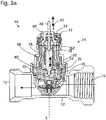
- FIG. 3a shows schematically the flow through the valve 10 from the first fluid port 16 as inlet port to the second fluid port 18 as outlet port. As shown there, the flow traverses the valve seat ring 29 and presetting sleeve 40 after passing through the valve opening 30 defined by the valve seat 28 and the valve stem 22.
- the regulating function of the presetting element 38 therefore affects the flow in series to the regulating function of the valve seat 28 and valve element 20.
- Presetting is thus effected by choosing a suitable rotation position of the presetting element 38 by means of the handle 32. As the presetting element is rotated, the central portion 82 remains stationary.
- the handle 32 is ring-shaped and surrounds an upper part of the central portion 82.
- a presetting indicator 94 is provided comprising a presetting position marker 90 and a presetting position scale 92.
- the presetting position marker 90 is shaped as the tip of an arrow and provided on the stuffing box 60, which is part of the central portion 82.
- the presetting position scale 92 is provided on the outer surface of the handle 32 and comprises numbers serving as marks for different presetting positions spaced at equal distances around the central portion 82.
- the presetting indicator 94 and the presetting position scale 92 are arranged in the same axial position, e.g. at the same height along the longitudinal axis X, as shown e.g. in Fig. 1, Fig. 2 . They are not offset, but arranged adjacent to each other, which facilitates reading.
- the presetting position marker 90 points to different marks of the presetting position scale 92, thereby indicating the chosen presetting position.
- a specific presetting position may be reached, corresponding to a maximum flow regulated by a corresponding degree of overlap between the radial flow opening (not shown) formed in the presetting sleeve 40 and the radial flow channel opening (not shown) formed in the valve seat ring 29, which is part of the central portion 82.
- valve opening 30 is directed in opening direction of the valve stem 22, i.e. the fluid flows first through the valve seat 28 before contacting the valve stem 22. This is the preferred flow direction, because a flow of fluid in reverse closing direction could move the valve stem 22.
- valve 10 is shown in figure 3a in a position to be used for a flow of the heating fluid from the first fluid port 16 to the second fluid port 18, the valve 10 is also useable for reverse flow direction.
- the entire valve insert 14 may be rotated 180° around the longitudinal axis X, so that the connection of the first and second fluid ports 16, 18 to the valve seat 38 is reversed.
- Rotation of the valve insert 14 may be effected by rotating the central portion 82, the top of which protrudes from the valve 10 as visible in particular from Fig. 1 .
- a coupling element 88 is provided which allows rotational coupling to a reversing tool 96.
- the reversing tool 96 is provided with an engagement structure (not shown) shaped as a negative of the coupling element 88, such that it engages the top of the central portion 82 and couples thereto.
- the coupling element 88 provided on top of the central portion 82 has the shape of an arrow.
- the tip of the arrow is used as presetting position marker 90.
- the arrow serves a further purpose in that it is a direction indicator 91 which points in a specific direction between the first and second fluid ports 16, 18, namely the flow direction which ensures that the fluid flowing through the valve 10 will traverse the valve opening 30 in the preferred direction (opening direction of the valve 10). If the flow direction of the valve is reversed by rotating the central portion 82 as explained above, the arrow forming the direction indicator 91 will indicate the reverse flow direction.
- presetting element 38 is rotated along with the central portion 82, such that upon reversal of the valve 10 as explained the presetting position thereof relative to the central portion 82, more specifically to the valve seat ring 29, is maintained.
Landscapes
- Engineering & Computer Science (AREA)
- General Engineering & Computer Science (AREA)
- Mechanical Engineering (AREA)
- Physics & Mathematics (AREA)
- Thermal Sciences (AREA)
- Chemical & Material Sciences (AREA)
- Combustion & Propulsion (AREA)
- General Physics & Mathematics (AREA)
- Automation & Control Theory (AREA)
- Fluid Mechanics (AREA)
- Indication Of The Valve Opening Or Closing Status (AREA)
Abstract
Description
- The invention relates to a valve, e.g. for use as a thermostat valve in a heating or cooling system.
-
DE-G 1745 874 describes a stop valve with adjustable presetting, in particular for heating systems. A turning handle is connected to an axle bolt carrying a valve body acting as a cutoff element for a ring seat. A tube shutter has an inclined lower edge such that rotation may release partial free cross-sections of an inlet port. The shutter is locked by a screw. After loosening of the screw, the presetting of the shutter may be adjusted by use of a wrench. - It may be considered an object to provide a valve which may be adjusted in a simple and exact manner.
- This is addressed by a valve according to claim 1. Dependent claims refer to preferred embodiments.
- A valve according to the invention comprises a central portion including elements disposed to regulate a fluid flow through a valve opening. A valve element is movable relative to a valve seat to adjust the valve opening. The valve preferably comprises first and second fluid ports, by which it may be connected e.g. to a cooling or heating system. By adjusting the valve opening by positioning the valve element relative to the valve seat, the fluid flow between the fluid ports may be regulated.
- The valve further comprises a presetting element to adjust a maximum flow through the valve opening. The presetting element is rotatable around the central portion. The central portion is configured to remain stationary as the presetting element is being rotated.
- The presetting element is rotatable to adjust the maximum flow preferably by changing an effective free cross-section of a flow channel for the fluid flow through the valve. With respect to the fluid flow, the flow channel is preferably arranged in series to the valve seat. A larger effective free cross-section of the flow channel will thus allow a higher maximum flow through the valve, whereas a smaller effective free cross-section will stronger limit the maximum flow. Thus, the rotation position of the presetting element determines the maximum flow through the valve without changing the positioning of the valve element and valve seat.
- The valve construction according to the invention, providing a stationary central portion around which the presetting element may be rotated allows a simple structure. The rotation position of the presetting element may easily be determined in relation to the stationary central portion, such that presetting may be effected in a precise manner.
- According to a preferred embodiment, the valve element is movable relative to the valve seat in axial direction, i.e. in a direction identical or parallel to the rotation axis of the presetting element. The valve element is preferably disposed to be linearly displaced against the valve seat without rotation, i.e. while remaining in a fixed rotation position.
- In a particularly preferred embodiment, the central portion of the valve may comprise a valve pin which is slidingly arranged, i.e. can be linearly displaced along the axial direction, to act on the valve element. Preferably, the valve pin may abut against the valve element. A valve spring may act on the valve element in an opening direction of the valve, i.e. away from the valve seat. The valve pin may act on the valve element in the axial direction in a closing direction of the valve, i.e. to urge the valve pin towards the valve seat.
- The presetting element may comprise a sleeve arranged to surround at least a part of the central port. The sleeve may be arranged co-axially to the central portion to rotate around its central longitudinal axis. Preferably, the sleeve may define a free cross-section of a flow channel arranged in series to the valve seat. The cross-section is dependent on the rotating position of the presetting element. For example, the presetting element may comprise a flow opening which according to the rotating position of the presetting element may be selectively aligned with the flow channel. The flow channel may preferably be directed radially. For example, a flow channel opening may be provided within the central portion. In a particularly preferred embodiment, a degree of overlap between a radial flow opening formed in the sleeve of the presetting element and a radial flow channel opening formed in the central portion may be selected by the rotation position of the presetting element.
- Preferably, an upper part of the central portion may protrude from the valve. The upper part of the central portion may comprise a protruding valve pin, which is thus accessible for a regulating part mounted to the valve.
- In a preferred embodiment, the presetting element may comprise or be connected to a rotatable handle. The rotatable handle may preferably be ring shaped and arranged to rotate around at least a part of the central portion.
- A presetting indicator may be provided to indicate the position of the presetting element. Preferably, the presetting indicator may comprise two indicator elements movable with respect to each other, dependent on a movement of the presetting element. One of the two elements may be a presetting position marker and the other a presetting position scale. For example, the scale may comprise equidistant marks. One of the indicator elements may be provided on the handle and the other on the central portion, such that a relative movement of the handle and the central portion is indicated by the presetting indicator. Preferably, the presetting scale may be provided on the handle and the presetting position marker on the central portion.
- Preferably, the presetting position marker and the presetting position scale may be arranged adjacent to each other in the same axial position, i.e. at the same height (in upright orientation of the valve). This has the advantage that the reading of the part of the presetting position scale to which the presetting position marker points can be accurately obtained even if not observed in parallel to the longitudinal axis. Reading of the position indicated by the presetting indicator is therefore facilitated.
- In a preferred embodiment, the valve may comprise a valve insert being rotatable to reverse the flow direction through the valve opening, i.e. to switch the connection of the two sides of the valve insert to inlet and outlet ports. It is generally preferred to install the valve connected to inlet and outlet fluid ports such that the flow through the valve opening is directed in valve opening direction and not valve closing direction, i.e. such that the fluid flows first through the valve opening at the valve seat before contacting the valve element. If the flow through the valve opening is in reverse direction, i.e. parallel to the closing direction of the valve, it is possible for the fluid flow to move the valve element in the closing direction. In the case of a reversible valve insert, the valve may be installed regardless of flow direction between output and input ports, because by rotating the valve insert it is always possible to achieve a desired flow direction.
- Preferably, the valve insert may be rotatable by rotating the central portion. While the central portion remains stationary with regard to a rotation of the presetting element as described above, a rotation of the central portion may be used to rotate the entire valve insert. In this way, reversing of the flow direction through the valve is significantly facilitated. Preferably, a top of the central portion protruding from the top of the valve may be used to rotate the valve insert. A coupling element made be provided on the top of the central portion to be coupled with a reversing tool to rotate the valve insert. It is also preferred to provide a direction indicator on the top of the central portion to indicate the current flow direction, e.g. in the shape of an arrow. This significantly facilitates correct installation.
- In a particularly preferred embodiment, one and the same element, preferably in the shape of an arrow, may serve both as a direction indicator and as a presetting position marker of a presetting position indicator.
- If the valve insert is rotated by rotating the central portion, the positioning of the presetting element relative to the central portion may remain unchanged, i.e. the presetting element may rotate along with the central portion. This has the advantage that presetting is maintained.
- Preferably, the valve may comprise parts of metal and/or plastic material. In particular, it may be preferred to provide the central portion to be made at least partially, preferably entirely out of a plastic material.
- Preferred embodiments of the invention will now be described with reference to the drawings, wherein
- Fig. 1
- shows a perspective view of an embodiment of a valve;
- Fig. 2
- shows a side view of the valve of
figure 1 ; - Fig. 3a
- shows a sectional view along A..A in
figure 1 ; - Fig. 3b
- shows the sectional view of
Fig. 3a with a valve insert rotated; - Fig. 4
- shows an exploded sectional view of the valve of
figures 1-3b . - The figures show a
valve 10 including avalve insert 14 inserted in avalve housing 12 with a firstfluid port 16 and secondfluid port 18. - The depicted embodiment of a
valve 10 is the lower half of a thermostat valve which controls the flow of heating fluid between a first and secondfluid port valve pin 24 along a longitudinal axis X. Thevalve 10 may be connected with itsfluid ports valve 10, a thermostat (not shown) may be mounted on top of the valve. The thermostat may determine a desired amount of heating fluid to pass thorough thevalve 10. To regulate the fluid flow between thefluid ports valve pin 24. The thermostat thus sets the axial position of thevalve pin 24 according to a desired heat flow, depending on the current room temperature in relation to a selected heating setting. - As visible from the sectional view of
figure 3a , thevalve pin 24 abuts against a valve element 20 (valve stem 22). Thevalve pin 24 may depress thevalve stem 22 in closing direction of thevalve 10 against the action of avalve spring 26. The valve stem 22 is thus movable in longitudinal direction relative to avalve seat 28 provided as an opening in avalve seat ring 29. The free cross-section of avalve opening 30 formed between the end of thevalve stem 22 and thevalve seat 28 is thus regulated by longitudinal movement of thevalve stem 22. As shown as a dotted line inFig. 3a , fluid from the firstfluid port 16 passes through thevalve opening 30 to thesecond fluid port 18. -
Fig. 4 shows in an exploded, sectional view thevalve housing 12, thevalve insert 14 and avalve top 86. - The
valve insert 14 includes acentral portion 82 and apresetting element 38. Thevalve top 86 covers thevalve insert 14 and fixes it to thevalve housing 12 by a screw connection. Ahandle 32 it mounted on top of thevalve top 86. Aring element 33 is provided between thecentral portion 82 and thehandle 32, surrounding thecentral portion 82. - The
valve housing 12 andvalve top 86 are made of metal, preferably brass. Further, thevalve spring 26 and anut 62 axially fixing thehandle 38 are made of metal. The remaining parts of thevalve insert 14 are made of a plastic material and may be formed by injection molding. - As visible in particular from
Fig. 4 , thecentral portion 82 comprises alower part 46 of the valve, including arevolver seal 84. Therevolver seal 84 is arranged to seal thevalve insert 14 against thevalve housing 12. InFig. 4 , therevolver seal 84 is shown facing the firstfluid port 16. As will be explained below, thevalve insert 14 is rotatable by 180° around the central longitudinal axis X to reverse the flow direction through thevalve 10, such that therevolver seal 84 is then facing thesecond fluid port 18 as shown inFig 3b . - The
central portion 82 further comprises thevalve seat ring 29 and thevalve element 20 with thevalve spring 26 as described above. Thevalve element 20 is axially movable within avalve sleeve 78, which is also part of thecentral portion 82. Further, astuffing box 60 provided to slidingly mount thevalve pin 24 forms part of thecentral portion 82. - The above described elements of the
central portion 82 are all arranged rotationally fixed to each other. While they remain separate parts and are still separable - e.g. thestuffing box 60 with thevalve pin 24 is axially held by anut 62 screwed onto the valve top 86 - thestuffing box 60,valve sleeve 78,valve seat ring 29, andlower part 46 are interlocked with each other such that they cannot be rotated relative to each other around the longitudinal axis X. - The
valve 10 further comprises a presetting function by which a selectable flow resistance for the flow path connecting the first andsecond ports valve opening 30. The ring-shapedhandle 32 may be manually rotated around the longitudinal axis X. Thehandle 32 is rotationally coupled via a finger 34 (Fig. 4 ) andcutout 36 to apresetting element 38 including apresetting sleeve 40 arranged to surround thevalve stem 22 and thevalve seat ring 29. Thering element 33 is also rotationally coupled to thehandle 32 and rotates therewith relative to thecentral portion 82. - The
presetting element 38 is rotatable around the longitudinal axis X. Thepresetting sleeve 40 comprises a radial flow opening (not shown), and thevalve seat ring 29 comprises a radial flow channel opening (not shown). By relative rotational positioning of thepresetting element 38 relative to thevalve seat ring 29, the flow opening and flow channel opening can be brought into different overlap positions, thereby selecting the size of the effective cross-section available for the fluid flow. - While the radial flow opening in the
presetting sleeve 40 and the corresponding radial flow channel opening in thevalve seat ring 29 are not shown,Fig. 3a shows schematically the flow through thevalve 10 from the firstfluid port 16 as inlet port to thesecond fluid port 18 as outlet port. As shown there, the flow traverses thevalve seat ring 29 and presettingsleeve 40 after passing through thevalve opening 30 defined by thevalve seat 28 and thevalve stem 22. The regulating function of thepresetting element 38 therefore affects the flow in series to the regulating function of thevalve seat 28 andvalve element 20. - Presetting is thus effected by choosing a suitable rotation position of the
presetting element 38 by means of thehandle 32. As the presetting element is rotated, thecentral portion 82 remains stationary. - As explained and visible e.g. from
Fig. 1 , thehandle 32 is ring-shaped and surrounds an upper part of thecentral portion 82. Apresetting indicator 94 is provided comprising apresetting position marker 90 and apresetting position scale 92. Thepresetting position marker 90 is shaped as the tip of an arrow and provided on thestuffing box 60, which is part of thecentral portion 82. Thepresetting position scale 92 is provided on the outer surface of thehandle 32 and comprises numbers serving as marks for different presetting positions spaced at equal distances around thecentral portion 82. - The
presetting indicator 94 and thepresetting position scale 92 are arranged in the same axial position, e.g. at the same height along the longitudinal axis X, as shown e.g. inFig. 1, Fig. 2 . They are not offset, but arranged adjacent to each other, which facilitates reading. - As the
presetting element 38 and handle 32 are rotated relative to thecentral portion 82 to adjust the presetting, thepresetting position marker 90 points to different marks of thepresetting position scale 92, thereby indicating the chosen presetting position. Thus, a specific presetting position may be reached, corresponding to a maximum flow regulated by a corresponding degree of overlap between the radial flow opening (not shown) formed in thepresetting sleeve 40 and the radial flow channel opening (not shown) formed in thevalve seat ring 29, which is part of thecentral portion 82. - It should be noted that as shown in
Fig. 3a the fluid flow through thevalve opening 30 is directed in opening direction of thevalve stem 22, i.e. the fluid flows first through thevalve seat 28 before contacting thevalve stem 22. This is the preferred flow direction, because a flow of fluid in reverse closing direction could move thevalve stem 22. - While the
valve 10 is shown infigure 3a in a position to be used for a flow of the heating fluid from the firstfluid port 16 to thesecond fluid port 18, thevalve 10 is also useable for reverse flow direction. Theentire valve insert 14 may be rotated 180° around the longitudinal axis X, so that the connection of the first andsecond fluid ports valve seat 38 is reversed. - Rotation of the
valve insert 14 may be effected by rotating thecentral portion 82, the top of which protrudes from thevalve 10 as visible in particular fromFig. 1 . On top of the stuffing box 60 acoupling element 88 is provided which allows rotational coupling to a reversingtool 96. The reversingtool 96 is provided with an engagement structure (not shown) shaped as a negative of thecoupling element 88, such that it engages the top of thecentral portion 82 and couples thereto. By turning the reversing tool, e.g. by means of a handle of the reversing tool 96 (not shown), thecentral portion 82 is rotated together with thepresetting element 38, while thevalve housing 12 and thevalve top 86 remain stationary. - The
coupling element 88 provided on top of thecentral portion 82 has the shape of an arrow. As already explained, the tip of the arrow is used aspresetting position marker 90. Further, the arrow serves a further purpose in that it is a direction indicator 91 which points in a specific direction between the first andsecond fluid ports valve 10 will traverse thevalve opening 30 in the preferred direction (opening direction of the valve 10). If the flow direction of the valve is reversed by rotating thecentral portion 82 as explained above, the arrow forming the direction indicator 91 will indicate the reverse flow direction. - As a result, visible from
Fig. 3b , the connection to thefluid ports Fig. 3b , the firstfluid port 16 is connected as an outlet and secondfluid port 18 as an inlet. However, due to thevalve insert 14 being rotated as compared to the position shown inFig. 3a , the flow direction through thevalve seat 28 is the same as before, i.e. the fluid flow is directed in opening direction of thevalve stem 22. - It should be noted that the
presetting element 38 is rotated along with thecentral portion 82, such that upon reversal of thevalve 10 as explained the presetting position thereof relative to thecentral portion 82, more specifically to thevalve seat ring 29, is maintained.
Claims (14)
- Valve, comprising- a central portion (82) including a valve element (20) movable relative to a valve seat (28) to adjust a valve opening (30) to regulate a fluid flow,- wherein a presetting element (38) is provided to adjust a maximum flow through said valve opening (30),- and wherein said presetting element (38) is rotatable around said central portion (82), said central portion (82) being configured to remain stationary as said presetting element (38) is being rotated.
- Valve according to claim 1, wherein- said valve element (20) is movable in axial direction (X) relative to said valve seat (28) by linear displacement without rotation.
- Valve according to claim 2, wherein- said central portion (82) comprises a valve pin (24) slidingly arranged to act on said valve element (20) in said axial direction (X).
- Valve according to one of the above claims, wherein- said presetting element (38) comprises a sleeve (40) arranged to surround at least a part of said central portion (82), said sleeve (40) defining a free cross-section of a flow channel arranged in series to said valve seat (28),- wherein said free cross-section is dependent on a rotating position of said presetting element (38).
- Valve according to one of the above claims, wherein- an upper part of said central portion (82) protrudes from said valve (10).
- Valve according to one of the above claims, wherein- said presetting element (38) comprises or is connected to a rotatable handle (32),- said handle (32) being ring shaped and arranged to rotate around at least a part of said central portion (82).
- Valve according to claim 6, wherein- a presetting indicator (94) is provided comprising at least two indicator elements movable with respect to each other together with a movement of said presetting element (38), one of said two elements being a presetting position scale (92) and the other a presetting position marker (90),- wherein one of said indicator elements (90, 92) is provided on said handle (32) and the other on said central portion (82).
- Valve according to claim 7, wherein- said presetting position marker (90) and said presetting position scale (92) are arranged adjacent to each other in the same axial position.
- Valve according to one of the above claims, wherein- said valve (10) comprises a valve insert (14) rotatable to reverse a flow direction through said valve opening (30).
- Valve according to claim 9, wherein- said valve insert (14) is rotatable by rotating said central portion (82).
- Valve according to claim 10, wherein- said central portion (82) comprises a direction indicator (91) for a flow direction.
- Valve according to claim 11 and 7 or 8, wherein- an arrow shaped element serves as direction indicator (91) and presetting position marker (90).
- Valve according to one of claims 9 - 12, wherein- a top of said central portion (82) provides a coupling element (90) which may be coupled to a reversing tool (96) to rotate said valve insert (14).
- Valve according to one of the above claims, wherein- said central portion (82) is at least partly made of a plastic material.
Priority Applications (3)
| Application Number | Priority Date | Filing Date | Title |
|---|---|---|---|
| EP18195624.4A EP3627021B1 (en) | 2018-09-20 | 2018-09-20 | Valve with rotatable presetting element |
| PL18195624T PL3627021T3 (en) | 2018-09-20 | 2018-09-20 | Valve with rotatable presetting element |
| ES18195624T ES2883689T3 (en) | 2018-09-20 | 2018-09-20 | Valve with rotary presetting element |
Applications Claiming Priority (1)
| Application Number | Priority Date | Filing Date | Title |
|---|---|---|---|
| EP18195624.4A EP3627021B1 (en) | 2018-09-20 | 2018-09-20 | Valve with rotatable presetting element |
Publications (2)
| Publication Number | Publication Date |
|---|---|
| EP3627021A1 true EP3627021A1 (en) | 2020-03-25 |
| EP3627021B1 EP3627021B1 (en) | 2021-06-02 |
Family
ID=63667733
Family Applications (1)
| Application Number | Title | Priority Date | Filing Date |
|---|---|---|---|
| EP18195624.4A Active EP3627021B1 (en) | 2018-09-20 | 2018-09-20 | Valve with rotatable presetting element |
Country Status (3)
| Country | Link |
|---|---|
| EP (1) | EP3627021B1 (en) |
| ES (1) | ES2883689T3 (en) |
| PL (1) | PL3627021T3 (en) |
Cited By (1)
| Publication number | Priority date | Publication date | Assignee | Title |
|---|---|---|---|---|
| EP4201594A1 (en) * | 2021-12-22 | 2023-06-28 | Purmo Group Sweden AB | Heat regulation control valve adjustment tool |
Citations (3)
| Publication number | Priority date | Publication date | Assignee | Title |
|---|---|---|---|---|
| BE838649A (en) * | 1975-02-17 | 1976-06-16 | ADJUSTING VALVE FOR RADIATORS | |
| EP3193050A1 (en) * | 2016-01-15 | 2017-07-19 | Danfoss A/S | Valve, in particular heat exchanger valve |
| EP3193049A1 (en) * | 2016-01-15 | 2017-07-19 | Danfoss A/S | Valve |
Family Cites Families (1)
| Publication number | Priority date | Publication date | Assignee | Title |
|---|---|---|---|---|
| CN103511637B (en) * | 2012-06-29 | 2017-06-09 | 丹佛斯公司 | Constant temperature controlled valve |
-
2018
- 2018-09-20 PL PL18195624T patent/PL3627021T3/en unknown
- 2018-09-20 EP EP18195624.4A patent/EP3627021B1/en active Active
- 2018-09-20 ES ES18195624T patent/ES2883689T3/en active Active
Patent Citations (3)
| Publication number | Priority date | Publication date | Assignee | Title |
|---|---|---|---|---|
| BE838649A (en) * | 1975-02-17 | 1976-06-16 | ADJUSTING VALVE FOR RADIATORS | |
| EP3193050A1 (en) * | 2016-01-15 | 2017-07-19 | Danfoss A/S | Valve, in particular heat exchanger valve |
| EP3193049A1 (en) * | 2016-01-15 | 2017-07-19 | Danfoss A/S | Valve |
Cited By (1)
| Publication number | Priority date | Publication date | Assignee | Title |
|---|---|---|---|---|
| EP4201594A1 (en) * | 2021-12-22 | 2023-06-28 | Purmo Group Sweden AB | Heat regulation control valve adjustment tool |
Also Published As
| Publication number | Publication date |
|---|---|
| PL3627021T3 (en) | 2021-12-06 |
| EP3627021B1 (en) | 2021-06-02 |
| ES2883689T3 (en) | 2021-12-09 |
Similar Documents
| Publication | Publication Date | Title |
|---|---|---|
| US7967023B2 (en) | Control valve | |
| CN101825186B (en) | Flow regulator | |
| DK178181B1 (en) | A control valve | |
| US9285059B2 (en) | Control valve | |
| EP0614033A1 (en) | Temperature responsive 3-way line valve with shape memory alloy actuator | |
| SE528703C2 (en) | Device for flow control of a medium in a heating and cooling system | |
| CN113544618A (en) | Barrel flow rate adjustment assembly with compensation chamber and hydraulic valve including barrel flow rate adjustment assembly | |
| EP3627021B1 (en) | Valve with rotatable presetting element | |
| US20090321672A1 (en) | Adjustable Regulator Insert | |
| CN105829986B (en) | Pressure independent dynamic balancing valve for flow control | |
| US11797031B2 (en) | Cartridge flow rate adjusting assembly and hydraulic flow rate control valve with a dual adjusting scale | |
| WO2009006893A1 (en) | A control valve | |
| KR20180059545A (en) | A display device relating to an open state and / or a closed state of a tap or pressure- | |
| EP1154176B1 (en) | Insert valve | |
| US9964964B2 (en) | Automatic balancing valve with preset flow rate | |
| EP3627015A1 (en) | Method of operating a valve with a dynamic unit | |
| EP2322828A1 (en) | Valve with sliding closing element | |
| RU2784132C1 (en) | Balancing valve | |
| EP3203346A1 (en) | Valve, in particular heat exchanger valve | |
| EP3193058B1 (en) | Valve | |
| EP4685606A1 (en) | A control valve for selectively regulating fluid flow from two sources | |
| EP3627022A1 (en) | Valve with presetting element | |
| SE459763B (en) | Thermostat-controlled return valve for radiator | |
| WO2001090616A1 (en) | Valve sub-assembly |
Legal Events
| Date | Code | Title | Description |
|---|---|---|---|
| PUAI | Public reference made under article 153(3) epc to a published international application that has entered the european phase |
Free format text: ORIGINAL CODE: 0009012 |
|
| STAA | Information on the status of an ep patent application or granted ep patent |
Free format text: STATUS: THE APPLICATION HAS BEEN PUBLISHED |
|
| AK | Designated contracting states |
Kind code of ref document: A1 Designated state(s): AL AT BE BG CH CY CZ DE DK EE ES FI FR GB GR HR HU IE IS IT LI LT LU LV MC MK MT NL NO PL PT RO RS SE SI SK SM TR |
|
| AX | Request for extension of the european patent |
Extension state: BA ME |
|
| STAA | Information on the status of an ep patent application or granted ep patent |
Free format text: STATUS: REQUEST FOR EXAMINATION WAS MADE |
|
| STAA | Information on the status of an ep patent application or granted ep patent |
Free format text: STATUS: EXAMINATION IS IN PROGRESS |
|
| 17P | Request for examination filed |
Effective date: 20200911 |
|
| RBV | Designated contracting states (corrected) |
Designated state(s): AL AT BE BG CH CY CZ DE DK EE ES FI FR GB GR HR HU IE IS IT LI LT LU LV MC MK MT NL NO PL PT RO RS SE SI SK SM TR |
|
| 17Q | First examination report despatched |
Effective date: 20201009 |
|
| GRAP | Despatch of communication of intention to grant a patent |
Free format text: ORIGINAL CODE: EPIDOSNIGR1 |
|
| STAA | Information on the status of an ep patent application or granted ep patent |
Free format text: STATUS: GRANT OF PATENT IS INTENDED |
|
| INTG | Intention to grant announced |
Effective date: 20210310 |
|
| GRAS | Grant fee paid |
Free format text: ORIGINAL CODE: EPIDOSNIGR3 |
|
| GRAA | (expected) grant |
Free format text: ORIGINAL CODE: 0009210 |
|
| STAA | Information on the status of an ep patent application or granted ep patent |
Free format text: STATUS: THE PATENT HAS BEEN GRANTED |
|
| REG | Reference to a national code |
Ref country code: CH Ref legal event code: EP |
|
| AK | Designated contracting states |
Kind code of ref document: B1 Designated state(s): AL AT BE BG CH CY CZ DE DK EE ES FI FR GB GR HR HU IE IS IT LI LT LU LV MC MK MT NL NO PL PT RO RS SE SI SK SM TR |
|
| REG | Reference to a national code |
Ref country code: GB Ref legal event code: FG4D |
|
| REG | Reference to a national code |
Ref country code: AT Ref legal event code: REF Ref document number: 1398760 Country of ref document: AT Kind code of ref document: T Effective date: 20210615 |
|
| REG | Reference to a national code |
Ref country code: IE Ref legal event code: FG4D |
|
| REG | Reference to a national code |
Ref country code: DE Ref legal event code: R096 Ref document number: 602018017935 Country of ref document: DE |
|
| REG | Reference to a national code |
Ref country code: LT Ref legal event code: MG9D |
|
| PG25 | Lapsed in a contracting state [announced via postgrant information from national office to epo] |
Ref country code: FI Free format text: LAPSE BECAUSE OF FAILURE TO SUBMIT A TRANSLATION OF THE DESCRIPTION OR TO PAY THE FEE WITHIN THE PRESCRIBED TIME-LIMIT Effective date: 20210602 Ref country code: HR Free format text: LAPSE BECAUSE OF FAILURE TO SUBMIT A TRANSLATION OF THE DESCRIPTION OR TO PAY THE FEE WITHIN THE PRESCRIBED TIME-LIMIT Effective date: 20210602 Ref country code: LT Free format text: LAPSE BECAUSE OF FAILURE TO SUBMIT A TRANSLATION OF THE DESCRIPTION OR TO PAY THE FEE WITHIN THE PRESCRIBED TIME-LIMIT Effective date: 20210602 Ref country code: BG Free format text: LAPSE BECAUSE OF FAILURE TO SUBMIT A TRANSLATION OF THE DESCRIPTION OR TO PAY THE FEE WITHIN THE PRESCRIBED TIME-LIMIT Effective date: 20210902 |
|
| REG | Reference to a national code |
Ref country code: NL Ref legal event code: MP Effective date: 20210602 |
|
| PG25 | Lapsed in a contracting state [announced via postgrant information from national office to epo] |
Ref country code: NO Free format text: LAPSE BECAUSE OF FAILURE TO SUBMIT A TRANSLATION OF THE DESCRIPTION OR TO PAY THE FEE WITHIN THE PRESCRIBED TIME-LIMIT Effective date: 20210902 Ref country code: LV Free format text: LAPSE BECAUSE OF FAILURE TO SUBMIT A TRANSLATION OF THE DESCRIPTION OR TO PAY THE FEE WITHIN THE PRESCRIBED TIME-LIMIT Effective date: 20210602 Ref country code: RS Free format text: LAPSE BECAUSE OF FAILURE TO SUBMIT A TRANSLATION OF THE DESCRIPTION OR TO PAY THE FEE WITHIN THE PRESCRIBED TIME-LIMIT Effective date: 20210602 Ref country code: SE Free format text: LAPSE BECAUSE OF FAILURE TO SUBMIT A TRANSLATION OF THE DESCRIPTION OR TO PAY THE FEE WITHIN THE PRESCRIBED TIME-LIMIT Effective date: 20210602 Ref country code: GR Free format text: LAPSE BECAUSE OF FAILURE TO SUBMIT A TRANSLATION OF THE DESCRIPTION OR TO PAY THE FEE WITHIN THE PRESCRIBED TIME-LIMIT Effective date: 20210903 |
|
| REG | Reference to a national code |
Ref country code: ES Ref legal event code: FG2A Ref document number: 2883689 Country of ref document: ES Kind code of ref document: T3 Effective date: 20211209 |
|
| REG | Reference to a national code |
Ref country code: AT Ref legal event code: UEP Ref document number: 1398760 Country of ref document: AT Kind code of ref document: T Effective date: 20210602 |
|
| PG25 | Lapsed in a contracting state [announced via postgrant information from national office to epo] |
Ref country code: SM Free format text: LAPSE BECAUSE OF FAILURE TO SUBMIT A TRANSLATION OF THE DESCRIPTION OR TO PAY THE FEE WITHIN THE PRESCRIBED TIME-LIMIT Effective date: 20210602 Ref country code: SK Free format text: LAPSE BECAUSE OF FAILURE TO SUBMIT A TRANSLATION OF THE DESCRIPTION OR TO PAY THE FEE WITHIN THE PRESCRIBED TIME-LIMIT Effective date: 20210602 Ref country code: EE Free format text: LAPSE BECAUSE OF FAILURE TO SUBMIT A TRANSLATION OF THE DESCRIPTION OR TO PAY THE FEE WITHIN THE PRESCRIBED TIME-LIMIT Effective date: 20210602 Ref country code: CZ Free format text: LAPSE BECAUSE OF FAILURE TO SUBMIT A TRANSLATION OF THE DESCRIPTION OR TO PAY THE FEE WITHIN THE PRESCRIBED TIME-LIMIT Effective date: 20210602 Ref country code: NL Free format text: LAPSE BECAUSE OF FAILURE TO SUBMIT A TRANSLATION OF THE DESCRIPTION OR TO PAY THE FEE WITHIN THE PRESCRIBED TIME-LIMIT Effective date: 20210602 Ref country code: RO Free format text: LAPSE BECAUSE OF FAILURE TO SUBMIT A TRANSLATION OF THE DESCRIPTION OR TO PAY THE FEE WITHIN THE PRESCRIBED TIME-LIMIT Effective date: 20210602 Ref country code: PT Free format text: LAPSE BECAUSE OF FAILURE TO SUBMIT A TRANSLATION OF THE DESCRIPTION OR TO PAY THE FEE WITHIN THE PRESCRIBED TIME-LIMIT Effective date: 20211004 |
|
| REG | Reference to a national code |
Ref country code: DE Ref legal event code: R097 Ref document number: 602018017935 Country of ref document: DE |
|
| PLBE | No opposition filed within time limit |
Free format text: ORIGINAL CODE: 0009261 |
|
| STAA | Information on the status of an ep patent application or granted ep patent |
Free format text: STATUS: NO OPPOSITION FILED WITHIN TIME LIMIT |
|
| PG25 | Lapsed in a contracting state [announced via postgrant information from national office to epo] |
Ref country code: DK Free format text: LAPSE BECAUSE OF FAILURE TO SUBMIT A TRANSLATION OF THE DESCRIPTION OR TO PAY THE FEE WITHIN THE PRESCRIBED TIME-LIMIT Effective date: 20210602 |
|
| REG | Reference to a national code |
Ref country code: CH Ref legal event code: PL |
|
| 26N | No opposition filed |
Effective date: 20220303 |
|
| REG | Reference to a national code |
Ref country code: BE Ref legal event code: MM Effective date: 20210930 |
|
| PG25 | Lapsed in a contracting state [announced via postgrant information from national office to epo] |
Ref country code: MC Free format text: LAPSE BECAUSE OF FAILURE TO SUBMIT A TRANSLATION OF THE DESCRIPTION OR TO PAY THE FEE WITHIN THE PRESCRIBED TIME-LIMIT Effective date: 20210602 Ref country code: AL Free format text: LAPSE BECAUSE OF FAILURE TO SUBMIT A TRANSLATION OF THE DESCRIPTION OR TO PAY THE FEE WITHIN THE PRESCRIBED TIME-LIMIT Effective date: 20210602 |
|
| PG25 | Lapsed in a contracting state [announced via postgrant information from national office to epo] |
Ref country code: LU Free format text: LAPSE BECAUSE OF NON-PAYMENT OF DUE FEES Effective date: 20210920 Ref country code: IT Free format text: LAPSE BECAUSE OF FAILURE TO SUBMIT A TRANSLATION OF THE DESCRIPTION OR TO PAY THE FEE WITHIN THE PRESCRIBED TIME-LIMIT Effective date: 20210602 Ref country code: IE Free format text: LAPSE BECAUSE OF NON-PAYMENT OF DUE FEES Effective date: 20210920 Ref country code: BE Free format text: LAPSE BECAUSE OF NON-PAYMENT OF DUE FEES Effective date: 20210930 |
|
| PG25 | Lapsed in a contracting state [announced via postgrant information from national office to epo] |
Ref country code: LI Free format text: LAPSE BECAUSE OF NON-PAYMENT OF DUE FEES Effective date: 20210930 Ref country code: CH Free format text: LAPSE BECAUSE OF NON-PAYMENT OF DUE FEES Effective date: 20210930 |
|
| PG25 | Lapsed in a contracting state [announced via postgrant information from national office to epo] |
Ref country code: CY Free format text: LAPSE BECAUSE OF FAILURE TO SUBMIT A TRANSLATION OF THE DESCRIPTION OR TO PAY THE FEE WITHIN THE PRESCRIBED TIME-LIMIT Effective date: 20210602 |
|
| P01 | Opt-out of the competence of the unified patent court (upc) registered |
Effective date: 20230617 |
|
| PG25 | Lapsed in a contracting state [announced via postgrant information from national office to epo] |
Ref country code: HU Free format text: LAPSE BECAUSE OF FAILURE TO SUBMIT A TRANSLATION OF THE DESCRIPTION OR TO PAY THE FEE WITHIN THE PRESCRIBED TIME-LIMIT; INVALID AB INITIO Effective date: 20180920 |
|
| PG25 | Lapsed in a contracting state [announced via postgrant information from national office to epo] |
Ref country code: MK Free format text: LAPSE BECAUSE OF FAILURE TO SUBMIT A TRANSLATION OF THE DESCRIPTION OR TO PAY THE FEE WITHIN THE PRESCRIBED TIME-LIMIT Effective date: 20210602 |
|
| PG25 | Lapsed in a contracting state [announced via postgrant information from national office to epo] |
Ref country code: MT Free format text: LAPSE BECAUSE OF FAILURE TO SUBMIT A TRANSLATION OF THE DESCRIPTION OR TO PAY THE FEE WITHIN THE PRESCRIBED TIME-LIMIT Effective date: 20210602 |
|
| PGFP | Annual fee paid to national office [announced via postgrant information from national office to epo] |
Ref country code: DE Payment date: 20250805 Year of fee payment: 8 |
|
| PGFP | Annual fee paid to national office [announced via postgrant information from national office to epo] |
Ref country code: PL Payment date: 20250812 Year of fee payment: 8 Ref country code: TR Payment date: 20250912 Year of fee payment: 8 |
|
| PGFP | Annual fee paid to national office [announced via postgrant information from national office to epo] |
Ref country code: GB Payment date: 20250731 Year of fee payment: 8 |
|
| PGFP | Annual fee paid to national office [announced via postgrant information from national office to epo] |
Ref country code: FR Payment date: 20250821 Year of fee payment: 8 Ref country code: AT Payment date: 20250827 Year of fee payment: 8 |
|
| PGFP | Annual fee paid to national office [announced via postgrant information from national office to epo] |
Ref country code: ES Payment date: 20251016 Year of fee payment: 8 |