EP3627018A1 - Cylinder drive manifold device and cylinder drive apparatus - Google Patents
Cylinder drive manifold device and cylinder drive apparatus Download PDFInfo
- Publication number
- EP3627018A1 EP3627018A1 EP18802075.4A EP18802075A EP3627018A1 EP 3627018 A1 EP3627018 A1 EP 3627018A1 EP 18802075 A EP18802075 A EP 18802075A EP 3627018 A1 EP3627018 A1 EP 3627018A1
- Authority
- EP
- European Patent Office
- Prior art keywords
- port
- fluid
- manifold
- connection
- ports
- Prior art date
- Legal status (The legal status is an assumption and is not a legal conclusion. Google has not performed a legal analysis and makes no representation as to the accuracy of the status listed.)
- Granted
Links
Images






Classifications
-
- F—MECHANICAL ENGINEERING; LIGHTING; HEATING; WEAPONS; BLASTING
- F15—FLUID-PRESSURE ACTUATORS; HYDRAULICS OR PNEUMATICS IN GENERAL
- F15B—SYSTEMS ACTING BY MEANS OF FLUIDS IN GENERAL; FLUID-PRESSURE ACTUATORS, e.g. SERVOMOTORS; DETAILS OF FLUID-PRESSURE SYSTEMS, NOT OTHERWISE PROVIDED FOR
- F15B11/00—Servomotor systems without provision for follow-up action; Circuits therefor
- F15B11/16—Servomotor systems without provision for follow-up action; Circuits therefor with two or more servomotors
-
- F—MECHANICAL ENGINEERING; LIGHTING; HEATING; WEAPONS; BLASTING
- F15—FLUID-PRESSURE ACTUATORS; HYDRAULICS OR PNEUMATICS IN GENERAL
- F15B—SYSTEMS ACTING BY MEANS OF FLUIDS IN GENERAL; FLUID-PRESSURE ACTUATORS, e.g. SERVOMOTORS; DETAILS OF FLUID-PRESSURE SYSTEMS, NOT OTHERWISE PROVIDED FOR
- F15B13/00—Details of servomotor systems ; Valves for servomotor systems
- F15B13/02—Fluid distribution or supply devices characterised by their adaptation to the control of servomotors
- F15B13/06—Fluid distribution or supply devices characterised by their adaptation to the control of servomotors for use with two or more servomotors
- F15B13/08—Assemblies of units, each for the control of a single servomotor only
- F15B13/0803—Modular units
- F15B13/0807—Manifolds
-
- F—MECHANICAL ENGINEERING; LIGHTING; HEATING; WEAPONS; BLASTING
- F15—FLUID-PRESSURE ACTUATORS; HYDRAULICS OR PNEUMATICS IN GENERAL
- F15B—SYSTEMS ACTING BY MEANS OF FLUIDS IN GENERAL; FLUID-PRESSURE ACTUATORS, e.g. SERVOMOTORS; DETAILS OF FLUID-PRESSURE SYSTEMS, NOT OTHERWISE PROVIDED FOR
- F15B11/00—Servomotor systems without provision for follow-up action; Circuits therefor
- F15B11/02—Systems essentially incorporating special features for controlling the speed or actuating force of an output member
- F15B11/024—Systems essentially incorporating special features for controlling the speed or actuating force of an output member by means of differential connection of the servomotor lines, e.g. regenerative circuits
-
- F—MECHANICAL ENGINEERING; LIGHTING; HEATING; WEAPONS; BLASTING
- F15—FLUID-PRESSURE ACTUATORS; HYDRAULICS OR PNEUMATICS IN GENERAL
- F15B—SYSTEMS ACTING BY MEANS OF FLUIDS IN GENERAL; FLUID-PRESSURE ACTUATORS, e.g. SERVOMOTORS; DETAILS OF FLUID-PRESSURE SYSTEMS, NOT OTHERWISE PROVIDED FOR
- F15B11/00—Servomotor systems without provision for follow-up action; Circuits therefor
- F15B11/06—Servomotor systems without provision for follow-up action; Circuits therefor involving features specific to the use of a compressible medium, e.g. air, steam
-
- F—MECHANICAL ENGINEERING; LIGHTING; HEATING; WEAPONS; BLASTING
- F15—FLUID-PRESSURE ACTUATORS; HYDRAULICS OR PNEUMATICS IN GENERAL
- F15B—SYSTEMS ACTING BY MEANS OF FLUIDS IN GENERAL; FLUID-PRESSURE ACTUATORS, e.g. SERVOMOTORS; DETAILS OF FLUID-PRESSURE SYSTEMS, NOT OTHERWISE PROVIDED FOR
- F15B11/00—Servomotor systems without provision for follow-up action; Circuits therefor
- F15B11/06—Servomotor systems without provision for follow-up action; Circuits therefor involving features specific to the use of a compressible medium, e.g. air, steam
- F15B11/064—Servomotor systems without provision for follow-up action; Circuits therefor involving features specific to the use of a compressible medium, e.g. air, steam with devices for saving the compressible medium
-
- F—MECHANICAL ENGINEERING; LIGHTING; HEATING; WEAPONS; BLASTING
- F15—FLUID-PRESSURE ACTUATORS; HYDRAULICS OR PNEUMATICS IN GENERAL
- F15B—SYSTEMS ACTING BY MEANS OF FLUIDS IN GENERAL; FLUID-PRESSURE ACTUATORS, e.g. SERVOMOTORS; DETAILS OF FLUID-PRESSURE SYSTEMS, NOT OTHERWISE PROVIDED FOR
- F15B13/00—Details of servomotor systems ; Valves for servomotor systems
- F15B13/02—Fluid distribution or supply devices characterised by their adaptation to the control of servomotors
- F15B13/021—Valves for interconnecting the fluid chambers of an actuator
-
- F—MECHANICAL ENGINEERING; LIGHTING; HEATING; WEAPONS; BLASTING
- F15—FLUID-PRESSURE ACTUATORS; HYDRAULICS OR PNEUMATICS IN GENERAL
- F15B—SYSTEMS ACTING BY MEANS OF FLUIDS IN GENERAL; FLUID-PRESSURE ACTUATORS, e.g. SERVOMOTORS; DETAILS OF FLUID-PRESSURE SYSTEMS, NOT OTHERWISE PROVIDED FOR
- F15B13/00—Details of servomotor systems ; Valves for servomotor systems
- F15B13/02—Fluid distribution or supply devices characterised by their adaptation to the control of servomotors
- F15B13/06—Fluid distribution or supply devices characterised by their adaptation to the control of servomotors for use with two or more servomotors
- F15B13/08—Assemblies of units, each for the control of a single servomotor only
- F15B13/0803—Modular units
- F15B13/0807—Manifolds
- F15B13/0814—Monoblock manifolds
-
- F—MECHANICAL ENGINEERING; LIGHTING; HEATING; WEAPONS; BLASTING
- F15—FLUID-PRESSURE ACTUATORS; HYDRAULICS OR PNEUMATICS IN GENERAL
- F15B—SYSTEMS ACTING BY MEANS OF FLUIDS IN GENERAL; FLUID-PRESSURE ACTUATORS, e.g. SERVOMOTORS; DETAILS OF FLUID-PRESSURE SYSTEMS, NOT OTHERWISE PROVIDED FOR
- F15B13/00—Details of servomotor systems ; Valves for servomotor systems
- F15B13/02—Fluid distribution or supply devices characterised by their adaptation to the control of servomotors
- F15B13/06—Fluid distribution or supply devices characterised by their adaptation to the control of servomotors for use with two or more servomotors
- F15B13/08—Assemblies of units, each for the control of a single servomotor only
- F15B13/0803—Modular units
- F15B13/0807—Manifolds
- F15B13/0817—Multiblock manifolds
-
- F—MECHANICAL ENGINEERING; LIGHTING; HEATING; WEAPONS; BLASTING
- F15—FLUID-PRESSURE ACTUATORS; HYDRAULICS OR PNEUMATICS IN GENERAL
- F15B—SYSTEMS ACTING BY MEANS OF FLUIDS IN GENERAL; FLUID-PRESSURE ACTUATORS, e.g. SERVOMOTORS; DETAILS OF FLUID-PRESSURE SYSTEMS, NOT OTHERWISE PROVIDED FOR
- F15B13/00—Details of servomotor systems ; Valves for servomotor systems
- F15B13/02—Fluid distribution or supply devices characterised by their adaptation to the control of servomotors
- F15B13/06—Fluid distribution or supply devices characterised by their adaptation to the control of servomotors for use with two or more servomotors
- F15B13/08—Assemblies of units, each for the control of a single servomotor only
- F15B13/0803—Modular units
- F15B13/0832—Modular valves
-
- F—MECHANICAL ENGINEERING; LIGHTING; HEATING; WEAPONS; BLASTING
- F15—FLUID-PRESSURE ACTUATORS; HYDRAULICS OR PNEUMATICS IN GENERAL
- F15B—SYSTEMS ACTING BY MEANS OF FLUIDS IN GENERAL; FLUID-PRESSURE ACTUATORS, e.g. SERVOMOTORS; DETAILS OF FLUID-PRESSURE SYSTEMS, NOT OTHERWISE PROVIDED FOR
- F15B13/00—Details of servomotor systems ; Valves for servomotor systems
- F15B13/02—Fluid distribution or supply devices characterised by their adaptation to the control of servomotors
- F15B13/06—Fluid distribution or supply devices characterised by their adaptation to the control of servomotors for use with two or more servomotors
- F15B13/08—Assemblies of units, each for the control of a single servomotor only
- F15B13/0803—Modular units
- F15B13/0832—Modular valves
- F15B13/0839—Stacked plate type valves
-
- F—MECHANICAL ENGINEERING; LIGHTING; HEATING; WEAPONS; BLASTING
- F15—FLUID-PRESSURE ACTUATORS; HYDRAULICS OR PNEUMATICS IN GENERAL
- F15B—SYSTEMS ACTING BY MEANS OF FLUIDS IN GENERAL; FLUID-PRESSURE ACTUATORS, e.g. SERVOMOTORS; DETAILS OF FLUID-PRESSURE SYSTEMS, NOT OTHERWISE PROVIDED FOR
- F15B13/00—Details of servomotor systems ; Valves for servomotor systems
- F15B13/02—Fluid distribution or supply devices characterised by their adaptation to the control of servomotors
- F15B13/06—Fluid distribution or supply devices characterised by their adaptation to the control of servomotors for use with two or more servomotors
- F15B13/08—Assemblies of units, each for the control of a single servomotor only
- F15B13/0803—Modular units
- F15B13/0871—Channels for fluid
-
- F—MECHANICAL ENGINEERING; LIGHTING; HEATING; WEAPONS; BLASTING
- F15—FLUID-PRESSURE ACTUATORS; HYDRAULICS OR PNEUMATICS IN GENERAL
- F15B—SYSTEMS ACTING BY MEANS OF FLUIDS IN GENERAL; FLUID-PRESSURE ACTUATORS, e.g. SERVOMOTORS; DETAILS OF FLUID-PRESSURE SYSTEMS, NOT OTHERWISE PROVIDED FOR
- F15B21/00—Common features of fluid actuator systems; Fluid-pressure actuator systems or details thereof, not covered by any other group of this subclass
- F15B21/008—Reduction of noise or vibration
-
- F—MECHANICAL ENGINEERING; LIGHTING; HEATING; WEAPONS; BLASTING
- F16—ENGINEERING ELEMENTS AND UNITS; GENERAL MEASURES FOR PRODUCING AND MAINTAINING EFFECTIVE FUNCTIONING OF MACHINES OR INSTALLATIONS; THERMAL INSULATION IN GENERAL
- F16K—VALVES; TAPS; COCKS; ACTUATING-FLOATS; DEVICES FOR VENTING OR AERATING
- F16K27/00—Construction of housing; Use of materials therefor
- F16K27/003—Housing formed from a plurality of the same valve elements
-
- F—MECHANICAL ENGINEERING; LIGHTING; HEATING; WEAPONS; BLASTING
- F16—ENGINEERING ELEMENTS AND UNITS; GENERAL MEASURES FOR PRODUCING AND MAINTAINING EFFECTIVE FUNCTIONING OF MACHINES OR INSTALLATIONS; THERMAL INSULATION IN GENERAL
- F16K—VALVES; TAPS; COCKS; ACTUATING-FLOATS; DEVICES FOR VENTING OR AERATING
- F16K27/00—Construction of housing; Use of materials therefor
- F16K27/02—Construction of housing; Use of materials therefor of lift valves
-
- F—MECHANICAL ENGINEERING; LIGHTING; HEATING; WEAPONS; BLASTING
- F16—ENGINEERING ELEMENTS AND UNITS; GENERAL MEASURES FOR PRODUCING AND MAINTAINING EFFECTIVE FUNCTIONING OF MACHINES OR INSTALLATIONS; THERMAL INSULATION IN GENERAL
- F16K—VALVES; TAPS; COCKS; ACTUATING-FLOATS; DEVICES FOR VENTING OR AERATING
- F16K47/00—Means in valves for absorbing fluid energy
- F16K47/04—Means in valves for absorbing fluid energy for decreasing pressure or noise level, the throttle being incorporated in the closure member
-
- F—MECHANICAL ENGINEERING; LIGHTING; HEATING; WEAPONS; BLASTING
- F15—FLUID-PRESSURE ACTUATORS; HYDRAULICS OR PNEUMATICS IN GENERAL
- F15B—SYSTEMS ACTING BY MEANS OF FLUIDS IN GENERAL; FLUID-PRESSURE ACTUATORS, e.g. SERVOMOTORS; DETAILS OF FLUID-PRESSURE SYSTEMS, NOT OTHERWISE PROVIDED FOR
- F15B13/00—Details of servomotor systems ; Valves for servomotor systems
- F15B2013/002—Modular valves, i.e. consisting of an assembly of interchangeable components
-
- F—MECHANICAL ENGINEERING; LIGHTING; HEATING; WEAPONS; BLASTING
- F15—FLUID-PRESSURE ACTUATORS; HYDRAULICS OR PNEUMATICS IN GENERAL
- F15B—SYSTEMS ACTING BY MEANS OF FLUIDS IN GENERAL; FLUID-PRESSURE ACTUATORS, e.g. SERVOMOTORS; DETAILS OF FLUID-PRESSURE SYSTEMS, NOT OTHERWISE PROVIDED FOR
- F15B2211/00—Circuits for servomotor systems
- F15B2211/30—Directional control
- F15B2211/305—Directional control characterised by the type of valves
- F15B2211/30505—Non-return valves, i.e. check valves
-
- F—MECHANICAL ENGINEERING; LIGHTING; HEATING; WEAPONS; BLASTING
- F15—FLUID-PRESSURE ACTUATORS; HYDRAULICS OR PNEUMATICS IN GENERAL
- F15B—SYSTEMS ACTING BY MEANS OF FLUIDS IN GENERAL; FLUID-PRESSURE ACTUATORS, e.g. SERVOMOTORS; DETAILS OF FLUID-PRESSURE SYSTEMS, NOT OTHERWISE PROVIDED FOR
- F15B2211/00—Circuits for servomotor systems
- F15B2211/30—Directional control
- F15B2211/31—Directional control characterised by the positions of the valve element
- F15B2211/3122—Special positions other than the pump port being connected to working ports or the working ports being connected to the return line
- F15B2211/3133—Regenerative position connecting the working ports or connecting the working ports to the pump, e.g. for high-speed approach stroke
-
- F—MECHANICAL ENGINEERING; LIGHTING; HEATING; WEAPONS; BLASTING
- F15—FLUID-PRESSURE ACTUATORS; HYDRAULICS OR PNEUMATICS IN GENERAL
- F15B—SYSTEMS ACTING BY MEANS OF FLUIDS IN GENERAL; FLUID-PRESSURE ACTUATORS, e.g. SERVOMOTORS; DETAILS OF FLUID-PRESSURE SYSTEMS, NOT OTHERWISE PROVIDED FOR
- F15B2211/00—Circuits for servomotor systems
- F15B2211/40—Flow control
- F15B2211/405—Flow control characterised by the type of flow control means or valve
- F15B2211/40515—Flow control characterised by the type of flow control means or valve with variable throttles or orifices
-
- F—MECHANICAL ENGINEERING; LIGHTING; HEATING; WEAPONS; BLASTING
- F15—FLUID-PRESSURE ACTUATORS; HYDRAULICS OR PNEUMATICS IN GENERAL
- F15B—SYSTEMS ACTING BY MEANS OF FLUIDS IN GENERAL; FLUID-PRESSURE ACTUATORS, e.g. SERVOMOTORS; DETAILS OF FLUID-PRESSURE SYSTEMS, NOT OTHERWISE PROVIDED FOR
- F15B2211/00—Circuits for servomotor systems
- F15B2211/40—Flow control
- F15B2211/405—Flow control characterised by the type of flow control means or valve
- F15B2211/40576—Assemblies of multiple valves
- F15B2211/40584—Assemblies of multiple valves the flow control means arranged in parallel with a check valve
-
- F—MECHANICAL ENGINEERING; LIGHTING; HEATING; WEAPONS; BLASTING
- F15—FLUID-PRESSURE ACTUATORS; HYDRAULICS OR PNEUMATICS IN GENERAL
- F15B—SYSTEMS ACTING BY MEANS OF FLUIDS IN GENERAL; FLUID-PRESSURE ACTUATORS, e.g. SERVOMOTORS; DETAILS OF FLUID-PRESSURE SYSTEMS, NOT OTHERWISE PROVIDED FOR
- F15B2211/00—Circuits for servomotor systems
- F15B2211/40—Flow control
- F15B2211/415—Flow control characterised by the connections of the flow control means in the circuit
- F15B2211/41554—Flow control characterised by the connections of the flow control means in the circuit being connected to a return line and a directional control valve
-
- F—MECHANICAL ENGINEERING; LIGHTING; HEATING; WEAPONS; BLASTING
- F15—FLUID-PRESSURE ACTUATORS; HYDRAULICS OR PNEUMATICS IN GENERAL
- F15B—SYSTEMS ACTING BY MEANS OF FLUIDS IN GENERAL; FLUID-PRESSURE ACTUATORS, e.g. SERVOMOTORS; DETAILS OF FLUID-PRESSURE SYSTEMS, NOT OTHERWISE PROVIDED FOR
- F15B2211/00—Circuits for servomotor systems
- F15B2211/80—Other types of control related to particular problems or conditions
- F15B2211/86—Control during or prevention of abnormal conditions
- F15B2211/8616—Control during or prevention of abnormal conditions the abnormal condition being noise or vibration
-
- F—MECHANICAL ENGINEERING; LIGHTING; HEATING; WEAPONS; BLASTING
- F15—FLUID-PRESSURE ACTUATORS; HYDRAULICS OR PNEUMATICS IN GENERAL
- F15B—SYSTEMS ACTING BY MEANS OF FLUIDS IN GENERAL; FLUID-PRESSURE ACTUATORS, e.g. SERVOMOTORS; DETAILS OF FLUID-PRESSURE SYSTEMS, NOT OTHERWISE PROVIDED FOR
- F15B2211/00—Circuits for servomotor systems
- F15B2211/80—Other types of control related to particular problems or conditions
- F15B2211/88—Control measures for saving energy
-
- F—MECHANICAL ENGINEERING; LIGHTING; HEATING; WEAPONS; BLASTING
- F15—FLUID-PRESSURE ACTUATORS; HYDRAULICS OR PNEUMATICS IN GENERAL
- F15B—SYSTEMS ACTING BY MEANS OF FLUIDS IN GENERAL; FLUID-PRESSURE ACTUATORS, e.g. SERVOMOTORS; DETAILS OF FLUID-PRESSURE SYSTEMS, NOT OTHERWISE PROVIDED FOR
- F15B2211/00—Circuits for servomotor systems
- F15B2211/80—Other types of control related to particular problems or conditions
- F15B2211/885—Control specific to the type of fluid, e.g. specific to magnetorheological fluid
- F15B2211/8855—Compressible fluids, e.g. specific to pneumatics
Definitions
- the present invention relates to a cylinder drive manifold device and a cylinder drive apparatus configured to drive a plurality of fluid pressure cylinders.
- a cylinder drive apparatus which drives a fluid pressure cylinder by supplying a fluid such as air or the like alternately to a first cylinder chamber and a second cylinder chamber that are partitioned by a piston of the fluid pressure cylinder (see, for example, Japanese Laid-Open Patent Publication No. 2001-311404 ) .
- a cylinder drive apparatus for driving the fluid pressure cylinders may be equipped respectively with a plurality of switching valves, check valves, and throttle valves.
- valve members of this type are connected mutually to one another by pipes.
- the assembly operation a pipe connecting operation, etc.
- the present invention has been devised taking into consideration the aforementioned problem, and has the object of providing a cylinder drive manifold device and a cylinder drive apparatus in which, together with enabling a reduction in the number of parts, it is possible to easily perform an assembly operation.
- a cylinder drive manifold device configured to drive a plurality of fluid pressure cylinders
- the cylinder drive manifold device comprising a block-shaped manifold in which a plurality of holes are formed through which a fluid used to drive the plurality of fluid pressure cylinders flows
- the manifold is configured to enable a plurality of switching valves to be mounted thereon, the switching valves being configured to alternately supply the fluid to a first cylinder chamber and a second cylinder chamber partitioned by a piston of each of the fluid pressure cylinders, and a plurality of check valves and a plurality of throttle valves are incorporated in the plurality of holes of the manifold.
- the plurality of holes of the manifold may include a plurality of introduction ports configured to introduce the fluid into the respective switching valves, a plurality of lead-out ports through which the fluid is guided from the respective switching valves, a plurality of first connection ports configured to enable mutual communication between the respective switching valves and the first cylinder chambers of the respective fluid pressure cylinders, a plurality of second connection ports configured to enable mutual communication between the respective switching valves and the second cylinder chambers of the respective fluid pressure cylinders, and a plurality of third connection ports configured to connect the first connection ports and the switching valves to each other, wherein, in each of the third connection ports, the check valve may be provided which allows flow of the fluid in a direction from the first connection port toward the switching valve, and which prevents flow of the fluid in a direction from the switching valve toward the first connection port, the throttle valve may be provided in the respective lead-out ports, each of the switching valves may be configured to switch between a state of communication and a
- the introduction port and the first connection port may communicate with each other, and the lead-out port and the second connection port may communicate with each other, while communication between the first connection port and the lead-out port may be blocked, and communication between the second connection port and the third connection port may be blocked, and in a second position of the switching valves, the first connection port and the lead-out port may communicate with each other, and the second connection port and the third connection port may communicate with each other, while communication between the introduction port and the first connection port may be blocked, and communication between the lead-out port and the second connection port may be blocked.
- the fluid in the first cylinder chamber of the fluid pressure cylinder is supplied to the second cylinder chamber and simultaneously discharged to the lead-out port via the first connection port, the third connection port, and the second connection port. Consequently, the fluid pressure in the second cylinder chamber increases and the fluid pressure in the first cylinder chamber rapidly decreases, and therefore, it is possible to reduce the amount of fluid that is consumed in order to drive the fluid pressure cylinder. Therefore, it is possible to achieve a saving of energy when the plurality of fluid pressure cylinders are driven.
- a fluid flow path may be formed so as to extend linearly to the check valve from an opening of the first connection port in which a connector, to which a pipe communicating with the first cylinder chamber is connectable, is configured to be mounted.
- the respective throttle valves may be variable throttle valves which are disposed at a location on the manifold that is closer to a mounting site for the plurality of switching valves than the respective check valves.
- the length of the flow paths from the switching valves to the variable throttle valves can be made comparatively short. More specifically, the volume of fluid from the switching valves to the variable throttle valves can be made comparatively small. Therefore, the flow rate (the pressure) of the fluid that is guided from the first connection ports to the third connection ports can be easily adjusted by changing the throttle opening of the variable throttle valves.
- a single supply port which communicates with each of the introduction ports and to which the fluid from a fluid supply source is supplied, may be formed in the manifold.
- a single discharge port which communicates with each of the lead-out ports and is configured to discharge the fluid to an exterior of the manifold, may be formed in the manifold, and a single silencer configured to reduce discharge noise of the fluid may be disposed in the discharge port.
- a cylinder drive apparatus is characterized by comprising the cylinder drive manifold device as described above, and a plurality of the switching valves.
- the plurality of check valves and the plurality of throttle valves are incorporated in the plurality of holes of the manifold, it is possible to reduce the number of parts, together with making it easy to perform the assembly operation.
- a cylinder drive apparatus 12 serves as an apparatus for driving a plurality of fluid pressure cylinders 14.
- Each of the fluid pressure cylinders 14 is configured in the form of an air cylinder, for example, and includes a piston 22 that partitions the interior of a cylinder unit 16 into a first cylinder chamber 18 and a second cylinder chamber 20 and that is capable of sliding reciprocally in the interior of the cylinder unit 16 under the action of a fluid pressure.
- One end of a piston rod 24 is connected to the piston 22 and the other end thereof extends from the cylinder unit 16 to the exterior.
- the fluid pressure cylinders 14 perform work such as positioning of non-illustrated workpieces or the like at times that the piston rods 24 are pushed out (expanded), and do not perform work at times that the piston rods 24 are retracted.
- the first cylinder chambers 18 are driving pressure chambers (head side cylinder chambers) located on an opposite side from the piston rods 24, and the second cylinder chambers 20 are return side pressure chambers (rod side cylinder chambers) located on the side of the piston rods 24.
- the cylinder drive apparatus 12 comprises a fluid supply source 26, a cylinder drive manifold device (hereinafter referred to as a "manifold device 10"), and a plurality of switching valves 28.
- the fluid supply source 26 supplies a high-pressure fluid, and is configured, for example, in the form of an air compressor (see FIG. 1 ).
- the manifold device 10 is equipped with a single block-shaped manifold 30 to which the plurality of switching valves 28 can be connected, and a plurality of check valves 32 and a plurality of throttle valves 34 that are incorporated in the manifold 30.
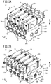
- the switching valves 28, the check valves 32, and the throttle valves 34 are provided respectively in the same number as the number of the fluid pressure cylinders 14. Although in the example shown in FIGS. 2A and 2B , five each of the switching valves 28, the check valves 32, and the throttle valves 34 are provided, the number of these valve members and the fluid pressure cylinders 14 can be arbitrarily changed.
- the manifold 30 is integrally formed in a block shape, for example, from a metal material such as aluminum or the like.
- the constituent material of the manifold 30 is not limited to being a metal material, and any arbitrary material such as a hard resin or the like can be adopted therefor.
- the manifold 30 is configured in the shape of a rectangular parallelepiped. More specifically, the manifold 30 includes a first outer surface 30a, a second outer surface 30b, a third outer surface 30c, a fourth outer surface 30d, a fifth outer surface 30e, and a sixth outer surface 30f.
- the first outer surface 30a and the second outer surface 30b are spaced apart from each other in a height direction (the direction of the arrow A) of the manifold 30.
- the first outer surface 30a is an installation surface that is placed in contact with a fixing platform (not shown) when the manifold 30 is installed on the fixing platform.
- the second outer surface 30b is located on a rear side of the first outer surface 30a, and is a mounting surface (mounting site) on which the plurality of switching valves 28 can be mounted.
- the third outer surface 30c and the fourth outer surface 30d are side surfaces that are separated from each other in a longitudinal direction (the direction of the arrow B) of the manifold 30.
- the fifth outer surface 30e and the sixth outer surface 30f are side surfaces that are separated from each other in a lateral direction (the direction of the arrow C) of the manifold 30.
- a plurality of holes are formed through which the fluid that is used for driving the plurality of fluid pressure cylinders 14 flows. More specifically, one supply port 36, one discharge port 38, a plurality of introduction ports 40, a plurality of first connection ports 42, a plurality of second connection ports 44, a plurality of third connection ports 46, and a plurality of lead-out ports 48 are formed in the manifold 30. Moreover, the introduction ports 40, the first connection ports 42, the second connection ports 44, and the third connection ports 46 are provided respectively in the same number as the number of the switching valves 28.
- the supply port 36 is a hole (passage) which communicates with each of the introduction ports 40, and through which the fluid from the fluid supply source 26 is supplied (see FIG. 4 ).
- the supply port 36 is a through hole that extends linearly along the direction of the arrow B, and opens on each of the third outer surface 30c and the fourth outer surface 30d.
- a blocking member 51 is provided in an end of the supply port 36 on the side of the third outer surface 30c.
- a connector 52 which is provided in order to connect a supply pipe 50 that is connected to the fluid supply source 26, is attached to an opening of the supply port 36 on the side of the fourth outer surface 30d (see FIG. 1 ).
- the supply pipe 50 is connected via the connector 52 only to the opening on one side of the supply port 36, in comparison with a case in which the supply pipe 50 is connected via the connectors 52 to openings on both sides of the supply port 36, the number of parts (a portion of the supply pipe 50 and the connector 52) can be reduced.
- the supply pipe 50 may be connected via the connectors 52 to the openings on both sides of the supply port 36, so as to increase the amount of fluid that is supplied to the supply port 36.
- the discharge port 38 is a hole (passage) that communicates with each of the lead-out ports 48, and discharges the fluid to the exterior of the manifold 30.
- the discharge port 38 is a through hole that extends linearly along the direction of the arrow B, and opens on each of the third outer surface 30c and the fourth outer surface 30d.
- a blocking member 54 is provided in an end of the discharge port 38 on the side of the third outer surface 30c.
- a single silencer 56 is provided in an end of the discharge port 38 on the side of the fourth outer surface 30d in order to reduce the discharge noise (exhaust noise) of the fluid.
- An opening of the discharge port 38 on the side of the fourth outer surface 30d functions as a discharge outlet 58 (see FIG. 1 ).
- the supply port 36 and the discharge port 38 are disposed alongside one another in the direction of the arrow C.
- the blocking member 54 may be omitted, and the silencers 56 may be provided in openings on both sides of the discharge port 38. In this case, the fluid inside the discharge port 38 can be discharged more smoothly to the exterior of the manifold 30.
- the introduction ports 40 are holes (passages) for guiding the fluid to the switching valves 28.
- the introduction ports 40 extend linearly along the direction of the arrow A from the supply port 36 to the second outer surface 30b.
- the first connection ports 42 are holes (passages) for enabling mutual communication between the switching valves 28 and the first cylinder chambers 18 of the fluid pressure cylinders 14.
- the first connection ports 42 open on the second outer surface 30b and the fifth outer surface 30e. More specifically, the first connection ports 42 include first holes 42a and second holes 42b.
- the first holes 42a extend linearly along the direction of the arrow C from the fifth outer surface 30e toward the sixth outer surface 30f to a position slightly shifted to the side of the fifth outer surface 30e from the center in the widthwise direction of the manifold 30.
- the first holes 42a are positioned more closely to the side of the first outer surface 30a than the supply port 36 and the discharge port 38.
- the second holes 42b extend along the direction of the arrow A to the second outer surface 30b from ends of the first holes 42a on the side of the sixth outer surface 30f.
- the second holes 42b are positioned between the supply port 36 and the discharge port 38.
- Connectors 62 (see FIG. 1 ), to which first connection pipes 60 communicating with the first cylinder chambers 18 of the fluid pressure cylinders 14 can be connected, are provided in openings of the first connection ports 42 in the first holes 42a, with respect to the fifth outer surface 30e.
- the second connection ports 44 are holes (passages) for enabling mutual communication between the switching valves 28 and the second cylinder chambers 20 of the fluid pressure cylinders 14.
- the second connection ports 44 include third holes 44a and fourth holes 44b.
- the third holes 44a extend linearly along the direction of the arrow C from the fifth outer surface 30e toward the sixth outer surface 30f to a position slightly shifted to the side of the sixth outer surface 30f from the center in the widthwise direction of the manifold 30.
- the fourth holes 44b extend linearly along the direction of the arrow A to the second outer surface 30b from ends of the third holes 44a on the side of the sixth outer surface 30f. Openings of the second connection ports 44 with respect to the fifth outer surface 30e are positioned more closely to the side of the second outer surface 30b (on the side of the switching valves 28) than the openings of the first connection ports 42 with respect to the fifth outer surface 30e.
- Connectors 66 (see FIG. 1 ), to which second connection pipes 64 communicating with the second cylinder chambers 20 of the fluid pressure cylinders 14 can be connected, are provided in openings of the second connection ports 44 in the third holes 44a, with respect to the fifth outer surface 30e.
- tanks 68 are provided in the second connection pipes 64.
- the tanks 68 accumulate the fluid that is supplied from the first cylinder chambers 18 toward the second cylinder chambers 20, and are configured in the form of air tanks. By providing the tanks 68, the volumetric capacity of the second cylinder chambers 20 can be substantially increased.
- the third connection ports 46 are holes (passages) for mutually connecting the switching valves 28 and the first connection ports 42.
- the third connection ports 46 include fifth holes 46a and sixth holes 46b.
- the fifth holes 46a extend linearly along the direction of the arrow C to the second outer surface 30b from ends of the first holes 42a on the side of the sixth outer surface 30f.
- the sixth holes 46b extend linearly along the direction of the arrow A from the fifth holes 46a to the second outer surface 30b.
- the check valves 32 are provided which allow flow of the fluid in a direction from the first holes 42a of the first connection ports 42 toward the switching valves 28, and which prevent flow of the fluid in a direction from the switching valves 28 toward the first connection ports 42.
- first holes 42a of the first connection ports 42 and the fifth holes 46a of the third connection ports 46 fluid flow paths to the check valves 32 from openings in the first holes 42a with respect to the fifth outer surface 30e are formed so as to extend linearly along the direction of the arrow C.
- the lead-out ports 48 are holes (passages) in which the fluid from the respective switching valves 28 is guided.
- the lead-out ports 48 extend from the second outer surface 30b to the discharge port 38. More specifically, the lead-out ports 48 include first lead-out holes 48a, second lead-out holes 48b, third lead-out holes 48c, and fourth lead-out holes 48d.
- the first lead-out holes 48a extend linearly along the direction of the arrow A from the second outer surface 30b toward the first outer surface 30a.
- the second lead-out holes 48b extend linearly along the direction of the arrow C from the first lead-out holes 48a to the sixth outer surface 30f.
- the second lead-out holes 48b are positioned more closely to the second outer surface 30b than the fifth holes 46a of the third connection ports 46.
- the third lead-out holes 48c extend linearly along the direction of the arrow A from the second outer surface 30b toward the first outer surface 30a so as to pass through the second lead-out holes 48b.
- Blocking members 67 which are made, for example, from steel balls or the like are disposed in an airtight manner within the third lead-out holes 48c, more on the side of the second outer surface 30b than the second lead-out holes 48b.
- the fourth lead-out holes 48d extend linearly along the direction of the arrow C from ends of the third lead-out holes 48c on the side of the first outer surface 30a.
- the fourth lead-out holes 48d open on the sixth outer surface 30f and on a wall surface that constitutes the discharge port 38.
- Blocking members 69 which are made, for example, from steel balls or the like are disposed in an airtight manner within the fourth lead-out holes 48d, more on the side of the sixth outer surface 30f than the third lead-out holes 48c.
- the throttle valves 34 are disposed in the second lead-out holes 48b of the lead-out ports 48.
- the throttle valves 34 are variable throttle valves which are disposed (on the side of the second outer surface 30b) at a location on the manifold 30 that is closer to the mounting site for the plurality of switching valves 28 than the check valves 32. More specifically, the throttle valves 34 are configured to be capable of changing the flow passage cross-sectional areas of the lead-out ports 48. By rotating the throttle valves 34 with a tool such as a flat-blade screwdriver, and thereby causing the throttle valves 34 to be advanced or retracted, a user can change the flow passage cross-sectional areas of the lead-out ports 48.
- the respective openings of the introduction ports 40, the first connection ports 42, the lead-out ports 48, the second connection ports 44, and the third connection ports 46 are positioned in this order along the direction of the arrow C, on the second outer surface 30b of the manifold 30 on which the plurality of switching valves 28 are capable of being mounted.
- the plurality of switching valves 28 alternately supply the fluid to the first cylinder chambers 18 and the second cylinder chambers 20 that are partitioned by the pistons 22 of the respective fluid pressure cylinders 14.
- Each of the switching valves 28 is a so-called five-port pilot-type solenoid valve, and is equipped with a valve main body 70, and a pilot valve mechanism 72 disposed on the valve main body 70.
- the valve main body 70 includes a body 76 in which first to fifth ports 74a to 74e are formed, and a spool 80 that is displaceably disposed within a valve chamber 78 of the body 76.
- the first port 74a, the second port 74b, the fifth port 74e, the third port 74c, and the fourth port 74d are positioned in this order along the direction of the arrow C.
- the first port 74a communicates with the introduction port 40.
- the second port 74b communicates with the second hole 42b of the first connection port 42.
- the third port 74c communicates with the fourth hole 44b of the second connection port 44.
- the fourth port 74d communicates with the sixth hole 46b of the third connection port 46.
- the fifth port 74e communicates with the first lead-out hole 48a of the lead-out port 48.
- the spool 80 includes first to fourth large diameter portions 82a to 82d.
- the first large diameter portion 82a by coming into contact with a wall surface constituting the valve chamber 78, is capable of blocking communication between the first port 74a and the second port 74b.
- the second large diameter portion 82b by coming into contact with the wall surface constituting the valve chamber 78, is capable of blocking communication between the second port 74b and the fifth port 74e.
- the third large diameter portion 82c by coming into contact with the wall surface constituting the valve chamber 78, is capable of blocking communication between the fifth port 74e and the third port 74c.
- the fourth large diameter portion 82d by coming into contact with the wall surface constituting the valve chamber 78, is capable of blocking communication between the third port 74c and the fourth port 74d.
- the switching valve 28 can switch between a state of communication and a state of blockage, respectively, between the introduction port 40 and the first connection port 42, between the first connection port 42 and the lead-out port 48, between the lead-out port 48 and the second connection port 44, and between the second connection port 44 and the third connection port 46.
- the introduction port 40 and the first connection port 42 are in mutual communication with each other, and the lead-out port 48 and the second connection port 44 are in mutual communication with each other. Further, in the first position, communication between the first connection port 42 and the lead-out port 48 is blocked, and communication between the second connection port 44 and the third connection port 46 is blocked.
- the first connection port 42 and the lead-out port 48 are in mutual communication with each other, and the second connection port 44 and the third connection port 46 are in mutual communication with each other. Further, in the second position, communication between the introduction port 40 and the first connection port 42 is blocked, and communication between the lead-out port 48 and the second connection port 44 is blocked.
- the switching valves 28 are maintained in the second position by a biasing force of the springs 84 (see FIG. 1 ), and when energized, are switched from the second position to the first position under the action of the pilot valve mechanisms 72.
- energization of the switching valves 28 is performed by outputting energization commands to the switching valves 28 from a non-illustrated PLC (Programmable Logic Controller) which is a higher-order device.
- Non-energization of the switching valves 28 is performed by outputting non-energization commands from the PLC to the switching valves 28.
- the cylinder drive apparatus 12 is configured basically in the manner described above. Next, operations (a method of usage) thereof will be described.
- the pistons 22 of the fluid pressure cylinders 14 are located at a stroke end position on an opposite side from the piston rods 24, and the switching valves 28 are placed in the second position.
- the switching valves 28 are switched from the second position to the first position as shown in FIG. 7 .
- the high-pressure fluid compressed air
- the fluid that has branched into the respective introduction ports 40 flows into the first cylinder chambers 18 of the respective fluid pressure cylinders 14 via the first ports 74a, the second ports 74b, the first connection ports 42, and the first connection pipes 60.
- the fluid in the second cylinder chambers 20 of the respective fluid pressure cylinders 14 flows into the discharge port 38 after being guided to the lead-out ports 48 via the second connection pipes 64 (and the tanks 68), the second connection ports 44, the third ports 74c, and the fifth ports 74e (refer to FIGS. 7 , 9 , and 10 ), and having passed through the throttle valves 34. Then, the fluid that has flowed into the discharge port 38 from the plurality of lead-out ports 48 passes through the silencer 56, and is discharged from the discharge outlet 58 into the atmosphere (see FIG. 3 ).
- the switching valves 28 are switched from the first position to the second position as shown in FIG. 1 .
- the supply of fluid from the fluid supply source 26 into the first cylinder chambers 18 is stopped.
- the fluid in the first cylinder chambers 18 is guided to the first connection pipes 60 and the first holes 42a of the first connection ports 42, and branches into the second holes 42b and the third connection ports 46.
- the fluid that has flowed into the second holes 42b flows into the discharge port 38 after being guided to the lead-out ports 48 via the second ports 74b and the fifth ports 74e, and having passed through the throttle valves 34.
- the fluid that has flowed into the third connection ports 46 flows into the second cylinder chambers 20 via the fourth ports 74d, the third ports 74c, the second connection ports 44, and the second connection pipes 64.
- the throttle openings (flow passage cross-sectional area) of the throttle valves 34 the ratio between the flow rate of the fluid that is guided from the first holes 42a to the third connection ports 46, and the flow rate of the fluid that is guided from the first holes 42a to the second holes 42b is adjusted.
- the pistons 22 are displaced to the side opposite from the piston rods 24, and the piston rods 24 are retracted.
- the pistons 22 are displaced using the fluid that is discharged from the first cylinder chambers 18. Therefore, there is no need to supply fluid from the fluid supply source 26 into the second cylinder chambers 20, and the power consumption and the air consumption amount of the fluid supply source 26 can be suppressed, whereby it is possible to achieve a saving of energy of the cylinder drive apparatus 12.
- the manifold device 10 that constitutes the cylinder drive apparatus 12 serves as a device for driving the plurality of fluid pressure cylinders 14.
- the manifold device 10 is equipped with the block-shaped manifold 30 in which a plurality of holes (the supply port 36, the discharge port 38, the introduction ports 40, the first connection ports 42, the second connection ports 44, the third connection ports 46, and the lead-out ports 48) are formed through which the fluid used to drive the plurality of fluid pressure cylinders 14 flows.
- the manifold 30 is configured to enable the plurality of switching valves 28 to be mounted thereon, the switching valves being configured to alternately supply the fluid to the first cylinder chambers 18 and the second cylinder chambers 20 which are partitioned by the pistons 22 of the respective fluid pressure cylinders 14.
- the plurality of check valves 32 and the plurality of throttle valves 34 are incorporated in the plurality of holes of the manifold 30.
- the plurality of holes of the manifold 30 include the plurality of introduction ports 40 through which the fluid is introduced into the respective switching valves 28, the plurality of lead-out ports 48 through which the fluid is guided from the respective switching valves 28, the plurality of first connection ports 42 which enable mutual communication between the respective switching valves 28 and the first cylinder chambers 18 of the respective fluid pressure cylinders 14, the plurality of second connection ports 44 which enable mutual communication between the respective switching valves 28 and the second cylinder chambers 20 of the respective fluid pressure cylinders 14, and the plurality of third connection ports 46 that connect the first connection ports 42 and the switching valves 28 to each other.
- the check valve 32 is provided which allows flow of the fluid in a direction from the first connection port 42 toward the switching valve 28, and which prevents flow of the fluid in a direction from the switching valve 28 toward the first connection port 42.
- the throttle valves 34 are provided in the respective lead-out ports 48.
- Each of the switching valves 28 is capable of switching between a state of communication and a state of blockage, respectively, between the introduction port 40 and the first connection port 42, between the first connection port 42 and the lead-out port 48, between the lead-out port 48 and the second connection port 44, and between the second connection port 44 and the third connection port 46.
- the introduction port 40 and the first connection port 42 communicate with each other, and the lead-out port 48 and the second connection port 44 communicate with each other, while communication between the first connection port 42 and the lead-out port 48 is blocked, and communication between the second connection port 44 and the third connection port 46 is blocked (refer to FIG. 8 ).
- the first connection port 42 and the lead-out port 48 communicate with each other, and the second connection port 44 and the third connection port 46 communicate with each other, while communication between the introduction port 40 and the first connection port 42 is blocked, and communication between the lead-out port 48 and the second connection port 44 is blocked (refer to FIG. 4 ).
- the fluid inside the first cylinder chamber 18 of the fluid pressure cylinder 14 is supplied to the second cylinder chamber 20 and simultaneously discharged to the lead-out port 48 via the first connection port 42, the third connection port 46, and the second connection port 44 (see FIGS. 4 to 6 ). Consequently, the fluid pressure in the second cylinder chamber 20 increases and the fluid pressure in the first cylinder chamber 18 rapidly decreases, and therefore, it is possible to reduce the amount of fluid that is consumed in order to drive the fluid pressure cylinder 14. Therefore, it is possible to achieve a saving of energy when the plurality of fluid pressure cylinders 14 are driven.
- a fluid flow path is formed so as to extend linearly to the check valve 32 from an opening of the first connection port 42 in which the connector 62 can be mounted to which a pipe communicating with the first cylinder chamber 18 can be connected.
- the respective throttle valves 34 are variable throttle valves which are disposed at a location on the manifold 30 that is closer to a mounting site for the plurality of switching valves 28 than the respective check valves 32. Therefore, the length of the flow paths from the switching valves 28 to the throttle valves 34 can be made comparatively short. More specifically, the volume of fluid from the switching valves 28 to the throttle valves 34 can be made comparatively small. Therefore, the flow rate (the pressure) of the fluid that is guided from the first connection ports 42 to the third connection ports 46 can be easily adjusted by changing the throttle opening of the throttle valves 34.
- a single supply port 36 which communicates with each of the introduction ports 40 and to which the fluid from the fluid supply source 26 is supplied, is formed in the manifold 30.
- a single discharge port 38 which communicates with each of the lead-out ports 48 and is configured to discharge the fluid to the exterior of the manifold 30, is formed in the manifold 30.
- a single silencer 56 configured to reduce discharge noise of the fluid is disposed in the discharge port 38. Therefore, even in the case that a plurality of the fluid pressure cylinders 14 are driven, only one silencer 56 is used.
- the cylinder drive manifold device and the cylinder drive apparatus according to the present invention are not limited to those in the embodiments described above. It is a matter of course that various modified or additional structures could be adopted therein without deviating from the essence and gist of the invention.
Landscapes
- Engineering & Computer Science (AREA)
- General Engineering & Computer Science (AREA)
- Mechanical Engineering (AREA)
- Physics & Mathematics (AREA)
- Fluid Mechanics (AREA)
- Chemical & Material Sciences (AREA)
- Analytical Chemistry (AREA)
- Fluid-Pressure Circuits (AREA)
- Valve Housings (AREA)
- Actuator (AREA)
Abstract
Description
- The present invention relates to a cylinder drive manifold device and a cylinder drive apparatus configured to drive a plurality of fluid pressure cylinders.
- Conventionally, a cylinder drive apparatus has been widely used, which drives a fluid pressure cylinder by supplying a fluid such as air or the like alternately to a first cylinder chamber and a second cylinder chamber that are partitioned by a piston of the fluid pressure cylinder (see, for example, Japanese Laid-Open Patent Publication No.
2001-311404 - Incidentally, in factories or the like, a plurality of such fluid pressure cylinders are used. A cylinder drive apparatus for driving the fluid pressure cylinders may be equipped respectively with a plurality of switching valves, check valves, and throttle valves. In general, valve members of this type are connected mutually to one another by pipes. However, in this case, since the number of pipes is large, there is a problem in that the number of parts increases, and the assembly operation (a pipe connecting operation, etc.) when incorporating the cylinder drive apparatus into a plurality of fluid pressure cylinders becomes complicated.
- The present invention has been devised taking into consideration the aforementioned problem, and has the object of providing a cylinder drive manifold device and a cylinder drive apparatus in which, together with enabling a reduction in the number of parts, it is possible to easily perform an assembly operation.
- In order to realize the aforementioned object, according to the present invention, provided is a cylinder drive manifold device configured to drive a plurality of fluid pressure cylinders, the cylinder drive manifold device comprising a block-shaped manifold in which a plurality of holes are formed through which a fluid used to drive the plurality of fluid pressure cylinders flows, wherein the manifold is configured to enable a plurality of switching valves to be mounted thereon, the switching valves being configured to alternately supply the fluid to a first cylinder chamber and a second cylinder chamber partitioned by a piston of each of the fluid pressure cylinders, and a plurality of check valves and a plurality of throttle valves are incorporated in the plurality of holes of the manifold.
- In accordance with such a configuration, since the plurality of check valves are incorporated in the plurality of holes of the manifold, piping for the purpose of connecting the switching valves and the check valves to each other is rendered unnecessary. Further, since a plurality of throttle valves are incorporated in the plurality of holes of the manifold, piping for the purpose of connecting the switching valves and the throttle valves to each other is rendered unnecessary. Accordingly, it is possible to reduce the number of parts of the cylinder drive manifold device, together with making it easy to perform the assembly operation.
- In the above-described cylinder drive manifold device, the plurality of holes of the manifold may include a plurality of introduction ports configured to introduce the fluid into the respective switching valves, a plurality of lead-out ports through which the fluid is guided from the respective switching valves, a plurality of first connection ports configured to enable mutual communication between the respective switching valves and the first cylinder chambers of the respective fluid pressure cylinders, a plurality of second connection ports configured to enable mutual communication between the respective switching valves and the second cylinder chambers of the respective fluid pressure cylinders, and a plurality of third connection ports configured to connect the first connection ports and the switching valves to each other, wherein, in each of the third connection ports, the check valve may be provided which allows flow of the fluid in a direction from the first connection port toward the switching valve, and which prevents flow of the fluid in a direction from the switching valve toward the first connection port, the throttle valve may be provided in the respective lead-out ports, each of the switching valves may be configured to switch between a state of communication and a state of blockage, respectively, between the introduction port and the first connection port, between the first connection port and the lead-out port, between the lead-out port and the second connection port, and between the second connection port and the third connection port. Further, in a first position of the switching valves, the introduction port and the first connection port may communicate with each other, and the lead-out port and the second connection port may communicate with each other, while communication between the first connection port and the lead-out port may be blocked, and communication between the second connection port and the third connection port may be blocked, and in a second position of the switching valves, the first connection port and the lead-out port may communicate with each other, and the second connection port and the third connection port may communicate with each other, while communication between the introduction port and the first connection port may be blocked, and communication between the lead-out port and the second connection port may be blocked.
- In accordance with such a configuration, in the second position of the switching valves, the fluid in the first cylinder chamber of the fluid pressure cylinder is supplied to the second cylinder chamber and simultaneously discharged to the lead-out port via the first connection port, the third connection port, and the second connection port. Consequently, the fluid pressure in the second cylinder chamber increases and the fluid pressure in the first cylinder chamber rapidly decreases, and therefore, it is possible to reduce the amount of fluid that is consumed in order to drive the fluid pressure cylinder. Therefore, it is possible to achieve a saving of energy when the plurality of fluid pressure cylinders are driven.
- In the above-described cylinder drive manifold device, in each of the first connection ports and each of the third connection ports, a fluid flow path may be formed so as to extend linearly to the check valve from an opening of the first connection port in which a connector, to which a pipe communicating with the first cylinder chamber is connectable, is configured to be mounted.
- In accordance with such a configuration, in comparison with a case in which the fluid flow path from the opening of the first connection port to the check valve is bent, frictional resistance between the fluid and the wall surface of the flow path can be reduced. Consequently, the fluid inside the first cylinder chamber can be efficiently guided into the second cylinder chamber.
- In the above-described cylinder drive manifold device, the respective throttle valves may be variable throttle valves which are disposed at a location on the manifold that is closer to a mounting site for the plurality of switching valves than the respective check valves.
- In accordance with such a configuration, the length of the flow paths from the switching valves to the variable throttle valves can be made comparatively short. More specifically, the volume of fluid from the switching valves to the variable throttle valves can be made comparatively small. Therefore, the flow rate (the pressure) of the fluid that is guided from the first connection ports to the third connection ports can be easily adjusted by changing the throttle opening of the variable throttle valves.
- In the above-described cylinder drive manifold device, a single supply port, which communicates with each of the introduction ports and to which the fluid from a fluid supply source is supplied, may be formed in the manifold.
- In accordance with such a configuration, even in the case that a plurality of the fluid pressure cylinders are driven, the number of pipes provided in order to connect the fluid supply source and the manifold can be reduced.
- In the above-described cylinder drive manifold device, a single discharge port, which communicates with each of the lead-out ports and is configured to discharge the fluid to an exterior of the manifold, may be formed in the manifold, and a single silencer configured to reduce discharge noise of the fluid may be disposed in the discharge port.
- In accordance with such a configuration, even in the case that a plurality of the fluid pressure cylinders are driven, only one silencer is used.
- A cylinder drive apparatus according to the present invention is characterized by comprising the cylinder drive manifold device as described above, and a plurality of the switching valves.
- According to the present invention, because the plurality of check valves and the plurality of throttle valves are incorporated in the plurality of holes of the manifold, it is possible to reduce the number of parts, together with making it easy to perform the assembly operation.
- The above and other objects, features, and advantages will become more apparent from the following description when taken in conjunction with the accompanying drawings, in which a preferred embodiment of the invention is shown by way of illustrative example.
-
-
FIG. 1 is a schematic view showing a state in which a cylinder drive apparatus equipped with a cylinder drive manifold device according to an embodiment of the present invention is incorporated in a plurality of fluid pressure cylinders; -
FIG. 2A is a perspective view of the cylinder drive apparatus shown inFIG. 1 , andFIG. 2B is a perspective view of the cylinder drive apparatus seen from a different angle from that inFIG. 2A ; -
FIG. 3 is a cross-sectional view of the fluid pressure cylinder shown inFIG. 2A ; -
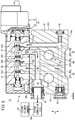
FIG. 4 is a first longitudinal cross-sectional view taken along line IV-IV ofFIG. 3 in the cylinder drive apparatus, when performing a return process of the fluid pressure cylinder; -
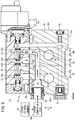
FIG. 5 is a second longitudinal cross-sectional view taken along line V-V ofFIG. 3 in the cylinder drive apparatus, when performing the return process of the fluid pressure cylinder; -
FIG. 6 is a third longitudinal cross-sectional view taken along line VI-VI ofFIG. 3 in the cylinder drive apparatus, when performing the return process of the fluid pressure cylinder; -
FIG. 7 is a schematic view with partial omission showing a state in which a switching valve ofFIG. 1 is switched from a second position to a first position; -
FIG. 8 is a first longitudinal cross-sectional view of the cylinder drive apparatus when a fluid pressure cylinder driving process is performed; -
FIG. 9 is a second longitudinal cross-sectional view of the cylinder drive apparatus when the fluid pressure cylinder driving process is performed; and -
FIG. 10 is a third longitudinal cross-sectional view of the cylinder drive apparatus when the fluid pressure cylinder driving process is performed. - Preferred embodiments of a cylinder drive manifold device and a cylinder drive apparatus according to the present invention will be presented and described in detail below with reference to the accompanying drawings.
- As shown in
FIG. 1 , acylinder drive apparatus 12 according to an embodiment of the present invention serves as an apparatus for driving a plurality offluid pressure cylinders 14. Each of thefluid pressure cylinders 14 is configured in the form of an air cylinder, for example, and includes apiston 22 that partitions the interior of acylinder unit 16 into afirst cylinder chamber 18 and asecond cylinder chamber 20 and that is capable of sliding reciprocally in the interior of thecylinder unit 16 under the action of a fluid pressure. One end of apiston rod 24 is connected to thepiston 22 and the other end thereof extends from thecylinder unit 16 to the exterior. - The
fluid pressure cylinders 14 perform work such as positioning of non-illustrated workpieces or the like at times that thepiston rods 24 are pushed out (expanded), and do not perform work at times that thepiston rods 24 are retracted. Thefirst cylinder chambers 18 are driving pressure chambers (head side cylinder chambers) located on an opposite side from thepiston rods 24, and thesecond cylinder chambers 20 are return side pressure chambers (rod side cylinder chambers) located on the side of thepiston rods 24. - As shown in
FIGS. 1 to 6 , thecylinder drive apparatus 12 comprises afluid supply source 26, a cylinder drive manifold device (hereinafter referred to as a "manifold device 10"), and a plurality ofswitching valves 28. Thefluid supply source 26 supplies a high-pressure fluid, and is configured, for example, in the form of an air compressor (seeFIG. 1 ). - The
manifold device 10 is equipped with a single block-shaped manifold 30 to which the plurality ofswitching valves 28 can be connected, and a plurality ofcheck valves 32 and a plurality ofthrottle valves 34 that are incorporated in themanifold 30. Theswitching valves 28, thecheck valves 32, and thethrottle valves 34 are provided respectively in the same number as the number of thefluid pressure cylinders 14. Although in the example shown inFIGS. 2A and 2B , five each of theswitching valves 28, thecheck valves 32, and thethrottle valves 34 are provided, the number of these valve members and thefluid pressure cylinders 14 can be arbitrarily changed. - As shown in
FIG. 2A to FIG. 6 , themanifold 30 is integrally formed in a block shape, for example, from a metal material such as aluminum or the like. However, the constituent material of themanifold 30 is not limited to being a metal material, and any arbitrary material such as a hard resin or the like can be adopted therefor. - The
manifold 30 is configured in the shape of a rectangular parallelepiped. More specifically, the manifold 30 includes a firstouter surface 30a, a secondouter surface 30b, a thirdouter surface 30c, a fourthouter surface 30d, a fifthouter surface 30e, and a sixthouter surface 30f. The firstouter surface 30a and the secondouter surface 30b are spaced apart from each other in a height direction (the direction of the arrow A) of the manifold 30. The firstouter surface 30a is an installation surface that is placed in contact with a fixing platform (not shown) when the manifold 30 is installed on the fixing platform. The secondouter surface 30b is located on a rear side of the firstouter surface 30a, and is a mounting surface (mounting site) on which the plurality of switchingvalves 28 can be mounted. The thirdouter surface 30c and the fourthouter surface 30d are side surfaces that are separated from each other in a longitudinal direction (the direction of the arrow B) of the manifold 30. The fifthouter surface 30e and the sixthouter surface 30f are side surfaces that are separated from each other in a lateral direction (the direction of the arrow C) of the manifold 30. - As shown in
FIGS. 3 to 6 , in the manifold 30, a plurality of holes are formed through which the fluid that is used for driving the plurality offluid pressure cylinders 14 flows. More specifically, onesupply port 36, onedischarge port 38, a plurality ofintroduction ports 40, a plurality offirst connection ports 42, a plurality ofsecond connection ports 44, a plurality ofthird connection ports 46, and a plurality of lead-outports 48 are formed in themanifold 30. Moreover, theintroduction ports 40, thefirst connection ports 42, thesecond connection ports 44, and thethird connection ports 46 are provided respectively in the same number as the number of the switchingvalves 28. - As shown in
FIG. 3 , thesupply port 36 is a hole (passage) which communicates with each of theintroduction ports 40, and through which the fluid from thefluid supply source 26 is supplied (seeFIG. 4 ). Thesupply port 36 is a through hole that extends linearly along the direction of the arrow B, and opens on each of the thirdouter surface 30c and the fourthouter surface 30d. A blockingmember 51 is provided in an end of thesupply port 36 on the side of the thirdouter surface 30c. Aconnector 52, which is provided in order to connect asupply pipe 50 that is connected to thefluid supply source 26, is attached to an opening of thesupply port 36 on the side of the fourthouter surface 30d (seeFIG. 1 ). In this case, because thesupply pipe 50 is connected via theconnector 52 only to the opening on one side of thesupply port 36, in comparison with a case in which thesupply pipe 50 is connected via theconnectors 52 to openings on both sides of thesupply port 36, the number of parts (a portion of thesupply pipe 50 and the connector 52) can be reduced. However, in accordance with specifications of thefluid pressure cylinders 14 and thecylinder drive apparatus 12, thesupply pipe 50 may be connected via theconnectors 52 to the openings on both sides of thesupply port 36, so as to increase the amount of fluid that is supplied to thesupply port 36. - The
discharge port 38 is a hole (passage) that communicates with each of the lead-outports 48, and discharges the fluid to the exterior of the manifold 30. Thedischarge port 38 is a through hole that extends linearly along the direction of the arrow B, and opens on each of the thirdouter surface 30c and the fourthouter surface 30d. A blockingmember 54 is provided in an end of thedischarge port 38 on the side of the thirdouter surface 30c. Asingle silencer 56 is provided in an end of thedischarge port 38 on the side of the fourthouter surface 30d in order to reduce the discharge noise (exhaust noise) of the fluid. An opening of thedischarge port 38 on the side of the fourthouter surface 30d functions as a discharge outlet 58 (seeFIG. 1 ). Thesupply port 36 and thedischarge port 38 are disposed alongside one another in the direction of the arrow C. However, in accordance with specifications of thefluid pressure cylinder 14 and thecylinder drive apparatus 12, the blockingmember 54 may be omitted, and thesilencers 56 may be provided in openings on both sides of thedischarge port 38. In this case, the fluid inside thedischarge port 38 can be discharged more smoothly to the exterior of the manifold 30. - As shown in
FIG. 4 , theintroduction ports 40 are holes (passages) for guiding the fluid to the switchingvalves 28. Theintroduction ports 40 extend linearly along the direction of the arrow A from thesupply port 36 to the secondouter surface 30b. - The
first connection ports 42 are holes (passages) for enabling mutual communication between the switchingvalves 28 and thefirst cylinder chambers 18 of thefluid pressure cylinders 14. Thefirst connection ports 42 open on the secondouter surface 30b and the fifthouter surface 30e. More specifically, thefirst connection ports 42 includefirst holes 42a andsecond holes 42b. Thefirst holes 42a extend linearly along the direction of the arrow C from the fifthouter surface 30e toward the sixthouter surface 30f to a position slightly shifted to the side of the fifthouter surface 30e from the center in the widthwise direction of the manifold 30. Thefirst holes 42a are positioned more closely to the side of the firstouter surface 30a than thesupply port 36 and thedischarge port 38. Thesecond holes 42b extend along the direction of the arrow A to the secondouter surface 30b from ends of thefirst holes 42a on the side of the sixthouter surface 30f. Thesecond holes 42b are positioned between thesupply port 36 and thedischarge port 38. Connectors 62 (seeFIG. 1 ), to whichfirst connection pipes 60 communicating with thefirst cylinder chambers 18 of thefluid pressure cylinders 14 can be connected, are provided in openings of thefirst connection ports 42 in thefirst holes 42a, with respect to the fifthouter surface 30e. - As shown in
FIG. 5 , thesecond connection ports 44 are holes (passages) for enabling mutual communication between the switchingvalves 28 and thesecond cylinder chambers 20 of thefluid pressure cylinders 14. Thesecond connection ports 44 includethird holes 44a andfourth holes 44b. Thethird holes 44a extend linearly along the direction of the arrow C from the fifthouter surface 30e toward the sixthouter surface 30f to a position slightly shifted to the side of the sixthouter surface 30f from the center in the widthwise direction of the manifold 30. - The
fourth holes 44b extend linearly along the direction of the arrow A to the secondouter surface 30b from ends of thethird holes 44a on the side of the sixthouter surface 30f. Openings of thesecond connection ports 44 with respect to the fifthouter surface 30e are positioned more closely to the side of the secondouter surface 30b (on the side of the switching valves 28) than the openings of thefirst connection ports 42 with respect to the fifthouter surface 30e. Connectors 66 (seeFIG. 1 ), to whichsecond connection pipes 64 communicating with thesecond cylinder chambers 20 of thefluid pressure cylinders 14 can be connected, are provided in openings of thesecond connection ports 44 in thethird holes 44a, with respect to the fifthouter surface 30e. - As shown in
FIG. 1 ,tanks 68 are provided in thesecond connection pipes 64. Thetanks 68 accumulate the fluid that is supplied from thefirst cylinder chambers 18 toward thesecond cylinder chambers 20, and are configured in the form of air tanks. By providing thetanks 68, the volumetric capacity of thesecond cylinder chambers 20 can be substantially increased. - As shown in
FIG. 4 , thethird connection ports 46 are holes (passages) for mutually connecting the switchingvalves 28 and thefirst connection ports 42. Thethird connection ports 46 includefifth holes 46a andsixth holes 46b. Thefifth holes 46a extend linearly along the direction of the arrow C to the secondouter surface 30b from ends of thefirst holes 42a on the side of the sixthouter surface 30f. Thesixth holes 46b extend linearly along the direction of the arrow A from thefifth holes 46a to the secondouter surface 30b. - In the
fifth holes 46a of thethird connection ports 46, thecheck valves 32 are provided which allow flow of the fluid in a direction from thefirst holes 42a of thefirst connection ports 42 toward the switchingvalves 28, and which prevent flow of the fluid in a direction from the switchingvalves 28 toward thefirst connection ports 42. In thefirst holes 42a of thefirst connection ports 42 and thefifth holes 46a of thethird connection ports 46, fluid flow paths to thecheck valves 32 from openings in thefirst holes 42a with respect to the fifthouter surface 30e are formed so as to extend linearly along the direction of the arrow C. - As shown in
FIG. 6 , the lead-outports 48 are holes (passages) in which the fluid from therespective switching valves 28 is guided. The lead-outports 48 extend from the secondouter surface 30b to thedischarge port 38. More specifically, the lead-outports 48 include first lead-out holes 48a, second lead-outholes 48b, third lead-outholes 48c, and fourth lead-out holes 48d. The first lead-out holes 48a extend linearly along the direction of the arrow A from the secondouter surface 30b toward the firstouter surface 30a. The second lead-outholes 48b extend linearly along the direction of the arrow C from the first lead-out holes 48a to the sixthouter surface 30f. The second lead-outholes 48b are positioned more closely to the secondouter surface 30b than thefifth holes 46a of thethird connection ports 46. - The third lead-out
holes 48c extend linearly along the direction of the arrow A from the secondouter surface 30b toward the firstouter surface 30a so as to pass through the second lead-outholes 48b. Blockingmembers 67 which are made, for example, from steel balls or the like are disposed in an airtight manner within the third lead-outholes 48c, more on the side of the secondouter surface 30b than the second lead-outholes 48b. The fourth lead-out holes 48d extend linearly along the direction of the arrow C from ends of the third lead-outholes 48c on the side of the firstouter surface 30a. The fourth lead-out holes 48d open on the sixthouter surface 30f and on a wall surface that constitutes thedischarge port 38. Blockingmembers 69 which are made, for example, from steel balls or the like are disposed in an airtight manner within the fourth lead-out holes 48d, more on the side of the sixthouter surface 30f than the third lead-outholes 48c. - The
throttle valves 34 are disposed in the second lead-outholes 48b of the lead-outports 48. Thethrottle valves 34 are variable throttle valves which are disposed (on the side of the secondouter surface 30b) at a location on the manifold 30 that is closer to the mounting site for the plurality of switchingvalves 28 than thecheck valves 32. More specifically, thethrottle valves 34 are configured to be capable of changing the flow passage cross-sectional areas of the lead-outports 48. By rotating thethrottle valves 34 with a tool such as a flat-blade screwdriver, and thereby causing thethrottle valves 34 to be advanced or retracted, a user can change the flow passage cross-sectional areas of the lead-outports 48. - As shown in
FIGS. 4 to 6 , the respective openings of theintroduction ports 40, thefirst connection ports 42, the lead-outports 48, thesecond connection ports 44, and thethird connection ports 46 are positioned in this order along the direction of the arrow C, on the secondouter surface 30b of the manifold 30 on which the plurality of switchingvalves 28 are capable of being mounted. - As shown in
FIGS. 1 ,4 , and5 , the plurality of switchingvalves 28 alternately supply the fluid to thefirst cylinder chambers 18 and thesecond cylinder chambers 20 that are partitioned by thepistons 22 of the respectivefluid pressure cylinders 14. Each of the switchingvalves 28 is a so-called five-port pilot-type solenoid valve, and is equipped with a valvemain body 70, and apilot valve mechanism 72 disposed on the valvemain body 70. The valvemain body 70 includes abody 76 in which first tofifth ports 74a to 74e are formed, and aspool 80 that is displaceably disposed within avalve chamber 78 of thebody 76. - In the
body 76, thefirst port 74a, thesecond port 74b, thefifth port 74e, thethird port 74c, and thefourth port 74d are positioned in this order along the direction of the arrow C. Thefirst port 74a communicates with theintroduction port 40. Thesecond port 74b communicates with thesecond hole 42b of thefirst connection port 42. Thethird port 74c communicates with thefourth hole 44b of thesecond connection port 44. Thefourth port 74d communicates with thesixth hole 46b of thethird connection port 46. Thefifth port 74e communicates with the first lead-outhole 48a of the lead-outport 48. - The
spool 80 includes first to fourthlarge diameter portions 82a to 82d. The firstlarge diameter portion 82a, by coming into contact with a wall surface constituting thevalve chamber 78, is capable of blocking communication between thefirst port 74a and thesecond port 74b. The secondlarge diameter portion 82b, by coming into contact with the wall surface constituting thevalve chamber 78, is capable of blocking communication between thesecond port 74b and thefifth port 74e. The thirdlarge diameter portion 82c, by coming into contact with the wall surface constituting thevalve chamber 78, is capable of blocking communication between thefifth port 74e and thethird port 74c. The fourthlarge diameter portion 82d, by coming into contact with the wall surface constituting thevalve chamber 78, is capable of blocking communication between thethird port 74c and thefourth port 74d. - Stated otherwise, by causing the
spool 80 to be displaced, the switchingvalve 28 can switch between a state of communication and a state of blockage, respectively, between theintroduction port 40 and thefirst connection port 42, between thefirst connection port 42 and the lead-outport 48, between the lead-outport 48 and thesecond connection port 44, and between thesecond connection port 44 and thethird connection port 46. - More specifically, as shown in
FIGS. 7 to 9 , at a first position of the switchingvalve 28, theintroduction port 40 and thefirst connection port 42 are in mutual communication with each other, and the lead-outport 48 and thesecond connection port 44 are in mutual communication with each other. Further, in the first position, communication between thefirst connection port 42 and the lead-outport 48 is blocked, and communication between thesecond connection port 44 and thethird connection port 46 is blocked. - As shown in
FIGS. 1 ,4 , and5 , at a second position of the switchingvalve 28, thefirst connection port 42 and the lead-outport 48 are in mutual communication with each other, and thesecond connection port 44 and thethird connection port 46 are in mutual communication with each other. Further, in the second position, communication between theintroduction port 40 and thefirst connection port 42 is blocked, and communication between the lead-outport 48 and thesecond connection port 44 is blocked. - At a time of non-energization, the switching
valves 28 are maintained in the second position by a biasing force of the springs 84 (seeFIG. 1 ), and when energized, are switched from the second position to the first position under the action of thepilot valve mechanisms 72. Moreover, energization of the switchingvalves 28 is performed by outputting energization commands to the switchingvalves 28 from a non-illustrated PLC (Programmable Logic Controller) which is a higher-order device. Non-energization of the switchingvalves 28 is performed by outputting non-energization commands from the PLC to the switchingvalves 28. - The
cylinder drive apparatus 12 according to the present embodiment is configured basically in the manner described above. Next, operations (a method of usage) thereof will be described. In an initial state, as shown inFIG. 1 , thepistons 22 of thefluid pressure cylinders 14 are located at a stroke end position on an opposite side from thepiston rods 24, and the switchingvalves 28 are placed in the second position. - In the
cylinder drive apparatus 12, in the case that a driving process is performed to cause thepiston rods 24 to be extended, the switchingvalves 28 are switched from the second position to the first position as shown inFIG. 7 . Upon doing so, as shown inFIGS. 3 and8 , the high-pressure fluid (compressed air), which is guided from thefluid supply source 26 to thesupply port 36 via thesupply pipe 50, branches into the plurality ofintroduction ports 40. Then, as shown InFIG. 8 , the fluid that has branched into therespective introduction ports 40 flows into thefirst cylinder chambers 18 of the respectivefluid pressure cylinders 14 via thefirst ports 74a, thesecond ports 74b, thefirst connection ports 42, and thefirst connection pipes 60. Consequently, thepistons 22 are displaced to the side of thepiston rods 24, and thepiston rods 24 are extended. At this time, since communication between thesecond connection ports 44 and thethird connection ports 46 is blocked by the switchingvalves 28, the fluid from thefluid supply source 26 is efficiently supplied into thefirst cylinder chambers 18. - Further, as shown in
FIGS. 9 and10 , the fluid in thesecond cylinder chambers 20 of the respectivefluid pressure cylinders 14 flows into thedischarge port 38 after being guided to the lead-outports 48 via the second connection pipes 64 (and the tanks 68), thesecond connection ports 44, thethird ports 74c, and thefifth ports 74e (refer toFIGS. 7 ,9 , and10 ), and having passed through thethrottle valves 34. Then, the fluid that has flowed into thedischarge port 38 from the plurality of lead-outports 48 passes through thesilencer 56, and is discharged from thedischarge outlet 58 into the atmosphere (seeFIG. 3 ). - Next, in the case that a return process is performed to retract the
piston rods 24, the switchingvalves 28 are switched from the first position to the second position as shown inFIG. 1 . Upon doing so, the supply of fluid from thefluid supply source 26 into thefirst cylinder chambers 18 is stopped. Then, as shown inFIGS. 4 and6 , the fluid in thefirst cylinder chambers 18 is guided to thefirst connection pipes 60 and thefirst holes 42a of thefirst connection ports 42, and branches into thesecond holes 42b and thethird connection ports 46. The fluid that has flowed into thesecond holes 42b flows into thedischarge port 38 after being guided to the lead-outports 48 via thesecond ports 74b and thefifth ports 74e, and having passed through thethrottle valves 34. - As shown in
FIGS. 4 and5 , the fluid that has flowed into thethird connection ports 46 flows into thesecond cylinder chambers 20 via thefourth ports 74d, thethird ports 74c, thesecond connection ports 44, and thesecond connection pipes 64. Moreover, by changing the throttle openings (flow passage cross-sectional area) of thethrottle valves 34, the ratio between the flow rate of the fluid that is guided from thefirst holes 42a to thethird connection ports 46, and the flow rate of the fluid that is guided from thefirst holes 42a to thesecond holes 42b is adjusted. When the fluid flows into thesecond cylinder chambers 20, thepistons 22 are displaced to the side opposite from thepiston rods 24, and thepiston rods 24 are retracted. - In the return process, the
pistons 22 are displaced using the fluid that is discharged from thefirst cylinder chambers 18. Therefore, there is no need to supply fluid from thefluid supply source 26 into thesecond cylinder chambers 20, and the power consumption and the air consumption amount of thefluid supply source 26 can be suppressed, whereby it is possible to achieve a saving of energy of thecylinder drive apparatus 12. - Next, advantages and effects of the present embodiment will be described below.
- The
manifold device 10 that constitutes thecylinder drive apparatus 12 serves as a device for driving the plurality offluid pressure cylinders 14. Themanifold device 10 is equipped with the block-shapedmanifold 30 in which a plurality of holes (thesupply port 36, thedischarge port 38, theintroduction ports 40, thefirst connection ports 42, thesecond connection ports 44, thethird connection ports 46, and the lead-out ports 48) are formed through which the fluid used to drive the plurality offluid pressure cylinders 14 flows. The manifold 30 is configured to enable the plurality of switchingvalves 28 to be mounted thereon, the switching valves being configured to alternately supply the fluid to thefirst cylinder chambers 18 and thesecond cylinder chambers 20 which are partitioned by thepistons 22 of the respectivefluid pressure cylinders 14. The plurality ofcheck valves 32 and the plurality ofthrottle valves 34 are incorporated in the plurality of holes of the manifold 30. - In this manner, in the
manifold device 10, since the plurality ofcheck valves 32 are incorporated in the plurality of holes of the manifold 30, piping for the purpose of connecting the switchingvalves 28 and thecheck valves 32 to each other is rendered unnecessary. Further, since the plurality ofthrottle valves 34 are incorporated in the plurality of holes of the manifold 30, piping for the purpose of connecting the switchingvalves 28 and thethrottle valves 34 to each other is rendered unnecessary. Accordingly, it is possible to reduce the number of parts of the cylinderdrive manifold device 10, together with making it easy to perform the assembly operation. - The plurality of holes of the manifold 30 include the plurality of
introduction ports 40 through which the fluid is introduced into therespective switching valves 28, the plurality of lead-outports 48 through which the fluid is guided from therespective switching valves 28, the plurality offirst connection ports 42 which enable mutual communication between therespective switching valves 28 and thefirst cylinder chambers 18 of the respectivefluid pressure cylinders 14, the plurality ofsecond connection ports 44 which enable mutual communication between therespective switching valves 28 and thesecond cylinder chambers 20 of the respectivefluid pressure cylinders 14, and the plurality ofthird connection ports 46 that connect thefirst connection ports 42 and the switchingvalves 28 to each other. - In each of the
third connection ports 46, thecheck valve 32 is provided which allows flow of the fluid in a direction from thefirst connection port 42 toward the switchingvalve 28, and which prevents flow of the fluid in a direction from the switchingvalve 28 toward thefirst connection port 42. Thethrottle valves 34 are provided in the respective lead-outports 48. - Each of the switching
valves 28 is capable of switching between a state of communication and a state of blockage, respectively, between theintroduction port 40 and thefirst connection port 42, between thefirst connection port 42 and the lead-outport 48, between the lead-outport 48 and thesecond connection port 44, and between thesecond connection port 44 and thethird connection port 46. - In the first position of the switching
valves 28, theintroduction port 40 and thefirst connection port 42 communicate with each other, and the lead-outport 48 and thesecond connection port 44 communicate with each other, while communication between thefirst connection port 42 and the lead-outport 48 is blocked, and communication between thesecond connection port 44 and thethird connection port 46 is blocked (refer toFIG. 8 ). - In the second position of the switching
valves 28, thefirst connection port 42 and the lead-outport 48 communicate with each other, and thesecond connection port 44 and thethird connection port 46 communicate with each other, while communication between theintroduction port 40 and thefirst connection port 42 is blocked, and communication between the lead-outport 48 and thesecond connection port 44 is blocked (refer toFIG. 4 ). - In this case, in the second position of the switching
valves 28, the fluid inside thefirst cylinder chamber 18 of thefluid pressure cylinder 14 is supplied to thesecond cylinder chamber 20 and simultaneously discharged to the lead-outport 48 via thefirst connection port 42, thethird connection port 46, and the second connection port 44 (seeFIGS. 4 to 6 ). Consequently, the fluid pressure in thesecond cylinder chamber 20 increases and the fluid pressure in thefirst cylinder chamber 18 rapidly decreases, and therefore, it is possible to reduce the amount of fluid that is consumed in order to drive thefluid pressure cylinder 14. Therefore, it is possible to achieve a saving of energy when the plurality offluid pressure cylinders 14 are driven. - In each of the
first connection ports 42 and each of thethird connection ports 46, a fluid flow path is formed so as to extend linearly to thecheck valve 32 from an opening of thefirst connection port 42 in which theconnector 62 can be mounted to which a pipe communicating with thefirst cylinder chamber 18 can be connected. - In accordance with this feature, in comparison with a case in which the fluid flow path from the opening of the
first connection port 42 to thecheck valve 32 is bent, frictional resistance between the fluid and the wall surface of the flow path can be reduced. Thus, the fluid inside thefirst cylinder chamber 18 can be efficiently guided into thesecond cylinder chamber 20. - The
respective throttle valves 34 are variable throttle valves which are disposed at a location on the manifold 30 that is closer to a mounting site for the plurality of switchingvalves 28 than therespective check valves 32. Therefore, the length of the flow paths from the switchingvalves 28 to thethrottle valves 34 can be made comparatively short. More specifically, the volume of fluid from the switchingvalves 28 to thethrottle valves 34 can be made comparatively small. Therefore, the flow rate (the pressure) of the fluid that is guided from thefirst connection ports 42 to thethird connection ports 46 can be easily adjusted by changing the throttle opening of thethrottle valves 34. - A
single supply port 36, which communicates with each of theintroduction ports 40 and to which the fluid from thefluid supply source 26 is supplied, is formed in themanifold 30. In accordance with this feature, even in the case that a plurality of thefluid pressure cylinders 14 are driven, the number of pipes provided in order to connect thefluid supply source 26 and the manifold 30 can be reduced. - A
single discharge port 38, which communicates with each of the lead-outports 48 and is configured to discharge the fluid to the exterior of the manifold 30, is formed in themanifold 30. In addition, asingle silencer 56 configured to reduce discharge noise of the fluid is disposed in thedischarge port 38. Therefore, even in the case that a plurality of thefluid pressure cylinders 14 are driven, only onesilencer 56 is used. - The cylinder drive manifold device and the cylinder drive apparatus according to the present invention are not limited to those in the embodiments described above. It is a matter of course that various modified or additional structures could be adopted therein without deviating from the essence and gist of the invention.
Claims (7)
- A cylinder drive manifold device (10) configured to drive a plurality of fluid pressure cylinders (14), the cylinder drive manifold device (10) comprising:a block-shaped manifold (30) in which a plurality of holes are formed through which a fluid used to drive the plurality of fluid pressure cylinders (14) flows,wherein the manifold (30) is configured to enable a plurality of switching valves (28) to be mounted thereon, the switching valves being configured to alternately supply the fluid to a first cylinder chamber (18) and a second cylinder chamber (20) partitioned by a piston (22) of each of the fluid pressure cylinders (14), anda plurality of check valves (32) and a plurality of throttle valves (34) are incorporated in the plurality of holes of the manifold (30).
- The cylinder drive manifold device (10) according to claim 1, wherein the plurality of holes of the manifold (30) include:a plurality of introduction ports (40) configured to introduce the fluid into the respective switching valves (28) ;a plurality of lead-out ports (48) through which the fluid is guided from the respective switching valves (28);a plurality of first connection ports (42) configured to enable mutual communication between the respective switching valves (28) and the first cylinder chambers (18) of the respective fluid pressure cylinders (14);a plurality of second connection ports (44) configured to enable mutual communication between the respective switching valves (28) and the second cylinder chambers (20) of the respective fluid pressure cylinders (14); anda plurality of third connection ports (46) configured to connect the first connection ports (42) and the switching valves (28) to each other,wherein, in each of the third connection ports (46), the check valve (32) is provided which allows flow of the fluid in a direction from the first connection port (42) toward the switching valve (28), and which prevents flow of the fluid in a direction from the switching valve (28) toward the first connection port (42),the throttle valves (34) are provided in the respective lead-out ports (48),each of the switching valves (28) is configured to switch between a state of communication and a state of blockage, respectively, between the introduction port (40) and the first connection port (42), between the first connection port (42) and the lead-out port (48), between the lead-out port (48) and the second connection port (44), and between the second connection port (44) and the third connection port (46),in a first position of the switching valves (28), the introduction port (40) and the first connection port (42) communicate with each other, and the lead-out port (48) and the second connection port (44) communicate with each other, while communication between the first connection port (42) and the lead-out port (48) is blocked, and communication between the second connection port (44) and the third connection port (46) is blocked, andin a second position of the switching valves (28), the first connection port (42) and the lead-out port (48) communicate with each other, and the second connection port (44) and the third connection port (46) communicate with each other, while communication between the introduction port (40) and the first connection port (42) is blocked, and communication between the lead-out port (48) and the second connection port (44) is blocked.
- The cylinder drive manifold device (10) according to claim 2, wherein, in each of the first connection ports (42) and each of the third connection ports (46), a fluid flow path is formed so as to extend linearly to the check valve (32) from an opening of the first connection port (42) in which a connector (62), to which a pipe (60) communicating with the first cylinder chamber (18) is connectable, is configured to be mounted.
- The cylinder drive manifold device (10) according to claim 2, wherein the respective throttle valves (34) are variable throttle valves (34) which are disposed at a location on the manifold (30) that is closer to a mounting site (30b) for the plurality of switching valves (28) than the respective check valves (32).
- The cylinder drive manifold device (10) according to claim 2, wherein a single supply port (36), which communicates with each of the introduction ports (40) and to which the fluid from a fluid supply source (26) is supplied, is formed in the manifold (30).
- The cylinder drive manifold device (10) according to claim 2, wherein
a single discharge port (38), which communicates with each of the lead-out ports (48) and is configured to discharge the fluid to an exterior of the manifold (30), is formed in the manifold (30), and
a single silencer (56) configured to reduce discharge noise of the fluid is disposed in the discharge port (38). - A cylinder drive apparatus (12) comprising:the cylinder drive manifold device (10) according to any one of claims 1 to 6; anda plurality of the switching valves (28).
Applications Claiming Priority (2)
| Application Number | Priority Date | Filing Date | Title |
|---|---|---|---|
| JP2017098128A JP6684480B2 (en) | 2017-05-17 | 2017-05-17 | Cylinder drive manifold device and cylinder drive device |
| PCT/JP2018/014058 WO2018211837A1 (en) | 2017-05-17 | 2018-04-02 | Cylinder drive manifold device and cylinder drive apparatus |
Publications (3)
| Publication Number | Publication Date |
|---|---|
| EP3627018A1 true EP3627018A1 (en) | 2020-03-25 |
| EP3627018A4 EP3627018A4 (en) | 2021-02-24 |
| EP3627018B1 EP3627018B1 (en) | 2022-12-21 |
Family
ID=64274155
Family Applications (1)
| Application Number | Title | Priority Date | Filing Date |
|---|---|---|---|
| EP18802075.4A Active EP3627018B1 (en) | 2017-05-17 | 2018-04-02 | Cylinder drive apparatus with a cylinder drive manifold device |
Country Status (10)
| Country | Link |
|---|---|
| US (1) | US11181127B2 (en) |
| EP (1) | EP3627018B1 (en) |
| JP (1) | JP6684480B2 (en) |
| KR (1) | KR102266451B1 (en) |
| CN (1) | CN110651145B (en) |
| BR (1) | BR112019023986A2 (en) |
| MX (1) | MX2019013588A (en) |
| RU (1) | RU2739850C9 (en) |
| TW (1) | TWI666388B (en) |
| WO (1) | WO2018211837A1 (en) |
Families Citing this family (5)
| Publication number | Priority date | Publication date | Assignee | Title |
|---|---|---|---|---|
| DE102019121433B4 (en) * | 2019-08-08 | 2022-12-29 | SMC Deutschland GmbH | Fluid return device for a double-acting cylinder and method of operating such a cylinder |
| TW202141165A (en) | 2020-03-27 | 2021-11-01 | 美商應用材料股份有限公司 | Extreme ultraviolet mask absorber materials |
| US11300871B2 (en) * | 2020-04-29 | 2022-04-12 | Applied Materials, Inc. | Extreme ultraviolet mask absorber materials |
| TW202202641A (en) | 2020-07-13 | 2022-01-16 | 美商應用材料股份有限公司 | Extreme ultraviolet mask absorber materials |
| WO2024119257A1 (en) * | 2022-12-08 | 2024-06-13 | Metal Técnica Bovenau Ltda | Hydraulic actuator with dual pneumatic actuation for use in hydraulic actuation for hydroelectric plants |
Family Cites Families (15)
| Publication number | Priority date | Publication date | Assignee | Title |
|---|---|---|---|---|
| JPH0743447Y2 (en) * | 1988-10-14 | 1995-10-09 | 株式会社巴技術研究所 | Valve operating speed controller |
| JPH02118202A (en) * | 1988-10-27 | 1990-05-02 | Nippon Pneumatic Mfg Co Ltd | Branch circuit unit |
| DE4232628A1 (en) * | 1992-09-29 | 1994-03-31 | Herion Werke Kg | Directional control valve |
| JPH10132104A (en) * | 1996-10-28 | 1998-05-22 | Smc Corp | Pilot type three port directional control valve |
| JP3705730B2 (en) | 2000-04-28 | 2005-10-12 | Smc株式会社 | Pneumatic cylinder exhaust recovery device |
| DE10252592A1 (en) | 2001-11-12 | 2003-06-18 | Otto Herman Seyfarth | Electropneumatic installation has integrated pneumatic distribution part in form of single block with several differently oriented internal channels arranged in three dimensions |
| KR100522056B1 (en) | 2002-03-15 | 2005-10-18 | 김명환 | Servo Actuator Manifold |
| US6890200B1 (en) * | 2003-12-04 | 2005-05-10 | Hon Hai Precision Ind. Co., Ltd. | Floatable panel mount cable assembly |
| JP4378627B2 (en) * | 2004-03-30 | 2009-12-09 | Smc株式会社 | Air servo cylinder |
| DE202005016766U1 (en) * | 2005-10-26 | 2006-01-12 | Festo Ag & Co. | valve battery |
| CN101828043A (en) * | 2007-09-21 | 2010-09-08 | 加拿大斯奈邦工具有限公司 | System and apparatus to synchronize a plurality of hydraulically actuated components |
| US8356630B2 (en) * | 2008-06-02 | 2013-01-22 | Eaton Corporation | Valve damping system |
| WO2013065530A1 (en) * | 2011-11-02 | 2013-05-10 | Smc株式会社 | Flow rate control device |
| JP2013104518A (en) * | 2011-11-16 | 2013-05-30 | Kawasaki Heavy Ind Ltd | Cushion valve device and multi-cushion valve unit with same |
| RU141437U8 (en) * | 2013-03-22 | 2014-09-20 | Общество с ограниченной ответственностью "Браво Моторс" | TRANSFORMATION HYDROCYLINDER |
-
2017
- 2017-05-17 JP JP2017098128A patent/JP6684480B2/en active Active
-
2018
- 2018-04-02 CN CN201880032631.8A patent/CN110651145B/en active Active
- 2018-04-02 EP EP18802075.4A patent/EP3627018B1/en active Active
- 2018-04-02 RU RU2019141810A patent/RU2739850C9/en active
- 2018-04-02 US US16/614,194 patent/US11181127B2/en active Active
- 2018-04-02 BR BR112019023986A patent/BR112019023986A2/en not_active IP Right Cessation
- 2018-04-02 KR KR1020197037119A patent/KR102266451B1/en active Active
- 2018-04-02 WO PCT/JP2018/014058 patent/WO2018211837A1/en not_active Ceased
- 2018-04-02 MX MX2019013588A patent/MX2019013588A/en unknown
- 2018-04-10 TW TW107112259A patent/TWI666388B/en not_active IP Right Cessation
Also Published As
| Publication number | Publication date |
|---|---|
| RU2739850C9 (en) | 2021-10-26 |
| BR112019023986A2 (en) | 2020-06-09 |
| TWI666388B (en) | 2019-07-21 |
| JP2018194083A (en) | 2018-12-06 |
| KR20200007041A (en) | 2020-01-21 |
| CN110651145B (en) | 2021-07-16 |
| TW201901041A (en) | 2019-01-01 |
| US11181127B2 (en) | 2021-11-23 |
| EP3627018B1 (en) | 2022-12-21 |
| KR102266451B1 (en) | 2021-06-17 |
| JP6684480B2 (en) | 2020-04-22 |
| EP3627018A4 (en) | 2021-02-24 |
| US20200149560A1 (en) | 2020-05-14 |
| WO2018211837A1 (en) | 2018-11-22 |
| CN110651145A (en) | 2020-01-03 |
| RU2739850C1 (en) | 2020-12-29 |
| MX2019013588A (en) | 2020-01-13 |
Similar Documents
| Publication | Publication Date | Title |
|---|---|---|
| EP3627018B1 (en) | Cylinder drive apparatus with a cylinder drive manifold device | |
| KR102601408B1 (en) | spool valve | |
| KR102175356B1 (en) | Hydraulic cylinder | |
| KR20210013146A (en) | Fluid pressure cylinder drive method and drive device | |
| CN112096683B (en) | Integrated pumping main valve | |
| US11933328B2 (en) | Cylinder drive device and flow channel unit | |
| CN112703323A (en) | Fluid pressure cylinder | |
| CN101542173B (en) | Exhaust venting for a fluid control device | |
| CN111852972B (en) | Integrated mortar pump control valve | |
| WO2007117099A1 (en) | Hydraulic pressure transformers | |
| JP6345013B2 (en) | Pneumatic cylinder device | |
| US9670921B2 (en) | Reciprocating drive mechanism with a spool vent | |
| KR20140114549A (en) | Piston Pump | |
| KR20160115365A (en) | Open and close of the valve apparatus by using the air pressure | |
| KR101411234B1 (en) | Reciprocatable double acting booster and Operating method thereof | |
| CA2997814C (en) | Reciprocating drive mechanism with a spool vent | |
| WO2015181444A1 (en) | Valve | |
| CN119802039A (en) | Cylinder device | |
| JP2006336857A (en) | Cylinder |
Legal Events
| Date | Code | Title | Description |
|---|---|---|---|
| STAA | Information on the status of an ep patent application or granted ep patent |
Free format text: STATUS: THE INTERNATIONAL PUBLICATION HAS BEEN MADE |
|
| PUAI | Public reference made under article 153(3) epc to a published international application that has entered the european phase |
Free format text: ORIGINAL CODE: 0009012 |
|
| STAA | Information on the status of an ep patent application or granted ep patent |
Free format text: STATUS: REQUEST FOR EXAMINATION WAS MADE |
|
| 17P | Request for examination filed |
Effective date: 20191213 |
|
| AK | Designated contracting states |
Kind code of ref document: A1 Designated state(s): AL AT BE BG CH CY CZ DE DK EE ES FI FR GB GR HR HU IE IS IT LI LT LU LV MC MK MT NL NO PL PT RO RS SE SI SK SM TR |
|
| AX | Request for extension of the european patent |
Extension state: BA ME |
|
| DAV | Request for validation of the european patent (deleted) | ||
| DAX | Request for extension of the european patent (deleted) | ||
| A4 | Supplementary search report drawn up and despatched |
Effective date: 20210122 |
|
| RIC1 | Information provided on ipc code assigned before grant |
Ipc: F15B 11/06 20060101ALI20210118BHEP Ipc: F15B 11/024 20060101ALI20210118BHEP Ipc: F15B 13/08 20060101ALI20210118BHEP Ipc: F15B 11/00 20060101ALI20210118BHEP Ipc: F16K 27/00 20060101AFI20210118BHEP Ipc: F15B 13/02 20060101ALI20210118BHEP Ipc: F15B 11/064 20060101ALI20210118BHEP |
|
| GRAP | Despatch of communication of intention to grant a patent |
Free format text: ORIGINAL CODE: EPIDOSNIGR1 |
|
| STAA | Information on the status of an ep patent application or granted ep patent |
Free format text: STATUS: GRANT OF PATENT IS INTENDED |
|
| INTG | Intention to grant announced |
Effective date: 20220520 |
|
| GRAS | Grant fee paid |
Free format text: ORIGINAL CODE: EPIDOSNIGR3 |
|
| GRAJ | Information related to disapproval of communication of intention to grant by the applicant or resumption of examination proceedings by the epo deleted |
Free format text: ORIGINAL CODE: EPIDOSDIGR1 |
|
| GRAL | Information related to payment of fee for publishing/printing deleted |
Free format text: ORIGINAL CODE: EPIDOSDIGR3 |
|
| STAA | Information on the status of an ep patent application or granted ep patent |
Free format text: STATUS: REQUEST FOR EXAMINATION WAS MADE |
|
| INTC | Intention to grant announced (deleted) | ||
| GRAP | Despatch of communication of intention to grant a patent |
Free format text: ORIGINAL CODE: EPIDOSNIGR1 |
|
| STAA | Information on the status of an ep patent application or granted ep patent |
Free format text: STATUS: GRANT OF PATENT IS INTENDED |
|
| INTG | Intention to grant announced |
Effective date: 20220909 |
|
| GRAA | (expected) grant |
Free format text: ORIGINAL CODE: 0009210 |
|
| STAA | Information on the status of an ep patent application or granted ep patent |
Free format text: STATUS: THE PATENT HAS BEEN GRANTED |
|
| AK | Designated contracting states |
Kind code of ref document: B1 Designated state(s): AL AT BE BG CH CY CZ DE DK EE ES FI FR GB GR HR HU IE IS IT LI LT LU LV MC MK MT NL NO PL PT RO RS SE SI SK SM TR |
|
| REG | Reference to a national code |
Ref country code: GB Ref legal event code: FG4D |
|
| REG | Reference to a national code |
Ref country code: CH Ref legal event code: EP |
|
| REG | Reference to a national code |
Ref country code: DE Ref legal event code: R096 Ref document number: 602018044557 Country of ref document: DE |
|
| REG | Reference to a national code |
Ref country code: AT Ref legal event code: REF Ref document number: 1539246 Country of ref document: AT Kind code of ref document: T Effective date: 20230115 |
|
| REG | Reference to a national code |
Ref country code: IE Ref legal event code: FG4D |
|
| REG | Reference to a national code |
Ref country code: LT Ref legal event code: MG9D |
|
| REG | Reference to a national code |
Ref country code: NL Ref legal event code: MP Effective date: 20221221 |
|
| PG25 | Lapsed in a contracting state [announced via postgrant information from national office to epo] |
Ref country code: SE Free format text: LAPSE BECAUSE OF FAILURE TO SUBMIT A TRANSLATION OF THE DESCRIPTION OR TO PAY THE FEE WITHIN THE PRESCRIBED TIME-LIMIT Effective date: 20221221 Ref country code: NO Free format text: LAPSE BECAUSE OF FAILURE TO SUBMIT A TRANSLATION OF THE DESCRIPTION OR TO PAY THE FEE WITHIN THE PRESCRIBED TIME-LIMIT Effective date: 20230321 Ref country code: LT Free format text: LAPSE BECAUSE OF FAILURE TO SUBMIT A TRANSLATION OF THE DESCRIPTION OR TO PAY THE FEE WITHIN THE PRESCRIBED TIME-LIMIT Effective date: 20221221 Ref country code: FI Free format text: LAPSE BECAUSE OF FAILURE TO SUBMIT A TRANSLATION OF THE DESCRIPTION OR TO PAY THE FEE WITHIN THE PRESCRIBED TIME-LIMIT Effective date: 20221221 |
|
| REG | Reference to a national code |
Ref country code: AT Ref legal event code: MK05 Ref document number: 1539246 Country of ref document: AT Kind code of ref document: T Effective date: 20221221 |
|
| PG25 | Lapsed in a contracting state [announced via postgrant information from national office to epo] |
Ref country code: RS Free format text: LAPSE BECAUSE OF FAILURE TO SUBMIT A TRANSLATION OF THE DESCRIPTION OR TO PAY THE FEE WITHIN THE PRESCRIBED TIME-LIMIT Effective date: 20221221 Ref country code: LV Free format text: LAPSE BECAUSE OF FAILURE TO SUBMIT A TRANSLATION OF THE DESCRIPTION OR TO PAY THE FEE WITHIN THE PRESCRIBED TIME-LIMIT Effective date: 20221221 Ref country code: HR Free format text: LAPSE BECAUSE OF FAILURE TO SUBMIT A TRANSLATION OF THE DESCRIPTION OR TO PAY THE FEE WITHIN THE PRESCRIBED TIME-LIMIT Effective date: 20221221 Ref country code: GR Free format text: LAPSE BECAUSE OF FAILURE TO SUBMIT A TRANSLATION OF THE DESCRIPTION OR TO PAY THE FEE WITHIN THE PRESCRIBED TIME-LIMIT Effective date: 20230322 |
|
| PG25 | Lapsed in a contracting state [announced via postgrant information from national office to epo] |
Ref country code: NL Free format text: LAPSE BECAUSE OF FAILURE TO SUBMIT A TRANSLATION OF THE DESCRIPTION OR TO PAY THE FEE WITHIN THE PRESCRIBED TIME-LIMIT Effective date: 20221221 |
|
| PG25 | Lapsed in a contracting state [announced via postgrant information from national office to epo] |
Ref country code: SM Free format text: LAPSE BECAUSE OF FAILURE TO SUBMIT A TRANSLATION OF THE DESCRIPTION OR TO PAY THE FEE WITHIN THE PRESCRIBED TIME-LIMIT Effective date: 20221221 Ref country code: RO Free format text: LAPSE BECAUSE OF FAILURE TO SUBMIT A TRANSLATION OF THE DESCRIPTION OR TO PAY THE FEE WITHIN THE PRESCRIBED TIME-LIMIT Effective date: 20221221 Ref country code: PT Free format text: LAPSE BECAUSE OF FAILURE TO SUBMIT A TRANSLATION OF THE DESCRIPTION OR TO PAY THE FEE WITHIN THE PRESCRIBED TIME-LIMIT Effective date: 20230421 Ref country code: ES Free format text: LAPSE BECAUSE OF FAILURE TO SUBMIT A TRANSLATION OF THE DESCRIPTION OR TO PAY THE FEE WITHIN THE PRESCRIBED TIME-LIMIT Effective date: 20221221 Ref country code: EE Free format text: LAPSE BECAUSE OF FAILURE TO SUBMIT A TRANSLATION OF THE DESCRIPTION OR TO PAY THE FEE WITHIN THE PRESCRIBED TIME-LIMIT Effective date: 20221221 Ref country code: CZ Free format text: LAPSE BECAUSE OF FAILURE TO SUBMIT A TRANSLATION OF THE DESCRIPTION OR TO PAY THE FEE WITHIN THE PRESCRIBED TIME-LIMIT Effective date: 20221221 Ref country code: AT Free format text: LAPSE BECAUSE OF FAILURE TO SUBMIT A TRANSLATION OF THE DESCRIPTION OR TO PAY THE FEE WITHIN THE PRESCRIBED TIME-LIMIT Effective date: 20221221 |
|
| PG25 | Lapsed in a contracting state [announced via postgrant information from national office to epo] |
Ref country code: SK Free format text: LAPSE BECAUSE OF FAILURE TO SUBMIT A TRANSLATION OF THE DESCRIPTION OR TO PAY THE FEE WITHIN THE PRESCRIBED TIME-LIMIT Effective date: 20221221 Ref country code: PL Free format text: LAPSE BECAUSE OF FAILURE TO SUBMIT A TRANSLATION OF THE DESCRIPTION OR TO PAY THE FEE WITHIN THE PRESCRIBED TIME-LIMIT Effective date: 20221221 Ref country code: IS Free format text: LAPSE BECAUSE OF FAILURE TO SUBMIT A TRANSLATION OF THE DESCRIPTION OR TO PAY THE FEE WITHIN THE PRESCRIBED TIME-LIMIT Effective date: 20230421 Ref country code: AL Free format text: LAPSE BECAUSE OF FAILURE TO SUBMIT A TRANSLATION OF THE DESCRIPTION OR TO PAY THE FEE WITHIN THE PRESCRIBED TIME-LIMIT Effective date: 20221221 |
|
| REG | Reference to a national code |
Ref country code: DE Ref legal event code: R097 Ref document number: 602018044557 Country of ref document: DE |
|
| PLBE | No opposition filed within time limit |
Free format text: ORIGINAL CODE: 0009261 |
|
| STAA | Information on the status of an ep patent application or granted ep patent |
Free format text: STATUS: NO OPPOSITION FILED WITHIN TIME LIMIT |
|
| PG25 | Lapsed in a contracting state [announced via postgrant information from national office to epo] |
Ref country code: DK Free format text: LAPSE BECAUSE OF FAILURE TO SUBMIT A TRANSLATION OF THE DESCRIPTION OR TO PAY THE FEE WITHIN THE PRESCRIBED TIME-LIMIT Effective date: 20221221 |
|
| 26N | No opposition filed |
Effective date: 20230922 |
|
| REG | Reference to a national code |
Ref country code: CH Ref legal event code: PL |
|
| GBPC | Gb: european patent ceased through non-payment of renewal fee |
Effective date: 20230402 |
|
| PG25 | Lapsed in a contracting state [announced via postgrant information from national office to epo] |
Ref country code: LU Free format text: LAPSE BECAUSE OF NON-PAYMENT OF DUE FEES Effective date: 20230402 |
|
| REG | Reference to a national code |
Ref country code: BE Ref legal event code: MM Effective date: 20230430 |
|
| PG25 | Lapsed in a contracting state [announced via postgrant information from national office to epo] |
Ref country code: MC Free format text: LAPSE BECAUSE OF FAILURE TO SUBMIT A TRANSLATION OF THE DESCRIPTION OR TO PAY THE FEE WITHIN THE PRESCRIBED TIME-LIMIT Effective date: 20221221 |
|
| PG25 | Lapsed in a contracting state [announced via postgrant information from national office to epo] |
Ref country code: GB Free format text: LAPSE BECAUSE OF NON-PAYMENT OF DUE FEES Effective date: 20230402 |
|
| PG25 | Lapsed in a contracting state [announced via postgrant information from national office to epo] |
Ref country code: SI Free format text: LAPSE BECAUSE OF FAILURE TO SUBMIT A TRANSLATION OF THE DESCRIPTION OR TO PAY THE FEE WITHIN THE PRESCRIBED TIME-LIMIT Effective date: 20221221 Ref country code: MC Free format text: LAPSE BECAUSE OF FAILURE TO SUBMIT A TRANSLATION OF THE DESCRIPTION OR TO PAY THE FEE WITHIN THE PRESCRIBED TIME-LIMIT Effective date: 20221221 Ref country code: LI Free format text: LAPSE BECAUSE OF NON-PAYMENT OF DUE FEES Effective date: 20230430 Ref country code: GB Free format text: LAPSE BECAUSE OF NON-PAYMENT OF DUE FEES Effective date: 20230402 Ref country code: FR Free format text: LAPSE BECAUSE OF NON-PAYMENT OF DUE FEES Effective date: 20230430 Ref country code: CH Free format text: LAPSE BECAUSE OF NON-PAYMENT OF DUE FEES Effective date: 20230430 |
|
| REG | Reference to a national code |
Ref country code: IE Ref legal event code: MM4A |
|
| PG25 | Lapsed in a contracting state [announced via postgrant information from national office to epo] |
Ref country code: BE Free format text: LAPSE BECAUSE OF NON-PAYMENT OF DUE FEES Effective date: 20230430 |
|
| PG25 | Lapsed in a contracting state [announced via postgrant information from national office to epo] |
Ref country code: IE Free format text: LAPSE BECAUSE OF NON-PAYMENT OF DUE FEES Effective date: 20230402 |
|
| PG25 | Lapsed in a contracting state [announced via postgrant information from national office to epo] |
Ref country code: IE Free format text: LAPSE BECAUSE OF NON-PAYMENT OF DUE FEES Effective date: 20230402 |
|
| PG25 | Lapsed in a contracting state [announced via postgrant information from national office to epo] |
Ref country code: IT Free format text: LAPSE BECAUSE OF FAILURE TO SUBMIT A TRANSLATION OF THE DESCRIPTION OR TO PAY THE FEE WITHIN THE PRESCRIBED TIME-LIMIT Effective date: 20221221 |
|
| PG25 | Lapsed in a contracting state [announced via postgrant information from national office to epo] |
Ref country code: BG Free format text: LAPSE BECAUSE OF FAILURE TO SUBMIT A TRANSLATION OF THE DESCRIPTION OR TO PAY THE FEE WITHIN THE PRESCRIBED TIME-LIMIT Effective date: 20221221 |
|
| PG25 | Lapsed in a contracting state [announced via postgrant information from national office to epo] |
Ref country code: BG Free format text: LAPSE BECAUSE OF FAILURE TO SUBMIT A TRANSLATION OF THE DESCRIPTION OR TO PAY THE FEE WITHIN THE PRESCRIBED TIME-LIMIT Effective date: 20221221 |
|
| PGFP | Annual fee paid to national office [announced via postgrant information from national office to epo] |
Ref country code: DE Payment date: 20250422 Year of fee payment: 8 |
|
| PG25 | Lapsed in a contracting state [announced via postgrant information from national office to epo] |
Ref country code: CY Free format text: LAPSE BECAUSE OF FAILURE TO SUBMIT A TRANSLATION OF THE DESCRIPTION OR TO PAY THE FEE WITHIN THE PRESCRIBED TIME-LIMIT; INVALID AB INITIO Effective date: 20180402 |
|
| PG25 | Lapsed in a contracting state [announced via postgrant information from national office to epo] |
Ref country code: HU Free format text: LAPSE BECAUSE OF FAILURE TO SUBMIT A TRANSLATION OF THE DESCRIPTION OR TO PAY THE FEE WITHIN THE PRESCRIBED TIME-LIMIT; INVALID AB INITIO Effective date: 20180402 |
|
| PG25 | Lapsed in a contracting state [announced via postgrant information from national office to epo] |
Ref country code: TR Free format text: LAPSE BECAUSE OF FAILURE TO SUBMIT A TRANSLATION OF THE DESCRIPTION OR TO PAY THE FEE WITHIN THE PRESCRIBED TIME-LIMIT Effective date: 20221221 |