EP3627012A1 - Sliding component - Google Patents
Sliding component Download PDFInfo
- Publication number
- EP3627012A1 EP3627012A1 EP18803130.6A EP18803130A EP3627012A1 EP 3627012 A1 EP3627012 A1 EP 3627012A1 EP 18803130 A EP18803130 A EP 18803130A EP 3627012 A1 EP3627012 A1 EP 3627012A1
- Authority
- EP
- European Patent Office
- Prior art keywords
- random dimple
- sliding
- fluid
- random
- dimple group
- Prior art date
- Legal status (The legal status is an assumption and is not a legal conclusion. Google has not performed a legal analysis and makes no representation as to the accuracy of the status listed.)
- Granted
Links
Images



Classifications
-
- F—MECHANICAL ENGINEERING; LIGHTING; HEATING; WEAPONS; BLASTING
- F16—ENGINEERING ELEMENTS AND UNITS; GENERAL MEASURES FOR PRODUCING AND MAINTAINING EFFECTIVE FUNCTIONING OF MACHINES OR INSTALLATIONS; THERMAL INSULATION IN GENERAL
- F16J—PISTONS; CYLINDERS; SEALINGS
- F16J15/00—Sealings
- F16J15/16—Sealings between relatively-moving surfaces
- F16J15/34—Sealings between relatively-moving surfaces with slip-ring pressed against a more or less radial face on one member
- F16J15/3404—Sealings between relatively-moving surfaces with slip-ring pressed against a more or less radial face on one member and characterised by parts or details relating to lubrication, cooling or venting of the seal
-
- F—MECHANICAL ENGINEERING; LIGHTING; HEATING; WEAPONS; BLASTING
- F16—ENGINEERING ELEMENTS AND UNITS; GENERAL MEASURES FOR PRODUCING AND MAINTAINING EFFECTIVE FUNCTIONING OF MACHINES OR INSTALLATIONS; THERMAL INSULATION IN GENERAL
- F16J—PISTONS; CYLINDERS; SEALINGS
- F16J15/00—Sealings
- F16J15/16—Sealings between relatively-moving surfaces
- F16J15/34—Sealings between relatively-moving surfaces with slip-ring pressed against a more or less radial face on one member
- F16J15/3404—Sealings between relatively-moving surfaces with slip-ring pressed against a more or less radial face on one member and characterised by parts or details relating to lubrication, cooling or venting of the seal
- F16J15/3408—Sealings between relatively-moving surfaces with slip-ring pressed against a more or less radial face on one member and characterised by parts or details relating to lubrication, cooling or venting of the seal at least one ring having an uneven slipping surface
- F16J15/3424—Sealings between relatively-moving surfaces with slip-ring pressed against a more or less radial face on one member and characterised by parts or details relating to lubrication, cooling or venting of the seal at least one ring having an uneven slipping surface with microcavities
-
- F—MECHANICAL ENGINEERING; LIGHTING; HEATING; WEAPONS; BLASTING
- F16—ENGINEERING ELEMENTS AND UNITS; GENERAL MEASURES FOR PRODUCING AND MAINTAINING EFFECTIVE FUNCTIONING OF MACHINES OR INSTALLATIONS; THERMAL INSULATION IN GENERAL
- F16C—SHAFTS; FLEXIBLE SHAFTS; ELEMENTS OR CRANKSHAFT MECHANISMS; ROTARY BODIES OTHER THAN GEARING ELEMENTS; BEARINGS
- F16C17/00—Sliding-contact bearings for exclusively rotary movement
- F16C17/04—Sliding-contact bearings for exclusively rotary movement for axial load only
-
- F—MECHANICAL ENGINEERING; LIGHTING; HEATING; WEAPONS; BLASTING
- F16—ENGINEERING ELEMENTS AND UNITS; GENERAL MEASURES FOR PRODUCING AND MAINTAINING EFFECTIVE FUNCTIONING OF MACHINES OR INSTALLATIONS; THERMAL INSULATION IN GENERAL
- F16C—SHAFTS; FLEXIBLE SHAFTS; ELEMENTS OR CRANKSHAFT MECHANISMS; ROTARY BODIES OTHER THAN GEARING ELEMENTS; BEARINGS
- F16C17/00—Sliding-contact bearings for exclusively rotary movement
- F16C17/04—Sliding-contact bearings for exclusively rotary movement for axial load only
- F16C17/045—Sliding-contact bearings for exclusively rotary movement for axial load only with grooves in the bearing surface to generate hydrodynamic pressure, e.g. spiral groove thrust bearings
-
- F—MECHANICAL ENGINEERING; LIGHTING; HEATING; WEAPONS; BLASTING
- F16—ENGINEERING ELEMENTS AND UNITS; GENERAL MEASURES FOR PRODUCING AND MAINTAINING EFFECTIVE FUNCTIONING OF MACHINES OR INSTALLATIONS; THERMAL INSULATION IN GENERAL
- F16C—SHAFTS; FLEXIBLE SHAFTS; ELEMENTS OR CRANKSHAFT MECHANISMS; ROTARY BODIES OTHER THAN GEARING ELEMENTS; BEARINGS
- F16C33/00—Parts of bearings; Special methods for making bearings or parts thereof
- F16C33/02—Parts of sliding-contact bearings
- F16C33/04—Brasses; Bushes; Linings
- F16C33/06—Sliding surface mainly made of metal
- F16C33/10—Construction relative to lubrication
-
- F—MECHANICAL ENGINEERING; LIGHTING; HEATING; WEAPONS; BLASTING
- F16—ENGINEERING ELEMENTS AND UNITS; GENERAL MEASURES FOR PRODUCING AND MAINTAINING EFFECTIVE FUNCTIONING OF MACHINES OR INSTALLATIONS; THERMAL INSULATION IN GENERAL
- F16C—SHAFTS; FLEXIBLE SHAFTS; ELEMENTS OR CRANKSHAFT MECHANISMS; ROTARY BODIES OTHER THAN GEARING ELEMENTS; BEARINGS
- F16C33/00—Parts of bearings; Special methods for making bearings or parts thereof
- F16C33/02—Parts of sliding-contact bearings
- F16C33/04—Brasses; Bushes; Linings
- F16C33/06—Sliding surface mainly made of metal
- F16C33/10—Construction relative to lubrication
- F16C33/1025—Construction relative to lubrication with liquid, e.g. oil, as lubricant
- F16C33/103—Construction relative to lubrication with liquid, e.g. oil, as lubricant retained in or near the bearing
-
- F—MECHANICAL ENGINEERING; LIGHTING; HEATING; WEAPONS; BLASTING
- F16—ENGINEERING ELEMENTS AND UNITS; GENERAL MEASURES FOR PRODUCING AND MAINTAINING EFFECTIVE FUNCTIONING OF MACHINES OR INSTALLATIONS; THERMAL INSULATION IN GENERAL
- F16C—SHAFTS; FLEXIBLE SHAFTS; ELEMENTS OR CRANKSHAFT MECHANISMS; ROTARY BODIES OTHER THAN GEARING ELEMENTS; BEARINGS
- F16C33/00—Parts of bearings; Special methods for making bearings or parts thereof
- F16C33/02—Parts of sliding-contact bearings
- F16C33/04—Brasses; Bushes; Linings
- F16C33/06—Sliding surface mainly made of metal
- F16C33/10—Construction relative to lubrication
- F16C33/1025—Construction relative to lubrication with liquid, e.g. oil, as lubricant
- F16C33/106—Details of distribution or circulation inside the bearings, e.g. details of the bearing surfaces to affect flow or pressure of the liquid
- F16C33/1065—Grooves on a bearing surface for distributing or collecting the liquid
-
- F—MECHANICAL ENGINEERING; LIGHTING; HEATING; WEAPONS; BLASTING
- F16—ENGINEERING ELEMENTS AND UNITS; GENERAL MEASURES FOR PRODUCING AND MAINTAINING EFFECTIVE FUNCTIONING OF MACHINES OR INSTALLATIONS; THERMAL INSULATION IN GENERAL
- F16C—SHAFTS; FLEXIBLE SHAFTS; ELEMENTS OR CRANKSHAFT MECHANISMS; ROTARY BODIES OTHER THAN GEARING ELEMENTS; BEARINGS
- F16C33/00—Parts of bearings; Special methods for making bearings or parts thereof
- F16C33/02—Parts of sliding-contact bearings
- F16C33/04—Brasses; Bushes; Linings
- F16C33/06—Sliding surface mainly made of metal
- F16C33/10—Construction relative to lubrication
- F16C33/1025—Construction relative to lubrication with liquid, e.g. oil, as lubricant
- F16C33/106—Details of distribution or circulation inside the bearings, e.g. details of the bearing surfaces to affect flow or pressure of the liquid
- F16C33/107—Grooves for generating pressure
-
- F—MECHANICAL ENGINEERING; LIGHTING; HEATING; WEAPONS; BLASTING
- F16—ENGINEERING ELEMENTS AND UNITS; GENERAL MEASURES FOR PRODUCING AND MAINTAINING EFFECTIVE FUNCTIONING OF MACHINES OR INSTALLATIONS; THERMAL INSULATION IN GENERAL
- F16C—SHAFTS; FLEXIBLE SHAFTS; ELEMENTS OR CRANKSHAFT MECHANISMS; ROTARY BODIES OTHER THAN GEARING ELEMENTS; BEARINGS
- F16C33/00—Parts of bearings; Special methods for making bearings or parts thereof
- F16C33/72—Sealings
- F16C33/74—Sealings of sliding-contact bearings
-
- F—MECHANICAL ENGINEERING; LIGHTING; HEATING; WEAPONS; BLASTING
- F16—ENGINEERING ELEMENTS AND UNITS; GENERAL MEASURES FOR PRODUCING AND MAINTAINING EFFECTIVE FUNCTIONING OF MACHINES OR INSTALLATIONS; THERMAL INSULATION IN GENERAL
- F16J—PISTONS; CYLINDERS; SEALINGS
- F16J15/00—Sealings
- F16J15/16—Sealings between relatively-moving surfaces
- F16J15/34—Sealings between relatively-moving surfaces with slip-ring pressed against a more or less radial face on one member
- F16J15/3404—Sealings between relatively-moving surfaces with slip-ring pressed against a more or less radial face on one member and characterised by parts or details relating to lubrication, cooling or venting of the seal
- F16J15/3408—Sealings between relatively-moving surfaces with slip-ring pressed against a more or less radial face on one member and characterised by parts or details relating to lubrication, cooling or venting of the seal at least one ring having an uneven slipping surface
- F16J15/3412—Sealings between relatively-moving surfaces with slip-ring pressed against a more or less radial face on one member and characterised by parts or details relating to lubrication, cooling or venting of the seal at least one ring having an uneven slipping surface with cavities
-
- F—MECHANICAL ENGINEERING; LIGHTING; HEATING; WEAPONS; BLASTING
- F16—ENGINEERING ELEMENTS AND UNITS; GENERAL MEASURES FOR PRODUCING AND MAINTAINING EFFECTIVE FUNCTIONING OF MACHINES OR INSTALLATIONS; THERMAL INSULATION IN GENERAL
- F16J—PISTONS; CYLINDERS; SEALINGS
- F16J15/00—Sealings
- F16J15/16—Sealings between relatively-moving surfaces
- F16J15/40—Sealings between relatively-moving surfaces by means of fluid
-
- F—MECHANICAL ENGINEERING; LIGHTING; HEATING; WEAPONS; BLASTING
- F16—ENGINEERING ELEMENTS AND UNITS; GENERAL MEASURES FOR PRODUCING AND MAINTAINING EFFECTIVE FUNCTIONING OF MACHINES OR INSTALLATIONS; THERMAL INSULATION IN GENERAL
- F16C—SHAFTS; FLEXIBLE SHAFTS; ELEMENTS OR CRANKSHAFT MECHANISMS; ROTARY BODIES OTHER THAN GEARING ELEMENTS; BEARINGS
- F16C2240/00—Specified values or numerical ranges of parameters; Relations between them
- F16C2240/40—Linear dimensions, e.g. length, radius, thickness, gap
- F16C2240/44—Hole or pocket sizes
-
- F—MECHANICAL ENGINEERING; LIGHTING; HEATING; WEAPONS; BLASTING
- F16—ENGINEERING ELEMENTS AND UNITS; GENERAL MEASURES FOR PRODUCING AND MAINTAINING EFFECTIVE FUNCTIONING OF MACHINES OR INSTALLATIONS; THERMAL INSULATION IN GENERAL
- F16C—SHAFTS; FLEXIBLE SHAFTS; ELEMENTS OR CRANKSHAFT MECHANISMS; ROTARY BODIES OTHER THAN GEARING ELEMENTS; BEARINGS
- F16C2361/00—Apparatus or articles in engineering in general
Definitions
- the present invention relates to a sliding component suitable, for example, as a mechanical seal, a sliding bearing, and other sliding units.
- the present invention relates to a sliding component such as a sealing ring or a bearing that requires reduction of friction by interposing a fluid between sliding surfaces, and prevention of leakage of the fluid from the sliding surfaces.
- Patent Document 1 Japanese Patent Document 1
- plural thin and long dimples are provided and aligned in order in a regular manner on the sliding surface so that the inclination directions of the dimples are different between the outer peripheral side and the inner peripheral side with a border reference line X as a borderline.
- Leading ends in the rotation direction of the dimples on the outer peripheral side are inclined toward the outer peripheral side, and leading ends in the rotation direction of the dimples on the inner peripheral side are inclined toward the inner peripheral side.
- Patent Document 2 plural dimples are randomly arranged on an inner wall of a cylinder of a rotary compressor and a leading end surface and both side end surfaces of a sliding vane.
- Patent Document 2 The invention described in Patent Document 2 is just to randomly arrange the plural dimples in order to improve the lubricating property, and a performance of random dimples is not sufficiently obtained.
- An object of the present invention is to provide sliding components with which a performance of a random dimple group in which plural dimples are randomly arranged is sufficiently obtained and a lubricating performance and a sealing performance are improved.
- sliding components according to a first aspect of the present invention are a pair of sliding components having sliding surfaces that slide with respect to each other, characterized in that at least the sliding surface on one side includes a random dimple group in which plural dimples are randomly arranged, and at least one land portion that partitions radial portions of the random dimple group.
- a fluid lubricating effect and a sealing effect of the random dimple group are synergistically increased, and it is possible to provide the sliding components excellent in a sealing property and a lubricating property.
- the fluid lubricating effect is an effect of letting the fluid flowing from the sealed fluid side to the sliding surface and improving the lubricating property.
- the sealing effect is also called as a pumping effect of suctioning the fluid from the leakage side to the sliding surface and improving the sealing property.
- the sliding components according to a second aspect of the present invention are characterized in that the radial portions of the random dimple group are inclined with respect to the radial axis.
- the second aspect by inclining the radial portions of the random dimple group with respect to the radial axis, it is possible to change influence degrees of the fluid lubricating effect and the sealing effect.
- the sliding components according to a third aspect of the present invention are characterized in that the pair of radial portions of the random dimple group is inclined to open toward the radially inside.
- the inner diameter side of the random dimple group is formed to be large. Thus, it is possible to take more fluid from the leakage side into the sliding surface and enhance the sealing effect.
- the sliding components according to a fourth aspect of the present invention are characterized in that the pair of radial portions of the random dimple group is inclined to open toward the radially outside.
- the outer diameter side of the random dimple group is formed to be large. Thus, it is possible to take more fluid from the sealed fluid side into the sliding surface and enhance the fluid lubricating effect.
- the sliding components according to a fifth aspect of the present invention are characterized in that the shape of the random dimple group is different from the shape of other random dimple groups adjacent to the random dimple group.
- the fifth aspect by combining and arranging the random dimple groups having different sealing effects and fluid lubricating effects, it is possible to adapt to various sliding speeds and temperatures (fluid viscosity).
- the sliding components according to a sixth aspect of the present invention are characterized in that the pair of radial portions of the random dimple group is inclined to open toward the radially outside, and a pair of radial portions of the random dimple group adjacent to the random dimple group is inclined to open toward the radially inside.
- the sixth aspect by combining and arranging the random dimples excellent in a sealing performance and the random dimples excellent in a lubricating performance, it is possible to adapt to various sliding speeds and temperatures (fluid viscosity).
- a mechanical seal that is an example of the sliding components will be described.
- the present invention is not limited to this but for example can also be utilized as a sliding component of a bearing that slide with a rotating shaft while sealing lubricating oil on the axially one side of a cylindrical sliding surface.
- the outer peripheral side of the sliding component forming the mechanical seal will be described as the high pressure fluid side (sealed fluid side), and the inner peripheral side as the low pressure fluid side (leakage side).
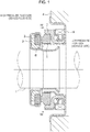
- FIG. 1 is a vertically sectional view showing an example of the mechanical seal, which is an inside mechanical seal in the form of sealing a sealed fluid on the high pressure fluid side to leak from the outer periphery of sliding surfaces toward the inner periphery.
- the mechanical seal is provided with an annular rotating side sealing ring 3 serving as one sliding component provided across a sleeve 2 on the side of a rotating shaft 1 that drives a pump impeller (not shown) on the high pressure fluid side in a state where the rotating side sealing ring 3 is rotatable integrally with this rotating shaft 1, and an annular stationary side sealing ring 5 serving as the other sliding component provided in a housing 4 of a pump in a non-rotating state and an axially movable state.
- FIG. 1 shows a case where width of the sliding surface of the rotating side sealing ring 3 is greater than width of the sliding surface of the stationary side sealing ring 5.
- the present invention is not limited to this but is also applicable to the opposite case as a matter of course.
- Rotation centers of the rotating shaft 1, the rotating side sealing ring 3, and the stationary side sealing ring 5 substantially match with each other.
- the material of the rotating side sealing ring 3 and the stationary side sealing ring 5 is selected from silicon carbide (SiC) excellent in wear resistance, carbon excellent in self-lubricity, etc.
- SiC silicon carbide
- both the sealing rings can be made of SiC or the rotating side sealing ring 3 of SiC and the stationary side sealing ring 5 of carbon can be combined.
- Dimples are arranged on at least any one of the sliding surfaces of the rotating side sealing ring 3 and the stationary side sealing ring 5 that slide with respect to each other.
- the "dimples” are dents formed on the flat sliding surface S, and the shape thereof is not particularly limited.
- the planar shape of the dents includes a circle, a triangle, an ellipse, an oval, or a rectangle.
- the sectional shape of the dents also includes various shapes such as a bowl shape or a square.
- Random arrangement indicates arrangement excluding aligned arrangement in which dimples are arranged on a regular basis, and does not include zigzag arrangement.
- a mechanism to improve the lubricating function and the sealing function is as follows.
- the pressure of the fluid suctioned into the dimples is boosted in the dimples and the fluid is discharged from the dimples. That is, the suction of the fluid into the dimples and the discharge of the fluid whose pressure is boosted from the dimples are consecutively performed.
- the fluid suctioned into and discharged from the dimples arranged on the inner peripheral side of the sliding surface is consecutively and repeatedly suctioned into and discharged from the dimples arranged on the further outer diameter side.
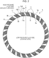
- plural (twenty-four in FIG. 2 ) random dimple groups 11 are arranged on the sliding surface S of the stationary side sealing ring 5 at equal intervals.
- plural dimples 10 are randomly arranged over the entire length from an inner peripheral portion 5a (leakage side) to an outer peripheral portion 5b (sealed fluid side) of the sliding surface S.
- Radial portions 11a, 11b of the random dimple group 11 are partitioned by land portions 15 extending in the radial direction.
- the random dimple groups 11 are formed to have the substantially same width as each other from the inner peripheral portion 5a (leakage side) to the outer peripheral portion 5b (sealed fluid side) of the sliding surface S.
- An inside circumferential portion 11c where the random dimple group is in contact with the leakage side is partitioned by the inner peripheral portion 5a of the sliding surface S.
- An outside circumferential portion 11d where the random dimple group is in contact with the sealed fluid side is partitioned by the outer peripheral portion 5b of the sliding surface S.
- the inside circumferential portion 11c and the outside circumferential portion 11d are formed to have the substantially same width as each other.
- Each of the land portions 15 is a flat surface having narrower circumferential width than circumferential width of the random dimple group 11 over the entire length from the inner peripheral portion 5a (leakage side) to the outer peripheral portion 5b (sealed fluid side) of the sliding surface S.
- the random dimple group 11 is separated from other adjacent random dimple groups 11.
- the land portion 15 and the radial portions 11a, 11b of the random dimple group 11 are inclined with respect to the radial axis r passing through the rotation center.
- the radial portions 11a, 11b of the random dimple group 11 have inclination with respect to the radial axis r. Thereby, in comparison to a case where the radial portions do not have the inclination, it is possible to furthermore enhance a sealing effect.
- FIG. 2 in a case where the rotating side sealing ring 3 is rotated anti-clockwise with respect to the stationary side sealing ring 5, by inclining the random dimple group 11 anti-clockwise, that is, to the receding side in the rotation direction, the fluid from the leakage side to the random dimple group 11 is efficiently taken in, and a sealing performance is improved.
- FIG. 3 is modification of FIG. 2 , and a pair of radial portions 21a, 21b of a random dimple group 21 is inclined to open toward the radially outside.
- circumferential width of an outside circumferential portion 21d of the random dimple group 21 is increased more than circumferential width of an inside circumferential portion 21c, and a flow of the fluid from the sealed fluid side to the random dimple group 21 is increased, so that it is possible to improve a lubricating effect. That is, in the random dimple group 21, by changing inclination of the pair of radial portions 21a, 21b, it is possible to improve a fluid lubricating performance more than the random dimple group 11 of FIG. 2 .
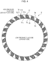
- FIG. 4 is further modification of FIG. 2 , and a pair of radial portions 31a, 31b of a random dimple group 31 is inclined to open toward the radially inside.
- circumferential width of an inside circumferential portion 31c of the random dimple group 31 is increased more than circumferential width of an outside circumferential portion 31d, and a flow of the fluid from the leakage side to the random dimple group 31 is increased, so that it is possible to furthermore improve the sealing effect.
- the random dimple groups 11, 21, 31 formed on the sliding surface S can improve the contradictory functions of lubricating and sealing.
- the random dimple group 11 has the same shape as other adjacent random dimple groups.
- the present invention is not limited to this but the random dimple group 11 may have a different shape from other adjacent random dimple groups.
- the random dimple groups 21, 31 of the examples of FIGS. 3 , 4 it is possible to adapt to various conditions by combining and arranging random dimple groups having different shapes.
- the twenty-four random dimple groups 11 are arranged on the sliding surface S at equal intervals.
- the present invention is not limited to twenty-four and equal intervals but one random dimple group and one land portion may be arranged, or 2, 3, ..., 36 or more random dimple groups and 2, 3, ..., 36 or more land portions may be arranged.
- the plural random dimple groups 11 are formed in a band shape extending in the radial direction, respectively having equal center angles at the radially same positions.
- the plural land portions 15 are formed in flat surfaces extending in the radial direction, respectively having equal center angles at the radially same positions.
- the present invention is not limited to this but at the radially same positions, random dimple groups having different center angles may be combined with land portions having different center angles.
- random dimple groups having equal center angles may be combined with land portions having different center angles.
- plural random dimple groups having different center angles may be combined with land portions having equal center angles. The same applies to the random dimple groups 21, 31 of the examples of FIGS. 3 , 4 .
- FIGS. 5 and 6 Sliding components according to a second embodiment will be described with reference to FIGS. 5 and 6 .
- the sliding components according to the second embodiment are different in a point that at least one set of adjacent random dimple groups has different shapes from each other, and the other basic configurations are the same as the first embodiment.
- the same members will be given the same reference signs and duplicated description will be omitted.
- shapes of adjacent random dimple groups 41, 42 are different from each other.
- a pair of radial portions 41a, 41b of the random dimple group 41 is inclined to open toward the radially outside.
- circumferential width of an outside circumferential portion 41d of the random dimple group 41 is increased more than circumferential width of an inside circumferential portion 41c, and a flow of a fluid from the sealed fluid side to the random dimple group 41 is increased, so that it is possible to further improve the lubricating effect.
- a pair of radial portions 42a, 42b of the random dimple group 42 adjacent to the random dimple group 41 is inclined to open toward the radially inside.
- circumferential width of an inside circumferential portion 42c of the random dimple group 42 is increased more than circumferential width of an outside circumferential portion 42d, and a flow of the fluid from the leakage side to the random dimple group 42 is increased, so that it is possible to further improve the sealing effect.
- the random dimple group 41 with which the fluid lubricating effect is improved and the random dimple group 42 with which the sealing effect is enhanced it is possible to provide the sliding components with which contradictory performances are improved.
- the random dimple groups 41, 42 are formed symmetrically in the left and right direction. Thereby, even when the sliding component is rotated in any directions, it is possible to exert the same sealing effect and the same fluid lubricating effect.
- FIG. 6 is a modified example of FIG. 5 , and is different from FIG. 5 in a point that adjacent random dimple groups 51, 52 are formed asymmetrically in the left and right direction. Thereby, rotation of the sliding component can be efficiently utilized. Thus, it is possible to further enhance the sealing effect and the fluid lubricating performance of the random dimple groups 51, 52 of FIG. 6 in comparison to the random dimple groups 41, 42 of FIG. 5 .
- the sliding components of the second embodiment exert the following specific effects.
- the nine random dimple groups 41, the nine random dimple groups 42, and the eighteen land portions are arranged on the sliding surface S.
- the present invention is not limited to this but one random dimple group 41, one random dimple group 42, and two land portions may be arranged to form a sliding component.
- 2, 3, ..., 36 or more random dimple groups 41, 2, 3, ..., 36 or more random dimple groups 42, and 4, 6, ..., 72 or more land portions may be arranged.
- the same also applies to the random dimple groups 21, 31 of the examples of FIGS. 3 , 4 .
- the plural random dimple groups 41, 42 formed on the sliding surface S are formed in a band shape respectively having equal center angles at the radially same positions.
- the plural land portions 15 are formed in flat surfaces respectively having equal center angles at the radially same positions.
- the present invention is not limited to this but at the radially same positions, different random dimple groups may be combined with land portions having different center angles.
- random dimple groups having equal center angles may be combined with land portions having different center angles.
- random dimple groups having different center angles may be combined with land portions having equal center angles. The same applies to the example of FIG. 6 .
- the sliding component can also be utilized as a sliding component of a bearing to slide with a rotating shaft while sealing lubricating oil on the axially one side of a cylindrical sliding surface.
- the outer peripheral side of the sliding component is described as the high pressure fluid side (sealed fluid side), and the inner peripheral side as the low pressure fluid side (leakage side).
- the present invention is not limited to this but can be applied to a case where the outer peripheral side of the sliding component is the low pressure fluid side (leakage side) and the inner peripheral side is the high pressure fluid side (sealed fluid side).
Landscapes
- Engineering & Computer Science (AREA)
- General Engineering & Computer Science (AREA)
- Mechanical Engineering (AREA)
- Chemical & Material Sciences (AREA)
- Oil, Petroleum & Natural Gas (AREA)
- Physics & Mathematics (AREA)
- Fluid Mechanics (AREA)
- Mechanical Sealing (AREA)
- Sliding-Contact Bearings (AREA)
Abstract
Description
- The present invention relates to a sliding component suitable, for example, as a mechanical seal, a sliding bearing, and other sliding units. In particular, the present invention relates to a sliding component such as a sealing ring or a bearing that requires reduction of friction by interposing a fluid between sliding surfaces, and prevention of leakage of the fluid from the sliding surfaces.
- In a mechanical seal serving as an example of a sliding component, while maintaining a sealing property, sliding friction during rotation is required to be reduced to the extreme. By variously texturing the sliding surfaces, a method of reducing friction is realized. For example, as one of texturing, arrangement of dimples on the sliding surfaces is known.
- Conventionally, in a case where dimples are provided on a sliding surface, plural dimples are arranged and aligned in order in general. For example, in the invention described in
JP 2003-343741 A - Conventionally, in order to improve a lubricating property, random arrangement of plural dimples is also known. For example, in the invention described in
JP 2001-221179 A Patent Document 2"), plural dimples are randomly arranged on an inner wall of a cylinder of a rotary compressor and a leading end surface and both side end surfaces of a sliding vane. -
- Patent Document 1:
JP 2003-343741 A - Patent Document 2:
JP 2001-221179 A - However, in the invention described in Patent Document 1, since the dimples are arranged and aligned in order, an effect of suctioning from the leakage side to the sliding surface and an effect of flowing from the sealed fluid side to the sliding surface are low. Thus, there is a need for a complicated configuration in which the leading ends in the rotation direction of the dimples on the outer peripheral side are inclined toward the outer peripheral side and the leading ends in the rotation direction of the dimples on the inner peripheral side are inclined toward the inner peripheral side. Since a fluid concentrates on a radially center portion of the sliding surface, there is also a problem that the entire sliding surface cannot be uniformly lubricated.
- The invention described in
Patent Document 2 is just to randomly arrange the plural dimples in order to improve the lubricating property, and a performance of random dimples is not sufficiently obtained. - An object of the present invention is to provide sliding components with which a performance of a random dimple group in which plural dimples are randomly arranged is sufficiently obtained and a lubricating performance and a sealing performance are improved.
- To attain the above object, sliding components according to a first aspect of the present invention are a pair of sliding components having sliding surfaces that slide with respect to each other, characterized in that at least the sliding surface on one side includes a random dimple group in which plural dimples are randomly arranged, and at least one land portion that partitions radial portions of the random dimple group.
- According to the first aspect, circumferential movement of a fluid flowing into the sliding surface is blocked by the land portion and positive pressure is generated. Thus, a fluid lubricating effect and a sealing effect of the random dimple group are synergistically increased, and it is possible to provide the sliding components excellent in a sealing property and a lubricating property. The fluid lubricating effect is an effect of letting the fluid flowing from the sealed fluid side to the sliding surface and improving the lubricating property. The sealing effect is also called as a pumping effect of suctioning the fluid from the leakage side to the sliding surface and improving the sealing property.
- The sliding components according to a second aspect of the present invention are characterized in that the radial portions of the random dimple group are inclined with respect to the radial axis.
- According to the second aspect, by inclining the radial portions of the random dimple group with respect to the radial axis, it is possible to change influence degrees of the fluid lubricating effect and the sealing effect.
- The sliding components according to a third aspect of the present invention are characterized in that the pair of radial portions of the random dimple group is inclined to open toward the radially inside.
- According the third aspect, the inner diameter side of the random dimple group is formed to be large. Thus, it is possible to take more fluid from the leakage side into the sliding surface and enhance the sealing effect.
- The sliding components according to a fourth aspect of the present invention are characterized in that the pair of radial portions of the random dimple group is inclined to open toward the radially outside.
- According to the fourth aspect, the outer diameter side of the random dimple group is formed to be large. Thus, it is possible to take more fluid from the sealed fluid side into the sliding surface and enhance the fluid lubricating effect.
- The sliding components according to a fifth aspect of the present invention are characterized in that the shape of the random dimple group is different from the shape of other random dimple groups adjacent to the random dimple group.
- According to the fifth aspect, by combining and arranging the random dimple groups having different sealing effects and fluid lubricating effects, it is possible to adapt to various sliding speeds and temperatures (fluid viscosity).
- The sliding components according to a sixth aspect of the present invention are characterized in that the pair of radial portions of the random dimple group is inclined to open toward the radially outside, and a pair of radial portions of the random dimple group adjacent to the random dimple group is inclined to open toward the radially inside.
- According to the sixth aspect, by combining and arranging the random dimples excellent in a sealing performance and the random dimples excellent in a lubricating performance, it is possible to adapt to various sliding speeds and temperatures (fluid viscosity).
-
-
FIG. 1 is a vertically sectional view showing an example of a mechanical seal according to a first embodiment of the present invention. -
FIG. 2 is a W-W arrow view ofFIG. 1 , showing an example of a sliding surface of a sliding component according to the first embodiment of the present invention. -
FIG. 3 is a W-W arrow view ofFIG. 1 , showing a modified example of the sliding surface of the sliding component according to the first embodiment of the present invention. -
FIG. 4 is a W-W arrow view ofFIG. 1 , showing another modified example of the sliding surface of the sliding component according to the first embodiment of the present invention. -
FIG. 5 is a W-W arrow view ofFIG. 1 , showing a sliding surface of a sliding component according to a second embodiment of the present invention. -
FIG. 6 is a W-W arrow view ofFIG. 1 , showing a modified example of the sliding surface of the sliding component according to the second embodiment of the present invention. - Hereinafter, with reference to the drawings, modes for carrying out the present invention will be described as examples based on embodiments. However, the dimensions, the materials, the shapes, the relative arrangements, etc. of constituent components described in the embodiments are not intended to limit the scope of the present invention only to them unless otherwise described explicitly.
- With reference to
FIGS. 1 to 4 , sliding components according to a first embodiment of the present invention will be described. - In the following embodiment, as an example, a mechanical seal that is an example of the sliding components will be described. However, the present invention is not limited to this but for example can also be utilized as a sliding component of a bearing that slide with a rotating shaft while sealing lubricating oil on the axially one side of a cylindrical sliding surface.
- The outer peripheral side of the sliding component forming the mechanical seal will be described as the high pressure fluid side (sealed fluid side), and the inner peripheral side as the low pressure fluid side (leakage side).
-
FIG. 1 is a vertically sectional view showing an example of the mechanical seal, which is an inside mechanical seal in the form of sealing a sealed fluid on the high pressure fluid side to leak from the outer periphery of sliding surfaces toward the inner periphery. The mechanical seal is provided with an annular rotatingside sealing ring 3 serving as one sliding component provided across asleeve 2 on the side of a rotating shaft 1 that drives a pump impeller (not shown) on the high pressure fluid side in a state where the rotatingside sealing ring 3 is rotatable integrally with this rotating shaft 1, and an annular stationaryside sealing ring 5 serving as the other sliding component provided in a housing 4 of a pump in a non-rotating state and an axially movable state. With a coiledwave spring 6 and abellows 7 axially biasing the stationaryside sealing ring 5, the sealing rings slide in close contact with each other at sliding surfaces S. That is, this mechanical seal prevents an outflow of the sealed fluid from the outer peripheral side of the rotating shaft 1 to the inner peripheral side at the sliding surfaces S of the rotatingside sealing ring 3 and the stationaryside sealing ring 5. -
FIG. 1 shows a case where width of the sliding surface of the rotatingside sealing ring 3 is greater than width of the sliding surface of the stationaryside sealing ring 5. However, the present invention is not limited to this but is also applicable to the opposite case as a matter of course. Rotation centers of the rotating shaft 1, the rotating side sealingring 3, and the stationary side sealingring 5 substantially match with each other. - The material of the rotating
side sealing ring 3 and the stationaryside sealing ring 5 is selected from silicon carbide (SiC) excellent in wear resistance, carbon excellent in self-lubricity, etc. For example, both the sealing rings can be made of SiC or the rotatingside sealing ring 3 of SiC and the stationaryside sealing ring 5 of carbon can be combined. - Dimples are arranged on at least any one of the sliding surfaces of the rotating side sealing
ring 3 and the stationary side sealingring 5 that slide with respect to each other. - In the present invention, the "dimples" are dents formed on the flat sliding surface S, and the shape thereof is not particularly limited. For example, the planar shape of the dents includes a circle, a triangle, an ellipse, an oval, or a rectangle. The sectional shape of the dents also includes various shapes such as a bowl shape or a square.
- In the present example, a case where plural dimples are randomly arranged on the sliding surface S of the stationary
side sealing ring 5 will be described. In this case, dimples may be provided or not provided in the rotatingside sealing ring 3. Random arrangement indicates arrangement excluding aligned arrangement in which dimples are arranged on a regular basis, and does not include zigzag arrangement. - By randomly arranging dimple groups on the sliding surface, it is possible to improve contradictory functions of lubricating and sealing. A mechanism to improve the lubricating function and the sealing function is as follows.
- When the opposing sliding surface is relatively moved, the fluid is suctioned into hole portions of the dimples formed on the sliding surface by viscosity of the fluid, and negative pressure is generated in a part on the upstream side of the hole portions, and positive pressure is generated in a part on the downstream side by the wedge effect. At that time, in the negative pressure part on the upstream side of the hole portions, a liquid film is broken and a cavity is formed due to steam and bubbles of a liquid (cavitation), so that negative pressure is cancelled. As a result, only positive pressure remains and a load capacity is generated, and hence the sliding surface S is brought up. When the sliding surface S is brought up, a gap between the two sliding surfaces that slide with respect to each other is increased, and the fluid having a lubricating property flows into the sliding surfaces S, so that the lubricating function is obtained.
- The pressure of the fluid suctioned into the dimples is boosted in the dimples and the fluid is discharged from the dimples. That is, the suction of the fluid into the dimples and the discharge of the fluid whose pressure is boosted from the dimples are consecutively performed. When the plural dimples are randomly arranged, the fluid suctioned into and discharged from the dimples arranged on the inner peripheral side of the sliding surface is consecutively and repeatedly suctioned into and discharged from the dimples arranged on the further outer diameter side. Thus, the sealing function in which the fluid is gradually delivered from the inner diameter side to the outer dimeter side is obtained.
- In
FIG. 2 , plural (twenty-four inFIG. 2 )random dimple groups 11 are arranged on the sliding surface S of the stationaryside sealing ring 5 at equal intervals. In each of therandom dimple groups 11,plural dimples 10 are randomly arranged over the entire length from an innerperipheral portion 5a (leakage side) to an outerperipheral portion 5b (sealed fluid side) of the sliding surfaceS. Radial portions random dimple group 11 are partitioned byland portions 15 extending in the radial direction. Therandom dimple groups 11 are formed to have the substantially same width as each other from the innerperipheral portion 5a (leakage side) to the outerperipheral portion 5b (sealed fluid side) of the sliding surface S. An insidecircumferential portion 11c where the random dimple group is in contact with the leakage side is partitioned by the innerperipheral portion 5a of the sliding surface S. An outsidecircumferential portion 11d where the random dimple group is in contact with the sealed fluid side is partitioned by the outerperipheral portion 5b of the sliding surface S. The insidecircumferential portion 11c and theoutside circumferential portion 11d are formed to have the substantially same width as each other. - Each of the
land portions 15 is a flat surface having narrower circumferential width than circumferential width of therandom dimple group 11 over the entire length from the innerperipheral portion 5a (leakage side) to the outerperipheral portion 5b (sealed fluid side) of the sliding surface S. By theland portion 15, therandom dimple group 11 is separated from other adjacentrandom dimple groups 11. Theland portion 15 and theradial portions random dimple group 11 are inclined with respect to the radial axis r passing through the rotation center. - By separating the adjacent
random dimple groups 11 by theland portion 15, circumferential movement of the fluid flowing into the sliding surface S is blocked, and a dynamic pressure generation effect of generating positive pressure is obtained. The gap between the two sliding surfaces that slide with respect to each other is increased and the fluid having the lubricating property flows into the sliding surfaces S, so that a fluid lubricating operation is obtained. - Further, the
radial portions random dimple group 11 have inclination with respect to the radial axis r. Thereby, in comparison to a case where the radial portions do not have the inclination, it is possible to furthermore enhance a sealing effect. For example, inFIG. 2 , in a case where the rotatingside sealing ring 3 is rotated anti-clockwise with respect to the stationaryside sealing ring 5, by inclining therandom dimple group 11 anti-clockwise, that is, to the receding side in the rotation direction, the fluid from the leakage side to therandom dimple group 11 is efficiently taken in, and a sealing performance is improved. -
FIG. 3 is modification ofFIG. 2 , and a pair ofradial portions random dimple group 21 is inclined to open toward the radially outside. Thereby, circumferential width of anoutside circumferential portion 21d of therandom dimple group 21 is increased more than circumferential width of an insidecircumferential portion 21c, and a flow of the fluid from the sealed fluid side to therandom dimple group 21 is increased, so that it is possible to improve a lubricating effect. That is, in therandom dimple group 21, by changing inclination of the pair ofradial portions random dimple group 11 ofFIG. 2 . -
FIG. 4 is further modification ofFIG. 2 , and a pair ofradial portions random dimple group 31 is inclined to open toward the radially inside. Thereby, circumferential width of an insidecircumferential portion 31c of therandom dimple group 31 is increased more than circumferential width of anoutside circumferential portion 31d, and a flow of the fluid from the leakage side to therandom dimple group 31 is increased, so that it is possible to furthermore improve the sealing effect. - The following specific effects are exerted in the sliding components of the first embodiment.
- The
random dimple groups - By separating and partitioning the
random dimple groups 11 by theland portions 15, the circumferential movement of the fluid flowing into the sliding surface S is blocked and by the dynamic pressure generation effect of generating positive pressure, it is possible to furthermore improve a fluid lubricating effect. The same effect is exerted in therandom dimple groups - By changing inclination magnitude or a mode of inclination of the
radial portions random dimple group 11, it is possible to enhance the sealing effect or to enhance the fluid lubricating effect. Thereby, by adjusting the inclination magnitude or the mode of inclination of theradial portions random dimple group 11 according to sliding speed or a temperature (fluid viscosity), it is possible to provide the sliding components that adapt to various conditions. The same effect is exerted in therandom dimple groups - In the example of
FIG. 2 , therandom dimple group 11 has the same shape as other adjacent random dimple groups. However, the present invention is not limited to this but therandom dimple group 11 may have a different shape from other adjacent random dimple groups. For example, by combining and arranging random dimple groups having different shapes from the shape of therandom dimple group 11 according to sliding speed or a temperature (fluid viscosity), it is possible to adapt to various conditions. Regarding therandom dimple groups FIGS. 3 ,4 , it is possible to adapt to various conditions by combining and arranging random dimple groups having different shapes. - In the example of
FIG. 2 , the twenty-fourrandom dimple groups 11 are arranged on the sliding surface S at equal intervals. However, the present invention is not limited to twenty-four and equal intervals but one random dimple group and one land portion may be arranged, or 2, 3, ..., 36 or more random dimple groups and 2, 3, ..., 36 or more land portions may be arranged. The same applies to therandom dimple groups FIGS. 3 ,4 . - In the example of
FIG. 2 , the pluralrandom dimple groups 11 are formed in a band shape extending in the radial direction, respectively having equal center angles at the radially same positions. Theplural land portions 15 are formed in flat surfaces extending in the radial direction, respectively having equal center angles at the radially same positions. However, the present invention is not limited to this but at the radially same positions, random dimple groups having different center angles may be combined with land portions having different center angles. Alternatively, at the radially same positions, random dimple groups having equal center angles may be combined with land portions having different center angles. Further, at the radially same positions, plural random dimple groups having different center angles may be combined with land portions having equal center angles. The same applies to therandom dimple groups FIGS. 3 ,4 . - Sliding components according to a second embodiment will be described with reference to
FIGS. 5 and6 . The sliding components according to the second embodiment are different in a point that at least one set of adjacent random dimple groups has different shapes from each other, and the other basic configurations are the same as the first embodiment. The same members will be given the same reference signs and duplicated description will be omitted. - As shown in
FIG. 5 , shapes of adjacentrandom dimple groups radial portions random dimple group 41 is inclined to open toward the radially outside. Thereby, circumferential width of anoutside circumferential portion 41d of therandom dimple group 41 is increased more than circumferential width of an insidecircumferential portion 41c, and a flow of a fluid from the sealed fluid side to therandom dimple group 41 is increased, so that it is possible to further improve the lubricating effect. Meanwhile, a pair ofradial portions random dimple group 42 adjacent to therandom dimple group 41 is inclined to open toward the radially inside. Thereby, circumferential width of an insidecircumferential portion 42c of therandom dimple group 42 is increased more than circumferential width of anoutside circumferential portion 42d, and a flow of the fluid from the leakage side to therandom dimple group 42 is increased, so that it is possible to further improve the sealing effect. In such a way, by alternately arranging therandom dimple group 41 with which the fluid lubricating effect is improved and therandom dimple group 42 with which the sealing effect is enhanced, it is possible to provide the sliding components with which contradictory performances are improved. - Further, the
random dimple groups -
FIG. 6 is a modified example ofFIG. 5 , and is different fromFIG. 5 in a point that adjacentrandom dimple groups random dimple groups FIG. 6 in comparison to therandom dimple groups FIG. 5 . For example, in a case where the rotatingside sealing ring 3 is rotated anti-clockwise with respect to the stationaryside sealing ring 5, by inclining aradial portion 51b of therandom dimple group 51 anti-clockwise, that is, further to the receding side in the rotation direction, a flow of the fluid from the sealed fluid side to therandom dimple group 51 is increased, so that it is possible to enhance the fluid lubricating effect. By also inclining aradial portion 52a of therandom dimple group 52 further to the receding side in the rotation direction, a flow of the fluid from the leakage side to therandom dimple group 52 is increased, so that it is possible to enhance the fluid lubricating effect. - The sliding components of the second embodiment exert the following specific effects.
- By alternately arranging the
random dimple groups random dimple groups - By respectively independently changing inclination magnitude or a mode of inclination of the
radial portions random dimple groups random dimple groups random dimple groups 51 and therandom dimple groups 52 having different characteristics from each other, it is possible to provide the sliding components that adapt to various sliding speeds or temperatures (fluid viscosity). - In the example of
FIG. 5 , the ninerandom dimple groups 41, the ninerandom dimple groups 42, and the eighteen land portions are arranged on the sliding surface S. However, the present invention is not limited to this but onerandom dimple group 41, onerandom dimple group 42, and two land portions may be arranged to form a sliding component. Further, 2, 3, ..., 36 or morerandom dimple groups random dimple groups random dimple groups FIGS. 3 ,4 . - In the example of
FIG. 5 , the pluralrandom dimple groups plural land portions 15 are formed in flat surfaces respectively having equal center angles at the radially same positions. However, the present invention is not limited to this but at the radially same positions, different random dimple groups may be combined with land portions having different center angles. Alternatively, at the radially same positions, random dimple groups having equal center angles may be combined with land portions having different center angles. Further, random dimple groups having different center angles may be combined with land portions having equal center angles. The same applies to the example ofFIG. 6 . - In the first and second embodiments, the examples in which the sliding component is used for at least any one of the pair of the rotating sealing ring and the stationary sealing ring in the mechanical seal device is described. However, the sliding component can also be utilized as a sliding component of a bearing to slide with a rotating shaft while sealing lubricating oil on the axially one side of a cylindrical sliding surface.
- In the first and second embodiments, the outer peripheral side of the sliding component is described as the high pressure fluid side (sealed fluid side), and the inner peripheral side as the low pressure fluid side (leakage side). However, the present invention is not limited to this but can be applied to a case where the outer peripheral side of the sliding component is the low pressure fluid side (leakage side) and the inner peripheral side is the high pressure fluid side (sealed fluid side).
-
- 1
- rotating shaft
- 2
- sleeve
- 3
- rotating side sealing ring
- 4
- housing
- 5
- stationary side sealing ring
- 5a
- inner peripheral portion
- 5b
- outer peripheral portion
- 6
- coiled wave spring
- 7
- bellows
- 10
- dimple
- 11
- random dimple group
- 11a
- radial portion
- 11b
- radial portion
- 15
- land portion
- 21
- random dimple group
- 21a
- radial portion
- 21b
- radial portion
- 25
- land portion
- 31
- random dimple group
- 31a
- radial portion
- 31b
- radial portion
- 35
- land portion
- 41
- random dimple group
- 41a
- radial portion
- 41b
- radial portion
- 45
- land portion
- 51
- random dimple group
- 51a
- radial portion
- 51b
- radial portion
- 55
- land portion
- 52
- random dimple group
- 52a
- radial portion
- 52b
- radial portion
- 56
- land portion
- S
- sliding surface
- r
- radial axis
Claims (6)
- A pair of sliding components having sliding surfaces that slide with respect to each other, characterized in that at least the sliding surface on one side includes a random dimple group in which plural dimples are randomly arranged, and at least one land portion that partitions radial portions of the random dimple group.
- The sliding components according to claim 1, characterized in that the radial portions of the random dimple group are inclined with respect to the radial axis.
- The sliding components according to claim 1 or 2, characterized in that the shape of the random dimple group is different from the shape of other random dimple groups adjacent to the random dimple group.
- The sliding components according to any one of claims 1 to 3, characterized in that the pair of radial portions of the random dimple group is inclined to open toward the radially inside.
- The sliding components according to any one of claims 1 to 3, characterized in that the pair of radial portions of the random dimple group is inclined to open toward the radially outside.
- The sliding components according to any one of claims 1 to 3, characterized in that the pair of radial portions of the random dimple group is inclined to open toward the radially outside, and a pair of radial portions of the random dimple group adjacent to the random dimple group is inclined to open toward the radially inside.
Applications Claiming Priority (2)
| Application Number | Priority Date | Filing Date | Title |
|---|---|---|---|
| JP2017099486 | 2017-05-19 | ||
| PCT/JP2018/018438 WO2018212108A1 (en) | 2017-05-19 | 2018-05-12 | Sliding component |
Publications (3)
| Publication Number | Publication Date |
|---|---|
| EP3627012A1 true EP3627012A1 (en) | 2020-03-25 |
| EP3627012A4 EP3627012A4 (en) | 2021-01-27 |
| EP3627012B1 EP3627012B1 (en) | 2022-01-19 |
Family
ID=64273893
Family Applications (1)
| Application Number | Title | Priority Date | Filing Date |
|---|---|---|---|
| EP18803130.6A Active EP3627012B1 (en) | 2017-05-19 | 2018-05-12 | Sliding component |
Country Status (6)
| Country | Link |
|---|---|
| US (1) | US11168793B2 (en) |
| EP (1) | EP3627012B1 (en) |
| JP (1) | JP7171553B2 (en) |
| KR (1) | KR102346371B1 (en) |
| CN (1) | CN110573774B (en) |
| WO (1) | WO2018212108A1 (en) |
Families Citing this family (5)
| Publication number | Priority date | Publication date | Assignee | Title |
|---|---|---|---|---|
| JP7275028B2 (en) * | 2017-05-19 | 2023-05-17 | イーグル工業株式会社 | sliding parts |
| EP3693638A4 (en) * | 2017-10-03 | 2021-06-23 | Eagle Industry Co., Ltd. | Sliding component |
| JP7381721B2 (en) * | 2020-04-07 | 2023-11-15 | イーグル工業株式会社 | sliding parts |
| KR102744486B1 (en) * | 2020-04-07 | 2024-12-18 | 이글 고오교 가부시키가이샤 | Sliding parts |
| US20250223972A1 (en) * | 2024-01-05 | 2025-07-10 | John Crane Inc. | Drive ring for rotary shaft equipment seals |
Family Cites Families (16)
| Publication number | Priority date | Publication date | Assignee | Title |
|---|---|---|---|---|
| JPS57161366A (en) * | 1981-03-31 | 1982-10-04 | Eagle Ind Co Ltd | Mechanical seal |
| JPS61168566A (en) | 1985-01-17 | 1986-07-30 | イ−グル工業株式会社 | Sliding material for mechanical seal |
| JPS61190975A (en) * | 1986-02-21 | 1986-08-25 | Sony Corp | Manufacture of insulated gate type field-effect transistor |
| CH677266A5 (en) * | 1986-10-28 | 1991-04-30 | Pacific Wietz Gmbh & Co Kg | |
| JPH0314371U (en) * | 1989-06-26 | 1991-02-13 | ||
| JP2001221179A (en) | 2000-02-09 | 2001-08-17 | Matsushita Electric Ind Co Ltd | Rotary compressor |
| JP4495402B2 (en) | 2002-03-19 | 2010-07-07 | イーグル工業株式会社 | Sliding parts |
| US6902168B2 (en) * | 2002-03-19 | 2005-06-07 | Eagle Industry Co., Ltd. | Sliding element |
| JP4205910B2 (en) * | 2002-04-02 | 2009-01-07 | イーグル工業株式会社 | Sliding parts |
| JP4316956B2 (en) * | 2002-10-23 | 2009-08-19 | イーグル工業株式会社 | Sliding parts |
| JP4719414B2 (en) * | 2003-12-22 | 2011-07-06 | イーグル工業株式会社 | Sliding parts |
| JP5871289B2 (en) * | 2011-09-03 | 2016-03-01 | イーグル工業株式会社 | Sliding parts |
| CN104185755B (en) * | 2012-05-21 | 2016-08-17 | 伊格尔工业股份有限公司 | Slide unit |
| CN104919229B (en) | 2013-04-24 | 2017-05-31 | 伊格尔工业股份有限公司 | sliding parts |
| US9829043B2 (en) * | 2013-09-18 | 2017-11-28 | Eagle Industry Co., Ltd. | Sliding parts |
| DE112014005773A5 (en) * | 2013-12-20 | 2016-09-29 | Magna Powertrain Bad Homburg GmbH | Compressor for a power-heat engine |
-
2018
- 2018-05-12 US US16/607,322 patent/US11168793B2/en active Active
- 2018-05-12 KR KR1020197031288A patent/KR102346371B1/en active Active
- 2018-05-12 WO PCT/JP2018/018438 patent/WO2018212108A1/en not_active Ceased
- 2018-05-12 JP JP2019518756A patent/JP7171553B2/en active Active
- 2018-05-12 EP EP18803130.6A patent/EP3627012B1/en active Active
- 2018-05-12 CN CN201880028070.4A patent/CN110573774B/en active Active
Also Published As
| Publication number | Publication date |
|---|---|
| US20200378501A1 (en) | 2020-12-03 |
| CN110573774B (en) | 2022-06-17 |
| EP3627012B1 (en) | 2022-01-19 |
| KR20190131090A (en) | 2019-11-25 |
| CN110573774A (en) | 2019-12-13 |
| KR102346371B1 (en) | 2022-01-03 |
| US11168793B2 (en) | 2021-11-09 |
| JP7171553B2 (en) | 2022-11-15 |
| JPWO2018212108A1 (en) | 2020-05-21 |
| EP3627012A4 (en) | 2021-01-27 |
| WO2018212108A1 (en) | 2018-11-22 |
Similar Documents
| Publication | Publication Date | Title |
|---|---|---|
| US11708911B2 (en) | Sliding component | |
| EP3309431B1 (en) | Slide component | |
| EP3627012B1 (en) | Sliding component | |
| EP3540274B1 (en) | Sliding component | |
| EP3299685B1 (en) | Sliding component | |
| EP2977654B1 (en) | Sliding component | |
| CN114127430B (en) | Sliding parts | |
| EP3091257B1 (en) | Sliding component | |
| EP3627011B1 (en) | Sliding component | |
| EP3653914A1 (en) | Sliding parts | |
| US10808752B2 (en) | Sliding members | |
| US11248707B2 (en) | Sliding component | |
| CN112424514A (en) | Sliding component | |
| EP3862600B1 (en) | Sliding member | |
| US11994217B2 (en) | Sliding component | |
| US12038087B2 (en) | Sliding component |
Legal Events
| Date | Code | Title | Description |
|---|---|---|---|
| STAA | Information on the status of an ep patent application or granted ep patent |
Free format text: STATUS: THE INTERNATIONAL PUBLICATION HAS BEEN MADE |
|
| PUAI | Public reference made under article 153(3) epc to a published international application that has entered the european phase |
Free format text: ORIGINAL CODE: 0009012 |
|
| STAA | Information on the status of an ep patent application or granted ep patent |
Free format text: STATUS: REQUEST FOR EXAMINATION WAS MADE |
|
| 17P | Request for examination filed |
Effective date: 20191104 |
|
| AK | Designated contracting states |
Kind code of ref document: A1 Designated state(s): AL AT BE BG CH CY CZ DE DK EE ES FI FR GB GR HR HU IE IS IT LI LT LU LV MC MK MT NL NO PL PT RO RS SE SI SK SM TR |
|
| AX | Request for extension of the european patent |
Extension state: BA ME |
|
| DAV | Request for validation of the european patent (deleted) | ||
| DAX | Request for extension of the european patent (deleted) | ||
| A4 | Supplementary search report drawn up and despatched |
Effective date: 20210114 |
|
| RIC1 | Information provided on ipc code assigned before grant |
Ipc: F16J 15/34 20060101AFI20201223BHEP |
|
| GRAP | Despatch of communication of intention to grant a patent |
Free format text: ORIGINAL CODE: EPIDOSNIGR1 |
|
| STAA | Information on the status of an ep patent application or granted ep patent |
Free format text: STATUS: GRANT OF PATENT IS INTENDED |
|
| INTG | Intention to grant announced |
Effective date: 20210922 |
|
| GRAS | Grant fee paid |
Free format text: ORIGINAL CODE: EPIDOSNIGR3 |
|
| GRAA | (expected) grant |
Free format text: ORIGINAL CODE: 0009210 |
|
| STAA | Information on the status of an ep patent application or granted ep patent |
Free format text: STATUS: THE PATENT HAS BEEN GRANTED |
|
| AK | Designated contracting states |
Kind code of ref document: B1 Designated state(s): AL AT BE BG CH CY CZ DE DK EE ES FI FR GB GR HR HU IE IS IT LI LT LU LV MC MK MT NL NO PL PT RO RS SE SI SK SM TR |
|
| REG | Reference to a national code |
Ref country code: GB Ref legal event code: FG4D |
|
| REG | Reference to a national code |
Ref country code: CH Ref legal event code: EP |
|
| REG | Reference to a national code |
Ref country code: DE Ref legal event code: R096 Ref document number: 602018029845 Country of ref document: DE |
|
| REG | Reference to a national code |
Ref country code: AT Ref legal event code: REF Ref document number: 1463975 Country of ref document: AT Kind code of ref document: T Effective date: 20220215 |
|
| REG | Reference to a national code |
Ref country code: IE Ref legal event code: FG4D |
|
| REG | Reference to a national code |
Ref country code: LT Ref legal event code: MG9D |
|
| REG | Reference to a national code |
Ref country code: NL Ref legal event code: MP Effective date: 20220119 |
|
| REG | Reference to a national code |
Ref country code: AT Ref legal event code: MK05 Ref document number: 1463975 Country of ref document: AT Kind code of ref document: T Effective date: 20220119 |
|
| PG25 | Lapsed in a contracting state [announced via postgrant information from national office to epo] |
Ref country code: NL Free format text: LAPSE BECAUSE OF FAILURE TO SUBMIT A TRANSLATION OF THE DESCRIPTION OR TO PAY THE FEE WITHIN THE PRESCRIBED TIME-LIMIT Effective date: 20220119 |
|
| PG25 | Lapsed in a contracting state [announced via postgrant information from national office to epo] |
Ref country code: SE Free format text: LAPSE BECAUSE OF FAILURE TO SUBMIT A TRANSLATION OF THE DESCRIPTION OR TO PAY THE FEE WITHIN THE PRESCRIBED TIME-LIMIT Effective date: 20220119 Ref country code: RS Free format text: LAPSE BECAUSE OF FAILURE TO SUBMIT A TRANSLATION OF THE DESCRIPTION OR TO PAY THE FEE WITHIN THE PRESCRIBED TIME-LIMIT Effective date: 20220119 Ref country code: PT Free format text: LAPSE BECAUSE OF FAILURE TO SUBMIT A TRANSLATION OF THE DESCRIPTION OR TO PAY THE FEE WITHIN THE PRESCRIBED TIME-LIMIT Effective date: 20220519 Ref country code: NO Free format text: LAPSE BECAUSE OF FAILURE TO SUBMIT A TRANSLATION OF THE DESCRIPTION OR TO PAY THE FEE WITHIN THE PRESCRIBED TIME-LIMIT Effective date: 20220419 Ref country code: LT Free format text: LAPSE BECAUSE OF FAILURE TO SUBMIT A TRANSLATION OF THE DESCRIPTION OR TO PAY THE FEE WITHIN THE PRESCRIBED TIME-LIMIT Effective date: 20220119 Ref country code: HR Free format text: LAPSE BECAUSE OF FAILURE TO SUBMIT A TRANSLATION OF THE DESCRIPTION OR TO PAY THE FEE WITHIN THE PRESCRIBED TIME-LIMIT Effective date: 20220119 Ref country code: ES Free format text: LAPSE BECAUSE OF FAILURE TO SUBMIT A TRANSLATION OF THE DESCRIPTION OR TO PAY THE FEE WITHIN THE PRESCRIBED TIME-LIMIT Effective date: 20220119 Ref country code: BG Free format text: LAPSE BECAUSE OF FAILURE TO SUBMIT A TRANSLATION OF THE DESCRIPTION OR TO PAY THE FEE WITHIN THE PRESCRIBED TIME-LIMIT Effective date: 20220419 |
|
| PG25 | Lapsed in a contracting state [announced via postgrant information from national office to epo] |
Ref country code: PL Free format text: LAPSE BECAUSE OF FAILURE TO SUBMIT A TRANSLATION OF THE DESCRIPTION OR TO PAY THE FEE WITHIN THE PRESCRIBED TIME-LIMIT Effective date: 20220119 Ref country code: LV Free format text: LAPSE BECAUSE OF FAILURE TO SUBMIT A TRANSLATION OF THE DESCRIPTION OR TO PAY THE FEE WITHIN THE PRESCRIBED TIME-LIMIT Effective date: 20220119 Ref country code: GR Free format text: LAPSE BECAUSE OF FAILURE TO SUBMIT A TRANSLATION OF THE DESCRIPTION OR TO PAY THE FEE WITHIN THE PRESCRIBED TIME-LIMIT Effective date: 20220420 Ref country code: FI Free format text: LAPSE BECAUSE OF FAILURE TO SUBMIT A TRANSLATION OF THE DESCRIPTION OR TO PAY THE FEE WITHIN THE PRESCRIBED TIME-LIMIT Effective date: 20220119 Ref country code: AT Free format text: LAPSE BECAUSE OF FAILURE TO SUBMIT A TRANSLATION OF THE DESCRIPTION OR TO PAY THE FEE WITHIN THE PRESCRIBED TIME-LIMIT Effective date: 20220119 |
|
| PG25 | Lapsed in a contracting state [announced via postgrant information from national office to epo] |
Ref country code: IS Free format text: LAPSE BECAUSE OF FAILURE TO SUBMIT A TRANSLATION OF THE DESCRIPTION OR TO PAY THE FEE WITHIN THE PRESCRIBED TIME-LIMIT Effective date: 20220519 |
|
| REG | Reference to a national code |
Ref country code: DE Ref legal event code: R097 Ref document number: 602018029845 Country of ref document: DE |
|
| PG25 | Lapsed in a contracting state [announced via postgrant information from national office to epo] |
Ref country code: SM Free format text: LAPSE BECAUSE OF FAILURE TO SUBMIT A TRANSLATION OF THE DESCRIPTION OR TO PAY THE FEE WITHIN THE PRESCRIBED TIME-LIMIT Effective date: 20220119 Ref country code: SK Free format text: LAPSE BECAUSE OF FAILURE TO SUBMIT A TRANSLATION OF THE DESCRIPTION OR TO PAY THE FEE WITHIN THE PRESCRIBED TIME-LIMIT Effective date: 20220119 Ref country code: RO Free format text: LAPSE BECAUSE OF FAILURE TO SUBMIT A TRANSLATION OF THE DESCRIPTION OR TO PAY THE FEE WITHIN THE PRESCRIBED TIME-LIMIT Effective date: 20220119 Ref country code: EE Free format text: LAPSE BECAUSE OF FAILURE TO SUBMIT A TRANSLATION OF THE DESCRIPTION OR TO PAY THE FEE WITHIN THE PRESCRIBED TIME-LIMIT Effective date: 20220119 Ref country code: DK Free format text: LAPSE BECAUSE OF FAILURE TO SUBMIT A TRANSLATION OF THE DESCRIPTION OR TO PAY THE FEE WITHIN THE PRESCRIBED TIME-LIMIT Effective date: 20220119 Ref country code: CZ Free format text: LAPSE BECAUSE OF FAILURE TO SUBMIT A TRANSLATION OF THE DESCRIPTION OR TO PAY THE FEE WITHIN THE PRESCRIBED TIME-LIMIT Effective date: 20220119 |
|
| PLBE | No opposition filed within time limit |
Free format text: ORIGINAL CODE: 0009261 |
|
| STAA | Information on the status of an ep patent application or granted ep patent |
Free format text: STATUS: NO OPPOSITION FILED WITHIN TIME LIMIT |
|
| PG25 | Lapsed in a contracting state [announced via postgrant information from national office to epo] |
Ref country code: AL Free format text: LAPSE BECAUSE OF FAILURE TO SUBMIT A TRANSLATION OF THE DESCRIPTION OR TO PAY THE FEE WITHIN THE PRESCRIBED TIME-LIMIT Effective date: 20220119 |
|
| 26N | No opposition filed |
Effective date: 20221020 |
|
| REG | Reference to a national code |
Ref country code: CH Ref legal event code: PL |
|
| REG | Reference to a national code |
Ref country code: BE Ref legal event code: MM Effective date: 20220531 |
|
| PG25 | Lapsed in a contracting state [announced via postgrant information from national office to epo] |
Ref country code: MC Free format text: LAPSE BECAUSE OF FAILURE TO SUBMIT A TRANSLATION OF THE DESCRIPTION OR TO PAY THE FEE WITHIN THE PRESCRIBED TIME-LIMIT Effective date: 20220119 Ref country code: LU Free format text: LAPSE BECAUSE OF NON-PAYMENT OF DUE FEES Effective date: 20220512 Ref country code: LI Free format text: LAPSE BECAUSE OF NON-PAYMENT OF DUE FEES Effective date: 20220531 Ref country code: CH Free format text: LAPSE BECAUSE OF NON-PAYMENT OF DUE FEES Effective date: 20220531 |
|
| PG25 | Lapsed in a contracting state [announced via postgrant information from national office to epo] |
Ref country code: SI Free format text: LAPSE BECAUSE OF FAILURE TO SUBMIT A TRANSLATION OF THE DESCRIPTION OR TO PAY THE FEE WITHIN THE PRESCRIBED TIME-LIMIT Effective date: 20220119 |
|
| PG25 | Lapsed in a contracting state [announced via postgrant information from national office to epo] |
Ref country code: IE Free format text: LAPSE BECAUSE OF NON-PAYMENT OF DUE FEES Effective date: 20220512 |
|
| PG25 | Lapsed in a contracting state [announced via postgrant information from national office to epo] |
Ref country code: BE Free format text: LAPSE BECAUSE OF NON-PAYMENT OF DUE FEES Effective date: 20220531 |
|
| PG25 | Lapsed in a contracting state [announced via postgrant information from national office to epo] |
Ref country code: MK Free format text: LAPSE BECAUSE OF FAILURE TO SUBMIT A TRANSLATION OF THE DESCRIPTION OR TO PAY THE FEE WITHIN THE PRESCRIBED TIME-LIMIT Effective date: 20220119 Ref country code: CY Free format text: LAPSE BECAUSE OF FAILURE TO SUBMIT A TRANSLATION OF THE DESCRIPTION OR TO PAY THE FEE WITHIN THE PRESCRIBED TIME-LIMIT Effective date: 20220119 |
|
| PG25 | Lapsed in a contracting state [announced via postgrant information from national office to epo] |
Ref country code: HU Free format text: LAPSE BECAUSE OF FAILURE TO SUBMIT A TRANSLATION OF THE DESCRIPTION OR TO PAY THE FEE WITHIN THE PRESCRIBED TIME-LIMIT; INVALID AB INITIO Effective date: 20180512 |
|
| PG25 | Lapsed in a contracting state [announced via postgrant information from national office to epo] |
Ref country code: TR Free format text: LAPSE BECAUSE OF FAILURE TO SUBMIT A TRANSLATION OF THE DESCRIPTION OR TO PAY THE FEE WITHIN THE PRESCRIBED TIME-LIMIT Effective date: 20220119 |
|
| PG25 | Lapsed in a contracting state [announced via postgrant information from national office to epo] |
Ref country code: MT Free format text: LAPSE BECAUSE OF FAILURE TO SUBMIT A TRANSLATION OF THE DESCRIPTION OR TO PAY THE FEE WITHIN THE PRESCRIBED TIME-LIMIT Effective date: 20220119 |
|
| PGFP | Annual fee paid to national office [announced via postgrant information from national office to epo] |
Ref country code: GB Payment date: 20250327 Year of fee payment: 8 |
|
| PGFP | Annual fee paid to national office [announced via postgrant information from national office to epo] |
Ref country code: DE Payment date: 20250402 Year of fee payment: 8 |
|
| PGFP | Annual fee paid to national office [announced via postgrant information from national office to epo] |
Ref country code: IT Payment date: 20250422 Year of fee payment: 8 |
|
| PGFP | Annual fee paid to national office [announced via postgrant information from national office to epo] |
Ref country code: FR Payment date: 20250401 Year of fee payment: 8 |