EP3626946B1 - Signal processing for variable geometry mechanism control - Google Patents
Signal processing for variable geometry mechanism control Download PDFInfo
- Publication number
- EP3626946B1 EP3626946B1 EP19199050.6A EP19199050A EP3626946B1 EP 3626946 B1 EP3626946 B1 EP 3626946B1 EP 19199050 A EP19199050 A EP 19199050A EP 3626946 B1 EP3626946 B1 EP 3626946B1
- Authority
- EP
- European Patent Office
- Prior art keywords
- vgm
- request signal
- position request
- signal
- engine
- Prior art date
- Legal status (The legal status is an assumption and is not a legal conclusion. Google has not performed a legal analysis and makes no representation as to the accuracy of the status listed.)
- Active
Links
Images



Classifications
-
- F—MECHANICAL ENGINEERING; LIGHTING; HEATING; WEAPONS; BLASTING
- F02—COMBUSTION ENGINES; HOT-GAS OR COMBUSTION-PRODUCT ENGINE PLANTS
- F02C—GAS-TURBINE PLANTS; AIR INTAKES FOR JET-PROPULSION PLANTS; CONTROLLING FUEL SUPPLY IN AIR-BREATHING JET-PROPULSION PLANTS
- F02C7/00—Features, components parts, details or accessories, not provided for in, or of interest apart form groups F02C1/00 - F02C6/00; Air intakes for jet-propulsion plants
- F02C7/04—Air intakes for gas-turbine plants or jet-propulsion plants
- F02C7/057—Control or regulation
-
- F—MECHANICAL ENGINEERING; LIGHTING; HEATING; WEAPONS; BLASTING
- F02—COMBUSTION ENGINES; HOT-GAS OR COMBUSTION-PRODUCT ENGINE PLANTS
- F02C—GAS-TURBINE PLANTS; AIR INTAKES FOR JET-PROPULSION PLANTS; CONTROLLING FUEL SUPPLY IN AIR-BREATHING JET-PROPULSION PLANTS
- F02C9/00—Controlling gas-turbine plants; Controlling fuel supply in air- breathing jet-propulsion plants
- F02C9/16—Control of working fluid flow
- F02C9/20—Control of working fluid flow by throttling; by adjusting vanes
-
- F—MECHANICAL ENGINEERING; LIGHTING; HEATING; WEAPONS; BLASTING
- F02—COMBUSTION ENGINES; HOT-GAS OR COMBUSTION-PRODUCT ENGINE PLANTS
- F02C—GAS-TURBINE PLANTS; AIR INTAKES FOR JET-PROPULSION PLANTS; CONTROLLING FUEL SUPPLY IN AIR-BREATHING JET-PROPULSION PLANTS
- F02C3/00—Gas-turbine plants characterised by the use of combustion products as the working fluid
- F02C3/04—Gas-turbine plants characterised by the use of combustion products as the working fluid having a turbine driving a compressor
- F02C3/13—Gas-turbine plants characterised by the use of combustion products as the working fluid having a turbine driving a compressor having variable working fluid interconnections between turbines or compressors or stages of different rotors
-
- F—MECHANICAL ENGINEERING; LIGHTING; HEATING; WEAPONS; BLASTING
- F02—COMBUSTION ENGINES; HOT-GAS OR COMBUSTION-PRODUCT ENGINE PLANTS
- F02C—GAS-TURBINE PLANTS; AIR INTAKES FOR JET-PROPULSION PLANTS; CONTROLLING FUEL SUPPLY IN AIR-BREATHING JET-PROPULSION PLANTS
- F02C7/00—Features, components parts, details or accessories, not provided for in, or of interest apart form groups F02C1/00 - F02C6/00; Air intakes for jet-propulsion plants
- F02C7/04—Air intakes for gas-turbine plants or jet-propulsion plants
- F02C7/042—Air intakes for gas-turbine plants or jet-propulsion plants having variable geometry
-
- F—MECHANICAL ENGINEERING; LIGHTING; HEATING; WEAPONS; BLASTING
- F02—COMBUSTION ENGINES; HOT-GAS OR COMBUSTION-PRODUCT ENGINE PLANTS
- F02C—GAS-TURBINE PLANTS; AIR INTAKES FOR JET-PROPULSION PLANTS; CONTROLLING FUEL SUPPLY IN AIR-BREATHING JET-PROPULSION PLANTS
- F02C9/00—Controlling gas-turbine plants; Controlling fuel supply in air- breathing jet-propulsion plants
- F02C9/48—Control of fuel supply conjointly with another control of the plant
- F02C9/50—Control of fuel supply conjointly with another control of the plant with control of working fluid flow
- F02C9/54—Control of fuel supply conjointly with another control of the plant with control of working fluid flow by throttling the working fluid, by adjusting vanes
-
- F—MECHANICAL ENGINEERING; LIGHTING; HEATING; WEAPONS; BLASTING
- F04—POSITIVE - DISPLACEMENT MACHINES FOR LIQUIDS; PUMPS FOR LIQUIDS OR ELASTIC FLUIDS
- F04D—NON-POSITIVE-DISPLACEMENT PUMPS
- F04D19/00—Axial-flow pumps
- F04D19/02—Multi-stage pumps
-
- F—MECHANICAL ENGINEERING; LIGHTING; HEATING; WEAPONS; BLASTING
- F04—POSITIVE - DISPLACEMENT MACHINES FOR LIQUIDS; PUMPS FOR LIQUIDS OR ELASTIC FLUIDS
- F04D—NON-POSITIVE-DISPLACEMENT PUMPS
- F04D27/00—Control, e.g. regulation, of pumps, pumping installations or pumping systems specially adapted for elastic fluids
- F04D27/002—Control, e.g. regulation, of pumps, pumping installations or pumping systems specially adapted for elastic fluids by varying geometry within the pumps, e.g. by adjusting vanes
-
- F—MECHANICAL ENGINEERING; LIGHTING; HEATING; WEAPONS; BLASTING
- F04—POSITIVE - DISPLACEMENT MACHINES FOR LIQUIDS; PUMPS FOR LIQUIDS OR ELASTIC FLUIDS
- F04D—NON-POSITIVE-DISPLACEMENT PUMPS
- F04D27/00—Control, e.g. regulation, of pumps, pumping installations or pumping systems specially adapted for elastic fluids
- F04D27/02—Surge control
- F04D27/0246—Surge control by varying geometry within the pumps, e.g. by adjusting vanes
-
- F—MECHANICAL ENGINEERING; LIGHTING; HEATING; WEAPONS; BLASTING
- F04—POSITIVE - DISPLACEMENT MACHINES FOR LIQUIDS; PUMPS FOR LIQUIDS OR ELASTIC FLUIDS
- F04D—NON-POSITIVE-DISPLACEMENT PUMPS
- F04D29/00—Details, component parts, or accessories
- F04D29/40—Casings; Connections of working fluid
- F04D29/52—Casings; Connections of working fluid for axial pumps
- F04D29/54—Fluid-guiding means, e.g. diffusers
- F04D29/56—Fluid-guiding means, e.g. diffusers adjustable
- F04D29/563—Fluid-guiding means, e.g. diffusers adjustable specially adapted for elastic fluid pumps
-
- F—MECHANICAL ENGINEERING; LIGHTING; HEATING; WEAPONS; BLASTING
- F02—COMBUSTION ENGINES; HOT-GAS OR COMBUSTION-PRODUCT ENGINE PLANTS
- F02C—GAS-TURBINE PLANTS; AIR INTAKES FOR JET-PROPULSION PLANTS; CONTROLLING FUEL SUPPLY IN AIR-BREATHING JET-PROPULSION PLANTS
- F02C6/00—Plural gas-turbine plants; Combinations of gas-turbine plants with other apparatus; Adaptations of gas-turbine plants for special use
- F02C6/04—Gas-turbine plants providing heated or pressurised working fluid for other apparatus, e.g. without mechanical power output
- F02C6/06—Gas-turbine plants providing heated or pressurised working fluid for other apparatus, e.g. without mechanical power output providing compressed gas
- F02C6/08—Gas-turbine plants providing heated or pressurised working fluid for other apparatus, e.g. without mechanical power output providing compressed gas the gas being bled from the gas-turbine compressor
-
- F—MECHANICAL ENGINEERING; LIGHTING; HEATING; WEAPONS; BLASTING
- F02—COMBUSTION ENGINES; HOT-GAS OR COMBUSTION-PRODUCT ENGINE PLANTS
- F02C—GAS-TURBINE PLANTS; AIR INTAKES FOR JET-PROPULSION PLANTS; CONTROLLING FUEL SUPPLY IN AIR-BREATHING JET-PROPULSION PLANTS
- F02C6/00—Plural gas-turbine plants; Combinations of gas-turbine plants with other apparatus; Adaptations of gas-turbine plants for special use
- F02C6/20—Adaptations of gas-turbine plants for driving vehicles
- F02C6/206—Adaptations of gas-turbine plants for driving vehicles the vehicles being airscrew driven
-
- F—MECHANICAL ENGINEERING; LIGHTING; HEATING; WEAPONS; BLASTING
- F05—INDEXING SCHEMES RELATING TO ENGINES OR PUMPS IN VARIOUS SUBCLASSES OF CLASSES F01-F04
- F05D—INDEXING SCHEME FOR ASPECTS RELATING TO NON-POSITIVE-DISPLACEMENT MACHINES OR ENGINES, GAS-TURBINES OR JET-PROPULSION PLANTS
- F05D2220/00—Application
- F05D2220/30—Application in turbines
- F05D2220/32—Application in turbines in gas turbines
- F05D2220/323—Application in turbines in gas turbines for aircraft propulsion, e.g. jet engines
-
- F—MECHANICAL ENGINEERING; LIGHTING; HEATING; WEAPONS; BLASTING
- F05—INDEXING SCHEMES RELATING TO ENGINES OR PUMPS IN VARIOUS SUBCLASSES OF CLASSES F01-F04
- F05D—INDEXING SCHEME FOR ASPECTS RELATING TO NON-POSITIVE-DISPLACEMENT MACHINES OR ENGINES, GAS-TURBINES OR JET-PROPULSION PLANTS
- F05D2240/00—Components
- F05D2240/10—Stators
- F05D2240/12—Fluid guiding means, e.g. vanes
-
- F—MECHANICAL ENGINEERING; LIGHTING; HEATING; WEAPONS; BLASTING
- F05—INDEXING SCHEMES RELATING TO ENGINES OR PUMPS IN VARIOUS SUBCLASSES OF CLASSES F01-F04
- F05D—INDEXING SCHEME FOR ASPECTS RELATING TO NON-POSITIVE-DISPLACEMENT MACHINES OR ENGINES, GAS-TURBINES OR JET-PROPULSION PLANTS
- F05D2250/00—Geometry
- F05D2250/90—Variable geometry
-
- F—MECHANICAL ENGINEERING; LIGHTING; HEATING; WEAPONS; BLASTING
- F05—INDEXING SCHEMES RELATING TO ENGINES OR PUMPS IN VARIOUS SUBCLASSES OF CLASSES F01-F04
- F05D—INDEXING SCHEME FOR ASPECTS RELATING TO NON-POSITIVE-DISPLACEMENT MACHINES OR ENGINES, GAS-TURBINES OR JET-PROPULSION PLANTS
- F05D2270/00—Control
- F05D2270/01—Purpose of the control system
- F05D2270/03—Purpose of the control system in variable speed operation
-
- F—MECHANICAL ENGINEERING; LIGHTING; HEATING; WEAPONS; BLASTING
- F05—INDEXING SCHEMES RELATING TO ENGINES OR PUMPS IN VARIOUS SUBCLASSES OF CLASSES F01-F04
- F05D—INDEXING SCHEME FOR ASPECTS RELATING TO NON-POSITIVE-DISPLACEMENT MACHINES OR ENGINES, GAS-TURBINES OR JET-PROPULSION PLANTS
- F05D2270/00—Control
- F05D2270/01—Purpose of the control system
- F05D2270/05—Purpose of the control system to affect the output of the engine
- F05D2270/053—Explicitly mentioned power
-
- F—MECHANICAL ENGINEERING; LIGHTING; HEATING; WEAPONS; BLASTING
- F05—INDEXING SCHEMES RELATING TO ENGINES OR PUMPS IN VARIOUS SUBCLASSES OF CLASSES F01-F04
- F05D—INDEXING SCHEME FOR ASPECTS RELATING TO NON-POSITIVE-DISPLACEMENT MACHINES OR ENGINES, GAS-TURBINES OR JET-PROPULSION PLANTS
- F05D2270/00—Control
- F05D2270/01—Purpose of the control system
- F05D2270/20—Purpose of the control system to optimize the performance of a machine
-
- F—MECHANICAL ENGINEERING; LIGHTING; HEATING; WEAPONS; BLASTING
- F05—INDEXING SCHEMES RELATING TO ENGINES OR PUMPS IN VARIOUS SUBCLASSES OF CLASSES F01-F04
- F05D—INDEXING SCHEME FOR ASPECTS RELATING TO NON-POSITIVE-DISPLACEMENT MACHINES OR ENGINES, GAS-TURBINES OR JET-PROPULSION PLANTS
- F05D2270/00—Control
- F05D2270/30—Control parameters, e.g. input parameters
- F05D2270/304—Spool rotational speed
-
- F—MECHANICAL ENGINEERING; LIGHTING; HEATING; WEAPONS; BLASTING
- F05—INDEXING SCHEMES RELATING TO ENGINES OR PUMPS IN VARIOUS SUBCLASSES OF CLASSES F01-F04
- F05D—INDEXING SCHEME FOR ASPECTS RELATING TO NON-POSITIVE-DISPLACEMENT MACHINES OR ENGINES, GAS-TURBINES OR JET-PROPULSION PLANTS
- F05D2270/00—Control
- F05D2270/30—Control parameters, e.g. input parameters
- F05D2270/306—Mass flow
- F05D2270/3061—Mass flow of the working fluid
-
- F—MECHANICAL ENGINEERING; LIGHTING; HEATING; WEAPONS; BLASTING
- F05—INDEXING SCHEMES RELATING TO ENGINES OR PUMPS IN VARIOUS SUBCLASSES OF CLASSES F01-F04
- F05D—INDEXING SCHEME FOR ASPECTS RELATING TO NON-POSITIVE-DISPLACEMENT MACHINES OR ENGINES, GAS-TURBINES OR JET-PROPULSION PLANTS
- F05D2270/00—Control
- F05D2270/30—Control parameters, e.g. input parameters
- F05D2270/309—Rate of change of parameters
-
- F—MECHANICAL ENGINEERING; LIGHTING; HEATING; WEAPONS; BLASTING
- F05—INDEXING SCHEMES RELATING TO ENGINES OR PUMPS IN VARIOUS SUBCLASSES OF CLASSES F01-F04
- F05D—INDEXING SCHEME FOR ASPECTS RELATING TO NON-POSITIVE-DISPLACEMENT MACHINES OR ENGINES, GAS-TURBINES OR JET-PROPULSION PLANTS
- F05D2270/00—Control
- F05D2270/30—Control parameters, e.g. input parameters
- F05D2270/335—Output power or torque
-
- F—MECHANICAL ENGINEERING; LIGHTING; HEATING; WEAPONS; BLASTING
- F05—INDEXING SCHEMES RELATING TO ENGINES OR PUMPS IN VARIOUS SUBCLASSES OF CLASSES F01-F04
- F05D—INDEXING SCHEME FOR ASPECTS RELATING TO NON-POSITIVE-DISPLACEMENT MACHINES OR ENGINES, GAS-TURBINES OR JET-PROPULSION PLANTS
- F05D2270/00—Control
- F05D2270/40—Type of control system
- F05D2270/44—Type of control system active, predictive, or anticipative
Definitions
- the present disclosure relates generally to gas turbine engines, and more particularly to control of variable geometry mechanisms (VGMs) in gas turbine engines.
- VGMs variable geometry mechanisms
- inlet mass flow can be increased by accelerating the gas generator of the engine, thereby increasing the engine's power. This may be achieved by a variety of techniques which adjust the shape or geometry of one or more components of the engine, called variable geometry mechanisms, thereby adjusting the response of the engine.
- variable geometry mechanisms for example based on the speed or the torque of the engine.
- reliance on these values can lead to excessive wear on the mechanical components of the variable geometry mechanisms.
- a prior art signal processing device having the features of the preamble of claim 1 is disclosed in US 5 313 778 A . Further prior art signal processing devices are disclosed in US 2014/278014 A1 , US 2010/0281875 A1 and US 6 231 306 B1 .
- VGM variable geometry mechanism
- filtering the VGM position request signal comprises subjecting the VGM position request signal to a first-order low-pass filter having a predetermined time constant selected for filtering noise above a predetermined frequency threshold.
- filtering the VGM position request signal comprises subjecting the VGM position request signal to a rate limiter.
- the rate limiter is configured to have a predetermined rate of change selected for filtering noise above a predetermined frequency threshold.
- the rate limiter is configured to have a predetermined dead band selected for filtering noise above a predetermined frequency threshold.
- the program instructions are further executable by the processing unit for at least one of reducing a noise level of the VGM position request signal and smoothing the VGM position request signal.
- scaling the VGM position request signal by a factor associated with the predetermined range comprises reducing each of a plurality of subsequent values of the VGM position request signal by half of the value of the predetermined range.
- the VGM position request signal is based on one of a power and a speed of the aircraft engine.
- the program instructions are further executable by the processing unit for receiving an activation signal from an engine controller associated with the aircraft engine, wherein the filtering occurs responsive to the activation signal.
- VGM variable geometry mechanism
- the method is carried out by a signal processing device, which may be for use in an aircraft engine.
- filtering the VGM position request signal comprises subjecting the VGM position request signal to a first-order low-pass filter having a predetermined time constant selected for filtering noise above a predetermined frequency threshold.
- filtering the VGM position request signal comprises subjecting the VGM position request signal to a rate limiter configured to have a predetermined rate of change selected for filtering noise above a predetermined frequency threshold.
- filtering the VGM position request signal comprises subjecting the VGM position request signal to a rate limiter configured to have a predetermined dead band selected for filtering noise above a predetermined frequency threshold.
- the method further comprises at least one of reducing a noise level of the VGM position request signal and smoothing the VGM position request signal.
- the VGM position request signal is based on one of a power and a speed of the aircraft engine.
- the method further comprises receiving an activation signal from an engine controller associated with the aircraft engine, wherein the filtering occurs responsive to the activation signal.
- VGM variable geometry mechanism
- Figure 1 illustrates a gas turbine engine 10 of a type preferably provided for use in subsonic flight, generally comprising in serial flow communication an air inlet 11, a compressor section 12 for pressurizing the air from the air inlet 11, a combustor 13 in which the compressed air is mixed with fuel and ignited for generating an annular stream of hot combustion gases, a turbine section 14 for extracting energy from the combustion gases, an exhaust outlet 15 through which the combustion gases exit the gas turbine engine 10.
- the engine 10 includes a propeller 16 which provides thrust for flight and taxiing.
- the gas turbine engine 10 has a longitudinal center axis 17.
- the gas turbine engine 10 (sometimes referred to herein simply as “engine 10") has a central core 18 defining a gas path through which gases flow as depicted by flow arrows in Fig. 1 .
- the illustrated engine 10 is a "reverse-flow” engine 10 because gases flow through the core 18 from the air inlet 11 at a rear portion thereof, to the exhaust outlet 15 at a front portion thereof. This is in contrast to "through-flow” gas turbine engines in which gases flow through the core of the engine from a front portion to a rear portion.
- the direction of the flow of gases through the core 18 of the engine 10 disclosed herein can be better appreciated by considering that the gases flow through the core 18 in the same direction D as the one along which the engine 10 travels during flight. Stated differently, gases flow through the engine 10 from a rear end thereof towards the propeller 16.
- the gas turbine engine 10 may alternatively be another type of engine, for example a turbofan engine, also generally comprising in serial flow communication a compressor section, a combustor, and a turbine section, and a fan through which ambient air is propelled.
- a turboshaft engine may also apply.
- the techniques described herein can also be applied to through-flow engines.
- the engine 10 is described herein for flight applications, it should be understood that other uses, such as industrial or the like, may apply.
- the engine 10 has multiple spools which perform compression to pressurize the air received through the air inlet 11, and which extract energy from the combustion gases before they exit the core 18 via the exhaust outlet 15.
- the engine 10 is provided in the form of a multi-spool engine having a low pressure (LP) spool 20 and a high pressure (HP) spool 40 independently rotatable about axis 17.
- LP low pressure
- HP high pressure
- a multi-spool engine could have more than two spools.
- the embodiments described herein also consider the use of single-spool engines.
- the LP spool 20 includes at least one component to compress the air that is part of the compressor section 12, and at least one component to extract energy from the combustion gases that is part of the turbine section 14. More particularly, the LP spool 20 has a low pressure turbine 21 which extracts energy from the combustion gases, and which is drivingly engaged to an LP compressor 22 for pressurizing the air.
- the LP turbine 21 (also referred to as the power turbine) drives the LP compressor 22, thereby causing the LP compressor 22 to pressurize the air.
- Both the LP turbine 21 and the LP compressor 22 are disposed along the axis 17. In the depicted embodiment, both the LP turbine 21 and the LP compressor 22 are axial rotatable components having an axis of rotation that is coaxial with the center axis 17. They can include one or more stages, depending upon the desired engine thermodynamic cycle, for example.
- the LP spool 20 has a power shaft 23 which mechanically couples the LP turbine 21 and the LP compressor 22, and extends axially between them.
- the shaft 23 is coaxial with the central axis 17 of the engine 10.
- the shaft 23 allows the LP turbine 21 to drive the LP compressor 22 during operation of the engine 10.
- the shaft 23 is not limited to the configuration depicted in Fig. 1 , and can also mechanically couple the LP turbine 21 and the LP compressor 22 in any other suitable way provided that it transmits a rotational drive from the LP turbine 21 to the LP compressor 22.
- the shaft 23 can be combined with a geared LP compressor 22 to allow the LP compressor 22 to run at a different rotational speed from the LP turbine 21. This can provide more flexibility in the selection of design points for the LP compressor.
- the engine 10 includes an output drive shaft 24.
- the drive shaft 24 extends forwardly from the LP turbine 21 and is drivingly engaged thereto.
- the drive shaft 24 is distinct from the power shaft 23 and mechanically coupled thereto to be driven by the LP turbine 21.
- the drive shaft 24 and the power shaft 23 are coaxial and interconnected.
- Figure 1 shows that the power and drive shafts 23, 24 are interconnected with a spline 25.
- the spline 25, which can include ridges or teeth on the drive shaft 24 that mesh with grooves in the power shaft 23 (or vice versa), allows for the transfer of torque between the drive shaft 24 and the power shaft 23.
- the power shaft 23 lies at least partially within the drive shaft 24, such that the spline 25 transfers the rotational drive or torque generated by the LP turbine 21 from the drive shaft 24 to the power shaft 23.
- the spline 25 can operate so that the power shaft 23 and the drive shaft 24 rotate at the same rotational speed.
- Other mechanical techniques can also be used to interconnect the power and drive shafts 23, 24.
- the power and drive shafts 23, 24 can be interconnected by curvic coupling, pins, and interference fits.
- Other configurations of the drive shaft 24 and the power shaft 23 are also possible.
- the drive shaft 24 and the power shaft 23 can be a single shaft driven by the LP turbine 21. The drive shaft 24 therefore transfers the rotational output of the LP turbine 21 in a forward direction to drive another component.
- a rotatable load which in the embodiment shown includes the propeller 16, is mountable to the engine 10, and when mounted, is drivingly engaged to the LP turbine 21, and is located forward of the LP turbine 21.
- the LP turbine 21 drives the rotatable load such that a rotational drive produced by the LP turbine 21 is transferred to the rotatable load.
- the rotatable load can therefore be any suitable component, or any combination of suitable components, that is capable of receiving the rotational drive from the LP turbine 21, as now described.
- a reduction gearbox 31 (sometimes referred to herein simply as “RGB 31”) is mechanically coupled to a front end of the drive shaft 24, which extends between the RGB 31 and the LP turbine 21.
- the RGB 31 processes and outputs the rotational drive transferred thereto from the LP turbine 21 via the drive shaft 24 through known gear reduction techniques.
- the RGB 31 allows for the propeller 16 to be driven at its optimal rotational speed, which is different from the rotational speed of the LP turbine 21.
- the HP spool 40 with at least one component to compress the air that is part of the compressor section 12, and at least one component to extract energy from the combustion gases that is part of the turbine section 14.
- the HP spool 40 is also disposed along the axis 17 and includes an HP turbine 41 drivingly engaged (e.g. directly connected) to a high pressure compressor 42 by an HP shaft 43 rotating independently of the power shaft 23.
- the HP turbine 41 and the HP compressor 42 can include various stages of axial rotary components.
- the HP compressor 42 includes a centrifugal compressor 42A or impeller and an axial compressor 42B, both of which are driven by the HP turbine 41.
- the HP turbine 41 drives the HP compressor 42.
- the presence of the above-described LP and HP spools 20, 40 provides the engine 10 with a "split compressor" arrangement. More particularly, some of the work required to compress the incoming air is transferred from the HP compressor 42 to the LP compressor 22. In other words, some of the compression work is transferred from the HP turbine 41 to the more efficient LP turbine 21. This transfer of work may contribute to higher pressure ratios while maintaining a relatively small number of rotors. In a particular embodiment, higher pressure ratios allow for higher power density, better engine specific fuel consumption (SFC), and a lower turbine inlet temperature (sometimes referred to as "T4") for a given power. These factors can contribute to a lower overall weight for the engine 10.
- SFC engine specific fuel consumption
- T4 turbine inlet temperature
- the transfer of compression work from the HP compressor 42 to the LP compressor 22 contrasts with some conventional reverse-flow engines, in which the high pressure compressor (and thus the high pressure turbine) perform all of the compression work.
- the LP turbine 21 is the "low-speed” and "low pressure” turbine when compared to the HP turbine 41.
- the LP turbine 21 is sometimes referred to as a "power turbine”.
- the turbine rotors of the HP turbine 41 spin at a higher rotational speed than the turbine rotors of the LP turbine 21 given the closer proximity of the HP turbine 41 to the outlet of the combustor 13. Consequently, the compressor rotors of the HP compressor 42 may rotate at a higher rotational speed than the compressor rotors of the LP compressor 22.
- the engine 10 shown in Fig. 1 is thus a "two-spool" engine 10.
- the HP turbine 41 and the HP compressor 42 can have any suitable mechanical arrangement to achieve the above-described split compressor functionality.
- the HP spool 40 includes a high pressure shaft 43 extending between the HP compressor 42 and the HP turbine section 41.
- the high pressure shaft 43 is coaxial with the power shaft 23 and rotatable relative thereto.
- the relative rotation between the high pressure shaft 43 and the power shaft 23 allow the shafts 23, 43 to rotate at different rotational speeds, thereby allowing the HP compressor 42 and the LP compressor 22 to rotate at different rotational speeds.
- the HP shaft 43 can be mechanically supported by the power shaft 23 using bearings or the like.
- the power shaft 23 is at least partially disposed within the HP shaft 43.
- the split compressor arrangement also allows bleed air to be drawn from between the HP compressor 42 and the LP compressor 22.
- the engine 10 includes an inter-stage bleed 44 port or valve that is aft of the HP compressor 42 and forward of the LP compressor 22, which may provide for increased flexibility in the available bleed pressures.
- the bleed pressure design point of the inter-stage bleed 44 is selected based on the pressure ratio of the LP compressor 22, which runs independently from the HP compressor 42.
- variable inlet guide vanes (VIGV) 51 and variable guide vanes (VGV) 52 can be used on the LP compressor 22 and at the entry of the HP compressor 42, together with the inter-stage bleed 44.
- the engine 10 includes one or more variable geometry mechanisms (VGMs) which may assist in achieving optimized engine transient response.
- the VGMs consists of one or more VGVs, for instance the VIGV 51 and the VGV 52, which may be one of inlet compressor guide vanes for directing air into the compressor section 12, outlet guide vanes for directing air out of the compressor section 12, variable stator vanes for directing incoming air into rotor blades of the engine 10, and/or one or more variable nozzles, variable bleed-off valves, for instance the inter-stage bleed 44, and the like.
- VGMs may be adjusted for the purpose of decreasing the response time of the engine 10 during rapid engine transitions, e.g. from low to high power levels, or vice-versa. Indeed, adjustment of the position (e.g. the angle) of the VGMs can impact the inlet mass flow to the engine 10, and in turn allow the engine 10 to operate at a required power.
- the engine 10 has a dual compression system with a low-spool compression system (LPC), including the LP spool 20, and a high-spool compression system (HPC), including the HP spool 40, which are separate from one-another.
- the VGMs include the VIGV 51 at the air inlet 11 near the LPC and the VGVs 52 upstream of the HPC. It should be noted that other VGMs may also be included for both the LPC and the HPC.
- the engine 10 includes only one compression system, and includes fewer or more VGMs.
- the engine control system 200 includes one or more sensors 210, an engine controller 220, and a VGM controller 230.
- the sensors 210 are coupled to the engine controller 220, which in turn is coupled to the VGM controller 230. In some embodiments, some of the sensors 210 are also coupled to the VGM controller 230.
- the engine controller 220, and optionally the VGM controller 230, are configured for obtaining various inputs from the sensors 210.
- the engine controller 220 can be communicatively coupled to any number of systems for effecting control of the engine 10.
- the engine controller can be coupled to fuel flow valves, gear actuators, and the like.
- the VGM controller 230 is communicatively coupled to the VGMs 51, 52, and any other VGMs of the engine 10, for issuing commands thereto, for instance to control positions of the VGMs 51, 52.
- the engine control system 200 in Figure 2 is illustrated as including only the sensors 210, the engine controller 220, and the VGM controller 230, it should be noted that practical applications of the engine control system 200 may include any number of other suitable components and controllers.
- the sensors 210 are configured for acquiring various data about the engine 10 and the aircraft in which the engine 10 operates.
- the sensors 210 can be disposed throughout the engine 10 and/or the aircraft, and can be configured for measuring any suitable information about the operation of the engine 10 and/or the aircraft.
- the sensors 210 can include pressure sensors, temperature sensors, rotation sensors, speed sensors, accelerometers, gyrosensors, and the like.
- the sensors 210 include one or more virtual sensors, which use other measurements to derive a desired value, for example in software.
- the engine controller 220 is configured for controlling operation of the engine 10. This can include modulating a fuel flow to the engine, adjusting various operational parameters of the engine, for instance a gearing of the RGB 31, and the like.
- the engine controller 220 is configured for altering the operation of one or more VGMs, for example the VIGV 51 and the VGV 52, via the VGM controller 230.
- the engine controller 220 can send instructions to the VGM controller 230 indicative of desired changes in engine operating conditions: for instance, the engine controller 220 can request changes relating to temperature, pressure, and the like.
- the VGM controller 230 is configured for interpreting the instructions from the engine controller 220 and causing suitable changes to the position and/or orientation of the VGMs 51, 52 to enact the requested changes to the engine operating conditions. In other embodiments, the VGM controller 230 obtains various inputs from the sensors 210 indicating changes in the operating conditions of the engine 10, and determines based thereon corresponding changes to the operating conditions of the VGMs 51, 52, to be implemented.
- the VGM controller 230 is configured for issuing commands to the VGMs 51, 52 in order to effect changes in the position, orientation, and the like, of the VGMs 51, 52.
- the VGM controller 230 issues the commands to motors, actuators, or similar active elements of the VGMs 51, 52, to cause movement in the VGMs 51, 52, in line with the instructions received by the VGM controller 230 from the engine controller 220.
- a position of the VIGV 51 and/or the VGV 52, an orientation of the VIGV 51 and/or the VGV 52, a degree of openness of an aperture formed by the VIGV 51 and/or the VGV 52, and/or any other suitable aspects of the VIGV 51 and/or the VGV 52 can be adjusted.
- variable bleed-off valves for instance the inter-stage bleed 44, and the like, are also considered.
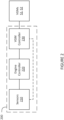
- the VGM controller 230 is composed of a VGM steady-state (VGMSS) unit 310, a VGM bias (VGMB) unit 320, a signal adder 330, a signal processing device 340, and a VGM control loop (VGMCL) 350.
- the VGM controller 230 is configured for transmitting, via the VGMCL 350, signals to the actuators in the VGMs 51, 52, to effect a change in their position and/or orientation.
- different VGM controllers 230 can be provided for each of the VGMs in the engine 10 in other embodiments, a single VGM controller 230 can control operation of multiple VGMs, for instance the VGMs 51, 52.
- the VGMSS unit 310 and the VGMB unit 320 are configured for providing different portions of a control signal, which are combined via the signal adder 330.
- the VGMSS unit 310 is configured for producing a first signal which is indicative of a requested setting for the VGM 51 based on a current steady-state operation condition for the engine 10
- the VGMB unit 320 is configured for producing a second signal which is indicative of a requested change for the setting of the VGM 51.
- the second signal is produced in response to a transition between operating conditions for the engine 10, for example acceleration, deceleration, changes in altitude, and the like.
- the first and second signals are then combined by the adder 330 to form a VGM position request signal.
- the VGM position request signal is then transmitted, via the signal processing device 340, to the VGM control loop 350, for controlling the VGM 51.
- the signal sent to the VGM 51 by the VGM controller 230 can be a voltage-encoded signal, in which the desired setting for the VGM 51 is set based on the voltage level of the signal.
- a higher voltage level can indicate that the requested setting for the VGM 51 is more open, and a lower voltage level can indicate that the requested setting for the VGM 51 is more closed.
- Other approaches are also considered.
- the VGMSS unit 310 produces the first signal having a voltage which substantially corresponds to the current setting for the VGM.
- the resultant combined signal i.e. the VGM position request signal
- the resultant combined signal indicates a new desired setting for the VGM 51. For instance, if the second signal produced by the VGMB unit 320 is negative, the resulting VGM position request signal will be lower than a previous value of the VGM position request signal, indicating that the engine controller 320 provided instructions which should result in a closing of the VGM 51.
- the resulting VGM position request signal will be higher than a previous value of the VGM position request signal, indicating that the engine controller 320 provided instructions which should result in an opening of the VGM.
- control schemes for instance using signals on carrier waves, using digital signals, or other approaches, are also considered.
- the VGMB unit 320 receives, as part of the instructions provided by the engine controller 220, a speed signal, which can be used as a basis for the first signal produced by the VGMSS unit 310, and the second signal produced by the VGMB unit 320.
- the VGMSS unit 310 and/or the VGMB unit 320 is provided with one or more lookup tables, maps, algorithms, and/or other types of mathematical relationships which allow the VGMSS unit 310 and/or the VGMB unit 320 to produce the first and/or the second signal based on the speed signal received from the engine controller 220.
- a speed signal it should be noted that other signals, for instance a power signal, a torque signal, a pressure signal and/or any other suitable signal, are also considered.
- the speed signal (or power, torque, etc. signal) received from the engine controller 220, or from the sensors 210 can, in certain instances, exhibit noise of various types, including white, Brownian, etc., jitter, and the like.
- small but expected variations in the speed signal are possible, despite not being indicative of actual changes in the requested speed for the engine 10. This can lead to the VGMSS unit 310 and/or the VGMB unit 320 continually producing slightly varying signals, despite the engine 10 operating substantially at steady-state, and no actual change in the VGM 51 position having been requested.
- the VGMSS unit 310 and/or the VGMB unit 320 can interpret the noise in the speed signal received from the engine controller 320 as instructions to effect changes in the position of the VGM 51, and therefore produce varying first or second signals indicative of these perceived changes. Due to the random nature of signal noise, this can result in increased wear on the actuators which move the VGM 51, and the VGM 51 itself, due to repeated and continuous changes in position.
- the combined signal provided by the adder 330 is then sent to the signal processing device 340.
- the adder 330 and the signal processing device 340 can be embodied as a single device.
- the signal processing device 340 is configured for processing the combined signal to mitigate the risk of continually adjusting the position, orientation, and the like, of the VGM 51, by removing, reducing, or mitigating the noise, dithering, and minor variations present in the combined signal, thereby producing a filtered signal.
- the signal processing device 340 then transmits the filtered signal to the VGM control loop 350, which is configured for operating the actuators of the VGM 51, as discussed hereinabove.
- the signal processing device 340 is configured for filtering the combined signal to remove portions of the signal which are considered noise.
- the signal processing device 340 evaluates the combined signal against a signal range for the combined signal: when variations over time in the combined signal are within the signal range, the variations are attributed to noise, and the signal processing device 340 performs one or more signal processing techniques to reject the variations. This is so that the movements effects produced by the VGMCL 350 based on the processed signal are smoother and more gradual, which can assist in reducing wear on the VGMs 51, 52.
- the signal range can be any suitable range, and can be centered at a current setting for the VGM 51, for instance based on the first signal produced by the VGMSS unit 310.
- the signal range can be 50 RPM centered at the current speed of the engine 10, based on the first signal. If the current speed of the engine is 500 RPM, any change in the speed of the engine between 475 and 525 RPM would fall within the signal range of 50 RPM, and would be rejected or processed by the signal processing device 340. Other examples, signal ranges, and the like, are also considered.
- the signal processing device 340 performs processing of the combined signal to remove the noise of the combined signal.
- the noise in the combined signal consists of high-frequency signal components: for instance, any signal portion having a frequency above 3, 5, or 10 Hz, or any other suitable value, can be considered noise.
- the signal processing device 340 can be configured for processing the combined signal provided by the adder 330 in any suitable fashion in order to mitigate the noise present in the combined signal due to the speed signal obtained at the VGMSS unit 310 and/or the VGMB unit 320, from the engine controller 220 and/or the sensors 210.
- the signal processing device 340 includes, or is substantially composed of, an electronic filter, which may be implemented using hardware or software.
- the filter can be embodied as a resistor-capacitor (RC) filter, a resistor-inductor (RL) filter, a resistor-inductor-capacitor (RLC) filter, a T filter, a ⁇ filter, and the like.
- the signal processing device 340 is configured for obtaining a digital representation of the combined signal, for instance via an analog-to-digital converter (ADC), for filtering the digital representation in software, and for producing the filtered signal as an analog signal, for instance via a digital-to-analog converter (DAC). Still other filtering approaches are considered.
- ADC analog-to-digital converter
- DAC digital-to-analog converter
- the filter may be any suitable type of filter, such as a first-order low-pass filter.
- the first-order low-pass filter can be designed to have a time constant selected for filtering the combined signal to remove noise, for example based on the frequency threshold associated with noise, as discussed hereinabove.
- the signal processing device 340 can additionally perform signal smoothing, noise reduction, signal modulation and/or demodulation, and the like.
- separate signal smoothing, noise reducing, or other devices can be incorporated into the VGM controller 230 and placed between the adder 330 and the signal processing device 340 to perform one or more signal pretreatment operations, prior to the signal processing device 340 receiving the combined signal.
- the signal processing device 340 includes, or is substantially composed of, a rate limiter circuit, or a device which implements rate-limiting functionality in software.
- the rate limiter circuit can be designed to have a characteristic rate-of-change and/or a dead-band selected for filtering the combined signal to remove noise.
- a software-based rate-limiter can have a similarly-selected characteristic rate-of-change and/or dead-band.
- the signal processing device 340 evaluates the combined signal against the signal range and determines that variations in the combined signal are not due to noise and/or minor variations in the signals from the sensors 210 and/or the engine controller 220, the signal processing device is configured for producing the processed signal and for providing the processed signal to the VGMCL 350, which is configured for interpreting the processed signal and for commanding operation of the VGM 51, for instance via actuators thereof.
- the VGMCL 350 can be a substantially analog device, which performs analog-domain signal processing to transform the processed signal into commands for the VGM 51.
- the VGMCL 350 can be implemented in software, for example as part of a full-authority digital engine controls (FADEC), and can produce via software the necessary commands for the VGM 51.
- FADEC full-authority digital engine controls
- the processed signal produced by the signal processing device 340 is a scaled version of the combined signal.
- the combined signal can be reduced based on the signal range such that the movements effects by the VGMCL 350 based on the processed signal are smoother when transitioning beyond a suitable range and more rapid albeit less accurate, which can assist in rapid tracking on the VGMs 51, 52.
- the combined signal is a speed-based signal measured in RPM
- the range can be expressed as 50 RPM.
- the processed signal can track the transition over subsequent sampling times by reducing the value of each subsequent RPM value by half the value of the signal range.
- the combined signal is sampled at 600 RPM, this can be reduced by 25 (half the signal range of 50 RPM) to 575 RPM.
- the actual transition in the VGMs 51, 52 commanded by the VGMCL 350 is offset, when compared to the combined signal, and the movement commanded in the VGMs 51, 52 is more rapid beyond the suitable range, thereby produced in the VGMs 51, 52 is smoother when transitioning back within the suitable range.
- the processed signal can be a time-delayed version of the combined signal.
- the processed signal can be a time-dilated version of the combined signal.
- the processing device 340 can perform one or more signal processing techniques when producing the processed signal, for instance interpolation or similar techniques.
- the signal processing device 340 is configured for being activated or deactivated based on one or more events.
- the signal processing device 340 can be active during certain portions of a flight mission of the aircraft.
- the signal processing device 340 can be activated in response to an activation signal, for instance as commanded by the engine controller 220, and can be deactivated in similar fashion. Still other events are considered.
- the VGM controller 230 is configured for controlling operation of the VGMs 51, 52, while substantially ignoring unrequested changes to the position and/or orientation of the VGMs 51, 52, induced by noisy power, torque, or other signals used during the production of the control signals for the VGMs 51, 52.
- position and “orientation”, as used herein, can be used interchangeably, and the use of one does not exclude the use of the other.
- a VGM position request signal is obtained.
- the VGM position request signal is indicative of a requested position change for a VGM, for instance one of the VGMs 51, 52.
- the VGM position request signal can be obtained, for instance, from the adder 330, which combines the first and second signals to produce the VGM position request signal based on instructions obtained from the engine controller 220.
- a noise level of the VGM position request signal is reduced and/or the VGM position request signal is smoothed, for instance via the signal processing device 340.
- the noise level reduction and/or smoothing can be implemented using any suitable techniques.
- the predetermined range can be, as described hereinabove, a range centered at a current value for the VGM position signal.
- the method moves to step 408.
- the variation of the VGM position signal is not within the predetermined range, the method moves to step 412.
- the VGM position request signal is filtered to reduce a level of noise in the VGM position request signal, thereby producing a filtered signal.
- the filtering can be performed by the signal processing device 340, and can comprise removing, reducing, or mitigating the noise and/or minor variations to produce the filtered signal.
- the filtered VGM position request signal is transmitted to a controller of the VGM, for example the VGMCL 350.
- the filtered VGM position request signal can be transmitted using any suitable protocol, and in any suitable format.
- a processed signal based on the VGM position request signal, is transmitted to a controller of the VGM, for example the VGMCL 350. Transmitting the processed signal comprises processing the signal to scale the signal based on the signal range.
- the processed signal can be a noise-reduced and/or smoothed version of the VGM position request signal, or a delayed, time-dilated, interpolated, or other signal which has been processed to produce a smoother and/or more gradual movement in the VGMs 51, 52.
- the method 400 may be implemented by a computing device 510, comprising a processing unit 512 and a memory 514 which has stored therein computer-executable instructions 516.
- the processing unit 512 may comprise any suitable devices configured to implement the method 400 such that instructions 516, when executed by the computing device 510 or other programmable apparatus, may cause the functions/acts/steps performed as part of the method 400 as described herein to be executed.
- the processing unit 512 may comprise, for example, any type of general-purpose microprocessor or microcontroller, a digital signal processing (DSP) processor, a central processing unit (CPU), an integrated circuit, a field programmable gate array (FPGA), a reconfigurable processor, other suitably programmed or programmable logic circuits, or any combination thereof.
- DSP digital signal processing
- CPU central processing unit
- FPGA field programmable gate array
- reconfigurable processor other suitably programmed or programmable logic circuits, or any combination thereof.
- the memory 514 may comprise any suitable known or other machine-readable storage medium.
- the memory 514 may comprise non-transitory computer readable storage medium, for example, but not limited to, an electronic, magnetic, optical, electromagnetic, infrared, or semiconductor system, apparatus, or device, or any suitable combination of the foregoing.
- the memory 514 may include a suitable combination of any type of computer memory that is located either internally or externally to device, for example random-access memory (RAM), read-only memory (ROM), compact disc read-only memory (CDROM), electro-optical memory, magnetooptical memory, erasable programmable read-only memory (EPROM), and electrically-erasable programmable read-only memory (EEPROM), Ferroelectric RAM (FRAM) or the like.
- Memory 514 may comprise any storage means (e.g., devices) suitable for retrievably storing machine-readable instructions 516 executable by processing unit 512.
- engine controller 220 may be implemented as part of a full-authority digital engine controls (FADEC) or other similar device, including electronic engine control (EEC), engine control unit (EUC), various actuators, and the like.
- FADEC full-authority digital engine controls
- EEC electronic engine control
- EUC engine control unit
- various actuators and the like.
- the methods and systems for controlling operation of a VGM of an aircraft engine described herein may be implemented in a high level procedural or object oriented programming or scripting language, or a combination thereof, to communicate with or assist in the operation of a computer system, for example the computing device 510.
- the methods and systems described herein may be implemented in assembly or machine language.
- the language may be a compiled or interpreted language.
- Program code for implementing the methods and systems described herein may be stored on a storage media or a device, for example a ROM, a magnetic disk, an optical disc, a flash drive, or any other suitable storage media or device.
- the program code may be readable by a general or special-purpose programmable computer for configuring and operating the computer when the storage media or device is read by the computer to perform the procedures described herein.
- Embodiments of the methods and systems described herein may also be considered to be implemented by way of a non-transitory computer-readable storage medium having a computer program stored thereon.
- the computer program may comprise computer-readable instructions which cause a computer, or more specifically the processing unit 512 of the computing device 510, to operate in a specific and predefined manner to perform the functions described herein, for example those described in the method 400.
- Computer-executable instructions may be in many forms, including program modules, executed by one or more computers or other devices.
- program modules include routines, programs, objects, components, data structures, etc., that perform particular tasks or implement particular abstract data types.
- functionality of the program modules may be combined or distributed as desired in various embodiments.
Landscapes
- Engineering & Computer Science (AREA)
- Chemical & Material Sciences (AREA)
- Combustion & Propulsion (AREA)
- Mechanical Engineering (AREA)
- General Engineering & Computer Science (AREA)
- Physics & Mathematics (AREA)
- Geometry (AREA)
- Fluid Mechanics (AREA)
- Combined Controls Of Internal Combustion Engines (AREA)
- Feedback Control In General (AREA)
Description
- The present disclosure relates generally to gas turbine engines, and more particularly to control of variable geometry mechanisms (VGMs) in gas turbine engines.
- During aircraft operations consisting of rapid engine transitions from low to high power levels, it is desirable to reduce the response time of the engine in order to achieve a required power. For this purpose, inlet mass flow can be increased by accelerating the gas generator of the engine, thereby increasing the engine's power. This may be achieved by a variety of techniques which adjust the shape or geometry of one or more components of the engine, called variable geometry mechanisms, thereby adjusting the response of the engine.
- Various control approaches for variable geometry mechanisms are known, for example based on the speed or the torque of the engine. However, reliance on these values can lead to excessive wear on the mechanical components of the variable geometry mechanisms. There is therefore a need for improved control schemes for variable geometry mechanisms.
- A prior art signal processing device having the features of the preamble of claim 1 is disclosed in
US 5 313 778 A . Further prior art signal processing devices are disclosed inUS 2014/278014 A1 ,US 2010/0281875 A1 andUS 6 231 306 B1 . - In accordance with an aspect of the present invention, there is provided a signal processing device for use in an aircraft engine with a variable geometry mechanism (VGM), as set forth in claim 1.
- In an embodiment according to the previous embodiment, wherein filtering the VGM position request signal comprises subjecting the VGM position request signal to a first-order low-pass filter having a predetermined time constant selected for filtering noise above a predetermined frequency threshold.
- In an embodiment according to any of the previous embodiments, wherein filtering the VGM position request signal comprises subjecting the VGM position request signal to a rate limiter.
- In an embodiment according to any of the previous embodiments, the rate limiter is configured to have a predetermined rate of change selected for filtering noise above a predetermined frequency threshold.
- In an embodiment according to any of the previous embodiments, the rate limiter is configured to have a predetermined dead band selected for filtering noise above a predetermined frequency threshold.
- In an embodiment according to any of the previous embodiments, the program instructions are further executable by the processing unit for at least one of reducing a noise level of the VGM position request signal and smoothing the VGM position request signal.
- In an embodiment according to any of the previous embodiments, scaling the VGM position request signal by a factor associated with the predetermined range comprises reducing each of a plurality of subsequent values of the VGM position request signal by half of the value of the predetermined range.
- In an embodiment according to any of the previous embodiments, the VGM position request signal is based on one of a power and a speed of the aircraft engine.
- In an embodiment according to any of the previous embodiments, the program instructions are further executable by the processing unit for receiving an activation signal from an engine controller associated with the aircraft engine, wherein the filtering occurs responsive to the activation signal.
- In accordance with another aspect of the present invention, there is provided a method for processing a control signal for a variable geometry mechanism (VGM) of an aircraft engine, as set forth in claim 8.
- In an embodiment, the method is carried out by a signal processing device, which may be for use in an aircraft engine.
- In an embodiment according to any of the previous embodiments, filtering the VGM position request signal comprises subjecting the VGM position request signal to a first-order low-pass filter having a predetermined time constant selected for filtering noise above a predetermined frequency threshold.
- In an embodiment according to any of the previous embodiments, filtering the VGM position request signal comprises subjecting the VGM position request signal to a rate limiter configured to have a predetermined rate of change selected for filtering noise above a predetermined frequency threshold.
- In an embodiment according to any of the previous embodiments, filtering the VGM position request signal comprises subjecting the VGM position request signal to a rate limiter configured to have a predetermined dead band selected for filtering noise above a predetermined frequency threshold.
- In an embodiment according to any of the previous embodiments, the method further comprises at least one of reducing a noise level of the VGM position request signal and smoothing the VGM position request signal.
- In an embodiment according to any of the previous embodiments, the VGM position request signal is based on one of a power and a speed of the aircraft engine.
- In an embodiment according to any of the previous embodiments, the method further comprises receiving an activation signal from an engine controller associated with the aircraft engine, wherein the filtering occurs responsive to the activation signal.
- In accordance with a still further aspect of the present invention, there is provided a control system for a variable geometry mechanism (VGM) of an engine, as set forth in
claim 15. - Reference is now made to the accompanying figures in which:
-
Figure 1 is a schematic cross-sectional view of an example gas turbine engine; -
Figure 2 is a block diagram of an example control system for the engine ofFigure 1 ; -
Figure 3 is a block diagram of an embodiment of a variable geometry mechanism controller; -
Figure 4 is a flowchart illustrating an example method for controlling operation of a variable geometry mechanism, in accordance with an embodiment; and -
Figure 5 is a block diagram of an example computer system for implementing the method ofFigure 4 . - It will be noted that throughout the appended drawings, like features are identified by like reference numerals.
-
Figure 1 illustrates agas turbine engine 10 of a type preferably provided for use in subsonic flight, generally comprising in serial flow communication anair inlet 11, acompressor section 12 for pressurizing the air from theair inlet 11, acombustor 13 in which the compressed air is mixed with fuel and ignited for generating an annular stream of hot combustion gases, aturbine section 14 for extracting energy from the combustion gases, anexhaust outlet 15 through which the combustion gases exit thegas turbine engine 10. Theengine 10 includes apropeller 16 which provides thrust for flight and taxiing. Thegas turbine engine 10 has alongitudinal center axis 17. - The gas turbine engine 10 (sometimes referred to herein simply as "
engine 10") has acentral core 18 defining a gas path through which gases flow as depicted by flow arrows inFig. 1 . The illustratedengine 10 is a "reverse-flow"engine 10 because gases flow through thecore 18 from theair inlet 11 at a rear portion thereof, to theexhaust outlet 15 at a front portion thereof. This is in contrast to "through-flow" gas turbine engines in which gases flow through the core of the engine from a front portion to a rear portion. The direction of the flow of gases through thecore 18 of theengine 10 disclosed herein can be better appreciated by considering that the gases flow through thecore 18 in the same direction D as the one along which theengine 10 travels during flight. Stated differently, gases flow through theengine 10 from a rear end thereof towards thepropeller 16. - Although illustrated as a turboprop engine, the
gas turbine engine 10 may alternatively be another type of engine, for example a turbofan engine, also generally comprising in serial flow communication a compressor section, a combustor, and a turbine section, and a fan through which ambient air is propelled. A turboshaft engine may also apply. Similarly, although illustrated as a reverse-flow engine, the techniques described herein can also be applied to through-flow engines. In addition, although theengine 10 is described herein for flight applications, it should be understood that other uses, such as industrial or the like, may apply. - Still referring to
Figure 1 , theengine 10 has multiple spools which perform compression to pressurize the air received through theair inlet 11, and which extract energy from the combustion gases before they exit thecore 18 via theexhaust outlet 15. According to the illustrated example, theengine 10 is provided in the form of a multi-spool engine having a low pressure (LP)spool 20 and a high pressure (HP) spool 40 independently rotatable aboutaxis 17. However, it is understood that a multi-spool engine could have more than two spools. It should also be noted that the embodiments described herein also consider the use of single-spool engines. - The
LP spool 20 includes at least one component to compress the air that is part of thecompressor section 12, and at least one component to extract energy from the combustion gases that is part of theturbine section 14. More particularly, theLP spool 20 has alow pressure turbine 21 which extracts energy from the combustion gases, and which is drivingly engaged to anLP compressor 22 for pressurizing the air. The LP turbine 21 (also referred to as the power turbine) drives theLP compressor 22, thereby causing theLP compressor 22 to pressurize the air. Both theLP turbine 21 and theLP compressor 22 are disposed along theaxis 17. In the depicted embodiment, both theLP turbine 21 and theLP compressor 22 are axial rotatable components having an axis of rotation that is coaxial with thecenter axis 17. They can include one or more stages, depending upon the desired engine thermodynamic cycle, for example. - In the depicted embodiment, the
LP spool 20 has apower shaft 23 which mechanically couples theLP turbine 21 and theLP compressor 22, and extends axially between them. Theshaft 23 is coaxial with thecentral axis 17 of theengine 10. Theshaft 23 allows theLP turbine 21 to drive theLP compressor 22 during operation of theengine 10. Theshaft 23 is not limited to the configuration depicted inFig. 1 , and can also mechanically couple theLP turbine 21 and theLP compressor 22 in any other suitable way provided that it transmits a rotational drive from theLP turbine 21 to theLP compressor 22. For example, theshaft 23 can be combined with a gearedLP compressor 22 to allow theLP compressor 22 to run at a different rotational speed from theLP turbine 21. This can provide more flexibility in the selection of design points for the LP compressor. - Still referring to
Figure 1 , theengine 10 includes anoutput drive shaft 24. Thedrive shaft 24 extends forwardly from theLP turbine 21 and is drivingly engaged thereto. In the illustrated example, thedrive shaft 24 is distinct from thepower shaft 23 and mechanically coupled thereto to be driven by theLP turbine 21. In the depicted embodiment, thedrive shaft 24 and thepower shaft 23 are coaxial and interconnected.Figure 1 shows that the power and driveshafts spline 25. Thespline 25, which can include ridges or teeth on thedrive shaft 24 that mesh with grooves in the power shaft 23 (or vice versa), allows for the transfer of torque between thedrive shaft 24 and thepower shaft 23. In the depicted embodiment, thepower shaft 23 lies at least partially within thedrive shaft 24, such that thespline 25 transfers the rotational drive or torque generated by theLP turbine 21 from thedrive shaft 24 to thepower shaft 23. Thespline 25 can operate so that thepower shaft 23 and thedrive shaft 24 rotate at the same rotational speed. Other mechanical techniques can also be used to interconnect the power and driveshafts shafts drive shaft 24 and thepower shaft 23 are also possible. For example, thedrive shaft 24 and thepower shaft 23 can be a single shaft driven by theLP turbine 21. Thedrive shaft 24 therefore transfers the rotational output of theLP turbine 21 in a forward direction to drive another component. - A rotatable load, which in the embodiment shown includes the
propeller 16, is mountable to theengine 10, and when mounted, is drivingly engaged to theLP turbine 21, and is located forward of theLP turbine 21. In such a configuration, during operation of theengine 10, theLP turbine 21 drives the rotatable load such that a rotational drive produced by theLP turbine 21 is transferred to the rotatable load. The rotatable load can therefore be any suitable component, or any combination of suitable components, that is capable of receiving the rotational drive from theLP turbine 21, as now described. - In the embodiment shown, a reduction gearbox 31 (sometimes referred to herein simply as "
RGB 31") is mechanically coupled to a front end of thedrive shaft 24, which extends between theRGB 31 and theLP turbine 21. TheRGB 31 processes and outputs the rotational drive transferred thereto from theLP turbine 21 via thedrive shaft 24 through known gear reduction techniques. TheRGB 31 allows for thepropeller 16 to be driven at its optimal rotational speed, which is different from the rotational speed of theLP turbine 21. - Still referring to
Figure 1 , the HP spool 40 with at least one component to compress the air that is part of thecompressor section 12, and at least one component to extract energy from the combustion gases that is part of theturbine section 14. The HP spool 40 is also disposed along theaxis 17 and includes an HP turbine 41 drivingly engaged (e.g. directly connected) to ahigh pressure compressor 42 by anHP shaft 43 rotating independently of thepower shaft 23. Similarly to theLP turbine 21 and theLP compressor 22, the HP turbine 41 and theHP compressor 42 can include various stages of axial rotary components. In the depicted embodiment, theHP compressor 42 includes acentrifugal compressor 42A or impeller and anaxial compressor 42B, both of which are driven by the HP turbine 41. During operation of theengine 10, the HP turbine 41 drives theHP compressor 42. - It can thus be appreciated that the presence of the above-described LP and HP spools 20, 40 provides the
engine 10 with a "split compressor" arrangement. More particularly, some of the work required to compress the incoming air is transferred from theHP compressor 42 to theLP compressor 22. In other words, some of the compression work is transferred from the HP turbine 41 to the moreefficient LP turbine 21. This transfer of work may contribute to higher pressure ratios while maintaining a relatively small number of rotors. In a particular embodiment, higher pressure ratios allow for higher power density, better engine specific fuel consumption (SFC), and a lower turbine inlet temperature (sometimes referred to as "T4") for a given power. These factors can contribute to a lower overall weight for theengine 10. The transfer of compression work from theHP compressor 42 to theLP compressor 22 contrasts with some conventional reverse-flow engines, in which the high pressure compressor (and thus the high pressure turbine) perform all of the compression work. - In light of the preceding, it can be appreciated that the
LP turbine 21 is the "low-speed" and "low pressure" turbine when compared to the HP turbine 41. TheLP turbine 21 is sometimes referred to as a "power turbine". The turbine rotors of the HP turbine 41 spin at a higher rotational speed than the turbine rotors of theLP turbine 21 given the closer proximity of the HP turbine 41 to the outlet of thecombustor 13. Consequently, the compressor rotors of theHP compressor 42 may rotate at a higher rotational speed than the compressor rotors of theLP compressor 22. Theengine 10 shown inFig. 1 is thus a "two-spool"engine 10. - The HP turbine 41 and the
HP compressor 42 can have any suitable mechanical arrangement to achieve the above-described split compressor functionality. For example, and as shown inFig. 1 , the HP spool 40 includes ahigh pressure shaft 43 extending between theHP compressor 42 and the HP turbine section 41. Thehigh pressure shaft 43 is coaxial with thepower shaft 23 and rotatable relative thereto. The relative rotation between thehigh pressure shaft 43 and thepower shaft 23 allow theshafts HP compressor 42 and theLP compressor 22 to rotate at different rotational speeds. TheHP shaft 43 can be mechanically supported by thepower shaft 23 using bearings or the like. In the depicted embodiment, thepower shaft 23 is at least partially disposed within theHP shaft 43. - The split compressor arrangement also allows bleed air to be drawn from between the
HP compressor 42 and theLP compressor 22. More particularly, in the embodiment ofFig. 1 , theengine 10 includes aninter-stage bleed 44 port or valve that is aft of theHP compressor 42 and forward of theLP compressor 22, which may provide for increased flexibility in the available bleed pressures. In a particular embodiment, the bleed pressure design point of theinter-stage bleed 44 is selected based on the pressure ratio of theLP compressor 22, which runs independently from theHP compressor 42. For operability, variable inlet guide vanes (VIGV) 51 and variable guide vanes (VGV) 52 can be used on theLP compressor 22 and at the entry of theHP compressor 42, together with theinter-stage bleed 44. - It should be noted that the engine of
Figure 1 represents only one example engine, and that the embodiments described herein can be applied to any other suitable manner of engine. - The
engine 10 includes one or more variable geometry mechanisms (VGMs) which may assist in achieving optimized engine transient response. In some embodiments, the VGMs consists of one or more VGVs, for instance the VIGV 51 and theVGV 52, which may be one of inlet compressor guide vanes for directing air into thecompressor section 12, outlet guide vanes for directing air out of thecompressor section 12, variable stator vanes for directing incoming air into rotor blades of theengine 10, and/or one or more variable nozzles, variable bleed-off valves, for instance theinter-stage bleed 44, and the like. It should be understood that one or more of the above-mentioned VGMs may be adjusted for the purpose of decreasing the response time of theengine 10 during rapid engine transitions, e.g. from low to high power levels, or vice-versa. Indeed, adjustment of the position (e.g. the angle) of the VGMs can impact the inlet mass flow to theengine 10, and in turn allow theengine 10 to operate at a required power. - In some embodiments, as illustrated in
Figure 1 , theengine 10 has a dual compression system with a low-spool compression system (LPC), including theLP spool 20, and a high-spool compression system (HPC), including the HP spool 40, which are separate from one-another. The VGMs include the VIGV 51 at theair inlet 11 near the LPC and theVGVs 52 upstream of the HPC. It should be noted that other VGMs may also be included for both the LPC and the HPC. In other embodiments, theengine 10 includes only one compression system, and includes fewer or more VGMs. - With reference to
Figure 2 , an embodiment of anengine control system 200 for theengine 10 is illustrated. Theengine control system 200 includes one ormore sensors 210, anengine controller 220, and aVGM controller 230. Thesensors 210 are coupled to theengine controller 220, which in turn is coupled to theVGM controller 230. In some embodiments, some of thesensors 210 are also coupled to theVGM controller 230. Theengine controller 220, and optionally theVGM controller 230, are configured for obtaining various inputs from thesensors 210. - The
engine controller 220 can be communicatively coupled to any number of systems for effecting control of theengine 10. For instance, the engine controller can be coupled to fuel flow valves, gear actuators, and the like. TheVGM controller 230 is communicatively coupled to theVGMs 51, 52, and any other VGMs of theengine 10, for issuing commands thereto, for instance to control positions of theVGMs 51, 52. Although theengine control system 200 inFigure 2 is illustrated as including only thesensors 210, theengine controller 220, and theVGM controller 230, it should be noted that practical applications of theengine control system 200 may include any number of other suitable components and controllers. - The
sensors 210 are configured for acquiring various data about theengine 10 and the aircraft in which theengine 10 operates. Thesensors 210 can be disposed throughout theengine 10 and/or the aircraft, and can be configured for measuring any suitable information about the operation of theengine 10 and/or the aircraft. Thesensors 210 can include pressure sensors, temperature sensors, rotation sensors, speed sensors, accelerometers, gyrosensors, and the like. In some embodiments, thesensors 210 include one or more virtual sensors, which use other measurements to derive a desired value, for example in software. - The
engine controller 220 is configured for controlling operation of theengine 10. This can include modulating a fuel flow to the engine, adjusting various operational parameters of the engine, for instance a gearing of theRGB 31, and the like. In some embodiments, theengine controller 220 is configured for altering the operation of one or more VGMs, for example the VIGV 51 and theVGV 52, via theVGM controller 230. For example, theengine controller 220 can send instructions to theVGM controller 230 indicative of desired changes in engine operating conditions: for instance, theengine controller 220 can request changes relating to temperature, pressure, and the like. TheVGM controller 230 is configured for interpreting the instructions from theengine controller 220 and causing suitable changes to the position and/or orientation of theVGMs 51, 52 to enact the requested changes to the engine operating conditions. In other embodiments, theVGM controller 230 obtains various inputs from thesensors 210 indicating changes in the operating conditions of theengine 10, and determines based thereon corresponding changes to the operating conditions of theVGMs 51, 52, to be implemented. - The
VGM controller 230 is configured for issuing commands to theVGMs 51, 52 in order to effect changes in the position, orientation, and the like, of theVGMs 51, 52. In some embodiments, theVGM controller 230 issues the commands to motors, actuators, or similar active elements of theVGMs 51, 52, to cause movement in theVGMs 51, 52, in line with the instructions received by theVGM controller 230 from theengine controller 220. For example, a position of the VIGV 51 and/or theVGV 52, an orientation of the VIGV 51 and/or theVGV 52, a degree of openness of an aperture formed by the VIGV 51 and/or theVGV 52, and/or any other suitable aspects of the VIGV 51 and/or theVGV 52 can be adjusted. In another example, the position and/or a degree of openness of a variable bleed-off valve can be adjusted. Still other embodiments, involving one of inlet compressor guide vanes for directing air into thecompressor section 12, outlet guide vanes for directing air out of thecompressor section 12, variable stator vanes for directing incoming air into rotor blades of theengine 10, and/or one or more variable nozzles, variable bleed-off valves, for instance theinter-stage bleed 44, and the like, are also considered. - With reference to
Figure 3 , an embodiment of theVGM controller 230 is illustrated. TheVGM controller 230 is composed of a VGM steady-state (VGMSS)unit 310, a VGM bias (VGMB)unit 320, asignal adder 330, asignal processing device 340, and a VGM control loop (VGMCL) 350. TheVGM controller 230 is configured for transmitting, via theVGMCL 350, signals to the actuators in theVGMs 51, 52, to effect a change in their position and/or orientation. In some embodiments,different VGM controllers 230 can be provided for each of the VGMs in theengine 10 in other embodiments, asingle VGM controller 230 can control operation of multiple VGMs, for instance theVGMs 51, 52. Although the foregoing discussion focuses only on a single VGM 51, is should be understood that the same notions could be applied to a multi-VGM system. - The
VGMSS unit 310 and theVGMB unit 320 are configured for providing different portions of a control signal, which are combined via thesignal adder 330. TheVGMSS unit 310 is configured for producing a first signal which is indicative of a requested setting for the VGM 51 based on a current steady-state operation condition for theengine 10, and theVGMB unit 320 is configured for producing a second signal which is indicative of a requested change for the setting of the VGM 51. In some embodiments, the second signal is produced in response to a transition between operating conditions for theengine 10, for example acceleration, deceleration, changes in altitude, and the like. - The first and second signals are then combined by the
adder 330 to form a VGM position request signal. The VGM position request signal is then transmitted, via thesignal processing device 340, to theVGM control loop 350, for controlling the VGM 51. For example, the signal sent to the VGM 51 by theVGM controller 230 can be a voltage-encoded signal, in which the desired setting for the VGM 51 is set based on the voltage level of the signal. In one particular control scheme, a higher voltage level can indicate that the requested setting for the VGM 51 is more open, and a lower voltage level can indicate that the requested setting for the VGM 51 is more closed. Other approaches are also considered. - The
VGMSS unit 310 produces the first signal having a voltage which substantially corresponds to the current setting for the VGM. By adding the second signal produced by theVGMB unit 320, via theadder 330, to the first signal produced by theVGMSS unit 310, the resultant combined signal (i.e. the VGM position request signal) indicates a new desired setting for the VGM 51. For instance, if the second signal produced by theVGMB unit 320 is negative, the resulting VGM position request signal will be lower than a previous value of the VGM position request signal, indicating that theengine controller 320 provided instructions which should result in a closing of the VGM 51. Conversely, if the second signal produced by theVGMB unit 320 is positive, the resulting VGM position request signal will be higher than a previous value of the VGM position request signal, indicating that theengine controller 320 provided instructions which should result in an opening of the VGM. Of course, other control schemes, for instance using signals on carrier waves, using digital signals, or other approaches, are also considered. - In some embodiments, the
VGMB unit 320 receives, as part of the instructions provided by theengine controller 220, a speed signal, which can be used as a basis for the first signal produced by theVGMSS unit 310, and the second signal produced by theVGMB unit 320. In some embodiments, theVGMSS unit 310 and/or theVGMB unit 320 is provided with one or more lookup tables, maps, algorithms, and/or other types of mathematical relationships which allow theVGMSS unit 310 and/or theVGMB unit 320 to produce the first and/or the second signal based on the speed signal received from theengine controller 220. Although the present discussion focuses primarily on the use of a speed signal, it should be noted that other signals, for instance a power signal, a torque signal, a pressure signal and/or any other suitable signal, are also considered. - However, the speed signal (or power, torque, etc. signal) received from the
engine controller 220, or from thesensors 210, can, in certain instances, exhibit noise of various types, including white, Brownian, etc., jitter, and the like. In addition, small but expected variations in the speed signal are possible, despite not being indicative of actual changes in the requested speed for theengine 10. This can lead to theVGMSS unit 310 and/or theVGMB unit 320 continually producing slightly varying signals, despite theengine 10 operating substantially at steady-state, and no actual change in the VGM 51 position having been requested. Put differently, theVGMSS unit 310 and/or theVGMB unit 320 can interpret the noise in the speed signal received from theengine controller 320 as instructions to effect changes in the position of the VGM 51, and therefore produce varying first or second signals indicative of these perceived changes. Due to the random nature of signal noise, this can result in increased wear on the actuators which move the VGM 51, and the VGM 51 itself, due to repeated and continuous changes in position. - To address this issue, the combined signal provided by the
adder 330 is then sent to thesignal processing device 340. It should be noted that in some embodiments, theadder 330 and thesignal processing device 340 can be embodied as a single device. Thesignal processing device 340 is configured for processing the combined signal to mitigate the risk of continually adjusting the position, orientation, and the like, of the VGM 51, by removing, reducing, or mitigating the noise, dithering, and minor variations present in the combined signal, thereby producing a filtered signal. Thesignal processing device 340 then transmits the filtered signal to theVGM control loop 350, which is configured for operating the actuators of the VGM 51, as discussed hereinabove. In some embodiments, thesignal processing device 340 is configured for filtering the combined signal to remove portions of the signal which are considered noise. - The
signal processing device 340 evaluates the combined signal against a signal range for the combined signal: when variations over time in the combined signal are within the signal range, the variations are attributed to noise, and thesignal processing device 340 performs one or more signal processing techniques to reject the variations. This is so that the movements effects produced by theVGMCL 350 based on the processed signal are smoother and more gradual, which can assist in reducing wear on theVGMs 51, 52. The signal range can be any suitable range, and can be centered at a current setting for the VGM 51, for instance based on the first signal produced by theVGMSS unit 310. For example, if theVGMSS unit 310 and theVGMB unit 320 use a speed signal (expressed as revolutions-per-minute, or RPM) as a basis for controlling operation of the VGM 51, the signal range can be 50 RPM centered at the current speed of theengine 10, based on the first signal. If the current speed of the engine is 500 RPM, any change in the speed of the engine between 475 and 525 RPM would fall within the signal range of 50 RPM, and would be rejected or processed by thesignal processing device 340. Other examples, signal ranges, and the like, are also considered. - When changes in the combined signal from one sampling time to a subsequent sampling time fall within the signal range, the changes can be considered noise and/or minor variations. In response, the
signal processing device 340 performs processing of the combined signal to remove the noise of the combined signal. In some embodiments, the noise in the combined signal consists of high-frequency signal components: for instance, any signal portion having a frequency above 3, 5, or 10 Hz, or any other suitable value, can be considered noise. - The
signal processing device 340 can be configured for processing the combined signal provided by theadder 330 in any suitable fashion in order to mitigate the noise present in the combined signal due to the speed signal obtained at theVGMSS unit 310 and/or theVGMB unit 320, from theengine controller 220 and/or thesensors 210. In some embodiments, thesignal processing device 340 includes, or is substantially composed of, an electronic filter, which may be implemented using hardware or software. For example, the filter can be embodied as a resistor-capacitor (RC) filter, a resistor-inductor (RL) filter, a resistor-inductor-capacitor (RLC) filter, a T filter, a π filter, and the like. In another example, thesignal processing device 340 is configured for obtaining a digital representation of the combined signal, for instance via an analog-to-digital converter (ADC), for filtering the digital representation in software, and for producing the filtered signal as an analog signal, for instance via a digital-to-analog converter (DAC). Still other filtering approaches are considered. - Whether implemented in hardware or software, the filter may be any suitable type of filter, such as a first-order low-pass filter. For example, the first-order low-pass filter can be designed to have a time constant selected for filtering the combined signal to remove noise, for example based on the frequency threshold associated with noise, as discussed hereinabove. In some embodiments, the
signal processing device 340 can additionally perform signal smoothing, noise reduction, signal modulation and/or demodulation, and the like. Alternatively, separate signal smoothing, noise reducing, or other devices can be incorporated into theVGM controller 230 and placed between theadder 330 and thesignal processing device 340 to perform one or more signal pretreatment operations, prior to thesignal processing device 340 receiving the combined signal. - In other embodiments, the
signal processing device 340 includes, or is substantially composed of, a rate limiter circuit, or a device which implements rate-limiting functionality in software. The rate limiter circuit can be designed to have a characteristic rate-of-change and/or a dead-band selected for filtering the combined signal to remove noise. A software-based rate-limiter can have a similarly-selected characteristic rate-of-change and/or dead-band. - When the
signal processing device 340 evaluates the combined signal against the signal range and determines that variations in the combined signal are not due to noise and/or minor variations in the signals from thesensors 210 and/or theengine controller 220, the signal processing device is configured for producing the processed signal and for providing the processed signal to theVGMCL 350, which is configured for interpreting the processed signal and for commanding operation of the VGM 51, for instance via actuators thereof. TheVGMCL 350 can be a substantially analog device, which performs analog-domain signal processing to transform the processed signal into commands for the VGM 51. Alternatively, theVGMCL 350 can be implemented in software, for example as part of a full-authority digital engine controls (FADEC), and can produce via software the necessary commands for the VGM 51. - The processed signal produced by the
signal processing device 340 is a scaled version of the combined signal. The combined signal can be reduced based on the signal range such that the movements effects by theVGMCL 350 based on the processed signal are smoother when transitioning beyond a suitable range and more rapid albeit less accurate, which can assist in rapid tracking on theVGMs 51, 52. In an example in which the combined signal is a speed-based signal measured in RPM, the range can be expressed as 50 RPM. In the case of a transition from 500 RPM to 800 RPM, the processed signal can track the transition over subsequent sampling times by reducing the value of each subsequent RPM value by half the value of the signal range. For instance, if the combined signal is sampled at 600 RPM, this can be reduced by 25 (half the signal range of 50 RPM) to 575 RPM. In this fashion, the actual transition in theVGMs 51, 52 commanded by theVGMCL 350 is offset, when compared to the combined signal, and the movement commanded in theVGMs 51, 52 is more rapid beyond the suitable range, thereby produced in theVGMs 51, 52 is smoother when transitioning back within the suitable range. - It should be noted that other approaches for producing the processed signal as a scaled version of the combined signal are considered. For example, the processed signal can be a time-delayed version of the combined signal. In another example, the processed signal can be a time-dilated version of the combined signal. In a further example, the
processing device 340 can perform one or more signal processing techniques when producing the processed signal, for instance interpolation or similar techniques. - In some embodiments, the
signal processing device 340 is configured for being activated or deactivated based on one or more events. For example, thesignal processing device 340 can be active during certain portions of a flight mission of the aircraft. In another example, thesignal processing device 340 can be activated in response to an activation signal, for instance as commanded by theengine controller 220, and can be deactivated in similar fashion. Still other events are considered. - As such, the
VGM controller 230 is configured for controlling operation of theVGMs 51, 52, while substantially ignoring unrequested changes to the position and/or orientation of theVGMs 51, 52, induced by noisy power, torque, or other signals used during the production of the control signals for theVGMs 51, 52. It should be noted that the terms "position" and "orientation", as used herein, can be used interchangeably, and the use of one does not exclude the use of the other. - With reference to
Figure 4 , there is provided amethod 400 for controlling operation of theVGMs 51, 52. Atstep 402, a VGM position request signal is obtained. The VGM position request signal is indicative of a requested position change for a VGM, for instance one of theVGMs 51, 52. The VGM position request signal can be obtained, for instance, from theadder 330, which combines the first and second signals to produce the VGM position request signal based on instructions obtained from theengine controller 220. - Optionally, at step 404, a noise level of the VGM position request signal is reduced and/or the VGM position request signal is smoothed, for instance via the
signal processing device 340. The noise level reduction and/or smoothing can be implemented using any suitable techniques. - At
decision step 406, a determination is made regarding whether a variation of the VGM position signal is within a predetermined range. The predetermined range can be, as described hereinabove, a range centered at a current value for the VGM position signal. When the variation of the VGM position signal is within the predetermined range, the method moves to step 408. When the variation of the VGM position signal is not within the predetermined range, the method moves to step 412. - At
step 408, the VGM position request signal is filtered to reduce a level of noise in the VGM position request signal, thereby producing a filtered signal. For example, the filtering can be performed by thesignal processing device 340, and can comprise removing, reducing, or mitigating the noise and/or minor variations to produce the filtered signal. - At
step 410, the filtered VGM position request signal is transmitted to a controller of the VGM, for example theVGMCL 350. The filtered VGM position request signal can be transmitted using any suitable protocol, and in any suitable format. - When the determination performed at
step 406 indicates that the variation of the VGM position request signal is outside the predetermined range, themethod 400 moves to step 412. Atstep 412, a processed signal, based on the VGM position request signal, is transmitted to a controller of the VGM, for example theVGMCL 350. Transmitting the processed signal comprises processing the signal to scale the signal based on the signal range. The processed signal can be a noise-reduced and/or smoothed version of the VGM position request signal, or a delayed, time-dilated, interpolated, or other signal which has been processed to produce a smoother and/or more gradual movement in theVGMs 51, 52. - With reference to
Figure 5 , themethod 400 may be implemented by acomputing device 510, comprising aprocessing unit 512 and amemory 514 which has stored therein computer-executable instructions 516. Theprocessing unit 512 may comprise any suitable devices configured to implement themethod 400 such thatinstructions 516, when executed by thecomputing device 510 or other programmable apparatus, may cause the functions/acts/steps performed as part of themethod 400 as described herein to be executed. Theprocessing unit 512 may comprise, for example, any type of general-purpose microprocessor or microcontroller, a digital signal processing (DSP) processor, a central processing unit (CPU), an integrated circuit, a field programmable gate array (FPGA), a reconfigurable processor, other suitably programmed or programmable logic circuits, or any combination thereof. - The
memory 514 may comprise any suitable known or other machine-readable storage medium. Thememory 514 may comprise non-transitory computer readable storage medium, for example, but not limited to, an electronic, magnetic, optical, electromagnetic, infrared, or semiconductor system, apparatus, or device, or any suitable combination of the foregoing. Thememory 514 may include a suitable combination of any type of computer memory that is located either internally or externally to device, for example random-access memory (RAM), read-only memory (ROM), compact disc read-only memory (CDROM), electro-optical memory, magnetooptical memory, erasable programmable read-only memory (EPROM), and electrically-erasable programmable read-only memory (EEPROM), Ferroelectric RAM (FRAM) or the like.Memory 514 may comprise any storage means (e.g., devices) suitable for retrievably storing machine-readable instructions 516 executable by processingunit 512. - It should be noted that the
engine controller 220, theVGM controller 230, and any other suitable elements of theengine control system 200, may be implemented as part of a full-authority digital engine controls (FADEC) or other similar device, including electronic engine control (EEC), engine control unit (EUC), various actuators, and the like. - The methods and systems for controlling operation of a VGM of an aircraft engine described herein may be implemented in a high level procedural or object oriented programming or scripting language, or a combination thereof, to communicate with or assist in the operation of a computer system, for example the
computing device 510. Alternatively, the methods and systems described herein may be implemented in assembly or machine language. The language may be a compiled or interpreted language. Program code for implementing the methods and systems described herein may be stored on a storage media or a device, for example a ROM, a magnetic disk, an optical disc, a flash drive, or any other suitable storage media or device. The program code may be readable by a general or special-purpose programmable computer for configuring and operating the computer when the storage media or device is read by the computer to perform the procedures described herein. Embodiments of the methods and systems described herein may also be considered to be implemented by way of a non-transitory computer-readable storage medium having a computer program stored thereon. The computer program may comprise computer-readable instructions which cause a computer, or more specifically theprocessing unit 512 of thecomputing device 510, to operate in a specific and predefined manner to perform the functions described herein, for example those described in themethod 400. - Computer-executable instructions may be in many forms, including program modules, executed by one or more computers or other devices. Generally, program modules include routines, programs, objects, components, data structures, etc., that perform particular tasks or implement particular abstract data types. Typically the functionality of the program modules may be combined or distributed as desired in various embodiments.
- The above description is meant to be exemplary only, and one skilled in the art will recognize that changes may be made to the embodiments described without departing from the scope of the following claims. Although particular embodiments have been shown and described, it will be apparent to those skilled in the art that changes and modifications may be made without departing from the scope of the following claims.
Claims (15)
- A signal processing device (340) for use in an aircraft engine (10) with a variable geometry mechanism (VGM) (51, 52), the device (340) comprising:a processing unit (512); and;a non-transitory computer-readable memory (514) communicatively coupled to the processing unit (512) and having stored thereon computer-readable program instructions (516) executable by the processing unit (512) for:obtaining a VGM position request signal via an input interface, the VGM position request signal indicative of a requested position change for the VGM (51, 52);determining whether a variation of the VGM position request signal is within a predetermined range; andwhen the variation of the VGM position request signal is not within the predetermined range, producing a processed signal by scaling the VGM position request signal by a factor associated with the predetermined range, and transmitting the processed signal, based on the VGM position request signal, to a controller (350) of the VGM (51, 52) to adjust the position of the VGM (51, 52) on the basis of the processed signal,characterised in that:the program instructions (516) are further executable by the processing unit (512) for, when the variation of the VGM position request signal is within the predetermined range:filtering the VGM position request signal to reduce a level of noise in the VGM position request signal; andtransmitting the filtered VGM position request signal to the controller (350) of the VGM (51, 52), via an output interface.
- The device of claim 1, wherein filtering the VGM position request signal comprises subjecting the VGM position request signal to a first-order low-pass filter having a predetermined time constant selected for filtering noise above a predetermined frequency threshold.
- The device of claim 1, wherein filtering the VGM position request signal comprises subjecting the VGM position request signal to a rate limiter configured to have a predetermined rate of change selected for filtering noise above a predetermined frequency threshold or a rate limiter configured to have a predetermined dead band selected for filtering noise above a predetermined frequency threshold.
- The device of claim 1, 2 or 3, wherein the program instructions (516) are further executable by the processing unit (512) for at least one of reducing a noise level of the VGM position request signal and smoothing the VGM position request signal.
- The device of any of claims 1 to 4, wherein scaling the VGM position request signal by a factor associated with the predetermined range comprises reducing each of a plurality of subsequent values of the VGM position request signal by half of the value of the predetermined range.
- The device of any of claims 1 to 5, wherein the VGM position request signal is based on one of a power and a speed of the aircraft engine (10).
- The device of any of claims 1 to 6, wherein the program instructions (516) are further executable by the processing unit (512) for receiving an activation signal from an engine controller (220) associated with the aircraft engine (10), wherein the filtering occurs responsive to the activation signal.
- A method (400) for processing a control signal for a variable geometry mechanism (VGM) (51, 52) of an aircraft engine (10), the method comprising:obtaining a VGM position request signal indicative of a requested position change for the VGM (51, 52);determining whether a variation of the VGM position request signal is within a predetermined range; andwhen the variation of the VGM position request signal is not within the predetermined range, producing a processed signal by scaling the VGM position request signal by a factor associated with the predetermined range, and transmitting the processed signal, based on the VGM position request signal, to a controller (350) of the VGM (51, 52) to adjust the position of the VGM (51, 52) on the basis of the processed signal,characterised by:
when the variation of the VGM position request signal is within the predetermined range:filtering the VGM position request signal to reduce a level of noise in the VGM position request signal; andtransmitting the filtered VGM position request signal to the controller (350) of the VGM (51, 52). - The method of claim 8, wherein filtering the VGM position request signal comprises subjecting the VGM position request signal to a first-order low-pass filter having a predetermined time constant selected for filtering noise above a predetermined frequency threshold.
- The method of claim 8, wherein filtering the VGM position request signal comprises subjecting the VGM position request signal to a rate limiter configured to have a predetermined rate of change selected for filtering noise above a predetermined frequency threshold or subjecting the VGM position request signal to a rate limiter configured to have a predetermined dead band selected for filtering noise above a predetermined frequency threshold.
- The method of any of claims 8 to 10, further comprising at least one of reducing a noise level of the VGM position request signal and smoothing the VGM position request signal.
- The method of any of claims 8 to 11, wherein scaling the VGM position request signal by a factor associated with the predetermined range comprises reducing each of a plurality of subsequent values of the VGM position request signal by half of the value of the predetermined range.
- The method of any of claims 8 to 12, wherein the VGM position request signal is based on one of a power and a speed of the aircraft engine (10).
- The method of any of claims 8 to 13, further comprising receiving an activation signal from an engine controller (220) associated with the aircraft engine (10), wherein the filtering occurs responsive to the activation signal.
- A control system (200) for a variable geometry mechanism (VGM) (51, 52) of an engine (10), comprising:a steady-state unit (310), configured for producing a first signal indicative of a requested setting for the VGM (51, 52) based on a steady-state operating condition for the engine;a bias unit (320), configured for producing a second signal indicative of a requested change for the setting of the VGM (51, 52); anda signal processing device (340) coupled to the steady-state unit (310) and the bias unit (320) and configured for combining the first signal and the second signal to produce a VGM position request signal indicative of a requested position change for the VGM (51, 52), and for:determining whether a variation of the VGM position request signal is within a predetermined range;when the variation of the VGM position request signal is within the predetermined range:filtering the VGM position request signal to reduce a level of noise in the VGM position request signal; andtransmitting the filtered VGM position request signal to a controller (350) of the VGM (51, 52); andwhen the variation of the VGM position request signal is not within the predetermined range, producing a processed signal by scaling the VGM position request signal by a factor associated with the predetermined range, and transmitting the processed signal, based on the VGM position request signal, to the controller (350) of the VGM (51, 52) to adjust the position of the VGM (51, 52) on the basis of the processed signal.
Applications Claiming Priority (1)
| Application Number | Priority Date | Filing Date | Title |
|---|---|---|---|
| US16/137,800 US11168612B2 (en) | 2018-09-21 | 2018-09-21 | Signal processing for variable geometry mechanism control |
Publications (2)
| Publication Number | Publication Date |
|---|---|
| EP3626946A1 EP3626946A1 (en) | 2020-03-25 |
| EP3626946B1 true EP3626946B1 (en) | 2024-10-30 |
Family
ID=68137806
Family Applications (1)
| Application Number | Title | Priority Date | Filing Date |
|---|---|---|---|
| EP19199050.6A Active EP3626946B1 (en) | 2018-09-21 | 2019-09-23 | Signal processing for variable geometry mechanism control |
Country Status (4)
| Country | Link |
|---|---|
| US (1) | US11168612B2 (en) |
| EP (1) | EP3626946B1 (en) |
| CA (1) | CA3052436A1 (en) |
| PL (1) | PL3626946T3 (en) |
Families Citing this family (6)
| Publication number | Priority date | Publication date | Assignee | Title |
|---|---|---|---|---|
| US12140085B2 (en) * | 2020-04-17 | 2024-11-12 | Pratt & Whitney Canada Corp. | System and method for detecting and accommodating loss of torque on gas turbine engines |
| US12416262B2 (en) | 2023-02-17 | 2025-09-16 | General Electric Company | Reverse flow gas turbine engine having electric machine |
| EP4435235A1 (en) * | 2023-03-20 | 2024-09-25 | General Electric Company Polska Sp. Z o.o | Compressor and turboprop engine |
| US12221894B2 (en) | 2023-03-20 | 2025-02-11 | General Electric Company Polska Sp. Z O.O. | Compressor with anti-ice inlet |
| US11913342B1 (en) | 2023-04-18 | 2024-02-27 | Pratt & Whitney Canada Corp. | Variable guide vane assembly and control system thereof |
| US12428986B2 (en) * | 2023-07-03 | 2025-09-30 | Rtx Corporation | Aircraft propulsion system engine with multiple independent rotating structures |
Citations (1)
| Publication number | Priority date | Publication date | Assignee | Title |
|---|---|---|---|---|
| US20100281875A1 (en) * | 2006-10-13 | 2010-11-11 | Brian John Price | Dynamic control of a gas turbine engine compressor during rapid transients |
Family Cites Families (28)
| Publication number | Priority date | Publication date | Assignee | Title |
|---|---|---|---|---|
| US3973391A (en) | 1974-08-08 | 1976-08-10 | Westinghouse Electric Corporation | Control apparatus for modulating the inlet guide vanes of a gas turbine employed in a combined cycle electric power generating plant as a function of load or inlet blade path temperature |
| JPS5947140B2 (en) | 1979-09-27 | 1984-11-16 | 三菱重工業株式会社 | Variable vane control device for twin-shaft gas turbine |
| GB2108685B (en) | 1981-10-15 | 1985-06-12 | Rolls Royce | Signal processing means acting as a frequency range translator and as a filter |
| US4639885A (en) | 1984-12-24 | 1987-01-27 | United Technologies Corporation | EMI suppression for electronic engine control frequency signal inputs |
| US4866980A (en) | 1988-12-27 | 1989-09-19 | United Technologies Corporation | Rate biased signal noise clipper |
| US5313778A (en) | 1992-12-10 | 1994-05-24 | United Technologies Corporation | Automatic turbine engine bleed valve control for enhanced fuel management |
| US5754662A (en) | 1994-11-30 | 1998-05-19 | Lord Corporation | Frequency-focused actuators for active vibrational energy control systems |
| US6231306B1 (en) | 1998-11-23 | 2001-05-15 | United Technologies Corporation | Control system for preventing compressor stall |
| US7107127B2 (en) * | 2001-02-27 | 2006-09-12 | Sikorsky Aircraft Corporation | Computationally efficient means for optimal control with control constraints |
| US7130772B2 (en) | 2004-04-07 | 2006-10-31 | United Technologies Corporation | Method and apparatus for estimating a parameter based on a plurality of redundant signals |
| US7825721B2 (en) | 2008-10-17 | 2010-11-02 | United Technologies Corp. | Systems and methods for filtering signals corresponding to sensed parameters |
| US8090456B2 (en) | 2008-11-03 | 2012-01-03 | United Technologies Corporation | System and method for design and control of engineering systems utilizing component-level dynamic mathematical model |
| FR2942272B1 (en) | 2009-02-16 | 2011-05-06 | Snecma | METHOD AND SYSTEM FOR CONTROLLING GAS TURBINE AND GAS TURBINE HAVING SUCH A SYSTEM |
| EP2292910B1 (en) | 2009-07-21 | 2016-02-10 | Alstom Technology Ltd | Method for the control of gas turbine engines |
| FR2950927B1 (en) | 2009-10-06 | 2016-01-29 | Snecma | SYSTEM FOR CONTROLLING THE ANGULAR POSITION OF STATOR AUBES AND METHOD FOR OPTIMIZATION OF SAID ANGULAR POSITION |
| US8770912B2 (en) | 2010-04-28 | 2014-07-08 | General Electric Company | Systems, methods, and apparatus for controlling turbine guide vane positions |
| EP2450764B1 (en) | 2010-11-05 | 2016-05-11 | Sikorsky Aircraft Corporation | Implementation of Kalman filter linear state estimator for actuator equalization |
| US8909454B2 (en) | 2011-04-08 | 2014-12-09 | General Electric Company | Control of compression system with independently actuated inlet guide and/or stator vanes |
| FR2988774B1 (en) | 2012-03-28 | 2015-10-02 | Renault Sa | SYSTEM FOR CONTROLLING THE FINS OF A VARIABLE GEOMETRY TURBINE WITH LEARNING AND LINEARIZATION |
| US9540944B2 (en) | 2012-09-28 | 2017-01-10 | United Technologies Corporation | Real time model based compressor control |
| US9322341B2 (en) | 2013-03-12 | 2016-04-26 | Pratt & Whitney Canada Corp. | System and method for engine transient power response |
| US10443509B2 (en) | 2014-10-31 | 2019-10-15 | General Electric Company | System and method for turbomachinery vane prognostics and diagnostics |
| US10400680B2 (en) | 2016-09-28 | 2019-09-03 | General Electric Company | System and method for synchronizing the operation of airfoil actuators of a gas turbine engine |
| US10392099B2 (en) | 2017-05-18 | 2019-08-27 | Pratt & Whitney Canada Corp. | System and method for aircraft propeller control |
| FR3067888B1 (en) | 2017-06-14 | 2019-06-28 | Safran Aircraft Engines | METHOD FOR PROCESSING A ROTATION SPEED SIGNAL OF A NOISE AFFECTED AIRCRAFT ENGINE SHAFT |
| FR3070056B1 (en) | 2017-08-09 | 2019-08-23 | Safran Aircraft Engines | MIXED AIRCRAFT ENGINE CONTROL SYSTEM AND METHOD OF ADJUSTING THE SAME |
| US11512649B2 (en) | 2018-03-06 | 2022-11-29 | General Electric Company | Methods for controlling actuating components of turbine engines using an adaptive damping filter |
| EP3584429B1 (en) | 2018-06-18 | 2021-03-31 | GE Avio S.r.l. | Control system and method for a turbopropeller engine based on inlet temperature sensing |
-
2018
- 2018-09-21 US US16/137,800 patent/US11168612B2/en active Active
-
2019
- 2019-08-16 CA CA3052436A patent/CA3052436A1/en active Pending
- 2019-09-23 EP EP19199050.6A patent/EP3626946B1/en active Active
- 2019-09-23 PL PL19199050.6T patent/PL3626946T3/en unknown
Patent Citations (1)
| Publication number | Priority date | Publication date | Assignee | Title |
|---|---|---|---|---|
| US20100281875A1 (en) * | 2006-10-13 | 2010-11-11 | Brian John Price | Dynamic control of a gas turbine engine compressor during rapid transients |
Also Published As
| Publication number | Publication date |
|---|---|
| EP3626946A1 (en) | 2020-03-25 |
| CA3052436A1 (en) | 2020-03-21 |
| US11168612B2 (en) | 2021-11-09 |
| PL3626946T3 (en) | 2025-03-10 |
| US20200095933A1 (en) | 2020-03-26 |
Similar Documents
| Publication | Publication Date | Title |
|---|---|---|
| EP3626946B1 (en) | Signal processing for variable geometry mechanism control | |
| US12116940B2 (en) | Corrected parameters control logic for variable geometry mechanisms | |
| US11448127B2 (en) | Translating inlet for adjusting airflow distortion in gas turbine engine | |
| CN107023397B (en) | Method and system for controlling a gas turbine engine | |
| US20130104522A1 (en) | Gas turbine engine with variable pitch first stage fan section | |
| US9567906B2 (en) | Systems and methods for controlling aircraft main engine speeds by adjusting compressed air flow from an APU | |
| EP3450729B1 (en) | Variable geometries transient control logic | |
| EP3530929B1 (en) | Gas turbine engine compressor management system | |
| JP5405026B2 (en) | Method for extracting auxiliary power from an aircraft turbojet and turbojet installed to implement the method | |
| JPS6050971B2 (en) | Control device for variable pitch fan propulsion machine | |
| CA2960875A1 (en) | Secondary airflow passage for adjusting airflow distortion in gas turbine engine | |
| US20190277200A1 (en) | Methods for Controlling Actuating Components of Turbine Engines Using an Adaptive Damping Filter | |
| EP3985239A1 (en) | System and method for providing in-flight reverse thrust for an aircraft | |
| EP3633167A1 (en) | Corrected fuel-flow-rate-based control for variable geometry mechanisms | |
| CA3073692C (en) | Systems and methods for control of engine variable geometry mechanism | |
| EP3835564A1 (en) | Systems and methods for operating an engine having variable geometry mechanisms | |
| EP3653886B1 (en) | System and method for supplying compressed air to a main engine starter motor |
Legal Events
| Date | Code | Title | Description |
|---|---|---|---|
| PUAI | Public reference made under article 153(3) epc to a published international application that has entered the european phase |
Free format text: ORIGINAL CODE: 0009012 |
|
| STAA | Information on the status of an ep patent application or granted ep patent |
Free format text: STATUS: THE APPLICATION HAS BEEN PUBLISHED |
|
| AK | Designated contracting states |
Kind code of ref document: A1 Designated state(s): AL AT BE BG CH CY CZ DE DK EE ES FI FR GB GR HR HU IE IS IT LI LT LU LV MC MK MT NL NO PL PT RO RS SE SI SK SM TR |
|
| AX | Request for extension of the european patent |
Extension state: BA ME |
|
| STAA | Information on the status of an ep patent application or granted ep patent |
Free format text: STATUS: REQUEST FOR EXAMINATION WAS MADE |
|
| 17P | Request for examination filed |
Effective date: 20200925 |
|
| RBV | Designated contracting states (corrected) |
Designated state(s): AL AT BE BG CH CY CZ DE DK EE ES FI FR GB GR HR HU IE IS IT LI LT LU LV MC MK MT NL NO PL PT RO RS SE SI SK SM TR |
|
| STAA | Information on the status of an ep patent application or granted ep patent |
Free format text: STATUS: EXAMINATION IS IN PROGRESS |
|
| 17Q | First examination report despatched |
Effective date: 20220311 |
|
| GRAP | Despatch of communication of intention to grant a patent |
Free format text: ORIGINAL CODE: EPIDOSNIGR1 |
|
| STAA | Information on the status of an ep patent application or granted ep patent |
Free format text: STATUS: GRANT OF PATENT IS INTENDED |
|
| INTG | Intention to grant announced |
Effective date: 20240412 |
|
| GRAS | Grant fee paid |
Free format text: ORIGINAL CODE: EPIDOSNIGR3 |
|
| GRAA | (expected) grant |
Free format text: ORIGINAL CODE: 0009210 |
|
| STAA | Information on the status of an ep patent application or granted ep patent |
Free format text: STATUS: THE PATENT HAS BEEN GRANTED |
|
| AK | Designated contracting states |
Kind code of ref document: B1 Designated state(s): AL AT BE BG CH CY CZ DE DK EE ES FI FR GB GR HR HU IE IS IT LI LT LU LV MC MK MT NL NO PL PT RO RS SE SI SK SM TR |
|
| REG | Reference to a national code |
Ref country code: GB Ref legal event code: FG4D |
|
| REG | Reference to a national code |
Ref country code: CH Ref legal event code: EP |
|
| REG | Reference to a national code |
Ref country code: DE Ref legal event code: R096 Ref document number: 602019061054 Country of ref document: DE |
|
| REG | Reference to a national code |
Ref country code: IE Ref legal event code: FG4D |
|
| REG | Reference to a national code |
Ref country code: LT Ref legal event code: MG9D |
|
| REG | Reference to a national code |
Ref country code: NL Ref legal event code: MP Effective date: 20241030 |
|
| PG25 | Lapsed in a contracting state [announced via postgrant information from national office to epo] |
Ref country code: HR Free format text: LAPSE BECAUSE OF FAILURE TO SUBMIT A TRANSLATION OF THE DESCRIPTION OR TO PAY THE FEE WITHIN THE PRESCRIBED TIME-LIMIT Effective date: 20241030 Ref country code: IS Free format text: LAPSE BECAUSE OF FAILURE TO SUBMIT A TRANSLATION OF THE DESCRIPTION OR TO PAY THE FEE WITHIN THE PRESCRIBED TIME-LIMIT Effective date: 20250228 Ref country code: PT Free format text: LAPSE BECAUSE OF FAILURE TO SUBMIT A TRANSLATION OF THE DESCRIPTION OR TO PAY THE FEE WITHIN THE PRESCRIBED TIME-LIMIT Effective date: 20250228 |
|
| PG25 | Lapsed in a contracting state [announced via postgrant information from national office to epo] |
Ref country code: FI Free format text: LAPSE BECAUSE OF FAILURE TO SUBMIT A TRANSLATION OF THE DESCRIPTION OR TO PAY THE FEE WITHIN THE PRESCRIBED TIME-LIMIT Effective date: 20241030 Ref country code: NL Free format text: LAPSE BECAUSE OF FAILURE TO SUBMIT A TRANSLATION OF THE DESCRIPTION OR TO PAY THE FEE WITHIN THE PRESCRIBED TIME-LIMIT Effective date: 20241030 |
|
| REG | Reference to a national code |
Ref country code: AT Ref legal event code: MK05 Ref document number: 1737069 Country of ref document: AT Kind code of ref document: T Effective date: 20241030 |
|
| PG25 | Lapsed in a contracting state [announced via postgrant information from national office to epo] |
Ref country code: BG Free format text: LAPSE BECAUSE OF FAILURE TO SUBMIT A TRANSLATION OF THE DESCRIPTION OR TO PAY THE FEE WITHIN THE PRESCRIBED TIME-LIMIT Effective date: 20241030 |
|
| PG25 | Lapsed in a contracting state [announced via postgrant information from national office to epo] |
Ref country code: ES Free format text: LAPSE BECAUSE OF FAILURE TO SUBMIT A TRANSLATION OF THE DESCRIPTION OR TO PAY THE FEE WITHIN THE PRESCRIBED TIME-LIMIT Effective date: 20241030 |
|
| PG25 | Lapsed in a contracting state [announced via postgrant information from national office to epo] |
Ref country code: NO Free format text: LAPSE BECAUSE OF FAILURE TO SUBMIT A TRANSLATION OF THE DESCRIPTION OR TO PAY THE FEE WITHIN THE PRESCRIBED TIME-LIMIT Effective date: 20250130 |
|
| PG25 | Lapsed in a contracting state [announced via postgrant information from national office to epo] |
Ref country code: LV Free format text: LAPSE BECAUSE OF FAILURE TO SUBMIT A TRANSLATION OF THE DESCRIPTION OR TO PAY THE FEE WITHIN THE PRESCRIBED TIME-LIMIT Effective date: 20241030 Ref country code: GR Free format text: LAPSE BECAUSE OF FAILURE TO SUBMIT A TRANSLATION OF THE DESCRIPTION OR TO PAY THE FEE WITHIN THE PRESCRIBED TIME-LIMIT Effective date: 20250131 Ref country code: AT Free format text: LAPSE BECAUSE OF FAILURE TO SUBMIT A TRANSLATION OF THE DESCRIPTION OR TO PAY THE FEE WITHIN THE PRESCRIBED TIME-LIMIT Effective date: 20241030 |
|
| PG25 | Lapsed in a contracting state [announced via postgrant information from national office to epo] |
Ref country code: RS Free format text: LAPSE BECAUSE OF FAILURE TO SUBMIT A TRANSLATION OF THE DESCRIPTION OR TO PAY THE FEE WITHIN THE PRESCRIBED TIME-LIMIT Effective date: 20250130 |
|
| PG25 | Lapsed in a contracting state [announced via postgrant information from national office to epo] |
Ref country code: SM Free format text: LAPSE BECAUSE OF FAILURE TO SUBMIT A TRANSLATION OF THE DESCRIPTION OR TO PAY THE FEE WITHIN THE PRESCRIBED TIME-LIMIT Effective date: 20241030 |
|
| PG25 | Lapsed in a contracting state [announced via postgrant information from national office to epo] |
Ref country code: DK Free format text: LAPSE BECAUSE OF FAILURE TO SUBMIT A TRANSLATION OF THE DESCRIPTION OR TO PAY THE FEE WITHIN THE PRESCRIBED TIME-LIMIT Effective date: 20241030 |
|
| PG25 | Lapsed in a contracting state [announced via postgrant information from national office to epo] |
Ref country code: EE Free format text: LAPSE BECAUSE OF FAILURE TO SUBMIT A TRANSLATION OF THE DESCRIPTION OR TO PAY THE FEE WITHIN THE PRESCRIBED TIME-LIMIT Effective date: 20241030 |
|
| PG25 | Lapsed in a contracting state [announced via postgrant information from national office to epo] |
Ref country code: RO Free format text: LAPSE BECAUSE OF FAILURE TO SUBMIT A TRANSLATION OF THE DESCRIPTION OR TO PAY THE FEE WITHIN THE PRESCRIBED TIME-LIMIT Effective date: 20241030 |
|
| PG25 | Lapsed in a contracting state [announced via postgrant information from national office to epo] |
Ref country code: SK Free format text: LAPSE BECAUSE OF FAILURE TO SUBMIT A TRANSLATION OF THE DESCRIPTION OR TO PAY THE FEE WITHIN THE PRESCRIBED TIME-LIMIT Effective date: 20241030 |
|
| PG25 | Lapsed in a contracting state [announced via postgrant information from national office to epo] |
Ref country code: IT Free format text: LAPSE BECAUSE OF FAILURE TO SUBMIT A TRANSLATION OF THE DESCRIPTION OR TO PAY THE FEE WITHIN THE PRESCRIBED TIME-LIMIT Effective date: 20241030 |
|
| REG | Reference to a national code |
Ref country code: DE Ref legal event code: R097 Ref document number: 602019061054 Country of ref document: DE |
|
| PLBE | No opposition filed within time limit |
Free format text: ORIGINAL CODE: 0009261 |
|
| STAA | Information on the status of an ep patent application or granted ep patent |
Free format text: STATUS: NO OPPOSITION FILED WITHIN TIME LIMIT |
|
| PG25 | Lapsed in a contracting state [announced via postgrant information from national office to epo] |
Ref country code: SE Free format text: LAPSE BECAUSE OF FAILURE TO SUBMIT A TRANSLATION OF THE DESCRIPTION OR TO PAY THE FEE WITHIN THE PRESCRIBED TIME-LIMIT Effective date: 20241030 |
|
| 26N | No opposition filed |
Effective date: 20250731 |
|
| PGFP | Annual fee paid to national office [announced via postgrant information from national office to epo] |
Ref country code: DE Payment date: 20250820 Year of fee payment: 7 |
|
| PGFP | Annual fee paid to national office [announced via postgrant information from national office to epo] |
Ref country code: PL Payment date: 20250825 Year of fee payment: 7 |
|
| PGFP | Annual fee paid to national office [announced via postgrant information from national office to epo] |
Ref country code: GB Payment date: 20250822 Year of fee payment: 7 |
|
| PGFP | Annual fee paid to national office [announced via postgrant information from national office to epo] |
Ref country code: FR Payment date: 20250820 Year of fee payment: 7 |
|
| PGFP | Annual fee paid to national office [announced via postgrant information from national office to epo] |
Ref country code: CZ Payment date: 20250828 Year of fee payment: 7 |
|
| REG | Reference to a national code |
Ref country code: CH Ref legal event code: H13 Free format text: ST27 STATUS EVENT CODE: U-0-0-H10-H13 (AS PROVIDED BY THE NATIONAL OFFICE) Effective date: 20260425 |