EP3626851A1 - Low friction, wear resistant dry face carbon seal - seal seat assembly - Google Patents
Low friction, wear resistant dry face carbon seal - seal seat assembly Download PDFInfo
- Publication number
- EP3626851A1 EP3626851A1 EP19198459.0A EP19198459A EP3626851A1 EP 3626851 A1 EP3626851 A1 EP 3626851A1 EP 19198459 A EP19198459 A EP 19198459A EP 3626851 A1 EP3626851 A1 EP 3626851A1
- Authority
- EP
- European Patent Office
- Prior art keywords
- seal
- carbon
- seal seat
- seat
- tribofilm
- Prior art date
- Legal status (The legal status is an assumption and is not a legal conclusion. Google has not performed a legal analysis and makes no representation as to the accuracy of the status listed.)
- Granted
Links
Images

Classifications
-
- F—MECHANICAL ENGINEERING; LIGHTING; HEATING; WEAPONS; BLASTING
- F16—ENGINEERING ELEMENTS AND UNITS; GENERAL MEASURES FOR PRODUCING AND MAINTAINING EFFECTIVE FUNCTIONING OF MACHINES OR INSTALLATIONS; THERMAL INSULATION IN GENERAL
- F16J—PISTONS; CYLINDERS; SEALINGS
- F16J15/00—Sealings
- F16J15/16—Sealings between relatively-moving surfaces
- F16J15/34—Sealings between relatively-moving surfaces with slip-ring pressed against a more or less radial face on one member
- F16J15/3464—Mounting of the seal
- F16J15/3468—Means for controlling the deformations of the contacting faces
-
- F—MECHANICAL ENGINEERING; LIGHTING; HEATING; WEAPONS; BLASTING
- F01—MACHINES OR ENGINES IN GENERAL; ENGINE PLANTS IN GENERAL; STEAM ENGINES
- F01D—NON-POSITIVE DISPLACEMENT MACHINES OR ENGINES, e.g. STEAM TURBINES
- F01D11/00—Preventing or minimising internal leakage of working-fluid, e.g. between stages
- F01D11/005—Sealing means between non relatively rotating elements
-
- C—CHEMISTRY; METALLURGY
- C01—INORGANIC CHEMISTRY
- C01B—NON-METALLIC ELEMENTS; COMPOUNDS THEREOF; METALLOIDS OR COMPOUNDS THEREOF NOT COVERED BY SUBCLASS C01C
- C01B32/00—Carbon; Compounds thereof
- C01B32/20—Graphite
-
- C—CHEMISTRY; METALLURGY
- C23—COATING METALLIC MATERIAL; COATING MATERIAL WITH METALLIC MATERIAL; CHEMICAL SURFACE TREATMENT; DIFFUSION TREATMENT OF METALLIC MATERIAL; COATING BY VACUUM EVAPORATION, BY SPUTTERING, BY ION IMPLANTATION OR BY CHEMICAL VAPOUR DEPOSITION, IN GENERAL; INHIBITING CORROSION OF METALLIC MATERIAL OR INCRUSTATION IN GENERAL
- C23C—COATING METALLIC MATERIAL; COATING MATERIAL WITH METALLIC MATERIAL; SURFACE TREATMENT OF METALLIC MATERIAL BY DIFFUSION INTO THE SURFACE, BY CHEMICAL CONVERSION OR SUBSTITUTION; COATING BY VACUUM EVAPORATION, BY SPUTTERING, BY ION IMPLANTATION OR BY CHEMICAL VAPOUR DEPOSITION, IN GENERAL
- C23C24/00—Coating starting from inorganic powder
- C23C24/02—Coating starting from inorganic powder by application of pressure only
-
- F—MECHANICAL ENGINEERING; LIGHTING; HEATING; WEAPONS; BLASTING
- F01—MACHINES OR ENGINES IN GENERAL; ENGINE PLANTS IN GENERAL; STEAM ENGINES
- F01D—NON-POSITIVE DISPLACEMENT MACHINES OR ENGINES, e.g. STEAM TURBINES
- F01D25/00—Component parts, details, or accessories, not provided for in, or of interest apart from, other groups
- F01D25/18—Lubricating arrangements
- F01D25/183—Sealing means
-
- F—MECHANICAL ENGINEERING; LIGHTING; HEATING; WEAPONS; BLASTING
- F16—ENGINEERING ELEMENTS AND UNITS; GENERAL MEASURES FOR PRODUCING AND MAINTAINING EFFECTIVE FUNCTIONING OF MACHINES OR INSTALLATIONS; THERMAL INSULATION IN GENERAL
- F16J—PISTONS; CYLINDERS; SEALINGS
- F16J15/00—Sealings
- F16J15/16—Sealings between relatively-moving surfaces
- F16J15/34—Sealings between relatively-moving surfaces with slip-ring pressed against a more or less radial face on one member
- F16J15/3496—Sealings between relatively-moving surfaces with slip-ring pressed against a more or less radial face on one member use of special materials
-
- F—MECHANICAL ENGINEERING; LIGHTING; HEATING; WEAPONS; BLASTING
- F05—INDEXING SCHEMES RELATING TO ENGINES OR PUMPS IN VARIOUS SUBCLASSES OF CLASSES F01-F04
- F05D—INDEXING SCHEME FOR ASPECTS RELATING TO NON-POSITIVE-DISPLACEMENT MACHINES OR ENGINES, GAS-TURBINES OR JET-PROPULSION PLANTS
- F05D2300/00—Materials; Properties thereof
- F05D2300/20—Oxide or non-oxide ceramics
- F05D2300/22—Non-oxide ceramics
- F05D2300/224—Carbon, e.g. graphite
Definitions
- the disclosure relates to a seal assembly, and more particularly to a bearing seal for a gas turbine engine.
- Gas turbine engines have rotating elements mounted within stationary components at bearings which must be sealed to prevent escape of oil.
- Such seals are known as bearing seals or oil seals.
- One form of seal for such purpose is a carbon seal, where a carbon material seal is closely positioned around or relative to a rotating element. When first operated, such a seal results in the transfer of carbon from the carbon seal to the rotating element or seat of the seal assembly to form a film of carbon on the seat. This film is intended to have a low coefficient of friction with the seal, such that escape of oil between the seal and seat is prevented while operating at an acceptably low coefficient of friction.
- break-in phase of the seal This period of operation, when the film is formed, is referred to as the break-in phase of the seal.
- break-in excessive friction can be created, resulting in potential excessive wear on parts of the seal, excessive heat at locations of the seal or seat, and other issues.
- This issue is all the more serious in seals which are to operate at high velocity and relatively low pressure, which can increase the already high temperature due to friction. The present disclosure addresses this issue.
- a method for preparing a seal assembly for a gas turbine engine comprising a seal comprising a carbon material; and a seal seat positioned for rotation relative to the seal, wherein the method comprises the steps of: pre-filming a sealing surface of the seal seat with a carbon-based tribofilm; and assembling the seal seat relative to the seal in a gas turbine engine.
- the pre-filming step comprises mounting the seal seat in a component rig.
- the component rig is operated to apply carbon to the seal seat at a pressure*velocity (PV) of between 1300 and 7000 psi*ft/sec for a period of at least 1 minute.
- PV pressure*velocity
- the carbon-based tribofilm has a thickness of between 2 and 240 nm.
- the prefilming step comprises contacting the seal seat with a carbon-based member, which can be comprise a material selected from the group consisting of electro-graphite, carbon-graphite and mixtures thereof.
- the method further comprises the step of operating the gas turbine engine after the assembling step whereby a carbon transfer film is applied over the carbon-based tribofilm during steady state operation.
- a pre-conditioned seal seat has a sealing surface and a carbon-based tribofilm on the sealing surface.
- the carbon-based tribofilm has a coefficient of friction with a carbon-based seal of between 0.06 and 0.16.
- the carbon-based tribofilm of the pre-conditioned seal seat has a thickness of between 20 and 200 nm.
- the disclosure relates to a seal assembly for a gas turbine engine and, more particularly, to a carbon seal assembly for the oil seals of a gas turbine engine.
- FIG. 1 is a cross-sectional illustration of a portion of a gas turbine engine, and illustrates typical components of such an engine.
- a rotational shaft 10 to which are coupled various operative components of the engine, and stationary structures 12, 14, 16, 18 which cooperate with structure 10 to perform desired functions.
- Other features of the engine have been removed from the view of FIG. 1 , or reduced to simple schematic illustration, to allow focus on features which are pertinent to the present disclosure.
- FIG. 1 illustrates a front seal assembly 20 and a rear seal assembly 22, each of which serves to prevent leakage or flow of oil past the seal, and thereby maintain oil where desired and needed in the gas turbine engine, for example in a bearing compartment defined between the two seal assemblies 20, 22.
- Seal assembly 20 is defined by a front seal seat 24 and a carbon seal 26. Carbon seal 26 remains stationary relative to rotating element 10 and seal seat 24. As shown in FIG. 1 , each of these components has a sealing surface 28, 30, which together define the seal. These surfaces 28, 30 slide relative to each other and prevent leakage of oil through these surfaces.
- seal assembly 22 is defined by a rear seal seat 32 and a carbon seal assembly 34, each of which defines sealing surfaces 36, 38 to prevent leakage of oil through these surfaces.
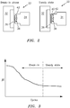
- FIG. 2 illustrates portions of a carbon seal 34 and seal seat 32, including surfaces 36, 38.
- carbon seal 34 is positioned adjacent to an untreated seal seat 36, and initial operation of this seal assembly results in a break-in phase wherein a coefficient of friction between the surfaces, as shown in FIG. 3 , starts relatively high and gradually decreases.
- the image shown in the right hand portion of FIG. 2 shows seal assembly 22 after the break-in phase.
- a thin transfer film 40 has been transferred from carbon seal 34 to sealing surface 36 of seal seat 32. Once this film 40 is transferred to surface 36, seal assembly 22 operates in steady state conditions for the remainder of life of the seal assembly, and FIG. 3 shows this portion of the operation of seal assembly having a relatively lower coefficient of friction than was present during the break-in phase.
- FIG. 2 shows carbon seal 34 having film controllers 42 which can be provided in carbon seal 34. These film controllers 42 serve to prevent excessive build up of thickness of the transfer film 40, thereby maintaining the desired carbon-carbon sliding surfaces defined by carbon seal 34 on one side and the transfer film 40 on the other.
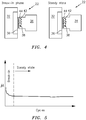
- FIGS. 4 and 5 together show a seal assembly wherein the seal seat is pre-conditioned as disclosed herein.
- seal seat 32 already has been pre-conditioned to have a carbon-based tribofilm 44 on sealing surface 36.
- the coefficient of friction is already low due to the carbon-carbon interaction between the carbon seal and carbon-based tribofilm.
- Steady state operation of this seal assembly results in a transfer film of carbon material being positioned over the carbon-based tribofilm, at least to some extent, and this steady state operation leads to extended useful life of the relevant components. This is shown in FIG.
- Carbon seal 34 can be provided of a suitable electrocarbon such as FT2650, which is an electrographitic grade carbon.
- the seal seat can typically be provided from a wide variety of different materials, including but not limited to structures having a chromium carbide coated counterface or seal seat.
- Film 44 can be deposited by mounting a seal seat 32 in a rig or other suitable apparatus such that a carbon-based member or body can be positioned against surface 36 of seal seat 32 and the surface is pre-conditioned or pre-filmed with a carbon-based tribofilm.
- the transfer film or tribofilm should be graphitic in nature (i.e. high sp2 content) with basel planes parallel to the sliding direction.
- the carbon-based member can comprise a material selected from the group consisting of electro-graphite, carbon-graphite and mixtures thereof. Further, the carbon-based member can itself be a seal member, but it would of course be a different seal member than the seal ultimately to be deployed opposite the seal seat in a gas turbine engine.
- the rig can suitably be operated to apply carbon to the seal seat at a pressure*velocity (PV) of between 1300 and 7000 psi*ft/sec (between 2.73 MPa*m and 14.7 MPa*m) for a period of at least 1 minute, more suitably at least 3 minutes.
- PV pressure*velocity
- the rig can suitably be operated to apply a transfer film or tribofilm to the seal seat having a thickness of between 2 and 240 nm, more suitably between 20 and 200 nm, and still further more suitably between 50 and 140 nm.
- the main characterization method for the transfer film is micro-Raman.
- Micro-Raman provides a 'G' and a 'D' peak values that are indicative of good film properties.
- the transfer film can have a hardness which is similar to that of the seal.
- the transfer or tribofilm can have hardness values between 0.7 and 1.8 GPa (measured by nano-indentation).
- seal 26, 34 can be mounted in a gas turbine engine by being fixed to any suitable structure or seal carrier such as structure 12, 18. Further, seal seat 24, 32 can suitably be mounted to rotational member 10 such that sealing surfaces 28, 30, and 36, 38, respectively, are in close sliding proximity to each other when rotational element 10 is rotated.
- FIGS. 4 and 5 are presented with respect to a rear seal assembly. Illustrations of the same components for a front seal assembly are not provided herein, as the structures would be the same but for being reversed left-to-right.
- a DLC thin film 44 ( FIG. 4 ) in accordance with the present disclosure produces a low friction and wear-resistant carbon-based seal interface which, for example, can operate effectively between 200°F and 350°F (between 93°C and 177°C), under elevated sliding velocities. This, in turn, can reduce sub-surface heating (for example due to frictional heating) by reducing the friction coefficient and improving the break-in phase, which will consequently improve long-term wear resistance of the seal system.
- Pre-filming of the seal seat with a carbon-based tribofilm as referred to above creates a carbon-carbon interface with low friction from the beginning of operation, and therefore produces a very short break-in phase.
- a transfer film is still formed on the seal seat, specifically over the tribofilm, and this configuration remains through steady state operation of the seal.
- seal assembly as disclosed herein can be useful, for example in bearing seals in gas turbine engines, and in other locations as well, and can significantly increase the endurance life of engine components. Further, utilization of seal assemblies as disclosed herein can significantly reduce overall costs by reducing the number of parts that are stripped prematurely due to wear and thermal damage issues.
Landscapes
- Engineering & Computer Science (AREA)
- General Engineering & Computer Science (AREA)
- Chemical & Material Sciences (AREA)
- Mechanical Engineering (AREA)
- Organic Chemistry (AREA)
- General Life Sciences & Earth Sciences (AREA)
- Inorganic Chemistry (AREA)
- Geology (AREA)
- Life Sciences & Earth Sciences (AREA)
- Chemical Kinetics & Catalysis (AREA)
- Metallurgy (AREA)
- Materials Engineering (AREA)
- Sealing Devices (AREA)
- Mechanical Sealing (AREA)
- Sealing Material Composition (AREA)
- Turbine Rotor Nozzle Sealing (AREA)
Abstract
Description
- The disclosure relates to a seal assembly, and more particularly to a bearing seal for a gas turbine engine.
- Gas turbine engines have rotating elements mounted within stationary components at bearings which must be sealed to prevent escape of oil. Such seals are known as bearing seals or oil seals. One form of seal for such purpose is a carbon seal, where a carbon material seal is closely positioned around or relative to a rotating element. When first operated, such a seal results in the transfer of carbon from the carbon seal to the rotating element or seat of the seal assembly to form a film of carbon on the seat. This film is intended to have a low coefficient of friction with the seal, such that escape of oil between the seal and seat is prevented while operating at an acceptably low coefficient of friction.
- This period of operation, when the film is formed, is referred to as the break-in phase of the seal. During break-in, excessive friction can be created, resulting in potential excessive wear on parts of the seal, excessive heat at locations of the seal or seat, and other issues. This issue is all the more serious in seals which are to operate at high velocity and relatively low pressure, which can increase the already high temperature due to friction. The present disclosure addresses this issue.
- In accordance with the present disclosure, there is provided a method for preparing a seal assembly for a gas turbine engine, comprising a seal comprising a carbon material; and a seal seat positioned for rotation relative to the seal, wherein the method comprises the steps of: pre-filming a sealing surface of the seal seat with a carbon-based tribofilm; and assembling the seal seat relative to the seal in a gas turbine engine.
- In a further non-limiting embodiment, the pre-filming step comprises mounting the seal seat in a component rig.
- In a still further non-limiting embodiment, the component rig is operated to apply carbon to the seal seat at a pressure*velocity (PV) of between 1300 and 7000 psi*ft/sec for a period of at least 1 minute.
- In another non-limiting embodiment, the carbon-based tribofilm has a thickness of between 2 and 240 nm.
- In still another non-limiting embodiment, the prefilming step comprises contacting the seal seat with a carbon-based member, which can be comprise a material selected from the group consisting of electro-graphite, carbon-graphite and mixtures thereof.
- In another non-limiting embodiment, the method further comprises the step of operating the gas turbine engine after the assembling step whereby a carbon transfer film is applied over the carbon-based tribofilm during steady state operation.
- In a further non-limiting embodiment, a pre-conditioned seal seat has a sealing surface and a carbon-based tribofilm on the sealing surface.
- In a still further non-limiting embodiment, the carbon-based tribofilm has a coefficient of friction with a carbon-based seal of between 0.06 and 0.16.
- In another non-limiting embodiment, the carbon-based tribofilm of the pre-conditioned seal seat has a thickness of between 20 and 200 nm.
- Other details of the method and seal assembly are set forth in the following detailed description and the accompanying drawings wherein like reference numerals depict like elements.
-
-
FIG. 1 illustrates a simplified cross-sectional view of a portion of a gas turbine engine; -
FIG. 2 illustrates a simplified cross-sectional view of a prior art seal assembly for a gas turbine engine; -
FIG. 3 illustrates coefficient of friction for the seal assembly ofFIG. 2 during break-in and then steady state operation; -
FIG. 4 illustrates a simplified cross-sectional view of a seal assembly for a gas turbine engine as disclosed herein; and -
FIG. 5 illustrates coefficient of friction for the seal ofFIG. 4 during break-in and then steady state operation. - The disclosure relates to a seal assembly for a gas turbine engine and, more particularly, to a carbon seal assembly for the oil seals of a gas turbine engine.
-
FIG. 1 is a cross-sectional illustration of a portion of a gas turbine engine, and illustrates typical components of such an engine. Of interest to the present disclosure is arotational shaft 10 to which are coupled various operative components of the engine, andstationary structures structure 10 to perform desired functions. Other features of the engine have been removed from the view ofFIG. 1 , or reduced to simple schematic illustration, to allow focus on features which are pertinent to the present disclosure. - In such a setting,
FIG. 1 illustrates afront seal assembly 20 and arear seal assembly 22, each of which serves to prevent leakage or flow of oil past the seal, and thereby maintain oil where desired and needed in the gas turbine engine, for example in a bearing compartment defined between the twoseal assemblies -
Seal assembly 20 is defined by afront seal seat 24 and acarbon seal 26.Carbon seal 26 remains stationary relative to rotatingelement 10 andseal seat 24. As shown inFIG. 1 , each of these components has asealing surface surfaces seal assembly 22 is defined by arear seal seat 32 and acarbon seal assembly 34, each of which definessealing surfaces -
FIG. 2 illustrates portions of acarbon seal 34 andseal seat 32, includingsurfaces carbon seal 34 is positioned adjacent to anuntreated seal seat 36, and initial operation of this seal assembly results in a break-in phase wherein a coefficient of friction between the surfaces, as shown inFIG. 3 , starts relatively high and gradually decreases. The image shown in the right hand portion ofFIG. 2 showsseal assembly 22 after the break-in phase. At this stage, a thin transfer film 40 has been transferred fromcarbon seal 34 to sealingsurface 36 ofseal seat 32. Once this film 40 is transferred tosurface 36,seal assembly 22 operates in steady state conditions for the remainder of life of the seal assembly, andFIG. 3 shows this portion of the operation of seal assembly having a relatively lower coefficient of friction than was present during the break-in phase. -
FIG. 2 showscarbon seal 34 havingfilm controllers 42 which can be provided incarbon seal 34. Thesefilm controllers 42 serve to prevent excessive build up of thickness of the transfer film 40, thereby maintaining the desired carbon-carbon sliding surfaces defined bycarbon seal 34 on one side and the transfer film 40 on the other. -
FIGS. 4 and 5 together show a seal assembly wherein the seal seat is pre-conditioned as disclosed herein. Thus, in the break-in phase illustrated on the left side of the drawing,seal seat 32 already has been pre-conditioned to have a carbon-basedtribofilm 44 on sealingsurface 36. Thus, when operation begins, the coefficient of friction is already low due to the carbon-carbon interaction between the carbon seal and carbon-based tribofilm. Steady state operation of this seal assembly results in a transfer film of carbon material being positioned over the carbon-based tribofilm, at least to some extent, and this steady state operation leads to extended useful life of the relevant components. This is shown inFIG. 5 , wherein steady state operation begins substantially immediately, without a significant break-in phase, and the coefficient of friction at steady state is relatively low as compared to that shown inFIG. 3 . During operation of a gas turbine engine having a seal assembly as shown inFIG. 4 , a transfer film is still eventually deposited fromcarbon seal 34 over DLCthin film 44, and the thickness of this transfer film is also controlled, for example byfilm controllers 42 which can also be present incarbon seal 34 according to this aspect of the disclosure. -
Carbon seal 34 can be provided of a suitable electrocarbon such as FT2650, which is an electrographitic grade carbon. The seal seat can typically be provided from a wide variety of different materials, including but not limited to structures having a chromium carbide coated counterface or seal seat. -
Film 44 can be deposited by mounting aseal seat 32 in a rig or other suitable apparatus such that a carbon-based member or body can be positioned againstsurface 36 ofseal seat 32 and the surface is pre-conditioned or pre-filmed with a carbon-based tribofilm. The transfer film or tribofilm should be graphitic in nature (i.e. high sp2 content) with basel planes parallel to the sliding direction. - The carbon-based member can comprise a material selected from the group consisting of electro-graphite, carbon-graphite and mixtures thereof. Further, the carbon-based member can itself be a seal member, but it would of course be a different seal member than the seal ultimately to be deployed opposite the seal seat in a gas turbine engine.
- The rig can suitably be operated to apply carbon to the seal seat at a pressure*velocity (PV) of between 1300 and 7000 psi*ft/sec (between 2.73 MPa*m and 14.7 MPa*m) for a period of at least 1 minute, more suitably at least 3 minutes.
- The rig can suitably be operated to apply a transfer film or tribofilm to the seal seat having a thickness of between 2 and 240 nm, more suitably between 20 and 200 nm, and still further more suitably between 50 and 140 nm.
- The main characterization method for the transfer film is micro-Raman. Micro-Raman provides a 'G' and a 'D' peak values that are indicative of good film properties. One measure of a good low friction transfer film is one which has an I(D)/I(G) peak ratio of < or = 1.0 based on micro-Raman analysis.
- In addition, the transfer film can have a hardness which is similar to that of the seal. Thus, the transfer or tribofilm can have hardness values between 0.7 and 1.8 GPa (measured by nano-indentation).
- With reference back to
FIG. 1 , it should be appreciated thatseal structure seat rotational member 10 such that sealing surfaces 28, 30, and 36, 38, respectively, are in close sliding proximity to each other whenrotational element 10 is rotated. - It should be appreciated that the illustrations of
FIGS. 4 and 5 are presented with respect to a rear seal assembly. Illustrations of the same components for a front seal assembly are not provided herein, as the structures would be the same but for being reversed left-to-right. - It should be appreciated that the pre-application of a DLC thin film 44 (
FIG. 4 ) in accordance with the present disclosure produces a low friction and wear-resistant carbon-based seal interface which, for example, can operate effectively between 200°F and 350°F (between 93°C and 177°C), under elevated sliding velocities. This, in turn, can reduce sub-surface heating (for example due to frictional heating) by reducing the friction coefficient and improving the break-in phase, which will consequently improve long-term wear resistance of the seal system. - Pre-filming of the seal seat with a carbon-based tribofilm as referred to above creates a carbon-carbon interface with low friction from the beginning of operation, and therefore produces a very short break-in phase. During initial operation, a transfer film is still formed on the seal seat, specifically over the tribofilm, and this configuration remains through steady state operation of the seal.
- It should be appreciated that the low friction and wear resistance produced by the seal assembly as disclosed herein can be useful, for example in bearing seals in gas turbine engines, and in other locations as well, and can significantly increase the endurance life of engine components. Further, utilization of seal assemblies as disclosed herein can significantly reduce overall costs by reducing the number of parts that are stripped prematurely due to wear and thermal damage issues.
- There has been provided a seal assembly and method wherein the break-in phase is reduced in length and impact on seal components, and wherein steady state performance of the seal assembly is improved as compared to a seal assembly without the initial pre-filming step. While the seal assembly method and article has been described in the context of specific embodiments thereof, other unforeseen alternatives, modifications, and variations may become apparent to those skilled in the art having read the foregoing description. Accordingly, it is intended to embrace those alternatives, modifications, and variations which fall within the broad scope of the appended claims.
Claims (10)
- A method for preparing a seal assembly (20, 22) for a gas turbine engine, comprising a seal (26, 34) comprising a carbon material; and a seal seat (24, 32) positioned for rotation relative to the seal (26, 34), wherein the method comprises the steps of:pre-filming a sealing surface (30, 36) of the seal seat (24, 32) with a carbon-based tribofilm (44); andassembling the seal seat (24, 32) relative to the seal (26, 34) in a gas turbine engine.
- The method of claim 1, wherein the pre-filming step comprises mounting the seal seat (24, 32) in a component rig.
- The method of claim 2, wherein the component rig is operated to apply carbon to the seal seat at a pressure *velocity (PV) of between 1300 psi*ft/sec and 7000 psi*ft/sec (between 2.73 MPa*m/sec and 14.7 MPa*m/sec) for a period of at least 1 minute.
- The method of claim 1, 2 or 3, wherein the carbon-based tribofilm (44) has a thickness of between 2 nm and 240 nm.
- The method of any preceding claim, wherein the prefilming step comprises contacting the seal seat (24, 32) with a carbon-based member.
- The method of claim 5, wherein the carbon-based member comprises a material selected from the group consisting of electro-graphite, carbon-graphite and mixtures thereof.
- The method of any preceding claim, further comprising the step of operating the gas turbine engine after the assembling step whereby a carbon transfer film (40) is applied over the carbon-based tribofilm (44) during steady state operation.
- A pre-conditioned seal seat (24, 32) having a sealing surface (30, 36) and a carbon-based tribofilm (44) on the sealing surface (30, 36).
- The seal seat of claim 8, wherein the carbon-based tribofilm (44) has a coefficient of friction with a carbon-based seal (26, 34) of between 0.06 and 0.16.
- The seal seat of claim 8 or 9, wherein the carbon-based tribofilm (44) has a thickness of between 2 nm and 240 nm.
Applications Claiming Priority (1)
| Application Number | Priority Date | Filing Date | Title |
|---|---|---|---|
| US201862733596P | 2018-09-19 | 2018-09-19 |
Publications (2)
| Publication Number | Publication Date |
|---|---|
| EP3626851A1 true EP3626851A1 (en) | 2020-03-25 |
| EP3626851B1 EP3626851B1 (en) | 2024-05-15 |
Family
ID=67998205
Family Applications (1)
| Application Number | Title | Priority Date | Filing Date |
|---|---|---|---|
| EP19198459.0A Active EP3626851B1 (en) | 2018-09-19 | 2019-09-19 | Low friction, wear resistant dry face carbon seal - seal seat assembly |
Country Status (3)
| Country | Link |
|---|---|
| US (1) | US11193384B2 (en) |
| EP (1) | EP3626851B1 (en) |
| JP (1) | JP7556680B2 (en) |
Families Citing this family (3)
| Publication number | Priority date | Publication date | Assignee | Title |
|---|---|---|---|---|
| US12270303B2 (en) | 2022-05-26 | 2025-04-08 | General Electric Company | Seal assembly for a turbomachine |
| US12060798B2 (en) | 2022-05-27 | 2024-08-13 | General Electric Company | Surface treatment for seal assemblies |
| US12241379B2 (en) | 2022-08-03 | 2025-03-04 | General Electric Company | Cooling system for seal assemblies |
Citations (1)
| Publication number | Priority date | Publication date | Assignee | Title |
|---|---|---|---|---|
| WO2017149263A1 (en) * | 2016-03-03 | 2017-09-08 | Wärtsilä Uk Limited | Rotary seal assembly |
Family Cites Families (8)
| Publication number | Priority date | Publication date | Assignee | Title |
|---|---|---|---|---|
| GB1365287A (en) * | 1970-12-11 | 1974-08-29 | Ici Ltd | Graphite compositions |
| JPH11141690A (en) * | 1997-11-11 | 1999-05-25 | Eagle Ind Co Ltd | Sealing device |
| DE10135477A1 (en) | 2001-07-18 | 2003-02-06 | Tea Gmbh | Sliding pairing with a sliding element made on the basis of carbon |
| US7837199B2 (en) | 2005-11-03 | 2010-11-23 | United Technologies Corporation | Shrouded face seal and components thereof |
| US7985703B2 (en) * | 2006-03-15 | 2011-07-26 | United Technologies Corporation | Wear-resistant coating |
| US7754350B2 (en) * | 2006-05-02 | 2010-07-13 | United Technologies Corporation | Wear-resistant coating |
| US9726031B2 (en) * | 2012-09-28 | 2017-08-08 | United Technologies Corporation | Piston ring coated carbon seal |
| CN107532723B (en) * | 2015-04-16 | 2019-11-22 | 伊格尔工业股份有限公司 | sliding parts |
-
2019
- 2019-09-18 US US16/574,589 patent/US11193384B2/en active Active
- 2019-09-19 EP EP19198459.0A patent/EP3626851B1/en active Active
- 2019-09-19 JP JP2019170047A patent/JP7556680B2/en active Active
Patent Citations (1)
| Publication number | Priority date | Publication date | Assignee | Title |
|---|---|---|---|---|
| WO2017149263A1 (en) * | 2016-03-03 | 2017-09-08 | Wärtsilä Uk Limited | Rotary seal assembly |
Also Published As
| Publication number | Publication date |
|---|---|
| US11193384B2 (en) | 2021-12-07 |
| JP2020045901A (en) | 2020-03-26 |
| US20200088055A1 (en) | 2020-03-19 |
| JP7556680B2 (en) | 2024-09-26 |
| EP3626851B1 (en) | 2024-05-15 |
Similar Documents
| Publication | Publication Date | Title |
|---|---|---|
| EP3626851B1 (en) | Low friction, wear resistant dry face carbon seal - seal seat assembly | |
| CN103097574B (en) | Sealing rings with improved running-in properties | |
| Irissou et al. | Tribological characterization of plasma-sprayed CoNiCrAlY-BN abradable coatings | |
| US11560808B2 (en) | Seal assembly for gas turbine engine | |
| US20230323951A1 (en) | Carbon seal assembly | |
| US7985703B2 (en) | Wear-resistant coating | |
| Bill et al. | Friction and wear of sintered fibermetal abradable seal materials | |
| US11739842B2 (en) | High pressure compressor seal-ring with improved wear resistance | |
| EP3865672B1 (en) | Carbon seal assembly | |
| Papatheodorou et al. | Influence of hard chrome plated rod surface treatments on sealing behavior of hydraulic rod seals | |
| Balyakin et al. | Methods and means of reducing friction torque in face seals | |
| Ross et al. | Tribological Characteristics of Manufactured Carbon Under Extreme Contact Conditions. | |
| US11719114B2 (en) | Low friction carbon—carbon seal assembly | |
| US20230323782A1 (en) | Carbon seal assembly | |
| CN110062861B (en) | Friction plate, mechanical system comprising such a friction plate and method of implementation | |
| JP3281253B2 (en) | Gas seal | |
| KR20190068149A (en) | Carbon mechanical seal with DLC thin film | |
| JPH11141690A (en) | Sealing device | |
| WO2022209965A1 (en) | Sliding component | |
| Haas et al. | Wear Resistant Coatings for Radial Shaft Sealing Systems | |
| Heck | The circumferential seal: its application, its place in the seal spectrum relative to gas turbines | |
| Suzuki et al. | Transfer Film Lubrication for Ceramic Pairs at a Temperature of 800° C and a Pressure of 1300 Pa | |
| Miller et al. | The Selection and Testing of Compression Seal and Chamber Coating Materials for the Pivotal™ Engine | |
| DellaCorte | Solid Lubricants for Oil-Free Turbomachinery |
Legal Events
| Date | Code | Title | Description |
|---|---|---|---|
| PUAI | Public reference made under article 153(3) epc to a published international application that has entered the european phase |
Free format text: ORIGINAL CODE: 0009012 |
|
| STAA | Information on the status of an ep patent application or granted ep patent |
Free format text: STATUS: THE APPLICATION HAS BEEN PUBLISHED |
|
| AK | Designated contracting states |
Kind code of ref document: A1 Designated state(s): AL AT BE BG CH CY CZ DE DK EE ES FI FR GB GR HR HU IE IS IT LI LT LU LV MC MK MT NL NO PL PT RO RS SE SI SK SM TR |
|
| AX | Request for extension of the european patent |
Extension state: BA ME |
|
| STAA | Information on the status of an ep patent application or granted ep patent |
Free format text: STATUS: REQUEST FOR EXAMINATION WAS MADE |
|
| 17P | Request for examination filed |
Effective date: 20200924 |
|
| RBV | Designated contracting states (corrected) |
Designated state(s): AL AT BE BG CH CY CZ DE DK EE ES FI FR GB GR HR HU IE IS IT LI LT LU LV MC MK MT NL NO PL PT RO RS SE SI SK SM TR |
|
| RAP1 | Party data changed (applicant data changed or rights of an application transferred) |
Owner name: RAYTHEON TECHNOLOGIES CORPORATION |
|
| STAA | Information on the status of an ep patent application or granted ep patent |
Free format text: STATUS: EXAMINATION IS IN PROGRESS |
|
| 17Q | First examination report despatched |
Effective date: 20210806 |
|
| RAP3 | Party data changed (applicant data changed or rights of an application transferred) |
Owner name: RTX CORPORATION |
|
| REG | Reference to a national code |
Ref country code: DE Ref legal event code: R079 Free format text: PREVIOUS MAIN CLASS: C23C0014020000 Ipc: C23C0024020000 Ref document number: 602019052182 Country of ref document: DE |
|
| GRAP | Despatch of communication of intention to grant a patent |
Free format text: ORIGINAL CODE: EPIDOSNIGR1 |
|
| STAA | Information on the status of an ep patent application or granted ep patent |
Free format text: STATUS: GRANT OF PATENT IS INTENDED |
|
| RIC1 | Information provided on ipc code assigned before grant |
Ipc: F16J 15/34 20060101ALI20231128BHEP Ipc: F01D 25/18 20060101ALI20231128BHEP Ipc: C23C 24/02 20060101AFI20231128BHEP |
|
| INTG | Intention to grant announced |
Effective date: 20231214 |
|
| GRAS | Grant fee paid |
Free format text: ORIGINAL CODE: EPIDOSNIGR3 |
|
| GRAA | (expected) grant |
Free format text: ORIGINAL CODE: 0009210 |
|
| STAA | Information on the status of an ep patent application or granted ep patent |
Free format text: STATUS: THE PATENT HAS BEEN GRANTED |
|
| AK | Designated contracting states |
Kind code of ref document: B1 Designated state(s): AL AT BE BG CH CY CZ DE DK EE ES FI FR GB GR HR HU IE IS IT LI LT LU LV MC MK MT NL NO PL PT RO RS SE SI SK SM TR |
|
| REG | Reference to a national code |
Ref country code: CH Ref legal event code: EP |
|
| REG | Reference to a national code |
Ref country code: DE Ref legal event code: R096 Ref document number: 602019052182 Country of ref document: DE |
|
| REG | Reference to a national code |
Ref country code: IE Ref legal event code: FG4D |
|
| REG | Reference to a national code |
Ref country code: LT Ref legal event code: MG9D |
|
| REG | Reference to a national code |
Ref country code: NL Ref legal event code: MP Effective date: 20240515 |
|
| PG25 | Lapsed in a contracting state [announced via postgrant information from national office to epo] |
Ref country code: IS Free format text: LAPSE BECAUSE OF FAILURE TO SUBMIT A TRANSLATION OF THE DESCRIPTION OR TO PAY THE FEE WITHIN THE PRESCRIBED TIME-LIMIT Effective date: 20240915 |
|
| PG25 | Lapsed in a contracting state [announced via postgrant information from national office to epo] |
Ref country code: BG Free format text: LAPSE BECAUSE OF FAILURE TO SUBMIT A TRANSLATION OF THE DESCRIPTION OR TO PAY THE FEE WITHIN THE PRESCRIBED TIME-LIMIT Effective date: 20240515 |
|
| PG25 | Lapsed in a contracting state [announced via postgrant information from national office to epo] |
Ref country code: FI Free format text: LAPSE BECAUSE OF FAILURE TO SUBMIT A TRANSLATION OF THE DESCRIPTION OR TO PAY THE FEE WITHIN THE PRESCRIBED TIME-LIMIT Effective date: 20240515 Ref country code: HR Free format text: LAPSE BECAUSE OF FAILURE TO SUBMIT A TRANSLATION OF THE DESCRIPTION OR TO PAY THE FEE WITHIN THE PRESCRIBED TIME-LIMIT Effective date: 20240515 |
|
| PG25 | Lapsed in a contracting state [announced via postgrant information from national office to epo] |
Ref country code: GR Free format text: LAPSE BECAUSE OF FAILURE TO SUBMIT A TRANSLATION OF THE DESCRIPTION OR TO PAY THE FEE WITHIN THE PRESCRIBED TIME-LIMIT Effective date: 20240816 |
|
| PG25 | Lapsed in a contracting state [announced via postgrant information from national office to epo] |
Ref country code: PT Free format text: LAPSE BECAUSE OF FAILURE TO SUBMIT A TRANSLATION OF THE DESCRIPTION OR TO PAY THE FEE WITHIN THE PRESCRIBED TIME-LIMIT Effective date: 20240916 |
|
| REG | Reference to a national code |
Ref country code: AT Ref legal event code: MK05 Ref document number: 1686952 Country of ref document: AT Kind code of ref document: T Effective date: 20240515 |
|
| PG25 | Lapsed in a contracting state [announced via postgrant information from national office to epo] |
Ref country code: NL Free format text: LAPSE BECAUSE OF FAILURE TO SUBMIT A TRANSLATION OF THE DESCRIPTION OR TO PAY THE FEE WITHIN THE PRESCRIBED TIME-LIMIT Effective date: 20240515 |
|
| PG25 | Lapsed in a contracting state [announced via postgrant information from national office to epo] |
Ref country code: ES Free format text: LAPSE BECAUSE OF FAILURE TO SUBMIT A TRANSLATION OF THE DESCRIPTION OR TO PAY THE FEE WITHIN THE PRESCRIBED TIME-LIMIT Effective date: 20240515 |
|
| PG25 | Lapsed in a contracting state [announced via postgrant information from national office to epo] |
Ref country code: AT Free format text: LAPSE BECAUSE OF FAILURE TO SUBMIT A TRANSLATION OF THE DESCRIPTION OR TO PAY THE FEE WITHIN THE PRESCRIBED TIME-LIMIT Effective date: 20240515 |
|
| PG25 | Lapsed in a contracting state [announced via postgrant information from national office to epo] |
Ref country code: PL Free format text: LAPSE BECAUSE OF FAILURE TO SUBMIT A TRANSLATION OF THE DESCRIPTION OR TO PAY THE FEE WITHIN THE PRESCRIBED TIME-LIMIT Effective date: 20240515 |
|
| PG25 | Lapsed in a contracting state [announced via postgrant information from national office to epo] |
Ref country code: LV Free format text: LAPSE BECAUSE OF FAILURE TO SUBMIT A TRANSLATION OF THE DESCRIPTION OR TO PAY THE FEE WITHIN THE PRESCRIBED TIME-LIMIT Effective date: 20240515 |
|
| PG25 | Lapsed in a contracting state [announced via postgrant information from national office to epo] |
Ref country code: PT Free format text: LAPSE BECAUSE OF FAILURE TO SUBMIT A TRANSLATION OF THE DESCRIPTION OR TO PAY THE FEE WITHIN THE PRESCRIBED TIME-LIMIT Effective date: 20240916 Ref country code: PL Free format text: LAPSE BECAUSE OF FAILURE TO SUBMIT A TRANSLATION OF THE DESCRIPTION OR TO PAY THE FEE WITHIN THE PRESCRIBED TIME-LIMIT Effective date: 20240515 Ref country code: NO Free format text: LAPSE BECAUSE OF FAILURE TO SUBMIT A TRANSLATION OF THE DESCRIPTION OR TO PAY THE FEE WITHIN THE PRESCRIBED TIME-LIMIT Effective date: 20240815 Ref country code: NL Free format text: LAPSE BECAUSE OF FAILURE TO SUBMIT A TRANSLATION OF THE DESCRIPTION OR TO PAY THE FEE WITHIN THE PRESCRIBED TIME-LIMIT Effective date: 20240515 Ref country code: LV Free format text: LAPSE BECAUSE OF FAILURE TO SUBMIT A TRANSLATION OF THE DESCRIPTION OR TO PAY THE FEE WITHIN THE PRESCRIBED TIME-LIMIT Effective date: 20240515 Ref country code: IS Free format text: LAPSE BECAUSE OF FAILURE TO SUBMIT A TRANSLATION OF THE DESCRIPTION OR TO PAY THE FEE WITHIN THE PRESCRIBED TIME-LIMIT Effective date: 20240915 Ref country code: HR Free format text: LAPSE BECAUSE OF FAILURE TO SUBMIT A TRANSLATION OF THE DESCRIPTION OR TO PAY THE FEE WITHIN THE PRESCRIBED TIME-LIMIT Effective date: 20240515 Ref country code: GR Free format text: LAPSE BECAUSE OF FAILURE TO SUBMIT A TRANSLATION OF THE DESCRIPTION OR TO PAY THE FEE WITHIN THE PRESCRIBED TIME-LIMIT Effective date: 20240816 Ref country code: FI Free format text: LAPSE BECAUSE OF FAILURE TO SUBMIT A TRANSLATION OF THE DESCRIPTION OR TO PAY THE FEE WITHIN THE PRESCRIBED TIME-LIMIT Effective date: 20240515 Ref country code: ES Free format text: LAPSE BECAUSE OF FAILURE TO SUBMIT A TRANSLATION OF THE DESCRIPTION OR TO PAY THE FEE WITHIN THE PRESCRIBED TIME-LIMIT Effective date: 20240515 Ref country code: BG Free format text: LAPSE BECAUSE OF FAILURE TO SUBMIT A TRANSLATION OF THE DESCRIPTION OR TO PAY THE FEE WITHIN THE PRESCRIBED TIME-LIMIT Effective date: 20240515 Ref country code: AT Free format text: LAPSE BECAUSE OF FAILURE TO SUBMIT A TRANSLATION OF THE DESCRIPTION OR TO PAY THE FEE WITHIN THE PRESCRIBED TIME-LIMIT Effective date: 20240515 Ref country code: RS Free format text: LAPSE BECAUSE OF FAILURE TO SUBMIT A TRANSLATION OF THE DESCRIPTION OR TO PAY THE FEE WITHIN THE PRESCRIBED TIME-LIMIT Effective date: 20240815 |
|
| PG25 | Lapsed in a contracting state [announced via postgrant information from national office to epo] |
Ref country code: DK Free format text: LAPSE BECAUSE OF FAILURE TO SUBMIT A TRANSLATION OF THE DESCRIPTION OR TO PAY THE FEE WITHIN THE PRESCRIBED TIME-LIMIT Effective date: 20240515 |
|
| PG25 | Lapsed in a contracting state [announced via postgrant information from national office to epo] |
Ref country code: EE Free format text: LAPSE BECAUSE OF FAILURE TO SUBMIT A TRANSLATION OF THE DESCRIPTION OR TO PAY THE FEE WITHIN THE PRESCRIBED TIME-LIMIT Effective date: 20240515 |
|
| PG25 | Lapsed in a contracting state [announced via postgrant information from national office to epo] |
Ref country code: CZ Free format text: LAPSE BECAUSE OF FAILURE TO SUBMIT A TRANSLATION OF THE DESCRIPTION OR TO PAY THE FEE WITHIN THE PRESCRIBED TIME-LIMIT Effective date: 20240515 |
|
| PG25 | Lapsed in a contracting state [announced via postgrant information from national office to epo] |
Ref country code: SK Free format text: LAPSE BECAUSE OF FAILURE TO SUBMIT A TRANSLATION OF THE DESCRIPTION OR TO PAY THE FEE WITHIN THE PRESCRIBED TIME-LIMIT Effective date: 20240515 Ref country code: RO Free format text: LAPSE BECAUSE OF FAILURE TO SUBMIT A TRANSLATION OF THE DESCRIPTION OR TO PAY THE FEE WITHIN THE PRESCRIBED TIME-LIMIT Effective date: 20240515 |
|
| PG25 | Lapsed in a contracting state [announced via postgrant information from national office to epo] |
Ref country code: SM Free format text: LAPSE BECAUSE OF FAILURE TO SUBMIT A TRANSLATION OF THE DESCRIPTION OR TO PAY THE FEE WITHIN THE PRESCRIBED TIME-LIMIT Effective date: 20240515 |
|
| PG25 | Lapsed in a contracting state [announced via postgrant information from national office to epo] |
Ref country code: SM Free format text: LAPSE BECAUSE OF FAILURE TO SUBMIT A TRANSLATION OF THE DESCRIPTION OR TO PAY THE FEE WITHIN THE PRESCRIBED TIME-LIMIT Effective date: 20240515 Ref country code: SK Free format text: LAPSE BECAUSE OF FAILURE TO SUBMIT A TRANSLATION OF THE DESCRIPTION OR TO PAY THE FEE WITHIN THE PRESCRIBED TIME-LIMIT Effective date: 20240515 Ref country code: RO Free format text: LAPSE BECAUSE OF FAILURE TO SUBMIT A TRANSLATION OF THE DESCRIPTION OR TO PAY THE FEE WITHIN THE PRESCRIBED TIME-LIMIT Effective date: 20240515 Ref country code: EE Free format text: LAPSE BECAUSE OF FAILURE TO SUBMIT A TRANSLATION OF THE DESCRIPTION OR TO PAY THE FEE WITHIN THE PRESCRIBED TIME-LIMIT Effective date: 20240515 Ref country code: DK Free format text: LAPSE BECAUSE OF FAILURE TO SUBMIT A TRANSLATION OF THE DESCRIPTION OR TO PAY THE FEE WITHIN THE PRESCRIBED TIME-LIMIT Effective date: 20240515 Ref country code: CZ Free format text: LAPSE BECAUSE OF FAILURE TO SUBMIT A TRANSLATION OF THE DESCRIPTION OR TO PAY THE FEE WITHIN THE PRESCRIBED TIME-LIMIT Effective date: 20240515 |
|
| PG25 | Lapsed in a contracting state [announced via postgrant information from national office to epo] |
Ref country code: IT Free format text: LAPSE BECAUSE OF FAILURE TO SUBMIT A TRANSLATION OF THE DESCRIPTION OR TO PAY THE FEE WITHIN THE PRESCRIBED TIME-LIMIT Effective date: 20240515 |
|
| REG | Reference to a national code |
Ref country code: DE Ref legal event code: R097 Ref document number: 602019052182 Country of ref document: DE |
|
| PLBE | No opposition filed within time limit |
Free format text: ORIGINAL CODE: 0009261 |
|
| STAA | Information on the status of an ep patent application or granted ep patent |
Free format text: STATUS: NO OPPOSITION FILED WITHIN TIME LIMIT |
|
| 26N | No opposition filed |
Effective date: 20250218 |
|
| PG25 | Lapsed in a contracting state [announced via postgrant information from national office to epo] |
Ref country code: SI Free format text: LAPSE BECAUSE OF FAILURE TO SUBMIT A TRANSLATION OF THE DESCRIPTION OR TO PAY THE FEE WITHIN THE PRESCRIBED TIME-LIMIT Effective date: 20240515 Ref country code: MC Free format text: LAPSE BECAUSE OF FAILURE TO SUBMIT A TRANSLATION OF THE DESCRIPTION OR TO PAY THE FEE WITHIN THE PRESCRIBED TIME-LIMIT Effective date: 20240515 |
|
| REG | Reference to a national code |
Ref country code: CH Ref legal event code: PL |
|
| PG25 | Lapsed in a contracting state [announced via postgrant information from national office to epo] |
Ref country code: LU Free format text: LAPSE BECAUSE OF NON-PAYMENT OF DUE FEES Effective date: 20240919 |
|
| REG | Reference to a national code |
Ref country code: BE Ref legal event code: MM Effective date: 20240930 |
|
| PG25 | Lapsed in a contracting state [announced via postgrant information from national office to epo] |
Ref country code: BE Free format text: LAPSE BECAUSE OF NON-PAYMENT OF DUE FEES Effective date: 20240930 |
|
| PG25 | Lapsed in a contracting state [announced via postgrant information from national office to epo] |
Ref country code: CH Free format text: LAPSE BECAUSE OF NON-PAYMENT OF DUE FEES Effective date: 20240930 |
|
| PG25 | Lapsed in a contracting state [announced via postgrant information from national office to epo] |
Ref country code: IE Free format text: LAPSE BECAUSE OF NON-PAYMENT OF DUE FEES Effective date: 20240919 |
|
| PG25 | Lapsed in a contracting state [announced via postgrant information from national office to epo] |
Ref country code: SE Free format text: LAPSE BECAUSE OF FAILURE TO SUBMIT A TRANSLATION OF THE DESCRIPTION OR TO PAY THE FEE WITHIN THE PRESCRIBED TIME-LIMIT Effective date: 20240515 |
|
| PGFP | Annual fee paid to national office [announced via postgrant information from national office to epo] |
Ref country code: DE Payment date: 20250820 Year of fee payment: 7 |
|
| PGFP | Annual fee paid to national office [announced via postgrant information from national office to epo] |
Ref country code: GB Payment date: 20250820 Year of fee payment: 7 |
|
| PGFP | Annual fee paid to national office [announced via postgrant information from national office to epo] |
Ref country code: FR Payment date: 20250821 Year of fee payment: 7 |
|
| PG25 | Lapsed in a contracting state [announced via postgrant information from national office to epo] |
Ref country code: CY Free format text: LAPSE BECAUSE OF FAILURE TO SUBMIT A TRANSLATION OF THE DESCRIPTION OR TO PAY THE FEE WITHIN THE PRESCRIBED TIME-LIMIT; INVALID AB INITIO Effective date: 20190919 |
|
| PG25 | Lapsed in a contracting state [announced via postgrant information from national office to epo] |
Ref country code: HU Free format text: LAPSE BECAUSE OF FAILURE TO SUBMIT A TRANSLATION OF THE DESCRIPTION OR TO PAY THE FEE WITHIN THE PRESCRIBED TIME-LIMIT; INVALID AB INITIO Effective date: 20190919 |