EP3626810A1 - Foam breaker for fermentation tank and microorganism fermentation tank using foam breaker for fermentation tank - Google Patents
Foam breaker for fermentation tank and microorganism fermentation tank using foam breaker for fermentation tank Download PDFInfo
- Publication number
- EP3626810A1 EP3626810A1 EP18802811.2A EP18802811A EP3626810A1 EP 3626810 A1 EP3626810 A1 EP 3626810A1 EP 18802811 A EP18802811 A EP 18802811A EP 3626810 A1 EP3626810 A1 EP 3626810A1
- Authority
- EP
- European Patent Office
- Prior art keywords
- fermenter
- defoamer
- veins
- microorganism
- foams
- Prior art date
- Legal status (The legal status is an assumption and is not a legal conclusion. Google has not performed a legal analysis and makes no representation as to the accuracy of the status listed.)
- Pending
Links
- 244000005700 microbiome Species 0.000 title claims description 31
- 238000000855 fermentation Methods 0.000 title claims description 26
- 230000004151 fermentation Effects 0.000 title claims description 26
- 239000006260 foam Substances 0.000 title description 47
- 239000013530 defoamer Substances 0.000 claims abstract description 79
- 210000003462 vein Anatomy 0.000 claims abstract description 72
- 238000000034 method Methods 0.000 claims description 12
- 238000013019 agitation Methods 0.000 claims description 9
- 239000013077 target material Substances 0.000 claims description 6
- 238000004519 manufacturing process Methods 0.000 claims description 5
- 230000008878 coupling Effects 0.000 claims description 3
- 238000010168 coupling process Methods 0.000 claims description 3
- 238000005859 coupling reaction Methods 0.000 claims description 3
- 238000000926 separation method Methods 0.000 claims description 3
- 239000003795 chemical substances by application Substances 0.000 description 6
- 230000000694 effects Effects 0.000 description 6
- 239000001963 growth medium Substances 0.000 description 6
- 238000002474 experimental method Methods 0.000 description 4
- 239000012530 fluid Substances 0.000 description 4
- 239000007788 liquid Substances 0.000 description 4
- 238000011109 contamination Methods 0.000 description 3
- 230000008021 deposition Effects 0.000 description 3
- 238000013461 design Methods 0.000 description 2
- 238000012795 verification Methods 0.000 description 2
- KDXKERNSBIXSRK-UHFFFAOYSA-N Lysine Natural products NCCCCC(N)C(O)=O KDXKERNSBIXSRK-UHFFFAOYSA-N 0.000 description 1
- 239000004472 Lysine Substances 0.000 description 1
- 235000013334 alcoholic beverage Nutrition 0.000 description 1
- QVGXLLKOCUKJST-UHFFFAOYSA-N atomic oxygen Chemical compound [O] QVGXLLKOCUKJST-UHFFFAOYSA-N 0.000 description 1
- 235000013405 beer Nutrition 0.000 description 1
- 238000005452 bending Methods 0.000 description 1
- 238000005842 biochemical reaction Methods 0.000 description 1
- 150000001720 carbohydrates Chemical class 0.000 description 1
- UBAZGMLMVVQSCD-UHFFFAOYSA-N carbon dioxide;molecular oxygen Chemical compound O=O.O=C=O UBAZGMLMVVQSCD-UHFFFAOYSA-N 0.000 description 1
- 235000021001 fermented dairy product Nutrition 0.000 description 1
- 238000007667 floating Methods 0.000 description 1
- 235000013305 food Nutrition 0.000 description 1
- 238000009434 installation Methods 0.000 description 1
- 238000012986 modification Methods 0.000 description 1
- 230000004048 modification Effects 0.000 description 1
- 229910052760 oxygen Inorganic materials 0.000 description 1
- 239000001301 oxygen Substances 0.000 description 1
- 230000002093 peripheral effect Effects 0.000 description 1
- 235000019992 sake Nutrition 0.000 description 1
- 235000019997 soju Nutrition 0.000 description 1
- 235000015041 whisky Nutrition 0.000 description 1
- 235000014101 wine Nutrition 0.000 description 1
Images






Classifications
-
- C—CHEMISTRY; METALLURGY
- C12—BIOCHEMISTRY; BEER; SPIRITS; WINE; VINEGAR; MICROBIOLOGY; ENZYMOLOGY; MUTATION OR GENETIC ENGINEERING
- C12M—APPARATUS FOR ENZYMOLOGY OR MICROBIOLOGY; APPARATUS FOR CULTURING MICROORGANISMS FOR PRODUCING BIOMASS, FOR GROWING CELLS OR FOR OBTAINING FERMENTATION OR METABOLIC PRODUCTS, i.e. BIOREACTORS OR FERMENTERS
- C12M41/00—Means for regulation, monitoring, measurement or control, e.g. flow regulation
- C12M41/02—Means for regulation, monitoring, measurement or control, e.g. flow regulation of foam
-
- B—PERFORMING OPERATIONS; TRANSPORTING
- B01—PHYSICAL OR CHEMICAL PROCESSES OR APPARATUS IN GENERAL
- B01D—SEPARATION
- B01D19/00—Degasification of liquids
- B01D19/0042—Degasification of liquids modifying the liquid flow
- B01D19/0052—Degasification of liquids modifying the liquid flow in rotating vessels, vessels containing movable parts or in which centrifugal movement is caused
-
- C—CHEMISTRY; METALLURGY
- C12—BIOCHEMISTRY; BEER; SPIRITS; WINE; VINEGAR; MICROBIOLOGY; ENZYMOLOGY; MUTATION OR GENETIC ENGINEERING
- C12M—APPARATUS FOR ENZYMOLOGY OR MICROBIOLOGY; APPARATUS FOR CULTURING MICROORGANISMS FOR PRODUCING BIOMASS, FOR GROWING CELLS OR FOR OBTAINING FERMENTATION OR METABOLIC PRODUCTS, i.e. BIOREACTORS OR FERMENTERS
- C12M27/00—Means for mixing, agitating or circulating fluids in the vessel
- C12M27/02—Stirrer or mobile mixing elements
Definitions
- the present invention relates to a defoamer used for a fermenter and a fermenter using the defoamer, and more particularly to a defoamer which can effectively remove foams produced in a fermenter, and a fermenter.
- foams are formed in fermentation culture media due to introduced oxygen, carbon dioxide produced by fermentation of microorganisms, and the like.
- a foam reduction agent for suppressing production of foams in the fermenter may be introduced, but when the foam reduction agent is excessively introduced, a problem may be caused in the quality of the product.
- the disk defoamer is installed in a shaft of an agitator in the interior of a fermenter to remove surrounding foams by using a centrifugal force generated through rotation of the shaft, and has a different effect according to the form of the defoamer.
- U.S. Patent No. 6673599 discloses a disk defoamer used for a fermenter, but defoaming efficiency deteriorates due to a small effective defoaming area, defoaming capacity significantly deteriorates when the height of the foams of broth is higher than the height of the defoamer, and and the weight of the defoamer is heavy and the structure of the defoamer is very complex so that the defoamer is not suitable for a large-scale fermenter due to a danger of contamination and danger of damage.
- An object of the present invention is to provide a defoamer for a fermenter including: a body 100 having a first hollow 110 at a central portion thereof and having a disk shape; a support 200 having a second hollow 210 connected with the first hollow 110, and extending from an upper surface 120 and a lower surface 130 of the body 100; and a plurality of first veins 310, 320, 330, 340, 350, 360, 370, and 380 mounted on the lower surface 130 of the body 100.
- Another object of the present invention is to provide a microorganism fermenter including the defoamer for a fermenter further including: a container in which a fermentation target material is accommodated; a rotary shaft located at a central portion of the container; and one or more agitation blades mounted on the rotary shaft to be rotatable, wherein the body of the defoamer for a fermenter is mounted on the rotary shaft to be located at a height that is not less than the height of the one or more agitation blades located in the container.
- Another object of the present invention is to provide a microorganism cultivating method using the microorganism fermenter.
- Another object of the present invention is to provide a method for manufacturing a fermentation target object through the microorganism cultivating method.
- An aspect of the present invention provides a defoamer for a fermenter including: a body 100 having a first hollow 110 at a central portion thereof and having a disk shape; a support 200 having a second hollow 210 connected with the first hollow 110, and extending from an upper surface 120 and a lower surface 130 of the body 100; and a plurality of first veins 310, 320, 330, 340, 350, 360, 370, and 380 mounted on the lower surface 130 of the body 100.
- the plurality of first veins 310, 320, 330, 340, 350, 360, 370, and 380 may be mounted on the body 100 while being spaced apart from the support 200 by a predetermined interval.
- foams can be discharged to the outside when the amount of the foams increases abruptly, and the flow of broth (cultivation liquid) (b) can be stabilized.
- any one of the plurality of first veins 310, 320, 330, 340, 350, 360, 370, and 380 may be mounted to the body 100 while being spaced apart from another adjacent first vein at a uniform interval. Through the structure, the defoaming flow that removes foams may be uniformly generated.
- the number of the plurality of first veins 310, 320, 330, 340, 350, 360, 370, and 380 may be eight. However, the number of the plurality of first veins 310, 320, 330, 340, 350, 360, 370, and 380 is not limited to eight, and may be any arbitrary number.
- the first veins 310, 320, 330, 340, 350, 360, 370, and 380 may be formed in a radial direction of the body 100, and each may include an upper end part having a first curvature, which is a curvature that is perpendicular to the body 100, and having a predetermined height, and a lower end part connected to the upper end part, and extending while having a second curvature, which is different from the first curvature.
- the first curvature that is perpendicular to the body 100 may be a curvature that forms 90 degrees with the body 100, but it is noted that the angle is not limited to 90 degrees.
- the inner side of the plurality of first veins 310, 320, 330, 340, 350, 360, 370, and 380 also may be welded when the plurality of first veins 310, 320, 330, 340, 350, 360, 370, and 380 are welded to the body 100 through the structure, the entire circumference of the body 100 may be welded so that contamination due to deposition and residue of broth (b) can be minimized by improving strength and forming a waterproof structure. Since the area in contact with the broth (b) can be increased by the shapes of the plurality of first veins 310, 320, 330, 340, 350, 360, 370, and 380 including the lower ends of the curved structures, foam removal efficiency can be improved.
- the plurality of first veins 310, 320, 330, 340, 350, 360, 370, and 380 may be mounted on the body 100 while being eccentric from a radial direction, of which the center of rotation is the central portion of the body 100, by a predetermined angle ( ⁇ ).
- the direction of eccentricity of the first veins may be the rotational direction of the defoamer, and the predetermined angle ( ⁇ ) may be 10 to 45 degrees, in detail, 13 to 20 degrees.
- the plurality of first veins are mounted on the body 100 after being made eccentric by a predetermined angle ( ⁇ ) so that the predetermined angle ( ⁇ ) is formed to direct the fluid resistance occurred at a contact part to the outside while defoaming the foams, and, thereby minimizes defoaming resistance and stabilizes the flow of the fluid.
- ⁇ predetermined angle
- a plurality of second veins 410, 420, 430, and 440 mounted on the upper surface 120 of the body 100 may be further provided.
- the number of the plurality of second veins may be the same as or smaller than the number of the plurality of first veins.
- the number of the second veins 410, 420, 430, and 440 may be four.
- the number of the plurality of second veins is not limited to four, and may be any arbitrary number.
- the foams (f) can be effectively removed through rotation of the second veins 410, 420, 430, and 440 even if the foams increase abruptly and the height of the foams becomes higher. Further, since the veins are mounted both on the upper surface 120 and the lower surface 130 of the defoamer 1000, the area in which the foams (f) are directly defoamed (primary defoaming) can be improved through rotation.
- the present invention has a simple structure, can be easily manufactured, and has a light weight as compared with the conventional defoamer.
- the number of the plurality of second veins is made to be smaller than the number of the first veins, and accordingly, the number of the second veins can be reduced, and the weight of the defoamer can be reduced.
- the plurality of second veins can be formed at the same location as any one of the plurality of first veins, and accordingly, an effect of stable rotation can be achieved by making the center of weight of the defoamer constant.
- the plurality of second veins 410, 420, 430, and 440 also are mounted on the upper surface 120 of the body 100, foams can be effectively removed even when the defoamer is submerged in the broth (b).
- the plurality of second veins also may have the same structure as that of the plurality of first veins.
- the plurality of second veins may be mounted on the body 100 while being spaced apart from the support 200 by a predetermined interval
- any one of the plurality of second veins may be mounted on the body 100 may be mounted on the body 100 while being spaced apart from another second vein at a uniform interval
- each of the plurality of second veins may include an upper end formed in a radial direction of the body 100 and formed to have a predetermined height while having a first curvature that is a curvature perpendicular to the body 100, and a lower end connected to the upper end and extending while having a second curvature that is different from the first curvature, and may be mounted on the body 100 while being eccentric from a radial direction, of which the center of rotation is a central portion of the body 100, by a predetermined angle ( ⁇ ).
- the first curvature that is perpendicular to the body 100 may be a curvature that forms 90 degrees with the body 100, but it is noted that the angle is not limited to 90 degrees.
- the direction of bending of the second veins may be the rotational direction of the defoamer, and the predetermined angle ( ⁇ ) may be 10 to 45 degrees, in detail, 13 to 20 degrees.
- the plurality of second veins are mounted on the body 100 after being made eccentric by a predetermined angle ( ⁇ ) and thus the predetermined angle ( ⁇ ) is formed such that fluid resistance at a contact part, which is generated when the foams are defoamed is guided to the outside so that the flow of the fluid can be stabilized and the defoaming resistance can be minimized.
- the body 100 may further include a separation/coupling part which separates and couples the defoamer for a fermenter, and the separation/coupling part may be formed in a radial direction of the body.
- An aspect of the present invention is to provide a microorganism fermenter including the defoamer for a fermenter further including: a container in which a fermentation target material is accommodated; a rotary shaft located at a central portion of the container; and one or more agitation blades mounted on the rotary shaft to be rotatable, wherein the defoamer for a fermenter is mounted on the rotary shaft to be located at a height that is the same as or higher than the height of the initial broth.
- the container is a part that accommodates a fermentation target material, and is not restricted as long as the container has a shape that can accommodate the fermentation target material.
- the defoamer 1000 for a fermenter is mounted on the rotary body such that the body of the defoamer for a fermenter is located at a height that is the same as or higher than the height of the initial broth. Since the foam (f) floats on the liquid broth (b), the body is mounted on the rotary shaft at a height that is higher than the agitation blades.
- the defoamer 1000 for a fermenter according to an embodiment of the present invention effectively removes the foams (f) which may badly influence the fermentation process.
- an aspect of the present invention provides a microorganism cultivating method using the microorganism fermenter. Since the foams (f) produced by the defoamer 1000 for a fermenter in the fermentation process are effectively removed, the microorganisms in the fermentation broth (b) can fully use the components in the broth (b), and since oxygen in the air can be supplied through the enhancement of the air zone which has no foams at an upper portion of the broth (b), microorganism cultivation efficiency can be improved.
- an aspect of the present invention provides a method for manufacturing a fermentation object through the microorganism cultivating method.
- the cultivation efficiency of the microorganisms can be improved, and since the activity of the microorganisms also becomes vivid, fermentation objects, such as alcoholic beverages (for example, beer, sake, wine, soju, and whisky) using fermentation of microorganisms, and foods (fermented dairy products) with an excellent quality can be manufactured.
- alcoholic beverages for example, beer, sake, wine, soju, and whisky
- foods fermented dairy products
- veins are mounted on both of the upper surface and the lower surface of the defoamer, a uniform defoaming and contamination preventing structure can be achieved through an increase in a defoaming area, a light weight, lowering of a power load through endowment of an inclination angle of the veins, a fluidic stability through a structural design of spacing installation with the support, lowering of a secondary defoaming force, and employment of a widthwise curve design.
- a defoamer 1000 for a fermenter according to an embodiment of the present invention will be described in detail with reference to the accompanying drawings.
- the defoamer 1000 for a fermenter includes a body 100, a support 200, a plurality of first veins 310, 320, 330, 340, 350, 360, 370, and 380, and a plurality of second veins 410, 420, 430, and 440.
- the body 100 has a disk shape, and a first hollow 110 is formed at a central portion of the body 100.
- the first hollow 110 is a part at which the defoamer 1000 for a fermenter is mounted to a rotary shaft of the fermenter 2000, which will be described below.
- the support 200 is a part which extends from an upper surface 120 and a lower surface 130 of the body 100.
- a second hollow 210 connected with the first hollow 110 is formed at a central portion of the support 200.
- the first veins 310, 320, 330, 340, 350, 360, 370, and 380 are parts which rotate together with the defoamer 1000 for a fermenter when the defoamer 1000 is rotated, and remove foams (f) produced by a fermentation process.
- Broth (b) is accommodated in the interior of the fermenter 2000 in which the defoamer 1000 for a fermenter is installed, and foams (f) are formed by the fermentation of microorganisms.
- the first veins 310, 320, 330, 340, 350, 360, 370, and 380 skim a predetermined amount of foams (f) by the rotational volume of the veins (primary defoaming), and of the skimmed semi-liquid broth (b) is thrown to the outside of the defoamer by a rotational centrifugal force, peripheral foams (f) floating between the interior of the fermenter 2000 and the outer periphery of defoamer 1000 are secondarily uniformly defoamed.
- the first veins 310, 320, 330, 340, 350, 360, 370, and 380 are mounted on a lower surface 130 of the body 100. Then, any one of the plurality of first veins 310, 320, 330, 340, 350, 360, 370, and 380 is mounted to the body 100 while being spaced apart from another adjacent first vein at a uniform interval. Accordingly, flows of defoaming which suction and remove a predetermined amount of foams (f) are uniformly produced, and only a predetermined amount of broth foams (f), which are removed, are suctioned and are discharged to the outside in a semi-liquid state. Then, the foams (f) floated around are secondarily defoamed by the centrifugal force.
- the first veins 310, 320, 330, 340, 350, 360, 370, and 380 are mounted on the body 100 while being spaced apart from the support 200 by a predetermined interval. That is, as illustrated in FIG. 3 , a predetermined space is formed between the first veins 310, 320, 330, 340, 350, 360, 370, and 380 and the support 200.
- the first veins 310, 320, 330, 340, 350, 360, 370, and 380 are formed in a radial direction of the body 100, and each includes an upper end part having a first curvature, which is a curvature that is perpendicular to the body 100, and having a predetermined height, and a lower end part connected to the upper end part, and extending while having a second curvature, which is different from the first curvature.
- the first veins 310, 320, 330, 340, 350, 360, 370, and 380 are mounted on the body 100 to be spaced apart from imaginary lines connected the central portion of the body 100 and outer distal ends of the inner surfaces of the first veins 310, 320, 330, 340, 350, 360, 370, and 380 by 15 degrees.
- the second veins 410, 420, 430, and 440 are parts which rotate together with the defoamer 1000 for a fermenter when the defoamer 1000 is rotated, and remove foams (f) produced by a fermentation process.
- the second veins 410, 420, 430, and 440 are mounted on the upper surface 120 of the body 100.
- the structures of the second veins 410, 420, 430, and 440 are the same as those of the first veins. Since the structures of the first veins have been described above, a detailed description thereof will be omitted.
- FIG. 1 is a view schematically illustrating the microorganism fermenter 2000.
- the microorganism fermenter 2000 includes a container, a rotary shaft, one or more agitation blades, and a defoamer 1000 for a fermenter.
- the rotary shaft is located at a central portion of the container. Locations at which the agitation blades, which will be described below, and the defoamer 1000 for a fermenter are mounted are provided.
- the agitation blades are parts mounted to the rotary shaft. Each of the agitation blades has one or more blades of a predetermined area, and agitates a fermentation target material accommodated in the container through rotation.
- the disc foam breaker (DFB) defoamer which is an conventional product is a product in which a vein is not formed on the upper surface thereof and four veins are formed only on the lower surface thereof.
- the defoamer 1000 for a fermenter according to the embodiment of the present invention is as illustrated in FIG. 7 .
- the foam removal effects were observed after installing the DFB defoamer and the defoamer 1000 for a fermenter according to the embodiment of the present invention at the same locations of fermenters of the capacity of 30 L and introducing broth for lysine production strains of 15 L, and while adding culture media of 0.5 L over time.
- the same amount of foam reduction agent was added to the initial broth, and saccharide for growth of microorganisms was added while the foam reduction agent is not added.
- the DFB defoamer started to be submerged 20 minutes after the culture media of a total of 1.5 L was additionally added, and the process could not be performed further due to an overflow phenomenon, in which the foams overflows from the fermenter 25 minutes from the culture media of a total of 1.5 L was additionally added.
- the defoamer 1000 for a fermenter started to be submerged 35 minutes after the culture media of a total of 4.0 L was additionally added, but it can be identified that an overflow phenomenon which was severe so that the foams overflow the fermenter did not occur even if the culture media of a total of 4.0 L is additionally introduced.
- the overflow time delay effect was more excellent than that of the conventional DFB defoamer by 2 times or more, it can be identified that the capacity of the broth increased by 15% or more, and it can be also identified that the foam reduction agent could be saved by 20%.
Landscapes
- Chemical & Material Sciences (AREA)
- Wood Science & Technology (AREA)
- Life Sciences & Earth Sciences (AREA)
- Engineering & Computer Science (AREA)
- Bioinformatics & Cheminformatics (AREA)
- Organic Chemistry (AREA)
- Health & Medical Sciences (AREA)
- Zoology (AREA)
- General Engineering & Computer Science (AREA)
- Sustainable Development (AREA)
- Microbiology (AREA)
- Biochemistry (AREA)
- Biotechnology (AREA)
- General Health & Medical Sciences (AREA)
- Genetics & Genomics (AREA)
- Biomedical Technology (AREA)
- Analytical Chemistry (AREA)
- Chemical Kinetics & Catalysis (AREA)
- Apparatus Associated With Microorganisms And Enzymes (AREA)
- Degasification And Air Bubble Elimination (AREA)
- Distillation Of Fermentation Liquor, Processing Of Alcohols, Vinegar And Beer (AREA)
- Dairy Products (AREA)
- General Preparation And Processing Of Foods (AREA)
- Micro-Organisms Or Cultivation Processes Thereof (AREA)
- Alcoholic Beverages (AREA)
Abstract
Description
- The present invention relates to a defoamer used for a fermenter and a fermenter using the defoamer, and more particularly to a defoamer which can effectively remove foams produced in a fermenter, and a fermenter.
- When a biochemical reaction of microorganisms and a fermentation process are used to acquire a fermentation object, foams are formed in fermentation culture media due to introduced oxygen, carbon dioxide produced by fermentation of microorganisms, and the like.
- When foams are excessively produced during the fermentation process, the fermentation process is badly influenced and productivity deteriorates.
- In order to solve the problem, a foam reduction agent for suppressing production of foams in the fermenter may be introduced, but when the foam reduction agent is excessively introduced, a problem may be caused in the quality of the product.
- In order to solve the problems of the excessive introduction of the foam reduction agent, a method for removing foams by installing a mechanical defoamer in the interior of the fermenter has been developed.
- Among the conventional defoamers, the disk defoamer is installed in a shaft of an agitator in the interior of a fermenter to remove surrounding foams by using a centrifugal force generated through rotation of the shaft, and has a different effect according to the form of the defoamer.
-
U.S. Patent No. 6673599 discloses a disk defoamer used for a fermenter, but defoaming efficiency deteriorates due to a small effective defoaming area, defoaming capacity significantly deteriorates when the height of the foams of broth is higher than the height of the defoamer, and and the weight of the defoamer is heavy and the structure of the defoamer is very complex so that the defoamer is not suitable for a large-scale fermenter due to a danger of contamination and danger of damage. - An object of the present invention is to provide a defoamer for a fermenter including: a
body 100 having afirst hollow 110 at a central portion thereof and having a disk shape; asupport 200 having asecond hollow 210 connected with thefirst hollow 110, and extending from anupper surface 120 and alower surface 130 of thebody 100; and a plurality offirst veins lower surface 130 of thebody 100. - Another object of the present invention is to provide a microorganism fermenter including the defoamer for a fermenter further including: a container in which a fermentation target material is accommodated; a rotary shaft located at a central portion of the container; and one or more agitation blades mounted on the rotary shaft to be rotatable, wherein the body of the defoamer for a fermenter is mounted on the rotary shaft to be located at a height that is not less than the height of the one or more agitation blades located in the container.
- Another object of the present invention is to provide a microorganism cultivating method using the microorganism fermenter.
- Another object of the present invention is to provide a method for manufacturing a fermentation target object through the microorganism cultivating method.
- An aspect of the present invention provides a defoamer for a fermenter including: a
body 100 having afirst hollow 110 at a central portion thereof and having a disk shape; asupport 200 having asecond hollow 210 connected with thefirst hollow 110, and extending from anupper surface 120 and alower surface 130 of thebody 100; and a plurality offirst veins lower surface 130 of thebody 100. - According to an embodiment of the present invention, the plurality of
first veins body 100 while being spaced apart from thesupport 200 by a predetermined interval. Through the structure, foams can be discharged to the outside when the amount of the foams increases abruptly, and the flow of broth (cultivation liquid) (b) can be stabilized. - According to an embodiment of the present invention, any one of the plurality of
first veins body 100 while being spaced apart from another adjacent first vein at a uniform interval. Through the structure, the defoaming flow that removes foams may be uniformly generated. - The number of the plurality of
first veins first veins - According to an embodiment of the present invention, the
first veins body 100, and each may include an upper end part having a first curvature, which is a curvature that is perpendicular to thebody 100, and having a predetermined height, and a lower end part connected to the upper end part, and extending while having a second curvature, which is different from the first curvature. Here, the first curvature that is perpendicular to thebody 100 may be a curvature that forms 90 degrees with thebody 100, but it is noted that the angle is not limited to 90 degrees. Since the inner side of the plurality offirst veins first veins body 100 through the structure, the entire circumference of thebody 100 may be welded so that contamination due to deposition and residue of broth (b) can be minimized by improving strength and forming a waterproof structure. Since the area in contact with the broth (b) can be increased by the shapes of the plurality offirst veins body 100. - According to an embodiment of the present invention, the plurality of
first veins body 100 while being eccentric from a radial direction, of which the center of rotation is the central portion of thebody 100, by a predetermined angle (α). The direction of eccentricity of the first veins may be the rotational direction of the defoamer, and the predetermined angle (α) may be 10 to 45 degrees, in detail, 13 to 20 degrees. The plurality of first veins are mounted on thebody 100 after being made eccentric by a predetermined angle (α) so that the predetermined angle (α) is formed to direct the fluid resistance occurred at a contact part to the outside while defoaming the foams, and, thereby minimizes defoaming resistance and stabilizes the flow of the fluid. Through the structure, the deposition of the broth (b) according to the stay of the broth (b) can be prevented when the defoamer is not operated. - According to an embodiment of the present invention, a plurality of
second veins upper surface 120 of thebody 100 may be further provided. The number of the plurality of second veins may be the same as or smaller than the number of the plurality of first veins. In detail, the number of thesecond veins second veins upper surface 120 of thebody 100, the foams (f) can be effectively removed through rotation of thesecond veins upper surface 120 and thelower surface 130 of thedefoamer 1000, the area in which the foams (f) are directly defoamed (primary defoaming) can be improved through rotation. - Further, the present invention has a simple structure, can be easily manufactured, and has a light weight as compared with the conventional defoamer.
- Considering that the density of the foams on the upper side of the defoamer is lower than the density of the lower side of the defoamer, the number of the plurality of second veins is made to be smaller than the number of the first veins, and accordingly, the number of the second veins can be reduced, and the weight of the defoamer can be reduced. Further, the plurality of second veins can be formed at the same location as any one of the plurality of first veins, and accordingly, an effect of stable rotation can be achieved by making the center of weight of the defoamer constant. Further, since the plurality of
second veins upper surface 120 of thebody 100, foams can be effectively removed even when the defoamer is submerged in the broth (b). The plurality of second veins also may have the same structure as that of the plurality of first veins. In detail, the plurality of second veins may be mounted on thebody 100 while being spaced apart from thesupport 200 by a predetermined interval, any one of the plurality of second veins may be mounted on thebody 100 may be mounted on thebody 100 while being spaced apart from another second vein at a uniform interval, and each of the plurality of second veins may include an upper end formed in a radial direction of thebody 100 and formed to have a predetermined height while having a first curvature that is a curvature perpendicular to thebody 100, and a lower end connected to the upper end and extending while having a second curvature that is different from the first curvature, and may be mounted on thebody 100 while being eccentric from a radial direction, of which the center of rotation is a central portion of thebody 100, by a predetermined angle (α). Here, the first curvature that is perpendicular to thebody 100 may be a curvature that forms 90 degrees with thebody 100, but it is noted that the angle is not limited to 90 degrees. The direction of bending of the second veins may be the rotational direction of the defoamer, and the predetermined angle (α) may be 10 to 45 degrees, in detail, 13 to 20 degrees. The plurality of second veins are mounted on thebody 100 after being made eccentric by a predetermined angle (α) and thus the predetermined angle (α) is formed such that fluid resistance at a contact part, which is generated when the foams are defoamed is guided to the outside so that the flow of the fluid can be stabilized and the defoaming resistance can be minimized. Through the structure, the deposition of the broth (b) according to the stay of the broth (b) can be prevented when the defoamer is not operated. - According to an embodiment of the present invention, the
body 100 may further include a separation/coupling part which separates and couples the defoamer for a fermenter, and the separation/coupling part may be formed in a radial direction of the body. - Further, An aspect of the present invention is to provide a microorganism fermenter including the defoamer for a fermenter further including: a container in which a fermentation target material is accommodated; a rotary shaft located at a central portion of the container; and one or more agitation blades mounted on the rotary shaft to be rotatable, wherein the defoamer for a fermenter is mounted on the rotary shaft to be located at a height that is the same as or higher than the height of the initial broth. The container is a part that accommodates a fermentation target material, and is not restricted as long as the container has a shape that can accommodate the fermentation target material.
- The
defoamer 1000 for a fermenter is mounted on the rotary body such that the body of the defoamer for a fermenter is located at a height that is the same as or higher than the height of the initial broth. Since the foam (f) floats on the liquid broth (b), the body is mounted on the rotary shaft at a height that is higher than the agitation blades. Thedefoamer 1000 for a fermenter according to an embodiment of the present invention effectively removes the foams (f) which may badly influence the fermentation process. - Further, an aspect of the present invention provides a microorganism cultivating method using the microorganism fermenter. Since the foams (f) produced by the
defoamer 1000 for a fermenter in the fermentation process are effectively removed, the microorganisms in the fermentation broth (b) can fully use the components in the broth (b), and since oxygen in the air can be supplied through the enhancement of the air zone which has no foams at an upper portion of the broth (b), microorganism cultivation efficiency can be improved. - Further, an aspect of the present invention provides a method for manufacturing a fermentation object through the microorganism cultivating method. According to the microorganism cultivating method, the cultivation efficiency of the microorganisms can be improved, and since the activity of the microorganisms also becomes vivid, fermentation objects, such as alcoholic beverages (for example, beer, sake, wine, soju, and whisky) using fermentation of microorganisms, and foods (fermented dairy products) with an excellent quality can be manufactured.
- According to the present invention, since veins are mounted on both of the upper surface and the lower surface of the defoamer, a uniform defoaming and contamination preventing structure can be achieved through an increase in a defoaming area, a light weight, lowering of a power load through endowment of an inclination angle of the veins, a fluidic stability through a structural design of spacing installation with the support, lowering of a secondary defoaming force, and employment of a widthwise curve design.
-
-
FIG. 1 is a view schematically illustrating a microorganism fermenter according to an embodiment of the present invention. -
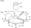
FIG. 2 is an exploded perspective view of a defoamer for a fermenter mounted on the microorganism fermenter ofFIG. 1 . -
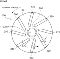
FIGS. 3 to 5 are views illustrating the defoamer for a fermenter ofFIG. 2 , in whichFIG. 3 is a plan view,FIG. 4 is a bottom view, andFIG. 5 is a side perspective view. -
FIG. 6 is a view illustrating an actual appearance of a conventional DFB defoamer. -
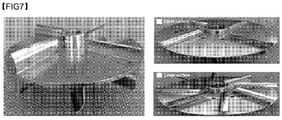
FIG. 7 is a view illustrating an actual appearance of a fermenter according to an embodiment of the present invention. -
FIG. 8 is a view illustrating an experiment obtained by measuring foam removal efficiency by using the defoamer ofFIG. 7 . -
Fig. 9 is a view illustrating an experimental result ofFIG. 8 . - A
defoamer 1000 for a fermenter according to an embodiment of the present invention will be described in detail with reference to the accompanying drawings. - Referring to
FIGS. 2 to 5 , thedefoamer 1000 for a fermenter according to the embodiment of the present invention includes abody 100, asupport 200, a plurality offirst veins second veins - The
body 100 has a disk shape, and a first hollow 110 is formed at a central portion of thebody 100. The first hollow 110 is a part at which thedefoamer 1000 for a fermenter is mounted to a rotary shaft of thefermenter 2000, which will be described below. - The
support 200 is a part which extends from anupper surface 120 and alower surface 130 of thebody 100. A second hollow 210 connected with the first hollow 110 is formed at a central portion of thesupport 200. - The
first veins defoamer 1000 for a fermenter when thedefoamer 1000 is rotated, and remove foams (f) produced by a fermentation process. Broth (b) is accommodated in the interior of thefermenter 2000 in which thedefoamer 1000 for a fermenter is installed, and foams (f) are formed by the fermentation of microorganisms. If thedefoamer 1000 for a fermenter is rotated, thefirst veins fermenter 2000 and the outer periphery ofdefoamer 1000 are secondarily uniformly defoamed. - The
first veins lower surface 130 of thebody 100. Then, any one of the plurality offirst veins body 100 while being spaced apart from another adjacent first vein at a uniform interval. Accordingly, flows of defoaming which suction and remove a predetermined amount of foams (f) are uniformly produced, and only a predetermined amount of broth foams (f), which are removed, are suctioned and are discharged to the outside in a semi-liquid state. Then, the foams (f) floated around are secondarily defoamed by the centrifugal force. - The
first veins body 100 while being spaced apart from thesupport 200 by a predetermined interval. That is, as illustrated inFIG. 3 , a predetermined space is formed between thefirst veins support 200. - The
first veins body 100, and each includes an upper end part having a first curvature, which is a curvature that is perpendicular to thebody 100, and having a predetermined height, and a lower end part connected to the upper end part, and extending while having a second curvature, which is different from the first curvature. - The
first veins body 100 to be spaced apart from imaginary lines connected the central portion of thebody 100 and outer distal ends of the inner surfaces of thefirst veins - Like first veins, the
second veins defoamer 1000 for a fermenter when thedefoamer 1000 is rotated, and remove foams (f) produced by a fermentation process. Thesecond veins upper surface 120 of thebody 100. - The structures of the
second veins - Referring to
FIG. 1 , amicroorganism fermenter 2000 according to an embodiment of the present invention will be described in detail.FIG. 1 is a view schematically illustrating themicroorganism fermenter 2000. - The
microorganism fermenter 2000 according to the embodiment of the present invention includes a container, a rotary shaft, one or more agitation blades, and adefoamer 1000 for a fermenter. - The rotary shaft is located at a central portion of the container. Locations at which the agitation blades, which will be described below, and the
defoamer 1000 for a fermenter are mounted are provided. - The agitation blades are parts mounted to the rotary shaft. Each of the agitation blades has one or more blades of a predetermined area, and agitates a fermentation target material accommodated in the container through rotation.
- Experiments were carried out by using a disc foam breaker (DFB) defoamer which is an conventional product and the
defoamer 1000 for a fermenter according to the embodiment of the present invention to verify the excellency of thedefoamer 1000 for a fermenter according to the embodiment of the present invention. - As illustrated in
FIG. 6 , the disc foam breaker (DFB) defoamer which is an conventional product is a product in which a vein is not formed on the upper surface thereof and four veins are formed only on the lower surface thereof. - The
defoamer 1000 for a fermenter according to the embodiment of the present invention is as illustrated inFIG. 7 . - The foam removal effects were observed after installing the DFB defoamer and the
defoamer 1000 for a fermenter according to the embodiment of the present invention at the same locations of fermenters of the capacity of 30 L and introducing broth for lysine production strains of 15 L, and while adding culture media of 0.5 L over time. The same amount of foam reduction agent was added to the initial broth, and saccharide for growth of microorganisms was added while the foam reduction agent is not added. - As illustrated in
FIG. 8 , the DFB defoamer started to be submerged 20 minutes after the culture media of a total of 1.5 L was additionally added, and the process could not be performed further due to an overflow phenomenon, in which the foams overflows from thefermenter 25 minutes from the culture media of a total of 1.5 L was additionally added. - Meanwhile, the
defoamer 1000 for a fermenter according to the embodiment of the present invention started to be submerged 35 minutes after the culture media of a total of 4.0 L was additionally added, but it can be identified that an overflow phenomenon which was severe so that the foams overflow the fermenter did not occur even if the culture media of a total of 4.0 L is additionally introduced. - As illustrated in
FIG. 9 , it can be identified in the verification experiment of thedefoamer 1000 for a fermenter according to the embodiment of the present invention that the overflow time delay effect was more excellent than that of the conventional DFB defoamer by 2 times or more, it can be identified that the capacity of the broth increased by 15% or more, and it can be also identified that the foam reduction agent could be saved by 20%. - Although the embodiments illustrated in the drawings have been described in the specification for reference such that a person skilled in the art can easily understand and realize the present invention, they are merely exemplary and a person skilled in the art can understand that various modifications and equivalent embodiments are also made from the embodiments of the present invention. Therefore, the scope of the present invention should be determined according to the claims.
-
- 100: body
- 110: first hollow
- 120: upper surface
- 130: lower surface
- 200: support
- 210: second hollow
- 310, 320, 330, 340, 350, 360, 370, 380: first vein
- 410, 420, 430, 440: second vein
- 1000: defoamer for a fermenter
- 2000: microorganism fermenter
Claims (12)
- A defoamer for a fermenter comprising:a body (100) having a first hollow (110) at a central portion thereof and having a disk shape;a support (200) having a second hollow (210) connected with the first hollow (110), and extending from an upper surface (120) and a lower surface (130) of the body (100); anda plurality of first veins (310, 320, 330, 340, 350, 360, 370, and 380) mounted on the lower surface (130) of the body (100).
- The defoamer for a fermenter of claim 1, wherein the plurality of first veins (310, 320, 330, 340, 350, 360, 370, and 380) are mounted on the body (100) while being spaced apart from the support (200) by a predetermined interval.
- The defoamer for a fermenter of claim 1, wherein any one of the plurality of first veins (310, 320, 330, 340, 350, 360, 370, and 380) is mounted to the body (100) while being spaced apart from another adjacent first vein at a uniform interval.
- The defoamer for a fermenter of claim 1, wherein the plurality of first veins (310, 320, 330, 340, 350, 360, 370, and 380) are formed in a radial direction of the body (100), and each of the plurality of first veins (310, 320, 330, 340, 350, 360, 370, and 380) has a predetermined height in a direction that is perpendicular to a radial direction of the body (100), and
wherein each of lower ends of the plurality of first veins (310, 320, 330, 340, 350, 360, 370, and 380) have a curved surface. - The defoamer for a fermenter of claim 1, wherein the plurality of first veins (310, 320, 330, 340, 350, 360, 370, and 380) are mounted on the body (100) while being eccentric from a radial direction, of which the center of rotation is the central portion of the body (100), by a predetermined angle (α).
- The defoamer for a fermenter of claim 5, wherein the predetermined angle (α) is 10 to 45 degrees.
- The defoamer for a fermenter of claim 1, further comprising:
a plurality of second veins (410, 420, 430, and 440) mounted on the upper surface (120) of the body (100). - The defoamer for a fermenter of claim 1, wherein the body (100) includes a separation/coupling part which separates and couples the defoamer for a fermenter.
- The defoamer for a fermenter of claim 1, wherein the length of each of lower ends of the plurality of first veins (310, 320, 330, 340, 350, 360, 370, and 380) becomes longer as it goes toward a radial direction of the body (100).
- A microorganism fermenter comprising the defoamer for a fermenter of any one of claims 1 to 9, the microorganism fermenter comprising:a container in which a fermentation target material is accommodated;a rotary shaft located at a central portion of the container; andone or more agitation blades mounted on the rotary shaft to be rotatable,wherein the body of the defoamer for a fermenter is mounted on the rotary shaft to be located at a height that is not less than the height of initial broth located in the container.
- A microorganism cultivating method using the microorganism fermenter of claim 10.
- A method for manufacturing a fermentation target object through the microorganism cultivating method of claim 11.
Applications Claiming Priority (2)
| Application Number | Priority Date | Filing Date | Title |
|---|---|---|---|
| KR1020170060487A KR101822334B1 (en) | 2017-05-16 | 2017-05-16 | Defoamer for fermenter, and microorganism fermenter using defoamer |
| PCT/KR2018/005263 WO2018212495A1 (en) | 2017-05-16 | 2018-05-08 | Foam breaker for fermentation tank and microorganism fermentation tank using foam breaker for fermentation tank |
Publications (2)
| Publication Number | Publication Date |
|---|---|
| EP3626810A1 true EP3626810A1 (en) | 2020-03-25 |
| EP3626810A4 EP3626810A4 (en) | 2021-01-27 |
Family
ID=61025553
Family Applications (1)
| Application Number | Title | Priority Date | Filing Date |
|---|---|---|---|
| EP18802811.2A Pending EP3626810A4 (en) | 2017-05-16 | 2018-05-08 | Foam breaker for fermentation tank and microorganism fermentation tank using foam breaker for fermentation tank |
Country Status (7)
| Country | Link |
|---|---|
| US (1) | US11578299B2 (en) |
| EP (1) | EP3626810A4 (en) |
| JP (1) | JP7203821B2 (en) |
| KR (1) | KR101822334B1 (en) |
| CN (1) | CN110536959B (en) |
| BR (1) | BR112019020389B1 (en) |
| WO (1) | WO2018212495A1 (en) |
Families Citing this family (11)
| Publication number | Priority date | Publication date | Assignee | Title |
|---|---|---|---|---|
| KR101822334B1 (en) | 2017-05-16 | 2018-01-26 | 씨제이제일제당 (주) | Defoamer for fermenter, and microorganism fermenter using defoamer |
| CN112410200B (en) * | 2020-10-16 | 2021-08-10 | 广州市丰兆电子科技有限公司 | New material production is with fermentation process bubble remove device |
| KR102278097B1 (en) * | 2021-01-21 | 2021-07-15 | (주)창세종합환경 | Wastewater microbial incubator |
| KR102431869B1 (en) * | 2021-01-21 | 2022-08-11 | (주)창세종합환경 | Microbial incubator |
| CN113274766A (en) * | 2021-04-22 | 2021-08-20 | 陈程 | Electromagnetic induction type double-medium plasma gas-liquid purification device |
| KR102431868B1 (en) * | 2021-06-29 | 2022-08-11 | (주)창세종합환경 | Microbial incubator equipped with foam removal unit |
| CN115193286B (en) * | 2022-07-08 | 2025-07-25 | 格莱德(福建)生物科技有限公司 | A agitating unit for cat feed processing |
| CN118356833A (en) * | 2023-04-04 | 2024-07-19 | 陈士红 | A chemical defoamer packaging and filling device |
| CN116694434B (en) * | 2023-07-31 | 2024-02-20 | 山东博精化工机械有限公司 | Biological method acrylamide stirring fermentation tank |
| CN119020149B (en) * | 2024-08-20 | 2025-03-18 | 扬州美瑞生物科技有限公司 | A microbial fermentation mechanism for producing sodium hyaluronate gel |
| CN118956555A (en) * | 2024-10-17 | 2024-11-15 | 辽宁恒润农业有限公司 | A microbial fermentation tank |
Family Cites Families (24)
| Publication number | Priority date | Publication date | Assignee | Title |
|---|---|---|---|---|
| US2750328A (en) * | 1952-03-20 | 1956-06-12 | Nat Dairy Res Lab Inc | Aerating method and apparatus |
| JP3116103B2 (en) * | 1991-11-22 | 2000-12-11 | 味の素株式会社 | Culture device and defoaming control method in fermentation production by aerobic culture |
| JP3337357B2 (en) * | 1995-11-09 | 2002-10-21 | 住友ベークライト株式会社 | Rotating disk type defoaming device for reaction tank |
| JP3654789B2 (en) * | 1999-04-08 | 2005-06-02 | 鹿島建設株式会社 | Sludge treatment method and apparatus |
| JP2000288593A (en) | 1999-04-08 | 2000-10-17 | Shinto Eco Techno:Kk | Air bubble treatment mechanism of excretion fermentative treatment apparatus |
| DE10149132B4 (en) * | 2001-10-05 | 2006-05-04 | Sartorius Ag | Device for defoaming a bioreactor |
| JP2007216113A (en) * | 2006-02-15 | 2007-08-30 | Sanshu Densen Kk | Defoaming apparatus |
| CN101003780B (en) * | 2007-01-24 | 2011-12-14 | 王培生 | Defoamer being installed microbe fermenting installation air discharged from center of pot top |
| US8785180B2 (en) * | 2007-06-18 | 2014-07-22 | Shanghai Guoqiang Bioengineering Equipment Co., Ltd. | Biochemical reactor |
| CN101948747B (en) * | 2010-08-13 | 2014-09-03 | 李明忠 | Intelligent clean biological fermentation production increase equipment |
| CN101948738A (en) * | 2010-09-04 | 2011-01-19 | 颜金钰 | Annular jet flow type fermentation tank and fermentation stirring system thereof |
| CN202297584U (en) * | 2011-10-18 | 2012-07-04 | 江苏浩特隆搅拌设备有限公司 | Stirrer combination for large-scale fermentation tank |
| CN103958041B (en) * | 2011-11-24 | 2016-10-19 | 王利 | Stirring impeller with grooved blades |
| CN202379983U (en) * | 2011-11-30 | 2012-08-15 | 山东福洋生物科技有限公司 | Defoaming device for fermentation tank |
| KR101348858B1 (en) * | 2012-03-16 | 2014-01-07 | 임정식 | mixing device of microorganism culture medium |
| KR20140099967A (en) * | 2013-02-04 | 2014-08-14 | 주식회사 와이엘환경 | Continuous type agritating appararatus for water treatment |
| KR101392425B1 (en) * | 2013-05-28 | 2014-05-07 | 김호신 | Bubble removal device that can be used to decompose the pig manure |
| KR200487606Y1 (en) * | 2013-12-26 | 2018-10-11 | 스미토모 쥬기카이 프로세스 기키 가부시키가이샤 | Stirring blade and stirring device |
| KR101718479B1 (en) * | 2014-11-11 | 2017-03-21 | 주식회사 월드바이오텍 | Fermenter having part for removing bubbles |
| CN205088244U (en) * | 2015-10-23 | 2016-03-16 | 宁波中瑞生物科技有限公司 | Horizontal liquid state fermentation jar fire fighting equipment |
| CN205590683U (en) * | 2016-04-19 | 2016-09-21 | 山东欧迈机械股份有限公司 | Defoaming paddle agitator |
| CN205590638U (en) | 2016-05-12 | 2016-09-21 | 中海海洋(荣成)健康产业有限公司 | Fish oil deodorization device |
| CN205857352U (en) * | 2016-07-29 | 2017-01-04 | 宏岳塑胶集团股份有限公司 | Floor drain for washing machine with self-cleaning function |
| KR101822334B1 (en) * | 2017-05-16 | 2018-01-26 | 씨제이제일제당 (주) | Defoamer for fermenter, and microorganism fermenter using defoamer |
-
2017
- 2017-05-16 KR KR1020170060487A patent/KR101822334B1/en active Active
-
2018
- 2018-05-08 BR BR112019020389-3A patent/BR112019020389B1/en active IP Right Grant
- 2018-05-08 US US16/614,195 patent/US11578299B2/en active Active
- 2018-05-08 EP EP18802811.2A patent/EP3626810A4/en active Pending
- 2018-05-08 CN CN201880024196.4A patent/CN110536959B/en active Active
- 2018-05-08 JP JP2020507975A patent/JP7203821B2/en active Active
- 2018-05-08 WO PCT/KR2018/005263 patent/WO2018212495A1/en not_active Ceased
Also Published As
| Publication number | Publication date |
|---|---|
| BR112019020389A2 (en) | 2020-04-28 |
| US20200071653A1 (en) | 2020-03-05 |
| KR101822334B1 (en) | 2018-01-26 |
| EP3626810A4 (en) | 2021-01-27 |
| JP2020517305A (en) | 2020-06-18 |
| US11578299B2 (en) | 2023-02-14 |
| CN110536959B (en) | 2023-04-11 |
| JP7203821B2 (en) | 2023-01-13 |
| CN110536959A (en) | 2019-12-03 |
| WO2018212495A1 (en) | 2018-11-22 |
| BR112019020389B1 (en) | 2023-03-14 |
Similar Documents
| Publication | Publication Date | Title |
|---|---|---|
| US11578299B2 (en) | Defoamer for fermenter, and microorganism fermenter using defoamer for fermenter | |
| US5075234A (en) | Fermentor/bioreactor systems having high aeration capacity | |
| US20080233631A1 (en) | Ventilating/Stirring Culture Tank | |
| JP3936842B2 (en) | Apparatus for culturing tissue cells and microorganisms in suspension | |
| WO2015160614A1 (en) | Vessel for growth of biological entities | |
| US3433148A (en) | Main and after fermentation tank for beer brewery | |
| CA2852406C (en) | Method involving contact between grain raw material liquid and yeast, grain raw material liquid and sparkling beverage | |
| Maule | A century of fermenter design | |
| US4904600A (en) | Bioreactor for continuous processing of a reactant fluid | |
| US3415654A (en) | Deep vat fermentation of beer | |
| JPH09131502A (en) | Rotary-disk type defoaming device for reaction vessel | |
| Inoue et al. | Ester formation by a yeast Hansenula mrakii IFO 0895: contribution of esterase for iso-amyl acetate production in sake brewing | |
| JPH06253815A (en) | Culture container with baffle | |
| US2346011A (en) | Process for cultivation of fatforming molds | |
| Chen et al. | Enzymatic hydrolysis of triglycerides by Rhizopus delemar immobilized on biomass support particles | |
| Kaur et al. | Industrial Bioreactors for Submerged Fermentations | |
| Fukuda et al. | Phospholipase D production using immobilized cells of Streptoverticillium cinnamoneum | |
| CN204448001U (en) | Reactor in a kind of freeze-drying production of raw medicine technique | |
| CN207828275U (en) | A kind of biological fermentation tank of uniform distribution | |
| CN221166850U (en) | Crystal ingot corrosion barrel | |
| CN105647783A (en) | Methanol protein airlift internal circulation fermentation tank | |
| BR102012033485A2 (en) | BIOPRODUCTS EQUIPMENT AND HYBRID PROCESS | |
| CN205398626U (en) | Mechanical draft stirs fermentation cylinder | |
| CN216513814U (en) | Shell breaker and fermentation device | |
| JP3754850B2 (en) | Immobilization carrier, method for producing fermentation product, and fermentation product |
Legal Events
| Date | Code | Title | Description |
|---|---|---|---|
| STAA | Information on the status of an ep patent application or granted ep patent |
Free format text: STATUS: THE INTERNATIONAL PUBLICATION HAS BEEN MADE |
|
| PUAI | Public reference made under article 153(3) epc to a published international application that has entered the european phase |
Free format text: ORIGINAL CODE: 0009012 |
|
| STAA | Information on the status of an ep patent application or granted ep patent |
Free format text: STATUS: REQUEST FOR EXAMINATION WAS MADE |
|
| 17P | Request for examination filed |
Effective date: 20190913 |
|
| AK | Designated contracting states |
Kind code of ref document: A1 Designated state(s): AL AT BE BG CH CY CZ DE DK EE ES FI FR GB GR HR HU IE IS IT LI LT LU LV MC MK MT NL NO PL PT RO RS SE SI SK SM TR |
|
| AX | Request for extension of the european patent |
Extension state: BA ME |
|
| DAV | Request for validation of the european patent (deleted) | ||
| DAX | Request for extension of the european patent (deleted) | ||
| A4 | Supplementary search report drawn up and despatched |
Effective date: 20210114 |
|
| RIC1 | Information provided on ipc code assigned before grant |
Ipc: C12M 1/21 20060101AFI20201222BHEP Ipc: C12M 1/06 20060101ALI20201222BHEP |
|
| P01 | Opt-out of the competence of the unified patent court (upc) registered |
Effective date: 20230606 |