EP3626698A1 - Diffusion plate and purification tower including same - Google Patents
Diffusion plate and purification tower including same Download PDFInfo
- Publication number
- EP3626698A1 EP3626698A1 EP18827439.3A EP18827439A EP3626698A1 EP 3626698 A1 EP3626698 A1 EP 3626698A1 EP 18827439 A EP18827439 A EP 18827439A EP 3626698 A1 EP3626698 A1 EP 3626698A1
- Authority
- EP
- European Patent Office
- Prior art keywords
- tube
- fluid
- tubes
- length
- dispersion plate
- Prior art date
- Legal status (The legal status is an assumption and is not a legal conclusion. Google has not performed a legal analysis and makes no representation as to the accuracy of the status listed.)
- Granted
Links
Images


Classifications
-
- C—CHEMISTRY; METALLURGY
- C07—ORGANIC CHEMISTRY
- C07C—ACYCLIC OR CARBOCYCLIC COMPOUNDS
- C07C7/00—Purification; Separation; Use of additives
- C07C7/20—Use of additives, e.g. for stabilisation
-
- B—PERFORMING OPERATIONS; TRANSPORTING
- B01—PHYSICAL OR CHEMICAL PROCESSES OR APPARATUS IN GENERAL
- B01D—SEPARATION
- B01D3/00—Distillation or related exchange processes in which liquids are contacted with gaseous media, e.g. stripping
- B01D3/008—Liquid distribution
-
- B—PERFORMING OPERATIONS; TRANSPORTING
- B01—PHYSICAL OR CHEMICAL PROCESSES OR APPARATUS IN GENERAL
- B01D—SEPARATION
- B01D3/00—Distillation or related exchange processes in which liquids are contacted with gaseous media, e.g. stripping
- B01D3/009—Distillation or related exchange processes in which liquids are contacted with gaseous media, e.g. stripping in combination with chemical reactions
-
- C—CHEMISTRY; METALLURGY
- C07—ORGANIC CHEMISTRY
- C07C—ACYCLIC OR CARBOCYCLIC COMPOUNDS
- C07C11/00—Aliphatic unsaturated hydrocarbons
- C07C11/12—Alkadienes
- C07C11/16—Alkadienes with four carbon atoms
-
- C—CHEMISTRY; METALLURGY
- C07—ORGANIC CHEMISTRY
- C07C—ACYCLIC OR CARBOCYCLIC COMPOUNDS
- C07C7/00—Purification; Separation; Use of additives
- C07C7/148—Purification; Separation; Use of additives by treatment giving rise to a chemical modification of at least one compound
-
- Y—GENERAL TAGGING OF NEW TECHNOLOGICAL DEVELOPMENTS; GENERAL TAGGING OF CROSS-SECTIONAL TECHNOLOGIES SPANNING OVER SEVERAL SECTIONS OF THE IPC; TECHNICAL SUBJECTS COVERED BY FORMER USPC CROSS-REFERENCE ART COLLECTIONS [XRACs] AND DIGESTS
- Y02—TECHNOLOGIES OR APPLICATIONS FOR MITIGATION OR ADAPTATION AGAINST CLIMATE CHANGE
- Y02P—CLIMATE CHANGE MITIGATION TECHNOLOGIES IN THE PRODUCTION OR PROCESSING OF GOODS
- Y02P20/00—Technologies relating to chemical industry
- Y02P20/10—Process efficiency
Definitions
- the present invention relates to a dispersion plate, and particularly, to a dispersion plate used in a butadiene purification column.
- Butadiene has been used as an intermediate of numerous petrochemicals such as synthetic rubber and electronic materials, which is one of the most important basic oils in a petrochemical market, and the demand and value thereof has been gradually increasing.
- Butadiene may be obtained by purifying butadiene in a C4 mixture.
- a first extraction system, a second extraction system, and a purification system are included.
- a process of removing impurities is performed in order to increase the purity of butadiene, which is carried out in a purification column.
- the purification column includes a dispersion plate and a catalyst layer therein, wherein steam injected from a lower portion thereof moves to an upper portion thereof, butadiene injected from the upper portion thereof moves to the lower portion thereof, and in the catalyst layer, a reaction for removing impurities occurs.
- the dispersion plate separates the flow of steam and butadiene from each other, such that the purification is performed efficiently.
- the dispersion plate includes a plurality of tubes through which butadiene and steam flow, and some of the tubes through which butadiene flows may be clogged by a popcorn-type impurity (hereinafter, referred to as a popcorn polymer) produced during the process.
- a popcorn-type impurity hereinafter, referred to as a popcorn polymer
- the present invention has been made in an effort to provide a dispersion plate for butadiene purification column in which purification efficiency is not reduced even if some of the tubes through which butadiene is discharged are clogged to raise a liquid level, and a purification column including the same.
- An exemplary embodiment of the present invention provides a dispersion plate for a purification column including a support plate, at least one first fluid tube penetrating through the support plate, and a plurality of second fluid tubes arranged to be spaced apart from the first fluid tube and surround the first fluid tube, wherein a length of at least one of the second fluid tubes is longer than lengths of another second fluid tubes, and is shorter than or equal to a length of the first fluid tube.
- the second fluid tube may be arranged at a predetermined interval along a circumference of the first fluid tube.
- the second fluid tube may include a first tube having a first length and a second tube having a second length longer than the first length, wherein the first tube and the second tube are alternately arranged along the circumference of the first fluid tube.
- Each of the second fluid tubes may have an elliptical inlet in which a first end point positioned to be spaced apart from one surface of the support plate by a first distance, and a second end point positioned to be spaced apart from the one surface of the support plate by a second distance longer than the first distance are connected to each other.
- the second end point of the first tube may be positioned on the same line as the first end point of the second tube.
- Diameters of the first tube and the second tube may be the same.
- the second fluid tube may include a plurality of first tubes surrounding the first fluid tube, arranged at a predetermined interval, and having the same length; and a plurality of second tubes each positioned between adjacent first tubes and having different lengths, wherein a length of the second tube is longer than a length of the first tube.
- the first tube may be arranged at an angle in which the first fluid tube having a circular cross-section is evenly divided.
- the second fluid tube may include the same number of the first tube and the second tube.
- a purification column including a purification chamber having a lower portion into which steam is injected and an upper portion into which butadiene is injected, at least one dispersion plate installed across the inside of the purification chamber, and at least one catalyst layer positioned to be spaced apart from the dispersion plate and removing impurities of butadiene, wherein the dispersion plate includes a support plate, at least one first fluid tube penetrating through the support plate, and a plurality of second fluid tubes arranged to be spaced apart from the first fluid tube and surround the first fluid tube, a length of at least one of the second fluid tubes being longer than lengths of another second fluid tubes, and being shorter than or equal to a length of the first fluid tube.
- the butadiene tubes may have various lengths, whereby deterioration in purification efficiency may be minimized even if the tube is clogged due to a popcorn polymer.
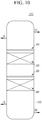
- FIG. 1 is a schematic configuration diagram showing a purification column according to an exemplary embodiment of the present invention.
- a purification column 1000 includes a purification chamber 100, a dispersion plate 200 installed across the purification chamber 100, inlets H1 and H2 and outlets H3 and H4 for injecting and discharging fluid into/from the purification chamber 100, and a catalyst layer 300 for removing impurities.
- the purification chamber 100 provides a space in which butadiene is purified by reacting with a catalyst and separated from an external environment.
- the purification chamber 100 includes a first inlet H1 through which butadiene is supplied, a second inlet H2 through which steam is injected, a first outlet H3 through which steam is discharged, and a second outlet H4 through which purified butadiene is discharged.
- the first inlet H1 is positioned at an upper portion of the purification chamber
- the second outlet H4 is positioned at a lower portion of the purification chamber to allow butadiene supplied from the upper portion of the purification chamber to the lower portion thereof and then purified to be discharged through the second outlet H4 at the lower portion thereof.
- the second inlet H2 is positioned at the lower portion of the purification chamber, and the first outlet H3 is positioned at the upper portion of the purification chamber 100 to allow steam supplied to the lower portion of the purification chamber 100 and then moving to the upper portion of the purification chamber 100 to be discharged through the first outlet H3.
- the catalyst layer 300 may be selected depending on the impurities to be removed from butadiene supplied, and may be a catalyst containing a metal.
- the dispersion plate 200 which is to separate the catalyst layer 300, butadiene and steam from one another, is installed across the purification chamber 100.
- FIG. 2 is a schematic perspective diagram showing a dispersion plate according to an exemplary embodiment of the present invention.
- FIG. 3 is a diagram for comparing and illustrating a length of a fluid tube included in FIG. 2 .
- FIG. 4 is a layout diagram showing a fluid tube included in one unit group included in FIG. 2 .
- the dispersion plate 200 may include a support plate 20, at least one first fluid tube 21 penetrating through the support plate 20, and a plurality of second fluid tubes 23 arranged to be spaced apart from the first fluid tube 21 and surround the first fluid tube 21.
- the second fluid tubes 23 may be arranged, at a predetermined interval, along the circumference of the first fluid tube 21.
- Vapor (steam) may flow through the first tube 21 and butadiene may flow through the second fluid tube 23.
- a diameter D1 of the first tube 21 may be larger than a diameter D2 of the second fluid tube 23.
- a length of the second fluid tube 23 may be shorter than a length of the first fluid tube 21 and a length L1 of at least one of the second fluid tubes 23 may be longer than a length L2 of another second fluid tube 23, but is not limited thereto, and three, four, or more second fluid tubes having different lengths may be formed.
- the second fluid tubes having four different lengths will be described as an example.
- the second fluid tube having the shortest length is referred to as a first tube 23a
- the second fluid tubes having different lengths, in the order of increasing lengths are each referred to as a second tube 23b, a third tube 23c and a fourth tube 23d.
- the second fluid tube 23 is cut obliquely and an inlet of the second fluid tube 23 may have an elliptical inlet in which a first end point X1 positioned to be spaced apart from one surface of the support plate 20 by a first distance LD1, and a second end point X2 positioned to be spaced apart from the one surface of the support plate 20 by a second distance LD2 longer than the first distance LD1 are connected each other.
- the second end point is positioned relatively adjacent to the first fluid tube 21, and the first end point is positioned relatively far from the first fluid tube 21. Therefore, the elliptical inlet of the second fluid tube 23 is arranged so as not to face the first fluid tube 21, thereby allowing butadiene to easily flow in.
- a difference between a length L21 of the first tube 23a and a length L22 of the second tube 23b, a difference between a length L22 of the second tube 23b and a length L23 of the third tube 23c, and a difference between a length L23 of the third tube 23c and a length L24 of the fourth tube 23d may be a difference LD (hereinafter, referred to as a height of the elliptical inlet) between the second distance LD2 and the first distance LD1, respectively.
- a difference LD hereinafter, referred to as a height of the elliptical inlet
- the second end point X2 of the first tube 23a may be positioned on the same line as the first end point X1 of the second tube 23b
- the second end point X2 of the second tube 23b may be positioned on the same line as the first end point X1 of the third tube 23c
- the second end point X2 of the third tube 23c may be positioned on the same line as the first end point X1 of the fourth tube 23d.
- a second fluid tube having a longer length than a second fluid tube having a reference length when arranging a second fluid tube having a longer length than a second fluid tube having a reference length, a second fluid tube having a longer length than a second fluid tube having the reference length (or previously arranged) by a height LD of the elliptical inlet may be arranged, and the second end point X2 of the second fluid tube having the reference length and the first end point X1 of the second fluid tube arranged thereafter may be arranged so as to be positioned on the same line.
- the dispersion plate 200 may include a plurality of unit groups G depending on a purification capacity of the purification column.
- the dispersion plate 200 may include seven unit groups G, and, the unit group G may be arranged at a predetermined interval in the support plate.
- the second fluid tubes 23 having different lengths and included in the unit group G may include at least one second fluid tubes 23 having the same length.
- one unit group G may include three first tubes 23a and three second tubes 23b, respectively, and the first tubes 23a and the second tube 23b may be arranged alternately.
- one unit group G may include three first tubes 23a, one second tube 23b, one third tube 23c, and one fourth tube 23d, and the second tube 23b, the third tube 23c, and the fourth tube 23d may be arranged between adjacent first tubes 23a.
- the function of the dispersion plate may be extended although some of the second fluid tube 23 is clogged due to popcorn polymer necessarily produced in addition to butadiene.
- FIG. 5 to FIG. 7 are schematic diagrams for explaining a fluid flow in the dispersion plate according to an exemplary embodiment of the present invention.
- the fluid tubes arranged in the order of their lengths are shown.
- butadiene is supplied from the upper portion of the purification column and stored on the support plate 20, and when the butadiene reaches a predetermined level or more, it is transferred to the catalyst layer at the lower portion of the purification column, through the second fluid tube 23.
- Some of the plurality of second fluid tubes may be clogged by the popcorn polymer. Clogging due to the popcorn polymer results in a difference in a flux of the supplied butadiene and the butadiene discharged through the second fluid tube 23. Therefore, all of the supplied butadiene is not transferred to the catalyst layer but are stored, result in raising the height of the liquid level W of butadiene.
- the second fluid tube 23 when the second fluid tube 23 is installed in multi-stages, butadiene is discharged through the first tube 23a in the steady state.
- the liquid level W rises and, the liquid level W reaches the inlet of the second tube 23b as shown in FIG. 6 and butadiene starts to be discharged through the second tube 23b.
- the liquid level height may be raised to 150 mm. Therefore, at the inlet of the second tube 23b, the first end point may be positioned at 150 mm, which is the liquid level height.
- butadiene may be discharged even while the liquid level rises and reaches the first fluid tube, thereby reducing the deterioration in purification efficiency.
- the second end point X2 of a second fluid tube which relatively first starts to discharge (for example, a first tube 23a which starts to discharge prior to the second tube 23b), and the first end point X1 of the second tube 23b starting the next discharge may be positioned on the same line. Therefore, even if the liquid level rises, it is possible to perform a discharge immediately, thereby preventing the deterioration in the purification efficiency.
- the popcorn polymer together with butadiene may reach the catalyst layer through the first fluid tube, thereby reducing purification efficiency.
- the rise of the liquid level may delay as much as possible, thereby delaying the deterioration in purification efficiency due to the transfer of the popcorn polymer to the catalyst layer.
- FIG. 8 is a schematic layout diagram showing a dispersion plate according to another embodiment of the present invention.
- FIG. 9 is a diagram for comparing and illustrating a length of a fluid tube included in FIG. 8 .
- the dispersion plate shown in FIG. 8 and FIG. 9 is mostly the same as that shown in FIG. 2 to FIG. 4 , and thus only different parts will be described in detail.
- one unit group is described as an example, and the dispersion plate may include such unit group in plural.
- a dispersion plate 202 may include the first fluid tube 21 and the second fluid tube 23, and the second fluid tube 23 may include tubes 23a, 23b, 23c, 23d, and 23e having different lengths, and may be installed in multi-stages.
- the second fluid tube 23 in FIG. 8 and FIG. 9 further includes one stage than the second fluid tube in FIG. 2 to FIG. 4 .
- the reason may be that the distance from the first tube 23a to the first fluid tube 21 is longer than the distance from the first tube 23a to the first fluid tube 21 in FIG. 2 to FIG 4 , or the height LD of the inlet is short.
- the arrangement of the second fluid tubes in FIG. 2 to FIG. 4 and the second fluid tubes in FIG. 8 and FIG. 9 may be performed in the same manner.
- a reference tube is arranged at a predetermined interval along the circumference of the first fluid tube 21.
- the reference tube may be the first tubes 23a, and all of the first tubes 23a may have the same length and have the shortest length among the second fluid tubes.
- the second fluid tubes may be arranged radially from the center of the first fluid tube.
- the first tubes 23a since the number of the first tube 23a, which is the reference tube, is three, the first tubes 23a may be arranged at a position where the first fluid tube having a circular cross section is divided by 120 degrees.
- the first tubes 23a since the number of the first tube, which is the reference tube, is four, the first tubes 23a may be arranged at a position where the first fluid tube having a circular cross section is divided by 90 degrees.
- Intermediate tubes having longer lengths than the reference tube may be arranged between adjacent reference tubes, respectively.
- the intermediate tubes may be the second tube 23b, the third tube 23c, the fourth tube 23d, and the fifth tube 23e, all of these lengths may be different.
- the intermediate tubes having three different lengths may be arranged between adjacent reference tubes, respectively.
- the intermediate tubes having four different lengths may be arranged between adjacent reference tubes, respectively.
- the second fluid tubes having four stages in FIG. 4 and five stages in FIG. 8 are each escribed as an example, but is not limited thereto, and may include more or fewer number of stages.
- the reference tube may be arranged at an angle in which the first fluid tube having a circular cross-section is evenly divided, and the intermediate tubes may be arranged therebetween, the number of reference tubes and the number of intermediate tubes positioned between adjacent reference tubes may be the same.
- one intermediate tube is described except for the reference tube, but is not limited thereto, and depending on the flux of butadiene, there may be multiple intermediate tubes in each stage.
- the first fluid tube having a circular cross-section is described as an example, but is not limited thereto.
- the first fluid tube may have various cross-sections, such as a tetragon and pentagon.
- the second fluid tube may be arranged radially at a predetermined angle from the center of the first fluid tube, while surrounding the first fluid tube.
- the purification column having one dispersion plate is described, but is not limited thereto, and as shown in FIG. 10 , a plurality of dispersion plates may be installed, as necessary.
- FIG. 10 is a schematic configuration diagram showing a purification column according to another embodiment of the present invention.
- a purification column 1002 may include two dispersion plates 200 and may be installed in the order of the catalyst layer 300, the dispersion plate 200, the catalyst layer 300, and the dispersion plate 200 from the lower portion of the purification column.
Landscapes
- Chemical & Material Sciences (AREA)
- Organic Chemistry (AREA)
- Chemical Kinetics & Catalysis (AREA)
- Engineering & Computer Science (AREA)
- Analytical Chemistry (AREA)
- Oil, Petroleum & Natural Gas (AREA)
- Water Supply & Treatment (AREA)
- General Chemical & Material Sciences (AREA)
- Devices And Processes Conducted In The Presence Of Fluids And Solid Particles (AREA)
- Physical Or Chemical Processes And Apparatus (AREA)
- Organic Low-Molecular-Weight Compounds And Preparation Thereof (AREA)
Abstract
Description
- This application claims priority to and the benefit of Korean Patent Application No.
10-2017-0086529 - The present invention relates to a dispersion plate, and particularly, to a dispersion plate used in a butadiene purification column.
- Butadiene has been used as an intermediate of numerous petrochemicals such as synthetic rubber and electronic materials, which is one of the most important basic oils in a petrochemical market, and the demand and value thereof has been gradually increasing.
- Butadiene may be obtained by purifying butadiene in a C4 mixture. For purification, a first extraction system, a second extraction system, and a purification system are included.
- Here, in the purification system, a process of removing impurities is performed in order to increase the purity of butadiene, which is carried out in a purification column.
- The purification column includes a dispersion plate and a catalyst layer therein, wherein steam injected from a lower portion thereof moves to an upper portion thereof, butadiene injected from the upper portion thereof moves to the lower portion thereof, and in the catalyst layer, a reaction for removing impurities occurs.
- Here, the dispersion plate separates the flow of steam and butadiene from each other, such that the purification is performed efficiently.
- The dispersion plate includes a plurality of tubes through which butadiene and steam flow, and some of the tubes through which butadiene flows may be clogged by a popcorn-type impurity (hereinafter, referred to as a popcorn polymer) produced during the process.
- As such, when some of the tubes are clogged, the dispersion plate fails to function, a liquid level of butadiene rises, so that butadiene flows in the tube through which steam flows, thereby reducing purification efficiency.
- The present invention has been made in an effort to provide a dispersion plate for butadiene purification column in which purification efficiency is not reduced even if some of the tubes through which butadiene is discharged are clogged to raise a liquid level, and a purification column including the same.
- An exemplary embodiment of the present invention provides a dispersion plate for a purification column including a support plate, at least one first fluid tube penetrating through the support plate, and a plurality of second fluid tubes arranged to be spaced apart from the first fluid tube and surround the first fluid tube, wherein a length of at least one of the second fluid tubes is longer than lengths of another second fluid tubes, and is shorter than or equal to a length of the first fluid tube.
- The second fluid tube may be arranged at a predetermined interval along a circumference of the first fluid tube.
- The second fluid tube may include a first tube having a first length and a second tube having a second length longer than the first length, wherein the first tube and the second tube are alternately arranged along the circumference of the first fluid tube.
- Each of the second fluid tubes may have an elliptical inlet in which a first end point positioned to be spaced apart from one surface of the support plate by a first distance, and a second end point positioned to be spaced apart from the one surface of the support plate by a second distance longer than the first distance are connected to each other.
- The second end point of the first tube may be positioned on the same line as the first end point of the second tube.
- Diameters of the first tube and the second tube may be the same.
- The second fluid tube may include a plurality of first tubes surrounding the first fluid tube, arranged at a predetermined interval, and having the same length; and a plurality of second tubes each positioned between adjacent first tubes and having different lengths, wherein a length of the second tube is longer than a length of the first tube.
- The first tube may be arranged at an angle in which the first fluid tube having a circular cross-section is evenly divided.
- The second fluid tube may include the same number of the first tube and the second tube.
- Another embodiment of the present invention provides a purification column including a purification chamber having a lower portion into which steam is injected and an upper portion into which butadiene is injected, at least one dispersion plate installed across the inside of the purification chamber, and at least one catalyst layer positioned to be spaced apart from the dispersion plate and removing impurities of butadiene, wherein the dispersion plate includes a support plate, at least one first fluid tube penetrating through the support plate, and a plurality of second fluid tubes arranged to be spaced apart from the first fluid tube and surround the first fluid tube, a length of at least one of the second fluid tubes being longer than lengths of another second fluid tubes, and being shorter than or equal to a length of the first fluid tube.
- According to an embodiment of the present invention, in the dispersion plate installed in the butadiene purification column, the butadiene tubes may have various lengths, whereby deterioration in purification efficiency may be minimized even if the tube is clogged due to a popcorn polymer.
-
-
FIG. 1 is a schematic configuration diagram showing a purification column according to an exemplary embodiment of the present invention. -
FIG. 2 is a schematic perspective diagram showing a dispersion plate according to an exemplary embodiment of the present invention. -
FIG. 3 is a diagram for comparing and illustrating a length of a fluid tube included inFIG. 2 . -
FIG. 4 is a layout diagram showing a fluid tube included in one unit group included inFIG. 2 . -
FIG. 5 to FIG. 7 are schematic diagrams for explaining a fluid flow in a dispersion plate according to an exemplary embodiment of the present invention. -
FIG. 8 is a schematic layout diagram showing a dispersion plate according to another embodiment of the present invention. -
FIG. 9 is a diagram for comparing and illustrating a length of a fluid tube included inFIG. 8 . -
FIG. 10 is a schematic configuration diagram showing a purification column according to another embodiment of the present invention. - Hereinafter, exemplary embodiments of the present invention will be described in detail so as for those of ordinary skill in the art to easily implement, with reference to the accompanying drawings. The present invention may be embodied in many different forms and is not limited to the exemplary embodiments described herein.
- To clarify the present invention, parts not related to the description are omitted from the drawings, and the same or similar components are denoted by the same reference numerals throughout the specification.
- In addition, the size and thickness of each component shown in the drawings are arbitrarily shown for convenience of explanation, and thus the present invention is not necessarily limited to those shown in the drawings.
- Throughout the specification, when referring that a certain element is "connected" to another element, it includes not only "directly connected" but also "indirectly connected" between other members. In addition, when referring that a certain element "comprises" a certain component, this means that the element may further include another components instead of excluding another components, unless explicitly described to the contrary.
- Hereinafter, with reference to the accompanying drawings, a dispersion plate installed in a butadiene purification column according to an exemplary embodiment of the present invention will be described in detail.
-
FIG. 1 is a schematic configuration diagram showing a purification column according to an exemplary embodiment of the present invention. - Purification of butadiene according to an exemplary embodiment of the present invention is performed in the purification column. As shown in
FIG. 1 , apurification column 1000 according to an exemplary embodiment of the present invention includes apurification chamber 100, adispersion plate 200 installed across thepurification chamber 100, inlets H1 and H2 and outlets H3 and H4 for injecting and discharging fluid into/from thepurification chamber 100, and acatalyst layer 300 for removing impurities. - The
purification chamber 100 provides a space in which butadiene is purified by reacting with a catalyst and separated from an external environment. - The
purification chamber 100 includes a first inlet H1 through which butadiene is supplied, a second inlet H2 through which steam is injected, a first outlet H3 through which steam is discharged, and a second outlet H4 through which purified butadiene is discharged. - The first inlet H1 is positioned at an upper portion of the purification chamber, and the second outlet H4 is positioned at a lower portion of the purification chamber to allow butadiene supplied from the upper portion of the purification chamber to the lower portion thereof and then purified to be discharged through the second outlet H4 at the lower portion thereof.
- The second inlet H2 is positioned at the lower portion of the purification chamber, and the first outlet H3 is positioned at the upper portion of the
purification chamber 100 to allow steam supplied to the lower portion of thepurification chamber 100 and then moving to the upper portion of thepurification chamber 100 to be discharged through the first outlet H3. - The
catalyst layer 300 may be selected depending on the impurities to be removed from butadiene supplied, and may be a catalyst containing a metal. - The
dispersion plate 200, which is to separate thecatalyst layer 300, butadiene and steam from one another, is installed across thepurification chamber 100. -
FIG. 2 is a schematic perspective diagram showing a dispersion plate according to an exemplary embodiment of the present invention.FIG. 3 is a diagram for comparing and illustrating a length of a fluid tube included inFIG. 2 .FIG. 4 is a layout diagram showing a fluid tube included in one unit group included inFIG. 2 . - Referring to
FIG. 2 , thedispersion plate 200 may include asupport plate 20, at least onefirst fluid tube 21 penetrating through thesupport plate 20, and a plurality ofsecond fluid tubes 23 arranged to be spaced apart from thefirst fluid tube 21 and surround thefirst fluid tube 21. Here, thesecond fluid tubes 23 may be arranged, at a predetermined interval, along the circumference of thefirst fluid tube 21. - Vapor (steam) may flow through the
first tube 21 and butadiene may flow through thesecond fluid tube 23. - Referring to
FIG. 3 , a diameter D1 of thefirst tube 21 may be larger than a diameter D2 of thesecond fluid tube 23. A length of thesecond fluid tube 23 may be shorter than a length of thefirst fluid tube 21 and a length L1 of at least one of thesecond fluid tubes 23 may be longer than a length L2 of anothersecond fluid tube 23, but is not limited thereto, and three, four, or more second fluid tubes having different lengths may be formed. - Hereinafter, the second fluid tubes having four different lengths will be described as an example. For convenience of explanation, among the second fluid tubes having different lengths, the second fluid tube having the shortest length is referred to as a
first tube 23a, and in order of increasing length, the second fluid tubes having different lengths, in the order of increasing lengths, are each referred to as asecond tube 23b, athird tube 23c and afourth tube 23d. - Referring to
FIG. 2 andFIG. 3 , thesecond fluid tube 23 is cut obliquely and an inlet of thesecond fluid tube 23 may have an elliptical inlet in which a first end point X1 positioned to be spaced apart from one surface of thesupport plate 20 by a first distance LD1, and a second end point X2 positioned to be spaced apart from the one surface of thesupport plate 20 by a second distance LD2 longer than the first distance LD1 are connected each other. - Here, the second end point is positioned relatively adjacent to the
first fluid tube 21, and the first end point is positioned relatively far from thefirst fluid tube 21. Therefore, the elliptical inlet of thesecond fluid tube 23 is arranged so as not to face thefirst fluid tube 21, thereby allowing butadiene to easily flow in. A difference between a length L21 of thefirst tube 23a and a length L22 of thesecond tube 23b, a difference between a length L22 of thesecond tube 23b and a length L23 of thethird tube 23c, and a difference between a length L23 of thethird tube 23c and a length L24 of thefourth tube 23d may be a difference LD (hereinafter, referred to as a height of the elliptical inlet) between the second distance LD2 and the first distance LD1, respectively. - Thus, the second end point X2 of the
first tube 23a may be positioned on the same line as the first end point X1 of thesecond tube 23b, the second end point X2 of thesecond tube 23b may be positioned on the same line as the first end point X1 of thethird tube 23c, and the second end point X2 of thethird tube 23c may be positioned on the same line as the first end point X1 of thefourth tube 23d. That is, when arranging a second fluid tube having a longer length than a second fluid tube having a reference length, a second fluid tube having a longer length than a second fluid tube having the reference length (or previously arranged) by a height LD of the elliptical inlet may be arranged, and the second end point X2 of the second fluid tube having the reference length and the first end point X1 of the second fluid tube arranged thereafter may be arranged so as to be positioned on the same line. - Meanwhile, when the plurality of second
fluid tubes 23 surrounding thefirst fluid tube 21 around onefirst fluid tube 21 are referred to as one unit group G, thedispersion plate 200 may include a plurality of unit groups G depending on a purification capacity of the purification column. For example, thedispersion plate 200 may include seven unit groups G, and, the unit group G may be arranged at a predetermined interval in the support plate. - Referring to
FIG. 2 andFIG. 4 , thesecond fluid tubes 23 having different lengths and included in the unit group G may include at least onesecond fluid tubes 23 having the same length. When one unit group G has six second fluid tubes, it may include threefirst tubes 23a and threesecond tubes 23b, respectively, and thefirst tubes 23a and thesecond tube 23b may be arranged alternately. Alternatively, one unit group G may include threefirst tubes 23a, onesecond tube 23b, onethird tube 23c, and onefourth tube 23d, and thesecond tube 23b, thethird tube 23c, and thefourth tube 23d may be arranged between adjacentfirst tubes 23a. - As in an exemplary embodiment of the present invention, when the
second fluid tubes 23 through which the butadiene flows have various lengths, the function of the dispersion plate may be extended although some of thesecond fluid tube 23 is clogged due to popcorn polymer necessarily produced in addition to butadiene. -
FIG. 5 to FIG. 7 are schematic diagrams for explaining a fluid flow in the dispersion plate according to an exemplary embodiment of the present invention. In order to assist in understanding of the invention, the fluid tubes arranged in the order of their lengths are shown. - Referring to
FIG. 5 , butadiene is supplied from the upper portion of the purification column and stored on thesupport plate 20, and when the butadiene reaches a predetermined level or more, it is transferred to the catalyst layer at the lower portion of the purification column, through thesecond fluid tube 23. - Some of the plurality of second fluid tubes may be clogged by the popcorn polymer. Clogging due to the popcorn polymer results in a difference in a flux of the supplied butadiene and the butadiene discharged through the
second fluid tube 23. Therefore, all of the supplied butadiene is not transferred to the catalyst layer but are stored, result in raising the height of the liquid level W of butadiene. - As in the present invention, when the
second fluid tube 23 is installed in multi-stages, butadiene is discharged through thefirst tube 23a in the steady state. When some of thefirst tube 23a is clogged, the liquid level W rises and, the liquid level W reaches the inlet of thesecond tube 23b as shown inFIG. 6 and butadiene starts to be discharged through thesecond tube 23b. For example, in the dispersion plate having seven groups, when two of thefirst tubes 23a having a length of 120 mm are clogged, the liquid level height may be raised to 150 mm. Therefore, at the inlet of thesecond tube 23b, the first end point may be positioned at 150 mm, which is the liquid level height. - Thereafter, when some of the
second tube 23b is also clogged, the liquid level W rises again, the liquid level W reaches thethird tube 23c as shown inFIG. 7 , and then butadiene is discharged through thethird tube 23c. When some of thethird tube 23c is clogged and the liquid level continuously rises, butadiene is discharged through thefourth tube 23d, and the discharging through the second fluid tube may be performed sequentially until the liquid level reaches the first fluid tube. - Conventionally, when some of the plurality of second fluid tubes having the same length are clogged, the flux of butadiene supplied to the catalyst layer is small while the liquid level rises, thereby reducing purification efficiency. Also, butadiene, whose the liquid level height was rapidly raised, was discharged through the first fluid tube, and disturbed the movement of steam, thereby reducing purification efficiency.
- However, in the present invention, butadiene may be discharged even while the liquid level rises and reaches the first fluid tube, thereby reducing the deterioration in purification efficiency.
- In addition, in an exemplary embodiment of the present invention, the second end point X2 of a second fluid tube which relatively first starts to discharge (for example, a
first tube 23a which starts to discharge prior to thesecond tube 23b), and the first end point X1 of thesecond tube 23b starting the next discharge may be positioned on the same line. Therefore, even if the liquid level rises, it is possible to perform a discharge immediately, thereby preventing the deterioration in the purification efficiency. - In addition, when the liquid level rises, the popcorn polymer together with butadiene may reach the catalyst layer through the first fluid tube, thereby reducing purification efficiency. However, in an exemplary embodiment of the present invention, the rise of the liquid level may delay as much as possible, thereby delaying the deterioration in purification efficiency due to the transfer of the popcorn polymer to the catalyst layer.
-
FIG. 8 is a schematic layout diagram showing a dispersion plate according to another embodiment of the present invention.FIG. 9 is a diagram for comparing and illustrating a length of a fluid tube included inFIG. 8 . - The dispersion plate shown in
FIG. 8 andFIG. 9 is mostly the same as that shown inFIG. 2 to FIG. 4 , and thus only different parts will be described in detail. For convenience of explanation, one unit group is described as an example, and the dispersion plate may include such unit group in plural. - As shown in
FIG. 8 andFIG. 9 , adispersion plate 202 may include thefirst fluid tube 21 and thesecond fluid tube 23, and thesecond fluid tube 23 may includetubes - The
second fluid tube 23 inFIG. 8 andFIG. 9 further includes one stage than the second fluid tube inFIG. 2 to FIG. 4 . The reason may be that the distance from thefirst tube 23a to thefirst fluid tube 21 is longer than the distance from thefirst tube 23a to thefirst fluid tube 21 inFIG. 2 to FIG 4 , or the height LD of the inlet is short. - Here, the arrangement of the second fluid tubes in
FIG. 2 to FIG. 4 and the second fluid tubes inFIG. 8 andFIG. 9 may be performed in the same manner. - That is, a reference tube is arranged at a predetermined interval along the circumference of the
first fluid tube 21. Here, the reference tube may be thefirst tubes 23a, and all of thefirst tubes 23a may have the same length and have the shortest length among the second fluid tubes. - The second fluid tubes may be arranged radially from the center of the first fluid tube. For example, in
FIG. 3 , since the number of thefirst tube 23a, which is the reference tube, is three, thefirst tubes 23a may be arranged at a position where the first fluid tube having a circular cross section is divided by 120 degrees. InFIG. 4 , since the number of the first tube, which is the reference tube, is four, thefirst tubes 23a may be arranged at a position where the first fluid tube having a circular cross section is divided by 90 degrees. - Intermediate tubes having longer lengths than the reference tube may be arranged between adjacent reference tubes, respectively. Here, the intermediate tubes may be the
second tube 23b, thethird tube 23c, thefourth tube 23d, and thefifth tube 23e, all of these lengths may be different. - In
FIG. 4 , the intermediate tubes having three different lengths may be arranged between adjacent reference tubes, respectively. InFIG. 8 , the intermediate tubes having four different lengths may be arranged between adjacent reference tubes, respectively. - In an exemplary embodiment above, the second fluid tubes having four stages in
FIG. 4 and five stages inFIG. 8 are each escribed as an example, but is not limited thereto, and may include more or fewer number of stages. - Since the reference tube may be arranged at an angle in which the first fluid tube having a circular cross-section is evenly divided, and the intermediate tubes may be arranged therebetween, the number of reference tubes and the number of intermediate tubes positioned between adjacent reference tubes may be the same.
- Further, in exemplary embodiments of
FIG. 4 andFIG. 8 , one intermediate tube is described except for the reference tube, but is not limited thereto, and depending on the flux of butadiene, there may be multiple intermediate tubes in each stage. - Also, in an exemplary embodiment above, the first fluid tube having a circular cross-section is described as an example, but is not limited thereto. The first fluid tube may have various cross-sections, such as a tetragon and pentagon. Here, the second fluid tube may be arranged radially at a predetermined angle from the center of the first fluid tube, while surrounding the first fluid tube.
- In an exemplary embodiment above, the purification column having one dispersion plate is described, but is not limited thereto, and as shown in
FIG. 10 , a plurality of dispersion plates may be installed, as necessary. -
FIG. 10 is a schematic configuration diagram showing a purification column according to another embodiment of the present invention. - As shown in
FIG. 10 , apurification column 1002 may include twodispersion plates 200 and may be installed in the order of thecatalyst layer 300, thedispersion plate 200, thecatalyst layer 300, and thedispersion plate 200 from the lower portion of the purification column. - While this invention has been described in connection with what is presently considered to be practical exemplary embodiments, it is to be understood that the invention is not limited to the disclosed embodiments, but, on the contrary, is intended to cover various modifications and equivalent arrangements included within the scope of the appended claims.
<Description of symbols> 20: support plate 21: first fluid tube 23: second fluid tube 100: purification chamber 200, 202: dispersion plate 300: catalyst layer 1000, 1002: purification column H1, H2: inlet H3, H4: outlet
Claims (10)
- A dispersion plate, comprising:a support plate;at least one first fluid tube penetrating through the support plate; anda plurality of second fluid tubes arranged to be spaced apart from the first fluid tube and surround the first fluid tube,wherein a length of at least one of the second fluid tubes is longer than lengths of another second fluid tubes, and is shorter than or equal to a length of the first fluid tube.
- The dispersion plate of claim 1, wherein:
the second fluid tube is arranged at regular intervals along a circumference of the first fluid tube. - The dispersion plate of claim 2, wherein:the second fluid tube includesa first tube having a first length; anda second tube having a second length longer than the first length,wherein the first tube and the second tube are alternately arranged along the circumference of the first fluid tube.
- The dispersion plate of claim 3, wherein:
each of the second fluid tubes has an elliptical inlet in which a first end point positioned to be spaced apart from one surface of the support plate by a first distance, and a second end point positioned to be spaced apart from the one surface of the support plate by a second distance longer than the first distance are connected to each other. - The dispersion plate of claim 4, wherein:
the second end point of the first tube is positioned on the same line as the first end point of the second tube. - The dispersion plate of claim 3, wherein:
diameters of the first tube and the second tube are the same. - The dispersion plate of claim 1, wherein:the second fluid tube includesa plurality of first tubes surrounding the first fluid tube, arranged at a predetermined interval, and having the same length; anda plurality of second tubes each positioned between adjacent first tubes and having different lengths,wherein a length of the second tube is longer than a length of the first tube.
- The dispersion plate of claim 7, wherein:
the first tube is arranged at an angle in which the first fluid tube having a circular cross-section is evenly divided. - The dispersion plate of claim 8, wherein:
the second fluid tube includes the same number of the first tube and the second tube. - A purification column, comprising:a purification chamber having a lower portion into which steam is injected and an upper portion into which butadiene is injected;at least one dispersion plate installed across the inside of the purification chamber; andat least one catalyst layer positioned to be spaced apart from the dispersion plate and removing impurities of butadiene,wherein the dispersion plate includesa support plate;at least one first fluid tube penetrating through the support plate; anda plurality of second fluid tubes arranged to be spaced apart from the first fluid tube and surround the first fluid tube, anda length of at least one of the second fluid tubes being longer than lengths of another second fluid tubes, and being shorter than or equal to a length of the first fluid tube.
Applications Claiming Priority (2)
| Application Number | Priority Date | Filing Date | Title |
|---|---|---|---|
| KR1020170086529A KR102086048B1 (en) | 2017-07-07 | 2017-07-07 | Distribution plate and refining tower including the same |
| PCT/KR2018/007650 WO2019009647A1 (en) | 2017-07-07 | 2018-07-05 | Diffusion plate and purification tower including same |
Publications (3)
| Publication Number | Publication Date |
|---|---|
| EP3626698A1 true EP3626698A1 (en) | 2020-03-25 |
| EP3626698A4 EP3626698A4 (en) | 2020-06-03 |
| EP3626698B1 EP3626698B1 (en) | 2025-02-26 |
Family
ID=64950180
Family Applications (1)
| Application Number | Title | Priority Date | Filing Date |
|---|---|---|---|
| EP18827439.3A Active EP3626698B1 (en) | 2017-07-07 | 2018-07-05 | Diffusion plate and purification tower |
Country Status (6)
| Country | Link |
|---|---|
| US (1) | US11406911B2 (en) |
| EP (1) | EP3626698B1 (en) |
| JP (1) | JP7022156B2 (en) |
| KR (1) | KR102086048B1 (en) |
| CN (1) | CN110799479B (en) |
| WO (1) | WO2019009647A1 (en) |
Family Cites Families (27)
| Publication number | Priority date | Publication date | Assignee | Title |
|---|---|---|---|---|
| US3796657A (en) * | 1965-05-11 | 1974-03-12 | V Pretorius | Apparatus for distribution separation processes,their manufacture and use |
| US4526757A (en) * | 1982-11-01 | 1985-07-02 | Exxon Research And Engineering Co. | Pulsed flow vapor-liquid reactor |
| US5799877A (en) * | 1996-01-03 | 1998-09-01 | Exxon Research And Engineering Company | Fluid distribution across a particulate bed |
| FR2745202B1 (en) | 1996-02-27 | 1998-04-30 | Inst Francais Du Petrole | TRAY FOR DISTRIBUTING A POLYPHASIC MIXTURE THROUGH A CATALYTIC BED |
| US5942197A (en) * | 1996-08-23 | 1999-08-24 | Exxon Research And Engineering Co | Countercurrent reactor |
| US6221117B1 (en) * | 1996-10-30 | 2001-04-24 | Idatech, Llc | Hydrogen producing fuel processing system |
| FR2807673B1 (en) | 2000-04-17 | 2003-07-04 | Inst Francais Du Petrole | DEVICE FOR DISPENSING A POLYPHASIC MIXTURE ON A GRANULAR SOLID BED COMPRISING A POROUS JET BREAKER |
| DE10022465A1 (en) | 2000-05-09 | 2001-11-15 | Basf Ag | Processing a four carbon cut from the fractionation of crude oil, useful for the recovery of 1,4-butadiene, comprises extractive distillation, selective hydrogenation and distillation |
| KR100741214B1 (en) * | 2000-05-09 | 2007-07-19 | 바스프 악티엔게젤샤프트 | Method and apparatus for treating C4 fraction |
| FR2832075B1 (en) * | 2001-11-09 | 2005-02-04 | Inst Francais Du Petrole | DEVICE FOR DISPENSING A POLYPHASIC MIXTURE ON A BED OF GRANULAR SOLID COMPRISING A BROKEN POROUS REJECTION ELEMENT |
| CN2688707Y (en) | 2004-01-19 | 2005-03-30 | 北京东方亚科力化工科技有限公司 | Continuous producing apparatus for separating and refining isocapryl acrylate |
| US7506861B2 (en) | 2005-01-21 | 2009-03-24 | Morten Muller Ltd. Aps | Distribution device for two-phase concurrent downflow vessels |
| ITMI20050962A1 (en) | 2005-05-25 | 2006-11-26 | Lpe Spa | DEVICE TO TAKE REACTION GAS IN A REACTION CHAMBER AND EPITAXIAL REACTOR THAT USES IT |
| PT2078552E (en) * | 2008-01-09 | 2014-07-31 | Haldor Topsoe As | Vapour-liquid distribution device |
| US8205863B2 (en) * | 2008-06-03 | 2012-06-26 | Uop Llc | Distributor for a gas-liquid contacting vessel |
| FR2933877B1 (en) | 2008-07-15 | 2011-04-15 | Inst Francais Du Petrole | REACTOR FOR TREATMENT OR HYDROTREATMENT WITH A GRANULAR BED AND AN ESSENTIALLY LIQUID PHASE AND AN ESSENTIALLY GAS PHASE THROUGH THE BED |
| US8372354B2 (en) | 2010-07-19 | 2013-02-12 | Chevron U.S.A. Inc. | Multiphase contact and distribution apparatus for hydroprocessing |
| KR101329029B1 (en) | 2011-12-09 | 2013-11-13 | 주식회사 실리콘밸류 | Fluidized bed reactor including reaction gas supplying nozzle |
| FR3006599B1 (en) | 2013-06-10 | 2015-05-29 | IFP Energies Nouvelles | DISPENSER PLATE FOR GAS / LIQUID CONTACT COLUMN WITH SECONDARY DISTRIBUTION SYSTEM |
| WO2015076427A1 (en) | 2013-11-19 | 2015-05-28 | 롯데케미칼 주식회사 | Method for preparing olefins |
| JP6759183B2 (en) | 2014-07-08 | 2020-09-23 | ビーエーエスエフ ソシエタス・ヨーロピアBasf Se | A tower with a separator for separating mixtures of hydrocarbons and / or hydrocarbon derivatives by extractive distillation using a selective solvent. |
| FR3026019B1 (en) * | 2014-09-24 | 2017-05-12 | Ifp Energies Now | COMPACT DISPENSER TRAY FOR CONTACT COLUMNS GAS / LIQUID AT SEA |
| FR3030295B1 (en) | 2014-12-17 | 2018-09-28 | IFP Energies Nouvelles | COMPACT DISPENSER TRAY FOR CONTACT COLUMNS GAS / LIQUID AT SEA |
| KR102061238B1 (en) | 2015-11-11 | 2019-12-31 | 주식회사 엘지화학 | Apparatus for producing conjugated diene and method for producing conjugated diene |
| CN206045985U (en) | 2016-08-31 | 2017-03-29 | 中国石油化工股份有限公司 | A kind of gas-liquid partition tray |
| FR3067946A1 (en) * | 2017-06-23 | 2018-12-28 | IFP Energies Nouvelles | DISPENSER TRAY FOR EXCHANGE COLUMN WITH HOUSING FOR GAS DISTRIBUTION |
| MX2020010733A (en) * | 2018-04-11 | 2020-12-09 | Lummus Technology Inc | Structured packing for catalytic distillation. |
-
2017
- 2017-07-07 KR KR1020170086529A patent/KR102086048B1/en active Active
-
2018
- 2018-07-05 CN CN201880040729.8A patent/CN110799479B/en active Active
- 2018-07-05 EP EP18827439.3A patent/EP3626698B1/en active Active
- 2018-07-05 US US16/625,565 patent/US11406911B2/en active Active
- 2018-07-05 JP JP2019569963A patent/JP7022156B2/en active Active
- 2018-07-05 WO PCT/KR2018/007650 patent/WO2019009647A1/en not_active Ceased
Also Published As
| Publication number | Publication date |
|---|---|
| EP3626698B1 (en) | 2025-02-26 |
| JP7022156B2 (en) | 2022-02-17 |
| KR20190005613A (en) | 2019-01-16 |
| KR102086048B1 (en) | 2020-03-06 |
| CN110799479A (en) | 2020-02-14 |
| US11406911B2 (en) | 2022-08-09 |
| US20210339162A1 (en) | 2021-11-04 |
| CN110799479B (en) | 2022-04-19 |
| JP2020524596A (en) | 2020-08-20 |
| WO2019009647A1 (en) | 2019-01-10 |
| EP3626698A4 (en) | 2020-06-03 |
Similar Documents
| Publication | Publication Date | Title |
|---|---|---|
| CN104220403B (en) | Apparatus for holding solid material in a radial flow reactor and method for its manufacture | |
| BRPI0414324B1 (en) | Distributor and process for distributing a multiphase liquid to a pipe bundle reactor | |
| EP3183045B1 (en) | Divided wall columns | |
| US11406911B2 (en) | Dispersion plate and purification column including the same | |
| CN115863212A (en) | System and apparatus for gas distribution | |
| US10137424B2 (en) | Distributor and down flow catalytic reactor comprising same | |
| CN103933750A (en) | Redispersion device for packed tower, packed tower, and method for distilling 1,1-dichloroethylene monomer | |
| EP3434349B1 (en) | Fluid degassing systems | |
| AU2016221799B2 (en) | Shell and tube heat exchanger having sequentially arranged shell and tube components | |
| DE102014109470A1 (en) | MIXING REACTOR FOR HETEROGENEOUS FLUID USING A HIGH-SPEED EXTRACT | |
| RU2735687C2 (en) | New device for gas and liquid distribution in columns of catalytic distillation | |
| US10792635B2 (en) | Distributor and down flow catalytic reactor comprising same | |
| KR102501564B1 (en) | Novel concept for collection and distribution channels for a simulated moving bed separation process using n-columns in series | |
| KR102711156B1 (en) | Micro-fluidic device for separating blood cell and particle | |
| EP3860751A1 (en) | Apparatus and method of converting hydrocarbons | |
| JP2018511002A (en) | Improved propellant injector capable of discharging propellant while ensuring uniform injection | |
| EP3128165B1 (en) | Catalyst chamber with a catalyst bed embedded therein for a monopropellant thruster of a rocket engine | |
| US9919281B2 (en) | Shell and tube heat exchanger with a shell having a polygonal section | |
| CN105567301B (en) | A kind of method of extraction tower and solvent deasphalting | |
| CN205821888U (en) | Screen cylinder and paper machine | |
| EP3965911A1 (en) | Distillation tray having through holes with different diameters | |
| CN111117688A (en) | Column plate and extraction column | |
| CN116078053A (en) | Vapor-liquid separator | |
| KR20250041803A (en) | Reactive monomer separation device | |
| WO2000010696A1 (en) | Tray contactor with same-direction liquid flow |
Legal Events
| Date | Code | Title | Description |
|---|---|---|---|
| STAA | Information on the status of an ep patent application or granted ep patent |
Free format text: STATUS: THE INTERNATIONAL PUBLICATION HAS BEEN MADE |
|
| PUAI | Public reference made under article 153(3) epc to a published international application that has entered the european phase |
Free format text: ORIGINAL CODE: 0009012 |
|
| STAA | Information on the status of an ep patent application or granted ep patent |
Free format text: STATUS: REQUEST FOR EXAMINATION WAS MADE |
|
| 17P | Request for examination filed |
Effective date: 20191217 |
|
| AK | Designated contracting states |
Kind code of ref document: A1 Designated state(s): AL AT BE BG CH CY CZ DE DK EE ES FI FR GB GR HR HU IE IS IT LI LT LU LV MC MK MT NL NO PL PT RO RS SE SI SK SM TR |
|
| AX | Request for extension of the european patent |
Extension state: BA ME |
|
| A4 | Supplementary search report drawn up and despatched |
Effective date: 20200504 |
|
| RIC1 | Information provided on ipc code assigned before grant |
Ipc: B01D 3/00 20060101ALI20200424BHEP Ipc: C07C 11/16 20060101ALI20200424BHEP Ipc: C07C 7/148 20060101ALI20200424BHEP Ipc: C07C 7/20 20060101AFI20200424BHEP Ipc: B01J 8/04 20060101ALI20200424BHEP Ipc: B01J 8/02 20060101ALI20200424BHEP |
|
| DAV | Request for validation of the european patent (deleted) | ||
| DAX | Request for extension of the european patent (deleted) | ||
| STAA | Information on the status of an ep patent application or granted ep patent |
Free format text: STATUS: EXAMINATION IS IN PROGRESS |
|
| 17Q | First examination report despatched |
Effective date: 20220411 |
|
| GRAP | Despatch of communication of intention to grant a patent |
Free format text: ORIGINAL CODE: EPIDOSNIGR1 |
|
| STAA | Information on the status of an ep patent application or granted ep patent |
Free format text: STATUS: GRANT OF PATENT IS INTENDED |
|
| INTG | Intention to grant announced |
Effective date: 20241106 |
|
| GRAS | Grant fee paid |
Free format text: ORIGINAL CODE: EPIDOSNIGR3 |
|
| GRAA | (expected) grant |
Free format text: ORIGINAL CODE: 0009210 |
|
| STAA | Information on the status of an ep patent application or granted ep patent |
Free format text: STATUS: THE PATENT HAS BEEN GRANTED |
|
| AK | Designated contracting states |
Kind code of ref document: B1 Designated state(s): AL AT BE BG CH CY CZ DE DK EE ES FI FR GB GR HR HU IE IS IT LI LT LU LV MC MK MT NL NO PL PT RO RS SE SI SK SM TR |
|
| REG | Reference to a national code |
Ref country code: GB Ref legal event code: FG4D |
|
| REG | Reference to a national code |
Ref country code: CH Ref legal event code: EP |
|
| REG | Reference to a national code |
Ref country code: DE Ref legal event code: R096 Ref document number: 602018079651 Country of ref document: DE |
|
| REG | Reference to a national code |
Ref country code: IE Ref legal event code: FG4D |
|
| REG | Reference to a national code |
Ref country code: NL Ref legal event code: MP Effective date: 20250226 |
|
| PG25 | Lapsed in a contracting state [announced via postgrant information from national office to epo] |
Ref country code: RS Free format text: LAPSE BECAUSE OF FAILURE TO SUBMIT A TRANSLATION OF THE DESCRIPTION OR TO PAY THE FEE WITHIN THE PRESCRIBED TIME-LIMIT Effective date: 20250526 |
|
| PG25 | Lapsed in a contracting state [announced via postgrant information from national office to epo] |
Ref country code: FI Free format text: LAPSE BECAUSE OF FAILURE TO SUBMIT A TRANSLATION OF THE DESCRIPTION OR TO PAY THE FEE WITHIN THE PRESCRIBED TIME-LIMIT Effective date: 20250226 |
|
| PG25 | Lapsed in a contracting state [announced via postgrant information from national office to epo] |
Ref country code: PL Free format text: LAPSE BECAUSE OF FAILURE TO SUBMIT A TRANSLATION OF THE DESCRIPTION OR TO PAY THE FEE WITHIN THE PRESCRIBED TIME-LIMIT Effective date: 20250226 |
|
| PG25 | Lapsed in a contracting state [announced via postgrant information from national office to epo] |
Ref country code: ES Free format text: LAPSE BECAUSE OF FAILURE TO SUBMIT A TRANSLATION OF THE DESCRIPTION OR TO PAY THE FEE WITHIN THE PRESCRIBED TIME-LIMIT Effective date: 20250226 |
|
| PGFP | Annual fee paid to national office [announced via postgrant information from national office to epo] |
Ref country code: GB Payment date: 20250624 Year of fee payment: 8 |
|
| REG | Reference to a national code |
Ref country code: LT Ref legal event code: MG9D |
|
| PG25 | Lapsed in a contracting state [announced via postgrant information from national office to epo] |
Ref country code: IS Free format text: LAPSE BECAUSE OF FAILURE TO SUBMIT A TRANSLATION OF THE DESCRIPTION OR TO PAY THE FEE WITHIN THE PRESCRIBED TIME-LIMIT Effective date: 20250626 Ref country code: NO Free format text: LAPSE BECAUSE OF FAILURE TO SUBMIT A TRANSLATION OF THE DESCRIPTION OR TO PAY THE FEE WITHIN THE PRESCRIBED TIME-LIMIT Effective date: 20250526 |
|
| PG25 | Lapsed in a contracting state [announced via postgrant information from national office to epo] |
Ref country code: NL Free format text: LAPSE BECAUSE OF FAILURE TO SUBMIT A TRANSLATION OF THE DESCRIPTION OR TO PAY THE FEE WITHIN THE PRESCRIBED TIME-LIMIT Effective date: 20250226 |
|
| PG25 | Lapsed in a contracting state [announced via postgrant information from national office to epo] |
Ref country code: HR Free format text: LAPSE BECAUSE OF FAILURE TO SUBMIT A TRANSLATION OF THE DESCRIPTION OR TO PAY THE FEE WITHIN THE PRESCRIBED TIME-LIMIT Effective date: 20250226 |
|
| PG25 | Lapsed in a contracting state [announced via postgrant information from national office to epo] |
Ref country code: LV Free format text: LAPSE BECAUSE OF FAILURE TO SUBMIT A TRANSLATION OF THE DESCRIPTION OR TO PAY THE FEE WITHIN THE PRESCRIBED TIME-LIMIT Effective date: 20250226 Ref country code: PT Free format text: LAPSE BECAUSE OF FAILURE TO SUBMIT A TRANSLATION OF THE DESCRIPTION OR TO PAY THE FEE WITHIN THE PRESCRIBED TIME-LIMIT Effective date: 20250626 |
|
| PGFP | Annual fee paid to national office [announced via postgrant information from national office to epo] |
Ref country code: FR Payment date: 20250624 Year of fee payment: 8 |
|
| PG25 | Lapsed in a contracting state [announced via postgrant information from national office to epo] |
Ref country code: GR Free format text: LAPSE BECAUSE OF FAILURE TO SUBMIT A TRANSLATION OF THE DESCRIPTION OR TO PAY THE FEE WITHIN THE PRESCRIBED TIME-LIMIT Effective date: 20250527 Ref country code: BG Free format text: LAPSE BECAUSE OF FAILURE TO SUBMIT A TRANSLATION OF THE DESCRIPTION OR TO PAY THE FEE WITHIN THE PRESCRIBED TIME-LIMIT Effective date: 20250226 |
|
| REG | Reference to a national code |
Ref country code: AT Ref legal event code: MK05 Ref document number: 1770530 Country of ref document: AT Kind code of ref document: T Effective date: 20250226 |
|
| PG25 | Lapsed in a contracting state [announced via postgrant information from national office to epo] |
Ref country code: SE Free format text: LAPSE BECAUSE OF FAILURE TO SUBMIT A TRANSLATION OF THE DESCRIPTION OR TO PAY THE FEE WITHIN THE PRESCRIBED TIME-LIMIT Effective date: 20250226 |
|
| PG25 | Lapsed in a contracting state [announced via postgrant information from national office to epo] |
Ref country code: SM Free format text: LAPSE BECAUSE OF FAILURE TO SUBMIT A TRANSLATION OF THE DESCRIPTION OR TO PAY THE FEE WITHIN THE PRESCRIBED TIME-LIMIT Effective date: 20250226 |
|
| PG25 | Lapsed in a contracting state [announced via postgrant information from national office to epo] |
Ref country code: DK Free format text: LAPSE BECAUSE OF FAILURE TO SUBMIT A TRANSLATION OF THE DESCRIPTION OR TO PAY THE FEE WITHIN THE PRESCRIBED TIME-LIMIT Effective date: 20250226 |
|
| PGFP | Annual fee paid to national office [announced via postgrant information from national office to epo] |
Ref country code: DE Payment date: 20250624 Year of fee payment: 8 |
|
| PG25 | Lapsed in a contracting state [announced via postgrant information from national office to epo] |
Ref country code: IT Free format text: LAPSE BECAUSE OF FAILURE TO SUBMIT A TRANSLATION OF THE DESCRIPTION OR TO PAY THE FEE WITHIN THE PRESCRIBED TIME-LIMIT Effective date: 20250226 |
|
| PG25 | Lapsed in a contracting state [announced via postgrant information from national office to epo] |
Ref country code: AT Free format text: LAPSE BECAUSE OF FAILURE TO SUBMIT A TRANSLATION OF THE DESCRIPTION OR TO PAY THE FEE WITHIN THE PRESCRIBED TIME-LIMIT Effective date: 20250226 |
|
| PG25 | Lapsed in a contracting state [announced via postgrant information from national office to epo] |
Ref country code: EE Free format text: LAPSE BECAUSE OF FAILURE TO SUBMIT A TRANSLATION OF THE DESCRIPTION OR TO PAY THE FEE WITHIN THE PRESCRIBED TIME-LIMIT Effective date: 20250226 Ref country code: CZ Free format text: LAPSE BECAUSE OF FAILURE TO SUBMIT A TRANSLATION OF THE DESCRIPTION OR TO PAY THE FEE WITHIN THE PRESCRIBED TIME-LIMIT Effective date: 20250226 |
|
| PG25 | Lapsed in a contracting state [announced via postgrant information from national office to epo] |
Ref country code: RO Free format text: LAPSE BECAUSE OF FAILURE TO SUBMIT A TRANSLATION OF THE DESCRIPTION OR TO PAY THE FEE WITHIN THE PRESCRIBED TIME-LIMIT Effective date: 20250226 |
|
| PG25 | Lapsed in a contracting state [announced via postgrant information from national office to epo] |
Ref country code: SK Free format text: LAPSE BECAUSE OF FAILURE TO SUBMIT A TRANSLATION OF THE DESCRIPTION OR TO PAY THE FEE WITHIN THE PRESCRIBED TIME-LIMIT Effective date: 20250226 |
|
| REG | Reference to a national code |
Ref country code: DE Ref legal event code: R097 Ref document number: 602018079651 Country of ref document: DE |
|
| PLBE | No opposition filed within time limit |
Free format text: ORIGINAL CODE: 0009261 |
|
| STAA | Information on the status of an ep patent application or granted ep patent |
Free format text: STATUS: NO OPPOSITION FILED WITHIN TIME LIMIT |
|
| REG | Reference to a national code |
Ref country code: CH Ref legal event code: L10 Free format text: ST27 STATUS EVENT CODE: U-0-0-L10-L00 (AS PROVIDED BY THE NATIONAL OFFICE) Effective date: 20260107 |
|
| 26N | No opposition filed |
Effective date: 20251127 |
|
| REG | Reference to a national code |
Ref country code: CH Ref legal event code: H13 Free format text: ST27 STATUS EVENT CODE: U-0-0-H10-H13 (AS PROVIDED BY THE NATIONAL OFFICE) Effective date: 20260224 |
|
| PG25 | Lapsed in a contracting state [announced via postgrant information from national office to epo] |
Ref country code: LU Free format text: LAPSE BECAUSE OF NON-PAYMENT OF DUE FEES Effective date: 20250705 |
|
| REG | Reference to a national code |
Ref country code: BE Ref legal event code: MM Effective date: 20250731 |
|
| PG25 | Lapsed in a contracting state [announced via postgrant information from national office to epo] |
Ref country code: BE Free format text: LAPSE BECAUSE OF NON-PAYMENT OF DUE FEES Effective date: 20250731 |
|
| PG25 | Lapsed in a contracting state [announced via postgrant information from national office to epo] |
Ref country code: CH Free format text: LAPSE BECAUSE OF NON-PAYMENT OF DUE FEES Effective date: 20250731 |