EP3626425A1 - Lamp component for forming a lamp having a large emission angle, lamp and method for manufacturing such a lamp component - Google Patents
Lamp component for forming a lamp having a large emission angle, lamp and method for manufacturing such a lamp component Download PDFInfo
- Publication number
- EP3626425A1 EP3626425A1 EP18195636.8A EP18195636A EP3626425A1 EP 3626425 A1 EP3626425 A1 EP 3626425A1 EP 18195636 A EP18195636 A EP 18195636A EP 3626425 A1 EP3626425 A1 EP 3626425A1
- Authority
- EP
- European Patent Office
- Prior art keywords
- light
- lamp
- housing
- lamp component
- orienting element
- Prior art date
- Legal status (The legal status is an assumption and is not a legal conclusion. Google has not performed a legal analysis and makes no representation as to the accuracy of the status listed.)
- Granted
Links
Images

Classifications
-
- F—MECHANICAL ENGINEERING; LIGHTING; HEATING; WEAPONS; BLASTING
- F21—LIGHTING
- F21V—FUNCTIONAL FEATURES OR DETAILS OF LIGHTING DEVICES OR SYSTEMS THEREOF; STRUCTURAL COMBINATIONS OF LIGHTING DEVICES WITH OTHER ARTICLES, NOT OTHERWISE PROVIDED FOR
- F21V5/00—Refractors for light sources
-
- F—MECHANICAL ENGINEERING; LIGHTING; HEATING; WEAPONS; BLASTING
- F21—LIGHTING
- F21V—FUNCTIONAL FEATURES OR DETAILS OF LIGHTING DEVICES OR SYSTEMS THEREOF; STRUCTURAL COMBINATIONS OF LIGHTING DEVICES WITH OTHER ARTICLES, NOT OTHERWISE PROVIDED FOR
- F21V15/00—Protecting lighting devices from damage
- F21V15/01—Housings, e.g. material or assembling of housing parts
- F21V15/013—Housings, e.g. material or assembling of housing parts the housing being an extrusion
-
- B—PERFORMING OPERATIONS; TRANSPORTING
- B29—WORKING OF PLASTICS; WORKING OF SUBSTANCES IN A PLASTIC STATE IN GENERAL
- B29C—SHAPING OR JOINING OF PLASTICS; SHAPING OF MATERIAL IN A PLASTIC STATE, NOT OTHERWISE PROVIDED FOR; AFTER-TREATMENT OF THE SHAPED PRODUCTS, e.g. REPAIRING
- B29C48/00—Extrusion moulding, i.e. expressing the moulding material through a die or nozzle which imparts the desired form; Apparatus therefor
- B29C48/022—Extrusion moulding, i.e. expressing the moulding material through a die or nozzle which imparts the desired form; Apparatus therefor characterised by the choice of material
-
- B—PERFORMING OPERATIONS; TRANSPORTING
- B29—WORKING OF PLASTICS; WORKING OF SUBSTANCES IN A PLASTIC STATE IN GENERAL
- B29C—SHAPING OR JOINING OF PLASTICS; SHAPING OF MATERIAL IN A PLASTIC STATE, NOT OTHERWISE PROVIDED FOR; AFTER-TREATMENT OF THE SHAPED PRODUCTS, e.g. REPAIRING
- B29C48/00—Extrusion moulding, i.e. expressing the moulding material through a die or nozzle which imparts the desired form; Apparatus therefor
- B29C48/03—Extrusion moulding, i.e. expressing the moulding material through a die or nozzle which imparts the desired form; Apparatus therefor characterised by the shape of the extruded material at extrusion
- B29C48/09—Articles with cross-sections having partially or fully enclosed cavities, e.g. pipes or channels
-
- B—PERFORMING OPERATIONS; TRANSPORTING
- B29—WORKING OF PLASTICS; WORKING OF SUBSTANCES IN A PLASTIC STATE IN GENERAL
- B29C—SHAPING OR JOINING OF PLASTICS; SHAPING OF MATERIAL IN A PLASTIC STATE, NOT OTHERWISE PROVIDED FOR; AFTER-TREATMENT OF THE SHAPED PRODUCTS, e.g. REPAIRING
- B29C48/00—Extrusion moulding, i.e. expressing the moulding material through a die or nozzle which imparts the desired form; Apparatus therefor
- B29C48/03—Extrusion moulding, i.e. expressing the moulding material through a die or nozzle which imparts the desired form; Apparatus therefor characterised by the shape of the extruded material at extrusion
- B29C48/12—Articles with an irregular circumference when viewed in cross-section, e.g. window profiles
-
- B—PERFORMING OPERATIONS; TRANSPORTING
- B29—WORKING OF PLASTICS; WORKING OF SUBSTANCES IN A PLASTIC STATE IN GENERAL
- B29C—SHAPING OR JOINING OF PLASTICS; SHAPING OF MATERIAL IN A PLASTIC STATE, NOT OTHERWISE PROVIDED FOR; AFTER-TREATMENT OF THE SHAPED PRODUCTS, e.g. REPAIRING
- B29C48/00—Extrusion moulding, i.e. expressing the moulding material through a die or nozzle which imparts the desired form; Apparatus therefor
- B29C48/16—Articles comprising two or more components, e.g. co-extruded layers
-
- B—PERFORMING OPERATIONS; TRANSPORTING
- B29—WORKING OF PLASTICS; WORKING OF SUBSTANCES IN A PLASTIC STATE IN GENERAL
- B29C—SHAPING OR JOINING OF PLASTICS; SHAPING OF MATERIAL IN A PLASTIC STATE, NOT OTHERWISE PROVIDED FOR; AFTER-TREATMENT OF THE SHAPED PRODUCTS, e.g. REPAIRING
- B29C48/00—Extrusion moulding, i.e. expressing the moulding material through a die or nozzle which imparts the desired form; Apparatus therefor
- B29C48/16—Articles comprising two or more components, e.g. co-extruded layers
- B29C48/18—Articles comprising two or more components, e.g. co-extruded layers the components being layers
- B29C48/22—Articles comprising two or more components, e.g. co-extruded layers the components being layers with means connecting the layers, e.g. tie layers or undercuts
-
- F—MECHANICAL ENGINEERING; LIGHTING; HEATING; WEAPONS; BLASTING
- F21—LIGHTING
- F21K—NON-ELECTRIC LIGHT SOURCES USING LUMINESCENCE; LIGHT SOURCES USING ELECTROCHEMILUMINESCENCE; LIGHT SOURCES USING CHARGES OF COMBUSTIBLE MATERIAL; LIGHT SOURCES USING SEMICONDUCTOR DEVICES AS LIGHT-GENERATING ELEMENTS; LIGHT SOURCES NOT OTHERWISE PROVIDED FOR
- F21K9/00—Light sources using semiconductor devices as light-generating elements, e.g. using light-emitting diodes [LED] or lasers
- F21K9/90—Methods of manufacture
-
- F—MECHANICAL ENGINEERING; LIGHTING; HEATING; WEAPONS; BLASTING
- F21—LIGHTING
- F21S—NON-PORTABLE LIGHTING DEVICES; SYSTEMS THEREOF; VEHICLE LIGHTING DEVICES SPECIALLY ADAPTED FOR VEHICLE EXTERIORS
- F21S4/00—Lighting devices or systems using a string or strip of light sources
- F21S4/20—Lighting devices or systems using a string or strip of light sources with light sources held by or within elongate supports
-
- F—MECHANICAL ENGINEERING; LIGHTING; HEATING; WEAPONS; BLASTING
- F21—LIGHTING
- F21S—NON-PORTABLE LIGHTING DEVICES; SYSTEMS THEREOF; VEHICLE LIGHTING DEVICES SPECIALLY ADAPTED FOR VEHICLE EXTERIORS
- F21S4/00—Lighting devices or systems using a string or strip of light sources
- F21S4/20—Lighting devices or systems using a string or strip of light sources with light sources held by or within elongate supports
- F21S4/22—Lighting devices or systems using a string or strip of light sources with light sources held by or within elongate supports flexible or deformable, e.g. into a curved shape
-
- F—MECHANICAL ENGINEERING; LIGHTING; HEATING; WEAPONS; BLASTING
- F21—LIGHTING
- F21V—FUNCTIONAL FEATURES OR DETAILS OF LIGHTING DEVICES OR SYSTEMS THEREOF; STRUCTURAL COMBINATIONS OF LIGHTING DEVICES WITH OTHER ARTICLES, NOT OTHERWISE PROVIDED FOR
- F21V5/00—Refractors for light sources
- F21V5/02—Refractors for light sources of prismatic shape
-
- F—MECHANICAL ENGINEERING; LIGHTING; HEATING; WEAPONS; BLASTING
- F21—LIGHTING
- F21V—FUNCTIONAL FEATURES OR DETAILS OF LIGHTING DEVICES OR SYSTEMS THEREOF; STRUCTURAL COMBINATIONS OF LIGHTING DEVICES WITH OTHER ARTICLES, NOT OTHERWISE PROVIDED FOR
- F21V5/00—Refractors for light sources
- F21V5/04—Refractors for light sources of lens shape
-
- F—MECHANICAL ENGINEERING; LIGHTING; HEATING; WEAPONS; BLASTING
- F21—LIGHTING
- F21V—FUNCTIONAL FEATURES OR DETAILS OF LIGHTING DEVICES OR SYSTEMS THEREOF; STRUCTURAL COMBINATIONS OF LIGHTING DEVICES WITH OTHER ARTICLES, NOT OTHERWISE PROVIDED FOR
- F21V7/00—Reflectors for light sources
-
- F—MECHANICAL ENGINEERING; LIGHTING; HEATING; WEAPONS; BLASTING
- F21—LIGHTING
- F21V—FUNCTIONAL FEATURES OR DETAILS OF LIGHTING DEVICES OR SYSTEMS THEREOF; STRUCTURAL COMBINATIONS OF LIGHTING DEVICES WITH OTHER ARTICLES, NOT OTHERWISE PROVIDED FOR
- F21V7/00—Reflectors for light sources
- F21V7/0008—Reflectors for light sources providing for indirect lighting
- F21V7/0016—Reflectors for light sources providing for indirect lighting on lighting devices that also provide for direct lighting, e.g. by means of independent light sources, by splitting of the light beam, by switching between both lighting modes
-
- G—PHYSICS
- G02—OPTICS
- G02B—OPTICAL ELEMENTS, SYSTEMS OR APPARATUS
- G02B6/00—Light guides; Structural details of arrangements comprising light guides and other optical elements, e.g. couplings
- G02B6/0001—Light guides; Structural details of arrangements comprising light guides and other optical elements, e.g. couplings specially adapted for lighting devices or systems
- G02B6/0011—Light guides; Structural details of arrangements comprising light guides and other optical elements, e.g. couplings specially adapted for lighting devices or systems the light guides being planar or of plate-like form
- G02B6/0013—Means for improving the coupling-in of light from the light source into the light guide
- G02B6/0023—Means for improving the coupling-in of light from the light source into the light guide provided by one optical element, or plurality thereof, placed between the light guide and the light source, or around the light source
- G02B6/0025—Diffusing sheet or layer; Prismatic sheet or layer
-
- G—PHYSICS
- G02—OPTICS
- G02B—OPTICAL ELEMENTS, SYSTEMS OR APPARATUS
- G02B6/00—Light guides; Structural details of arrangements comprising light guides and other optical elements, e.g. couplings
- G02B6/0001—Light guides; Structural details of arrangements comprising light guides and other optical elements, e.g. couplings specially adapted for lighting devices or systems
- G02B6/0011—Light guides; Structural details of arrangements comprising light guides and other optical elements, e.g. couplings specially adapted for lighting devices or systems the light guides being planar or of plate-like form
- G02B6/0033—Means for improving the coupling-out of light from the light guide
- G02B6/0035—Means for improving the coupling-out of light from the light guide provided on the surface of the light guide or in the bulk of it
- G02B6/0045—Means for improving the coupling-out of light from the light guide provided on the surface of the light guide or in the bulk of it by shaping at least a portion of the light guide
-
- B—PERFORMING OPERATIONS; TRANSPORTING
- B29—WORKING OF PLASTICS; WORKING OF SUBSTANCES IN A PLASTIC STATE IN GENERAL
- B29L—INDEXING SCHEME ASSOCIATED WITH SUBCLASS B29C, RELATING TO PARTICULAR ARTICLES
- B29L2031/00—Other particular articles
- B29L2031/001—Profiled members, e.g. beams, sections
- B29L2031/003—Profiled members, e.g. beams, sections having a profiled transverse cross-section
-
- B—PERFORMING OPERATIONS; TRANSPORTING
- B29—WORKING OF PLASTICS; WORKING OF SUBSTANCES IN A PLASTIC STATE IN GENERAL
- B29L—INDEXING SCHEME ASSOCIATED WITH SUBCLASS B29C, RELATING TO PARTICULAR ARTICLES
- B29L2031/00—Other particular articles
- B29L2031/747—Lightning equipment
-
- F—MECHANICAL ENGINEERING; LIGHTING; HEATING; WEAPONS; BLASTING
- F21—LIGHTING
- F21Y—INDEXING SCHEME ASSOCIATED WITH SUBCLASSES F21K, F21L, F21S and F21V, RELATING TO THE FORM OR THE KIND OF THE LIGHT SOURCES OR OF THE COLOUR OF THE LIGHT EMITTED
- F21Y2115/00—Light-generating elements of semiconductor light sources
- F21Y2115/10—Light-emitting diodes [LED]
-
- G—PHYSICS
- G02—OPTICS
- G02B—OPTICAL ELEMENTS, SYSTEMS OR APPARATUS
- G02B6/00—Light guides; Structural details of arrangements comprising light guides and other optical elements, e.g. couplings
- G02B6/0001—Light guides; Structural details of arrangements comprising light guides and other optical elements, e.g. couplings specially adapted for lighting devices or systems
- G02B6/0011—Light guides; Structural details of arrangements comprising light guides and other optical elements, e.g. couplings specially adapted for lighting devices or systems the light guides being planar or of plate-like form
- G02B6/0033—Means for improving the coupling-out of light from the light guide
- G02B6/0035—Means for improving the coupling-out of light from the light guide provided on the surface of the light guide or in the bulk of it
- G02B6/0038—Linear indentations or grooves, e.g. arc-shaped grooves or meandering grooves, extending over the full length or width of the light guide
-
- G—PHYSICS
- G02—OPTICS
- G02B—OPTICAL ELEMENTS, SYSTEMS OR APPARATUS
- G02B6/00—Light guides; Structural details of arrangements comprising light guides and other optical elements, e.g. couplings
- G02B6/0001—Light guides; Structural details of arrangements comprising light guides and other optical elements, e.g. couplings specially adapted for lighting devices or systems
- G02B6/0011—Light guides; Structural details of arrangements comprising light guides and other optical elements, e.g. couplings specially adapted for lighting devices or systems the light guides being planar or of plate-like form
- G02B6/0033—Means for improving the coupling-out of light from the light guide
- G02B6/0035—Means for improving the coupling-out of light from the light guide provided on the surface of the light guide or in the bulk of it
- G02B6/0045—Means for improving the coupling-out of light from the light guide provided on the surface of the light guide or in the bulk of it by shaping at least a portion of the light guide
- G02B6/0046—Tapered light guide, e.g. wedge-shaped light guide
-
- G—PHYSICS
- G02—OPTICS
- G02B—OPTICAL ELEMENTS, SYSTEMS OR APPARATUS
- G02B6/00—Light guides; Structural details of arrangements comprising light guides and other optical elements, e.g. couplings
- G02B6/0001—Light guides; Structural details of arrangements comprising light guides and other optical elements, e.g. couplings specially adapted for lighting devices or systems
- G02B6/0011—Light guides; Structural details of arrangements comprising light guides and other optical elements, e.g. couplings specially adapted for lighting devices or systems the light guides being planar or of plate-like form
- G02B6/0033—Means for improving the coupling-out of light from the light guide
- G02B6/005—Means for improving the coupling-out of light from the light guide provided by one optical element, or plurality thereof, placed on the light output side of the light guide
- G02B6/0053—Prismatic sheet or layer; Brightness enhancement element, sheet or layer
-
- G—PHYSICS
- G02—OPTICS
- G02B—OPTICAL ELEMENTS, SYSTEMS OR APPARATUS
- G02B6/00—Light guides; Structural details of arrangements comprising light guides and other optical elements, e.g. couplings
- G02B6/0001—Light guides; Structural details of arrangements comprising light guides and other optical elements, e.g. couplings specially adapted for lighting devices or systems
- G02B6/0011—Light guides; Structural details of arrangements comprising light guides and other optical elements, e.g. couplings specially adapted for lighting devices or systems the light guides being planar or of plate-like form
- G02B6/0033—Means for improving the coupling-out of light from the light guide
- G02B6/0058—Means for improving the coupling-out of light from the light guide varying in density, size, shape or depth along the light guide
- G02B6/0061—Means for improving the coupling-out of light from the light guide varying in density, size, shape or depth along the light guide to provide homogeneous light output intensity
Definitions
- the invention relates to a lamp component for forming a lamp having a large emission angle, in particular an elongate lamp. Further, the invention relates to a lamp comprising such a lamp component. Also, the invention relates to a manufacturing method for manufacturing such a lamp component.
- Known large-emitting lamps comprise several components that must be assembled in a plurality of manufacturing steps in order to assemble such lamps.
- a known large-emitting lamp may comprise a LED light source, a lens, at least one reflector, a support and a housing.
- an object of the invention is therefore to provide an improved lamp component, which alleviates or reduces the afore-mentioned drawbacks. Accordingly, an object of the invention is a lamp component, for forming a lamp having a large emission angle of between 270 and 360 degrees so as to provide ambient light in a room, the lamp component having at least:
- such a lamp component allows to manufacture a lamp having a large emission angle (270-360°) while using fewer components than in known lamps.
- the light orienting element of such a lamp component fulfils the functions of several parts of a known lamp, in particular the functions of the reflector and of the lens that had to be assembled in a known lamp.
- the lamp component may be sized at any desired length along the extrusion direction, the desired length depending on the intended use of the lamp.
- the first extruded part and the second extruded part may be formed by a co-extruded part.
- the light orienting element is integral with the housing, which enables an easy and cheap manufacturing method.
- the first extruded part and the second extruded part are co-extruded, i.e. extruded simultaneously, e.g. through a common extruding machine.
- the light orienting element may include a reflector, which is advantageously a translucent reflector.
- the light orienting element may have a reflection layer that is arranged to deflect a fraction of the light towards the light output surface, the reflection layer being either a layer of the first extruded part or a separate layer attached to the first extruded part.
- a reflection layer helps reduce the light scattered in the room, hence reduce the values of UGR and of L65°.
- the UGR-value is the so-called "Unified Glare Rating", which is a measure of the discomfort glare, as defined in the applicable standard.
- the L65°-value is the measure of the luminance above a gamma angle of 65°, as defined in the applicable standard, e.g. 3000 cd/m 2 for office applications.
- the light orienting element may be made of a light-diffusing material, which is advantageously selected in the group consisting of: a polycarbonate (PC), a polymethyl-methacrylate (PMMA) and a polyamide (PA), the light-diffusing material advantageously comprising a diffusing component.
- the diffusing component may for example be the component sold under the trademark Diffusor Pearl®.
- the light orienting element may deflect a significant fraction of the incident light towards the light output surface while preventing this fraction of light from travelling past the light orienting element and further to the sides or top of the lamp component.
- the light orienting element may be configured i) to deflect a major fraction of the light towards the light output surface, and ii) to refract a minor fraction of the light towards the at least one housing sidewall, such that the ratio of the direct light onto the indirect light ranges from 60/40 to 80/20, advantageously from 68/32 to 72/28.
- a major fraction is more than 50% of the incident light.
- a minor fraction is less than 50% of the incident light.
- the at least one housing sidewall may comprise elongate prisms that extend in the extrusion direction, the elongate prisms being advantageously located on an inner face of the housing.
- the elongate prisms may deflect upwards or downwards the light rays that arrive onto the housing sidewall under a 0-degree angle with respect to the ceiling of the room. Further, the elongate prisms may prevent any person from directly viewing the LED light source.
- the term “inner” or “inwards” qualify an element, for example a surface, that is oriented towards the source region. Conversely, the term “outer” or “outwards” qualify an element, for example a surface that is oriented away from the source region.
- the elongate prisms may be one-piece with the extruded part that forms at least part of the housing.
- the light orienting element may comprise two lateral portions arranged between the source region and the light output surface, the lateral portions being arranged to generally diverge from each other towards the light output surface.
- lateral portions may fulfil the function of a lens as in the known lamps.
- the lamp component may be free of any lens, and hence be relatively cheap and easy to manufacture.
- At least one lateral portion may extend parallel to the extrusion direction, at least one lateral portion generally having a flat planar shape.
- Each lateral portions may have a thickness ranging from 1 mm to 4 mm.
- the light orienting element may further comprise a linking part, which is arranged to link the lateral portions with each other, the linking part being advantageously integral, and preferably one-piece, with the lateral portions.
- such a linking part may increase the proportion of indirect light as it deflects a part of the light incident thereon, in particular via the portions of the linking part that connect to the lateral portions. Furthermore, such a linking part may enhance the uniformity of the light distribution in the room.
- the linking part may generally have a flat rounded shape in cross section, the flat rounded shape being advantageously concave with respect to the source region.
- a flat rounded shape may particularly increase the proportion of indirect light and enhance the uniformity of the light distribution in the room.
- the linking part may generally have a flat planar shape.
- the light orienting element may further comprise at least two upstream portions, the upstream portions extending in the extrusion direction and on both sides of the source region, each upstream portion having the general shape of a prism configured to deflect light away from the light output surface.
- each upstream portion may deflect upwards or downwards the incident light rays that arrive onto the light orienting element under about a 0-degree angle with respect e.g. to the ceiling of the room.
- each upstream portion contributes to the production of indirect light and to the enhancement of the uniformity of the light distribution of the light coming from the side regions of the lamp.
- the upstream portions may be frespectively connected or integral with the lateral portions.
- the housing may further have a housing front wall, the housing front wall defining the light output surface, the housing front wall being one-piece with the at least one housing sidewall.
- a housing may surround and protect the other parts of the lamp, in particular the light orienting element.
- the housing may be made of a transparent material, which is advantageously selected in the group consisting of: a polycarbonate (PC), a polymethyl-methacrylate (PMMA) and a polyamide (PA).
- PC polycarbonate
- PMMA polymethyl-methacrylate
- PA polyamide
- the housing may be made of a light-diffusing or semitransparent material. The more the housing diffuses light, the higher the proportion of indirect light in the room.
- the housing may be white.
- the lamp component may further comprise an output device that is arranged between the light orienting element and the light output surface, and the output device may be configured to scatter light output from the lamp component.
- the output device may include a plate or sheet equipped with prisms configured for scattering incident light.
- an object of the invention is a lamp, for example a luminaire, for providing ambient light in a room, the lamp comprising at least one lamp component as defined hereinbefore, the lamp further comprising at least one LED light source arranged in the source region such that the lamp has an emission angle of between 270 and 360 degrees.
- a lamp alleviates or reduces the afore-mentioned drawbacks.
- the LED light source may be free from any lens.
- an object of the invention is a manufacturing method, for manufacturing a lamp component for forming a lamp having a large emission angle of between 270 and 360 degrees so as to provide ambient light in a room, wherein the manufacturing method comprises at least:
- light orienting element may comprise an upstream portion, a downstream portion and a curved portion, the curved portion being configured to connect the upstream portion to the downstream portion, a downstream face of the downstream portion having ribs or grooves advantageously extending in the extrusion direction so as to output light via site surface is of the several ribs or grooves, the width of the ribs increasing progressively as a function of the distance of the ribs to the source region.
- such ribs or grooves may define a series of prisms that deflect light and output it out of the downstream face of the downstream portion. Since the ribs have an increasing width, the light can be evenly distributed over the downstream face of the downstream portion. The width of a rib may be measured along the downstream portion in a plane orthogonal to the extrusion direction. So, the lamp can have a flat design while emitting light with a large emission angle of 270-360 degrees.
- the width of the ribs may increase continuously as a function of the distance of the ribs to the source region.
- the width of the ribs may increase stepwise as a function of the distance to the source region.
- the ribs may be distributed into several groups each including several consecutive ribs of the same width, while the width generally increases as a function of the distance of the group to the source region.
- Each group may count e.g. two or three ribs or between 2 and 10 ribs.
- the light orienting element may be comprised of a light guide.
- the light rays may enter the light guide, then be reflected several times inside the light guide, i.e. on the interior periphery of the light guide, and be eventually conveyed through the light output surface.
- the curved portion may generally have a U-shaped cross-section.
- At least one of the upstream portion and the downstream portion may generally have a flat cross-section.
- the upstream portion has planar faces.
- upstream and downstream refer to a light path within the lamp component. For example, along a given light path, the light travels through an upstream portion before traveling through a downstream portion.
- cross-section refers to the cross-section considered across the extrusion direction.
- the lamp component may further comprise a side mask, the side mask being opaque and extending at least partly between the curved portion and the housing sidewall, so as to prevent most of the light output from a connection region between the upstream portion and the curved portion from travelling to the housing sidewall.
- the housing may further comprise an upper wall, the upper wall being configured to prevent light from passing therethrough, the upper wall being advantageously configured to reflect most or all of the incident light.
- the lamp component may further comprise two source regions configured to receive respective LED light sources, the at least one light orienting element being arranged to receive light from both source regions and to orient the received light towards the light output surface.
- Figures 1 and 2 depict a lamp component 1 for forming a lamp 101 which has a large emission angle of about 270 degrees so as to provide ambient light in a room.
- Lamp component 1 has a source region 2, a light output surface 4, a light orienting element 6 and a housing 8.
- Source region 2 is configured to receive a LED light source 10.
- Source region 2 receives a LED support 12, which supports LED light source 10.
- LED support 12 may be an extruded part.
- LED support 12 may include a supporting plate 13.
- LED light source 10 may be arranged in source region 2 such that lamp 101 has a large emission angle of about 270 degrees.
- Light output surface 4 is configured to output light out of lamp component 1.
- light output surface 4 may be the lowest surface of lamp component 1.
- Lamp 101 may further include a non-illustrated fastening member configured to fasten the lamp to the ceiling of the room.
- Light orienting element 6 is configured to receive light from source region 2, hence from LED light source 10 when lamp component 1 is assembled into lamp 101. Further, light orienting element 6 is configured to orient the received light within lamp component 1 and towards the light output surface 4, as will be hereafter detailed in relation to figure 2 . Light orienting element 6 is herein comprised of a translucent reflector.
- Housing 8 is configured to define the position of light orienting element 6 with respect to source region 2. Housing 8 helps to properly position light orienting element 6 with respect to source region 2. In the example of figures 1 and 2 , housing 8 has two housing sidewalls 14, which are configured to let incident light pass through them.
- housing 8 has a housing front wall 18.
- Housing front wall 18 defines light output surface 4.
- Housing front wall 18 is herein one-piece with both housing sidewalls 14.
- Light orienting element 6 is located inside housing 8.
- Housing 8 also surrounds, hence protects, the other parts of lamp 101, in particular light orienting element 6.
- Light orienting element 6 is configured to deflect a fraction, e.g. a major fraction, i.e. more than 50%, of the light received from source region 2 towards light output surface 4 so as to produce direct light 1.1. Further, light orienting element 6 is configured to refract a fraction, e.g. a minor fraction, i.e. less than 50%, of the light received from source region 2 towards both housing sidewalls 14 so as to produce indirect light 1.2.
- a fraction e.g. a major fraction, i.e. more than 50%
- light orienting element 6 is configured to refract a fraction, e.g. a minor fraction, i.e. less than 50%, of the light received from source region 2 towards both housing sidewalls 14 so as to produce indirect light 1.2.
- the ratio of the direct light onto the indirect light may be about 70/30.
- direct light is represented by light rays 1.1
- indirect light is represented by light rays 1.2.
- Direct light is the sum of the light rays that fall upon the target to be lit, say the floor of the room, without being previously reflected or diffracted by another surface in the room, say the ceiling or a wall.
- indirect light is the sum of the light rays that reach the target to be lit only after having been reflected or diffracted at least once by another surface in the room.
- Light orienting element 6 is formed by a first extruded part, which extends in an extrusion direction X.
- housing 8 is formed by a second extruded part, which extends in extrusion direction X.
- the first extruded part and the second extruded part, respectively light orienting element 6 and housing 8 are formed by a co-extruded part, which extends in extrusion direction X.
- light orienting element 6 may be made integral with housing 8 without requiring any joining means. Being formed by respective first and second extruded parts, light orienting element 6 and housing 8 are not formed by molded parts. So, light orienting element 6 and housing 8 may be free of any usual molding mark, for example a plane joint or a mold seam.
- Lamp component 1 and lamp 101 are symmetric about a plane defined by extrusion direction X and by a symmetry direction Y that is orthogonal to extrusion direction X. Accordingly, source region 2, light output surface 4, light orienting element 6, housing 8, LED light source 10 and LED support 12 are also symmetric about plane X-Y. Lamp component 1 may be sized at any desired length along extrusion direction X, the desired length depending on the intended use of lamp 101.
- Housing sidewalls 14 respectively comprise elongate prisms 15 that extend in extrusion direction X.
- Elongate prisms 15 are located on a respective inner face of housing sidewalls 14, hence of housing 8.
- Elongate prisms 15 are one-piece with the extruded part that forms housing 8.
- Elongate prisms 15 may help deflecting upwards or downwards the flat light rays that arrive onto housing sidewalls 14 under a 0-degree angle with respect to the ceiling of the room.
- Light orienting element 6 and housing 8 are made of two different materials.
- Light orienting element 6 may be made of a light-diffusing material, for example of polycarbonate (PC), a polymethyl-methacrylate (PMMA) and a polyamide (PA), the light-diffusing material may advantageously comprise a diffusing component.
- the diffusing component may for example be the component sold under the trademark Diffusor Pearl®.
- Light orienting element 6 may deflect a significant fraction of the incident light towards light output surface 4.
- Housing 8 may be transparent and made for example of PMMA.
- Light orienting element 6 fulfils the function of a translucent reflector.
- Light orienting element 6 further has a reflection layer 20 that is arranged to deflect a fraction of the light towards the light output surface 4, as illustrated in particular in figure 2 .
- Reflection layer 20 is a layer of the first extruded part, i.e. of light orienting element 6. As reflection layer 20 helps reduce the light scattered in the room, thus enhancing the UGR value and a L65°-value of lamp 101.
- Light orienting element 6 comprises two lateral portions 22, which are arranged between source region 2 and light output surface 4. Lateral portions 22 are arranged to generally diverge from each other towards light output surface 4. Lateral portions 22 extend parallel to extrusion direction X. Each one of lateral portions 22 has a flat, planar shape, thus forming a lateral wall of light orienting element 6. Each one of lateral portions 22 may have a thickness ranging from 1 mm to 4 mm_.
- Light orienting element 6 further comprises a linking part 26, which is arranged to link lateral portions 22 to each other.
- Linking part 26 is one-piece with lateral portions 22.
- Linking part 26 generally has a flat rounded shape that is concave with respect to source region 2, i.e. that is bulging towards source region 2.
- Linking part 26 helps to increase the proportion of indirect light as it deflects a part of the incident light, in particular via the portions of linking part 26 that connect to lateral portions 22, as illustrated on figure 2 . Linking part 26 helps enhance the uniformity of the light distribution in the room.
- light orienting element 6 comprises two upstream portions 30.
- Upstream portions 30 extend in extrusion direction X and on both sides of source region 2.
- Each upstream portion 30 has the general shape of a prism, which is configured to deflect light away from light output surface 4, as illustrated on figure 2 .
- Upstream portions 30 are respectively one-piece with lateral portions 22.
- Each upstream portion 30 may help deflect upwards or downwards the incident light rays that arrive onto light orienting element 6 under about a 0-degree angle with respect e.g. to the ceiling of the room.
- Such 0-degree or flat light rays are for example represented on figure 2 by the uppermost light lines emitted by LED light source 10.
- Each upstream portion 30 contributes to the production of indirect light and to the enhancement of the uniformity of the light distribution of the light coming from the side regions of lamp 101 (right and left-hand sides on figures 1 and 2 ).
- lamp component 1 further comprises an output device 36 that is arranged between light orienting element 6 and light output surface 4.
- Output device 36 is configured to scatter light exiting from lamp component 1.
- Output device 36 includes a plate equipped with prisms configured for scattering incident light.
- Figures 3 and 4 illustrate a second embodiment of a lamp component 1 and of a lamp 101.
- lamp component 1 and lamp 101 of figures 3 and 4 are respectively similar to lamp component 1 and lamp 101 of figures 1 and 2 , the afore-detailed description may be applied to lamp component 1 and lamp 101 of figures 3 and 4 , but for the hereinafter mentioned noticeable differences.
- An element of lamp component 1 and lamp 101 of figures 3 and 4 having a structure or function identical to an element of lamp component 1 and lamp 101 of figures 1 and 2 is given the same reference sign.
- lamp component 1 of figures 3 and 4 may comprise a source region 2, a light output surface 4, a housing 8 with housing sidewalls 14 and elongate prisms 15.
- lamp component 1 and lamp 1 of figures 3 and 4 are symmetric about a plane X-Y defined by extrusion direction X and by a symmetry direction Y that is orthogonal to extrusion direction X.
- light orienting element 6 of figures 3 and 4 is configured to produce direct light 1.1 and indirect light 1.2.
- Lamp 101 of figures 3 and 4 differs from lamp 101 of figures 1 and 2 in that lamp 101 of figures 3 and 4 comprises two LED light sources 10.
- LED light sources 10 are mounted on respective LED supports 12.
- lamp component 1 comprises two source regions 2, which are configured to receive respective LED light sources 10.
- Light orienting element 6 is arranged to receive light from both source regions 2 and to orient the received light within lamp component 1 and towards the light output surface 4.
- Lamp 101 of figures 3 and 4 further differs from lamp 101 of figures 1 and 2 in that the light orienting element 6 of figures 3 and 4 is herein comprised of a light guide.
- the light rays may thus enter the light guide, then be reflected several times inside the light guide, and be eventually conveyed through the light output surface 4.
- lamp 101 may comprise only one LED light source 10, in which case lamp 101 is not symmetric.
- Lamp component 1 of figures 3 and 4 further differs from lamp component 1 of figures 1 and 2 in that lamp component 1 of figures 3 and 4 comprises a light orienting element 6 that is shaped differently from light orienting element 6 of figures 1 and 2 .
- light orienting element 6 comprises an upstream portion 40, a downstream portion 42 and a curved portion 44.
- Curved portion 44 is configured to connect upstream portion 40 to downstream portion 42.
- curved portion 44 generally has a U-shaped cross-section.
- Upstream portion 40 and downstream portion 42 generally have a flat cross-section.
- Upstream portion 40 has planar faces.
- a downstream face of downstream portion 42 is ripples in order to output light via several ribs or grooves 46.
- the width of the ribs 46 increases progressively as a function of the distance of the ribs 46 to source region 2, herein also to symmetry direction Y. In the example of figures 3 and 4 , the width of the ribs increases continuously, i.e. at each new rib, as a function of the distance of the rib to source region 2.
- the ribs 46 define a series of prisms that deflect light and output it out of downstream face of the downstream portion 44. Since ribs 46 have an increasing width, the light can be evenly distributed over the downstream face of downstream portion 44. The width of a rib 46 may be measured along downstream portion 44 in a plane orthogonal to the extrusion direction X (e.g. plane of figure 3 ). Lamp 101 has a flat design while emitting light with a large emission angle of 270-360 degrees.
- lamp component 1 of figures 3 and 4 differs from lamp component 1 of figures 1 and 2 in that reflection layer 20 is separate from and attached to light orienting element 6, in particular to downstream portion 42.
- Reflection layer 20 may be formed by a sheet having reflecting properties.
- Lamp component 1 of figures 3 and 4 differs from lamp component 1 of figures 1 and 2 in that lamp component 1 of figures 3 and 4 further comprises a side mask 50.
- Side mask 50 is opaque and extends between curved portion 44 and housing sidewall 14 in order to prevent most of the light output from a connection region between upstream portion 40 and curved portion 44 from travelling to housing sidewall 14.
- lamp component 1 of figures 3 and 4 differs from lamp component 1 of figures 1 and 2 in that housing 8 comprises an upper wall 52, which is separate from the adjacent housing sidewall 14, and which is configured to reflect most or all of the incident light.
- Upper wall 52 is configured to prevent light from passing therethrough. Only a few light rays pass upper walls 52 on figure 4 , whereas much more light rays pass the upper walls of housing 8 on figure 2 .
- LED light source 10 As represented on figure 4 , a large fraction of light emitted by LED light source 10 is conveyed downstream the light orienting element 6 and then output through light output surface 4, thus producing direct light. Part of the light emitted by LED light source 10 is refracted in light orienting element 6 and exits from lamp component 1 via housing sidewalls 14, thus producing indirect light.
- Figure 5 represents a manufacturing method 501 according to an embodiment, for manufacturing lamp component 1 for forming lamp 101.
- the manufacturing method 501 comprises at least:
- Lamp component 1 may be manufactured to be sized at any desired length along extrusion direction X, the desired length depending on the intended use of lamp 101.
Landscapes
- Engineering & Computer Science (AREA)
- General Engineering & Computer Science (AREA)
- Physics & Mathematics (AREA)
- Mechanical Engineering (AREA)
- Optics & Photonics (AREA)
- General Physics & Mathematics (AREA)
- Manufacturing & Machinery (AREA)
- Microelectronics & Electronic Packaging (AREA)
- Non-Portable Lighting Devices Or Systems Thereof (AREA)
Abstract
Description
- The invention relates to a lamp component for forming a lamp having a large emission angle, in particular an elongate lamp. Further, the invention relates to a lamp comprising such a lamp component. Also, the invention relates to a manufacturing method for manufacturing such a lamp component.
- Known large-emitting lamps comprise several components that must be assembled in a plurality of manufacturing steps in order to assemble such lamps. For example, a known large-emitting lamp may comprise a LED light source, a lens, at least one reflector, a support and a housing.
- However, the numerous components make the known lamps relatively complicated. Further, the different manufacturing steps make the known lamps relatively expensive.
- An object of the invention is therefore to provide an improved lamp component, which alleviates or reduces the afore-mentioned drawbacks. Accordingly, an object of the invention is a lamp component, for forming a lamp having a large emission angle of between 270 and 360 degrees so as to provide ambient light in a room, the lamp component having at least:
- a source region configured to receive at least one LED light source,
- a light output surface configured to output light out of the lamp component,
- a light orienting element configured to receive light from the source region and to orient the received light towards the light output surface, and
- a housing configured to define the position of the light orienting element with respect to the source region, the housing having at least one housing sidewall configured to let light pass through it,
- Thus, such a lamp component allows to manufacture a lamp having a large emission angle (270-360°) while using fewer components than in known lamps. Indeed, the light orienting element of such a lamp component fulfils the functions of several parts of a known lamp, in particular the functions of the reflector and of the lens that had to be assembled in a known lamp. The lamp component may be sized at any desired length along the extrusion direction, the desired length depending on the intended use of the lamp.
- According to an embodiment, the first extruded part and the second extruded part may be formed by a co-extruded part. Thus, the light orienting element is integral with the housing, which enables an easy and cheap manufacturing method. Indeed, the first extruded part and the second extruded part are co-extruded, i.e. extruded simultaneously, e.g. through a common extruding machine.
- According to an aspect, the light orienting element may include a reflector, which is advantageously a translucent reflector.
- According to an embodiment, the light orienting element may have a reflection layer that is arranged to deflect a fraction of the light towards the light output surface, the reflection layer being either a layer of the first extruded part or a separate layer attached to the first extruded part. Thus, such a reflection layer helps reduce the light scattered in the room, hence reduce the values of UGR and of L65°. The UGR-value is the so-called "Unified Glare Rating", which is a measure of the discomfort glare, as defined in the applicable standard. The L65°-value is the measure of the luminance above a gamma angle of 65°, as defined in the applicable standard, e.g. 3000 cd/m2 for office applications.
- According to an embodiment, the light orienting element may be made of a light-diffusing material, which is advantageously selected in the group consisting of: a polycarbonate (PC), a polymethyl-methacrylate (PMMA) and a polyamide (PA), the light-diffusing material advantageously comprising a diffusing component. The diffusing component may for example be the component sold under the trademark Diffusor Pearl®.
- Thus, the light orienting element may deflect a significant fraction of the incident light towards the light output surface while preventing this fraction of light from travelling past the light orienting element and further to the sides or top of the lamp component.
- According to an embodiment, the light orienting element may be configured i) to deflect a major fraction of the light towards the light output surface, and ii) to refract a minor fraction of the light towards the at least one housing sidewall, such that the ratio of the direct light onto the indirect light ranges from 60/40 to 80/20, advantageously from 68/32 to 72/28.
- Throughout the present application, a major fraction is more than 50% of the incident light. Conversely, a minor fraction is less than 50% of the incident light. Thus, such a light orienting element helps reduce the scattered light in the room, hence reduce the values of UGR and of L65°.
- According to an aspect, the at least one housing sidewall may comprise elongate prisms that extend in the extrusion direction, the elongate prisms being advantageously located on an inner face of the housing.
- Thus, the elongate prisms may deflect upwards or downwards the light rays that arrive onto the housing sidewall under a 0-degree angle with respect to the ceiling of the room. Further, the elongate prisms may prevent any person from directly viewing the LED light source.
- Throughout the present application, the term "inner" or "inwards" qualify an element, for example a surface, that is oriented towards the source region. Conversely, the term "outer" or "outwards" qualify an element, for example a surface that is oriented away from the source region.
- Advantageously, the elongate prisms may be one-piece with the extruded part that forms at least part of the housing.
- According to an embodiment, the light orienting element may comprise two lateral portions arranged between the source region and the light output surface, the lateral portions being arranged to generally diverge from each other towards the light output surface. Thus, such lateral portions may fulfil the function of a lens as in the known lamps.
- The lamp component may be free of any lens, and hence be relatively cheap and easy to manufacture.
- According to an embodiment, at least one lateral portion may extend parallel to the extrusion direction, at least one lateral portion generally having a flat planar shape. Each lateral portions may have a thickness ranging from 1 mm to 4 mm.
- According to an embodiment, wherein the light orienting element may further comprise a linking part, which is arranged to link the lateral portions with each other, the linking part being advantageously integral, and preferably one-piece, with the lateral portions.
- Thus, such a linking part may increase the proportion of indirect light as it deflects a part of the light incident thereon, in particular via the portions of the linking part that connect to the lateral portions. Furthermore, such a linking part may enhance the uniformity of the light distribution in the room.
- According to an embodiment, the linking part may generally have a flat rounded shape in cross section, the flat rounded shape being advantageously concave with respect to the source region. Thus, such a flat rounded shape may particularly increase the proportion of indirect light and enhance the uniformity of the light distribution in the room.
- Alternatively, the linking part may generally have a flat planar shape.
- According to an embodiment, the light orienting element may further comprise at least two upstream portions, the upstream portions extending in the extrusion direction and on both sides of the source region, each upstream portion having the general shape of a prism configured to deflect light away from the light output surface.
- Thus, each upstream portion may deflect upwards or downwards the incident light rays that arrive onto the light orienting element under about a 0-degree angle with respect e.g. to the ceiling of the room. Thus, each upstream portion contributes to the production of indirect light and to the enhancement of the uniformity of the light distribution of the light coming from the side regions of the lamp.
- According to an aspect, the upstream portions may be frespectively connected or integral with the lateral portions.
- According to an embodiment, the housing may further have a housing front wall, the housing front wall defining the light output surface, the housing front wall being one-piece with the at least one housing sidewall. Thus, such a housing may surround and protect the other parts of the lamp, in particular the light orienting element.
- According to an embodiment, the housing may be made of a transparent material, which is advantageously selected in the group consisting of: a polycarbonate (PC), a polymethyl-methacrylate (PMMA) and a polyamide (PA). Thus, such a housing may increase the proportion of direct light in the room, and the illuminance of the lamp.
- Alternatively, the housing may be made of a light-diffusing or semitransparent material. The more the housing diffuses light, the higher the proportion of indirect light in the room.
- According to an aspect, the housing may be white.
- According to an aspect, the lamp component may further comprise an output device that is arranged between the light orienting element and the light output surface, and the output device may be configured to scatter light output from the lamp component. Advantageously, the output device may include a plate or sheet equipped with prisms configured for scattering incident light.
- Besides, an object of the invention is a lamp, for example a luminaire, for providing ambient light in a room, the lamp comprising at least one lamp component as defined hereinbefore, the lamp further comprising at least one LED light source arranged in the source region such that the lamp has an emission angle of between 270 and 360 degrees. Thus, such a lamp alleviates or reduces the afore-mentioned drawbacks.
- According to an aspect, the LED light source may be free from any lens.
- Thus, such a lamp is relatively cheap and easy to manufacture.
- Moreover, an object of the invention is a manufacturing method, for manufacturing a lamp component for forming a lamp having a large emission angle of between 270 and 360 degrees so as to provide ambient light in a room, wherein the manufacturing method comprises at least:
- forming a light orienting element by extruding a first extruded part extending in an extrusion direction,
the source region being configured to receive at least one LED light source, the light orienting element being configured: i) to receive light from a source region of the lamp component and ii) to orient the received light towards the light output surface, - forming a housing by extruding a second extruded part extending in the extrusion direction, the first extruded part and the second extruded part being advantageously formed by a co-extruded part,
the housing being configured to define the position of the light orienting element with respect to the source region, the housing having at least one housing sidewall configured to let light pass through it, and - implementing a light output surface configured to output light out of the lamp component,
the light orienting element being further configured i) to deflect a fraction of the light towards the light output surface so as to produce direct light, and ii) to refract a fraction of the light towards the at least one housing sidewall so as to produce indirect light. - Thus, such a manufacturing method alleviates or reduces the afore-mentioned drawbacks.
- According to another embodiment, light orienting element may comprise an upstream portion, a downstream portion and a curved portion, the curved portion being configured to connect the upstream portion to the downstream portion, a downstream face of the downstream portion having ribs or grooves advantageously extending in the extrusion direction so as to output light via site surface is of the several ribs or grooves, the width of the ribs increasing progressively as a function of the distance of the ribs to the source region.
- Thus, such ribs or grooves may define a series of prisms that deflect light and output it out of the downstream face of the downstream portion. Since the ribs have an increasing width, the light can be evenly distributed over the downstream face of the downstream portion. The width of a rib may be measured along the downstream portion in a plane orthogonal to the extrusion direction. So, the lamp can have a flat design while emitting light with a large emission angle of 270-360 degrees.
- According to an aspect, the width of the ribs may increase continuously as a function of the distance of the ribs to the source region.
- Alternatively, the width of the ribs may increase stepwise as a function of the distance to the source region. For example, the ribs may be distributed into several groups each including several consecutive ribs of the same width, while the width generally increases as a function of the distance of the group to the source region. Each group may count e.g. two or three ribs or between 2 and 10 ribs.
- According to an aspect, the light orienting element may be comprised of a light guide. Thus, the light rays may enter the light guide, then be reflected several times inside the light guide, i.e. on the interior periphery of the light guide, and be eventually conveyed through the light output surface.
- According to an aspect, the curved portion may generally have a U-shaped cross-section.
- According to an aspect, at least one of the upstream portion and the downstream portion may generally have a flat cross-section. Advantageously, the upstream portion has planar faces.
- Throughout the present application, the terms "upstream" and "downstream" refer to a light path within the lamp component. For example, along a given light path, the light travels through an upstream portion before traveling through a downstream portion.
- Throughout the present application, the term "cross-section" refers to the cross-section considered across the extrusion direction.
- According to an aspect, the lamp component may further comprise a side mask, the side mask being opaque and extending at least partly between the curved portion and the housing sidewall, so as to prevent most of the light output from a connection region between the upstream portion and the curved portion from travelling to the housing sidewall.
- According to an aspect, the housing may further comprise an upper wall, the upper wall being configured to prevent light from passing therethrough, the upper wall being advantageously configured to reflect most or all of the incident light.
- According to an aspect, the lamp component may further comprise two source regions configured to receive respective LED light sources, the at least one light orienting element being arranged to receive light from both source regions and to orient the received light towards the light output surface.
- The invention is further explained in the following detailed description based on exemplary embodiments and referring to the exemplary drawings in which:
-
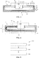
Figure 1 is a schematic cross-section of a lamp including a lamp component according to a first embodiment; -
Figure 2 is a schematic cross-section of the lamp offigure 1 illustrating various light paths when the LED light source emits light; -
Figure 3 is a schematic cross-section of a lamp including a lamp component according to a second embodiment; -
Figure 4 is a schematic a schematic cross-section of the lamp offigure 3 illustrating various light paths when the LED light source emits light; and -
Figure 5 is a sequence diagram illustrating a manufacturing method for manufacturing a lamp component according to an embodiment. - Exemplary embodiments will now be described with reference to the exemplary drawings, in which like reference signs refer to like parts or features. The described embodiments, aspects and drawings shall not be used to limit the scope or construction of the appended claims.
-
Figures 1 and 2 depict alamp component 1 for forming alamp 101 which has a large emission angle of about 270 degrees so as to provide ambient light in a room.Lamp component 1 has asource region 2, alight output surface 4, alight orienting element 6 and ahousing 8. -
Source region 2 is configured to receive aLED light source 10.Source region 2 receives aLED support 12, which supports LEDlight source 10.LED support 12 may be an extruded part.LED support 12 may include a supportingplate 13.LED light source 10 may be arranged insource region 2 such thatlamp 101 has a large emission angle of about 270 degrees. -
Light output surface 4 is configured to output light out oflamp component 1. Whenlamp 101 is installed for example on a non-illustrated ceiling of a room,light output surface 4 may be the lowest surface oflamp component 1.Lamp 101 may further include a non-illustrated fastening member configured to fasten the lamp to the ceiling of the room. - As illustrated on
figure 2 , whenlamp component 1 andlamp 101 are in operation, the light exiting fromlamp 101 may illuminate a non-illustrated room. All the lines that are present onfigure 2 but not onfigure 1 represent various light paths from a computational simulation of a state wherelamp 101 is in service andLED light source 10 is switched on. -
Light orienting element 6 is configured to receive light fromsource region 2, hence fromLED light source 10 whenlamp component 1 is assembled intolamp 101. Further,light orienting element 6 is configured to orient the received light withinlamp component 1 and towards thelight output surface 4, as will be hereafter detailed in relation tofigure 2 .Light orienting element 6 is herein comprised of a translucent reflector. -
Housing 8 is configured to define the position oflight orienting element 6 with respect to sourceregion 2.Housing 8 helps to properly positionlight orienting element 6 with respect to sourceregion 2. In the example offigures 1 and 2 ,housing 8 has twohousing sidewalls 14, which are configured to let incident light pass through them. - Further,
housing 8 has ahousing front wall 18. Housingfront wall 18 defineslight output surface 4. Housingfront wall 18 is herein one-piece with bothhousing sidewalls 14.Light orienting element 6 is located insidehousing 8.Housing 8 also surrounds, hence protects, the other parts oflamp 101, in particularlight orienting element 6. -
Light orienting element 6 is configured to deflect a fraction, e.g. a major fraction, i.e. more than 50%, of the light received fromsource region 2 towardslight output surface 4 so as to produce direct light 1.1. Further,light orienting element 6 is configured to refract a fraction, e.g. a minor fraction, i.e. less than 50%, of the light received fromsource region 2 towards bothhousing sidewalls 14 so as to produce indirect light 1.2. - For example, the ratio of the direct light onto the indirect light may be about 70/30. On
figure 2 , direct light is represented by light rays 1.1, whereas indirect light is represented by light rays 1.2. Direct light is the sum of the light rays that fall upon the target to be lit, say the floor of the room, without being previously reflected or diffracted by another surface in the room, say the ceiling or a wall. Conversely, indirect light is the sum of the light rays that reach the target to be lit only after having been reflected or diffracted at least once by another surface in the room. -
Light orienting element 6 is formed by a first extruded part, which extends in an extrusion direction X. Likewise,housing 8 is formed by a second extruded part, which extends in extrusion direction X. In the example offigures 1 and 2 , the first extruded part and the second extruded part, respectivelylight orienting element 6 andhousing 8, are formed by a co-extruded part, which extends in extrusion direction X. Thus,light orienting element 6 may be made integral withhousing 8 without requiring any joining means. Being formed by respective first and second extruded parts,light orienting element 6 andhousing 8 are not formed by molded parts. So,light orienting element 6 andhousing 8 may be free of any usual molding mark, for example a plane joint or a mold seam. -
Lamp component 1 andlamp 101 are symmetric about a plane defined by extrusion direction X and by a symmetry direction Y that is orthogonal to extrusion direction X. Accordingly,source region 2,light output surface 4,light orienting element 6,housing 8,LED light source 10 andLED support 12 are also symmetric about plane X-Y.Lamp component 1 may be sized at any desired length along extrusion direction X, the desired length depending on the intended use oflamp 101. - Housing sidewalls 14 respectively comprise
elongate prisms 15 that extend in extrusion direction X.Elongate prisms 15 are located on a respective inner face ofhousing sidewalls 14, hence ofhousing 8.Elongate prisms 15 are one-piece with the extruded part that formshousing 8. -
Elongate prisms 15 may help deflecting upwards or downwards the flat light rays that arrive ontohousing sidewalls 14 under a 0-degree angle with respect to the ceiling of the room. -
Light orienting element 6 andhousing 8 are made of two different materials.Light orienting element 6 may be made of a light-diffusing material, for example of polycarbonate (PC), a polymethyl-methacrylate (PMMA) and a polyamide (PA), the light-diffusing material may advantageously comprise a diffusing component. The diffusing component may for example be the component sold under the trademark Diffusor Pearl®.Light orienting element 6 may deflect a significant fraction of the incident light towardslight output surface 4.Housing 8 may be transparent and made for example of PMMA. -
Light orienting element 6 fulfils the function of a translucent reflector.Light orienting element 6 further has areflection layer 20 that is arranged to deflect a fraction of the light towards thelight output surface 4, as illustrated in particular infigure 2 .Reflection layer 20 is a layer of the first extruded part, i.e. oflight orienting element 6. Asreflection layer 20 helps reduce the light scattered in the room, thus enhancing the UGR value and a L65°-value oflamp 101. -
Light orienting element 6 comprises twolateral portions 22, which are arranged betweensource region 2 andlight output surface 4.Lateral portions 22 are arranged to generally diverge from each other towardslight output surface 4.Lateral portions 22 extend parallel to extrusion direction X. Each one oflateral portions 22 has a flat, planar shape, thus forming a lateral wall oflight orienting element 6. Each one oflateral portions 22 may have a thickness ranging from 1 mm to 4 mm_. -
Light orienting element 6 further comprises a linkingpart 26, which is arranged to linklateral portions 22 to each other. Linkingpart 26 is one-piece withlateral portions 22. Linkingpart 26 generally has a flat rounded shape that is concave with respect to sourceregion 2, i.e. that is bulging towardssource region 2. - Linking
part 26 helps to increase the proportion of indirect light as it deflects a part of the incident light, in particular via the portions of linkingpart 26 that connect tolateral portions 22, as illustrated onfigure 2 . Linkingpart 26 helps enhance the uniformity of the light distribution in the room. - Further,
light orienting element 6 comprises twoupstream portions 30.Upstream portions 30 extend in extrusion direction X and on both sides ofsource region 2. Eachupstream portion 30 has the general shape of a prism, which is configured to deflect light away fromlight output surface 4, as illustrated onfigure 2 .Upstream portions 30 are respectively one-piece withlateral portions 22. - Each
upstream portion 30 may help deflect upwards or downwards the incident light rays that arrive ontolight orienting element 6 under about a 0-degree angle with respect e.g. to the ceiling of the room. Such 0-degree or flat light rays are for example represented onfigure 2 by the uppermost light lines emitted byLED light source 10. - Each
upstream portion 30 contributes to the production of indirect light and to the enhancement of the uniformity of the light distribution of the light coming from the side regions of lamp 101 (right and left-hand sides onfigures 1 and 2 ). - Besides,
lamp component 1 further comprises anoutput device 36 that is arranged between light orientingelement 6 andlight output surface 4.Output device 36 is configured to scatter light exiting fromlamp component 1.Output device 36 includes a plate equipped with prisms configured for scattering incident light. -
Figures 3 and 4 illustrate a second embodiment of alamp component 1 and of alamp 101. Inasmuch aslamp component 1 andlamp 101 offigures 3 and 4 are respectively similar tolamp component 1 andlamp 101 offigures 1 and 2 , the afore-detailed description may be applied tolamp component 1 andlamp 101 offigures 3 and 4 , but for the hereinafter mentioned noticeable differences. An element oflamp component 1 andlamp 101 offigures 3 and 4 having a structure or function identical to an element oflamp component 1 andlamp 101 offigures 1 and 2 is given the same reference sign. - As illustrated on
figure 4 , whenlamp component 1 andlamp 101 are in operation, the light output fromlamp 101 may emit light towards a non-illustrated room. All the lines that are present onfigure 4 but not onfigure 3 represent various light paths from a computational simulation of a state wherelamp 101 is in service and switched on. - Like
lamp component 1 offigures 1 and 2 ,lamp component 1 offigures 3 and 4 may comprise asource region 2, alight output surface 4, ahousing 8 withhousing sidewalls 14 andelongate prisms 15. Likelamp component 1 andlamp 1 offigures 1 and 2 ,lamp component 1 andlamp 1 offigures 3 and 4 are symmetric about a plane X-Y defined by extrusion direction X and by a symmetry direction Y that is orthogonal to extrusion direction X. Like inlamp component 1 offigures 1 and 2 ,light orienting element 6 offigures 3 and 4 is configured to produce direct light 1.1 and indirect light 1.2. -
Lamp 101 offigures 3 and 4 differs fromlamp 101 offigures 1 and 2 in thatlamp 101 offigures 3 and 4 comprises twoLED light sources 10.LED light sources 10 are mounted on respective LED supports 12. Accordingly,lamp component 1 comprises twosource regions 2, which are configured to receive respectiveLED light sources 10.Light orienting element 6 is arranged to receive light from bothsource regions 2 and to orient the received light withinlamp component 1 and towards thelight output surface 4. -
Lamp 101 offigures 3 and 4 further differs fromlamp 101 offigures 1 and 2 in that thelight orienting element 6 offigures 3 and 4 is herein comprised of a light guide. The light rays may thus enter the light guide, then be reflected several times inside the light guide, and be eventually conveyed through thelight output surface 4. - On
figure 2 , only one ofLED light sources 10 is switched on (left-hand side). However, both LEDlight sources 10 may be switched on simultaneously. In an alternative embodiment,lamp 101 may comprise only oneLED light source 10, in whichcase lamp 101 is not symmetric. -
Lamp component 1 offigures 3 and 4 further differs fromlamp component 1 offigures 1 and 2 in thatlamp component 1 offigures 3 and 4 comprises alight orienting element 6 that is shaped differently fromlight orienting element 6 offigures 1 and 2 . Indeed,light orienting element 6 comprises anupstream portion 40, adownstream portion 42 and acurved portion 44. -
Curved portion 44 is configured to connectupstream portion 40 todownstream portion 42.curved portion 44 generally has a U-shaped cross-section.Upstream portion 40 anddownstream portion 42 generally have a flat cross-section.Upstream portion 40 has planar faces. - A downstream face of
downstream portion 42 is ripples in order to output light via several ribs orgrooves 46. The width of theribs 46 increases progressively as a function of the distance of theribs 46 to sourceregion 2, herein also to symmetry direction Y. In the example offigures 3 and 4 , the width of the ribs increases continuously, i.e. at each new rib, as a function of the distance of the rib to sourceregion 2. - The
ribs 46 define a series of prisms that deflect light and output it out of downstream face of thedownstream portion 44. Sinceribs 46 have an increasing width, the light can be evenly distributed over the downstream face ofdownstream portion 44. The width of arib 46 may be measured alongdownstream portion 44 in a plane orthogonal to the extrusion direction X (e.g. plane offigure 3 ).Lamp 101 has a flat design while emitting light with a large emission angle of 270-360 degrees. - Besides,
lamp component 1 offigures 3 and 4 differs fromlamp component 1 offigures 1 and 2 in thatreflection layer 20 is separate from and attached to light orientingelement 6, in particular todownstream portion 42.Reflection layer 20 may be formed by a sheet having reflecting properties. -
Lamp component 1 offigures 3 and 4 differs fromlamp component 1 offigures 1 and 2 in thatlamp component 1 offigures 3 and 4 further comprises aside mask 50.Side mask 50 is opaque and extends betweencurved portion 44 andhousing sidewall 14 in order to prevent most of the light output from a connection region betweenupstream portion 40 andcurved portion 44 from travelling tohousing sidewall 14. - Further,
lamp component 1 offigures 3 and 4 differs fromlamp component 1 offigures 1 and 2 in thathousing 8 comprises anupper wall 52, which is separate from theadjacent housing sidewall 14, and which is configured to reflect most or all of the incident light.Upper wall 52 is configured to prevent light from passing therethrough. Only a few light rays passupper walls 52 onfigure 4 , whereas much more light rays pass the upper walls ofhousing 8 onfigure 2 . - As represented on
figure 4 , a large fraction of light emitted byLED light source 10 is conveyed downstream thelight orienting element 6 and then output throughlight output surface 4, thus producing direct light. Part of the light emitted byLED light source 10 is refracted inlight orienting element 6 and exits fromlamp component 1 viahousing sidewalls 14, thus producing indirect light. -
Figure 5 represents amanufacturing method 501 according to an embodiment, formanufacturing lamp component 1 for forminglamp 101. Themanufacturing method 501 comprises at least: - box 502: forming
light orienting element 6 by extruding a first extruded part extending in extrusion direction X,light orienting element 6 being configured: i) to receive light fromsource region 2 oflamp component 1 and ii) to orient the received light withinlamp component 1 and towards thelight output surface 4,source region 2 being configured to receive one or more LED light source(s) 10. - box 504: forming
housing 8 by extruding a second extruded part extending in extrusion direction X, the first extruded part and the second extruded part being advantageously formed by a co-extruded part,housing 8 being configured to define the position oflight orienting element 6 with respect to sourceregion 2,housing 8 having at least onehousing sidewall 14 configured to let light pass through it, and - box 506: implementing
light output surface 4 configured to output light out of thelamp component 1,light orienting element 6 being further configured i) to deflect a fraction of the light towardslight output surface 4 so as to produce direct light, and ii) to refract a fraction of the light towards the at least onehousing sidewall 14 so as to produce indirect light. -
Lamp component 1 may be manufactured to be sized at any desired length along extrusion direction X, the desired length depending on the intended use oflamp 101. - Although the present invention has been described above in relation to the exemplary drawings, the present invention is not limited to the embodiments described above and illustrated in the exemplary drawings. Many changes and alternatives may be made by the skilled person within the scope of the present invention as defined in the appended claims.
wherein the light orienting element is formed by a first extruded part extending in an extrusion direction, and
wherein the housing is formed by a second extruded part extending in the extrusion direction.
Claims (14)
- A lamp component (1), for forming a lamp (101) so as to provide ambient light in a room, the lamp component (1) having at least:- a source region (2) configured to receive at least one LED light source (10),- a light output surface (4) configured to output light out of the lamp component (1),- a light orienting element (6) configured to receive light from the source region (2) and to orient the received light towards the light output surface (4), and- a housing (8) configured to define the position of the light orienting element (6) with respect to the source region (2), the housing (8) having at least one housing sidewall (14) configured to let light pass through it,wherein the light orienting element (6) is configured i) to deflect a fraction of the light towards the light output surface (4) so as to produce direct light, and ii) to refract a fraction of the light towards the at least one housing sidewall (14) so as to produce indirect light,
wherein the light orienting element (6) is formed by a first extruded part extending in an extrusion direction (X), and
wherein the housing (8) is formed by a second extruded part extending in the extrusion direction (X). - The lamp component (1) according to claim 1, wherein the first extruded part and the second extruded part are formed by a co-extruded part.
- The lamp component (1) according to any one of the preceding claims, wherein the light orienting element (6) has a reflection layer (20) that is arranged to deflect a fraction of the light towards the light output surface (4), the reflection layer(20) being either a layer of the first extruded part or a separate layer attached to the first extruded part.
- The lamp component (1) according to any one of the preceding claims, wherein the light orienting element (6) is made of a light-diffusing material, which is advantageously selected in the group consisting of: a polycarbonate (PC), a polymethyl-methacrylate (PMMA) and a polyamide (PA), the light-diffusing material advantageously comprising a diffusing component.
- The lamp component (1) according to any one of the preceding claims, wherein the light orienting element (6) is configured i) to deflect a major fraction of the light towards the light output surface (4), and ii) to refract a minor fraction of the light towards the at least one housing sidewall (14), such that the ratio of the direct light onto the indirect light ranges from 60/40 to 80/20, advantageously from 68/32 to 72/28.
- The lamp component (1) according to any one of the preceding claims, wherein the light orienting element (6) comprises two lateral portions (22) arranged between the source region (2) and the light output surface (4), the lateral portions (22) being arranged to generally diverge from each other towards the light output surface (4).
- The lamp component (1) according to claim 6, wherein at least one lateral portion (22) extends parallel to the extrusion direction (X), at least one lateral portion (22) generally having a flat planar shape.
- The lamp component (1) according to claim 6 or 7, wherein the light orienting element (6) further comprises a linking part (26), which is arranged to link the lateral portions (22) with each other, the linking part (26) being advantageously integral, and preferably one-piece, with the lateral portions (22).
- The lamp component (1) according to claim 8, wherein the linking part (26) generally has a flat rounded shape in cross section, the flat rounded shape being advantageously concave with respect to the source region (2).
- The lamp component (1) according to any one of the preceding claims, wherein the light orienting element (6) further comprises at least two upstream portions (30), the upstream portions (30) extending in the extrusion direction (X) and on both sides of the source region (2), each upstream portion (30) having the general shape of a prism configured to deflect light away from the light output surface (4).
- The lamp component (1) according to any one of the preceding claims, wherein the housing (8) further has a housing front wall (18), the housing front wall (18) defining the light output surface (4), the housing front wall (18) being one-piece with the at least one housing sidewall (14).
- The lamp component (1) according to any one of the preceding claims, wherein the housing (8) is made of a transparent material, which is advantageously selected in the group consisting of: a polycarbonate (PC), a polymethyl-methacrylate (PMMA) and a polyamide (PA).
- A lamp (101), for example a luminaire, for providing ambient light in a room, the lamp (101) comprising at least one lamp component (1) according to any one of the preceding claims, the lamp (101) further comprising at least one LED light source (10) arranged in the source region (2) such that the lamp (101) has an emission angle of between 270 and 360 degrees.
- A manufacturing method (501), for manufacturing a lamp component (1) for forming a lamp (101) having an emission angle of between 270 and 360 degrees so as to provide ambient light in a room, wherein the manufacturing method (501) comprises at least:- forming (502) a light orienting element (6) by extruding a first extruded part extending in an extrusion direction (X),
the source region (2) being configured to receive at least one LED light source (10), the light orienting element (6) being configured: i) to receive light from a source region (2) of the lamp component (1) and ii) to orient the received light towards the light output surface (4),- forming (504) a housing (8) by extruding a second extruded part extending in the extrusion direction (X), the first extruded part and the second extruded part being advantageously formed by a co-extruded part,
the housing (8) being configured to define the position of the light orienting element (6) with respect to the source region (2), the housing (8) having at least one housing sidewall (14) configured to let light pass through it, and- implementing (506) a light output surface (4) configured to output light out of the lamp component (1),
the light orienting element (6) being further configured i) to deflect a fraction of the light towards the light output surface (4) so as to produce direct light, and ii) to refract a fraction of the light towards the at least one housing sidewall (14) so as to produce indirect light.
Priority Applications (6)
| Application Number | Priority Date | Filing Date | Title |
|---|---|---|---|
| EP18195636.8A EP3626425B1 (en) | 2018-09-20 | 2018-09-20 | Lamp component for forming a lamp having a large emission angle, lamp and method for manufacturing such a lamp component |
| GB1900959.6A GB2577352B (en) | 2018-09-20 | 2019-01-18 | Lamp component forming a lamp having a large emission angle, lamp and method for manufacturing such a lamp component |
| US17/268,545 US11391443B2 (en) | 2018-09-20 | 2019-09-05 | LED lamp component having reflective/refractive element within translucent housing |
| EP19762400.0A EP3837102B1 (en) | 2018-09-20 | 2019-09-05 | Lamp component for forming a lamp having a large emission angle, lamp and method for manufacturing such a lamp component |
| CN201980052148.0A CN112533747B (en) | 2018-09-20 | 2019-09-05 | Lamp component forming a lamp with a large emission angle, lamp and method of manufacturing such a lamp component |
| PCT/EP2019/073646 WO2020057985A1 (en) | 2018-09-20 | 2019-09-05 | Lamp component forming a lamp having a large emission angle, lamp and method for manufacturing such a lamp component |
Applications Claiming Priority (1)
| Application Number | Priority Date | Filing Date | Title |
|---|---|---|---|
| EP18195636.8A EP3626425B1 (en) | 2018-09-20 | 2018-09-20 | Lamp component for forming a lamp having a large emission angle, lamp and method for manufacturing such a lamp component |
Publications (2)
| Publication Number | Publication Date |
|---|---|
| EP3626425A1 true EP3626425A1 (en) | 2020-03-25 |
| EP3626425B1 EP3626425B1 (en) | 2023-01-18 |
Family
ID=63667740
Family Applications (2)
| Application Number | Title | Priority Date | Filing Date |
|---|---|---|---|
| EP18195636.8A Active EP3626425B1 (en) | 2018-09-20 | 2018-09-20 | Lamp component for forming a lamp having a large emission angle, lamp and method for manufacturing such a lamp component |
| EP19762400.0A Active EP3837102B1 (en) | 2018-09-20 | 2019-09-05 | Lamp component for forming a lamp having a large emission angle, lamp and method for manufacturing such a lamp component |
Family Applications After (1)
| Application Number | Title | Priority Date | Filing Date |
|---|---|---|---|
| EP19762400.0A Active EP3837102B1 (en) | 2018-09-20 | 2019-09-05 | Lamp component for forming a lamp having a large emission angle, lamp and method for manufacturing such a lamp component |
Country Status (5)
| Country | Link |
|---|---|
| US (1) | US11391443B2 (en) |
| EP (2) | EP3626425B1 (en) |
| CN (1) | CN112533747B (en) |
| GB (1) | GB2577352B (en) |
| WO (1) | WO2020057985A1 (en) |
Families Citing this family (7)
| Publication number | Priority date | Publication date | Assignee | Title |
|---|---|---|---|---|
| US11500461B2 (en) | 2019-11-01 | 2022-11-15 | Evolution Optiks Limited | Light field vision-based testing device, system and method |
| DE202019105265U1 (en) * | 2019-09-24 | 2021-01-04 | Zumtobel Lighting Gmbh | Luminaire with area for flat light emission |
| US11754255B2 (en) * | 2019-12-20 | 2023-09-12 | Lumileds Llc | Curved light-guide optics for LED street lighting |
| US11781732B2 (en) * | 2021-12-22 | 2023-10-10 | Ideal Industries Lighting Llc | Lighting fixture with lens assembly for reduced glare |
| CN117072921A (en) * | 2023-09-27 | 2023-11-17 | 厦门普为光电科技有限公司 | Lamps with seamless splicing function |
| IT202300024543A1 (en) * | 2023-11-20 | 2025-05-20 | Ivela S R L | LIGHTING DEVICE AND PROCEDURE FOR MAKING IT |
| ES1320891Y (en) * | 2024-10-17 | 2025-09-29 | Antares Iluminacion S A U | Ambient light emitting lighting device |
Citations (3)
| Publication number | Priority date | Publication date | Assignee | Title |
|---|---|---|---|---|
| US20100321921A1 (en) * | 2009-06-23 | 2010-12-23 | Altair Engineering, Inc. | Led lamp with a wavelength converting layer |
| US20150022999A1 (en) * | 2012-03-30 | 2015-01-22 | Samsung Electronics Co., Ltd. | Lighting device and method for manufacturing the same |
| WO2016102512A1 (en) * | 2014-12-22 | 2016-06-30 | Nualight Limited | A refrigerator led illuminator with tubular housing and internal lens |
Family Cites Families (28)
| Publication number | Priority date | Publication date | Assignee | Title |
|---|---|---|---|---|
| US1472050A (en) * | 1921-09-17 | 1923-10-30 | Augustus D Curtis | Lighting fixture |
| US2436635A (en) * | 1944-02-24 | 1948-02-24 | Doane Products Corp | Luminaire |
| US2499580A (en) * | 1948-07-09 | 1950-03-07 | Lightolier Inc | Reflector bowl |
| US2675466A (en) * | 1951-01-09 | 1954-04-13 | Frederick C Baker | Ceiling lighting fixture |
| CH669830A5 (en) * | 1986-03-17 | 1989-04-14 | Peter A Balla | |
| US4974137A (en) * | 1990-04-11 | 1990-11-27 | Lam Lighting Systems | High intensity indirect lighting fixture |
| JPH0677101U (en) * | 1993-04-02 | 1994-10-28 | スタンレー電気株式会社 | Vehicle lighting |
| US5988836A (en) * | 1996-07-31 | 1999-11-23 | Swarens; Ralph W. | Recessed indirect fluorescent light fixture with flexible reflector |
| NL1008523C2 (en) * | 1998-03-06 | 1999-09-07 | Spanninga Metaal | Tail light. |
| US6161939A (en) * | 1999-05-05 | 2000-12-19 | Semperlux Ag | Interior lighting fixture |
| US8002446B1 (en) * | 2008-06-09 | 2011-08-23 | Koninklijke Philips Electronics N.V. | Virtual direct and indirect suspended lighting fixture |
| CN101655213A (en) * | 2008-08-21 | 2010-02-24 | 鸿富锦精密工业(深圳)有限公司 | Light-emitting diode light source module |
| CN201487799U (en) * | 2009-09-04 | 2010-05-26 | 伍铁军 | LED strip screen wall lamp |
| CN102128420A (en) * | 2010-01-18 | 2011-07-20 | 奥斯兰姆有限公司 | Lamp shells and manufacturing method thereof and lamp with lamp shells |
| CN101881387A (en) * | 2010-06-10 | 2010-11-10 | 鸿富锦精密工业(深圳)有限公司 | LED fluorescent lamp |
| US8602604B2 (en) * | 2010-10-14 | 2013-12-10 | Lunera Lighting, Inc. | Extruded wide angle lens for use with a LED light source |
| US9494293B2 (en) * | 2010-12-06 | 2016-11-15 | Cree, Inc. | Troffer-style optical assembly |
| US9581312B2 (en) * | 2010-12-06 | 2017-02-28 | Cree, Inc. | LED light fixtures having elongated prismatic lenses |
| CN102072428B (en) * | 2010-12-20 | 2013-05-08 | 鸿富锦精密工业(深圳)有限公司 | Light emitting diode (LED) daylight lamp |
| JP5335945B2 (en) * | 2011-12-09 | 2013-11-06 | 株式会社エンプラス | Luminous flux control member and lighting device |
| JP6250660B2 (en) * | 2012-06-28 | 2017-12-20 | インテマティックス・コーポレーションIntematix Corporation | Lamp and optical component manufacturing method |
| DE102012109265B4 (en) * | 2012-09-28 | 2016-02-25 | Elkamet Kunststofftechnik Gmbh | Lamp and a component for it |
| TWI521172B (en) * | 2014-01-17 | 2016-02-11 | 雷笛揚照明股份有限公司 | Lamp |
| CN106062471B (en) * | 2014-02-28 | 2018-06-05 | 三菱电机株式会社 | Ligthing paraphernalia, light source cover, light control member and light source unit |
| US20160076706A1 (en) * | 2014-09-17 | 2016-03-17 | Ge Lighting Solutions, Llc. | Method and system for led lamp incorporating internal optics for specific light distribution |
| US20180149320A1 (en) * | 2015-04-10 | 2018-05-31 | Abram Corporation | Light-emitting diode type lighting device |
| CN207527348U (en) * | 2017-04-21 | 2018-06-22 | 漳州立达信光电子科技有限公司 | A LED light bar |
| CN110529823A (en) * | 2019-06-19 | 2019-12-03 | 赛尔富电子有限公司 | A kind of optical element and the headlamp with the optical element |
-
2018
- 2018-09-20 EP EP18195636.8A patent/EP3626425B1/en active Active
-
2019
- 2019-01-18 GB GB1900959.6A patent/GB2577352B/en active Active
- 2019-09-05 US US17/268,545 patent/US11391443B2/en active Active
- 2019-09-05 WO PCT/EP2019/073646 patent/WO2020057985A1/en not_active Ceased
- 2019-09-05 CN CN201980052148.0A patent/CN112533747B/en active Active
- 2019-09-05 EP EP19762400.0A patent/EP3837102B1/en active Active
Patent Citations (3)
| Publication number | Priority date | Publication date | Assignee | Title |
|---|---|---|---|---|
| US20100321921A1 (en) * | 2009-06-23 | 2010-12-23 | Altair Engineering, Inc. | Led lamp with a wavelength converting layer |
| US20150022999A1 (en) * | 2012-03-30 | 2015-01-22 | Samsung Electronics Co., Ltd. | Lighting device and method for manufacturing the same |
| WO2016102512A1 (en) * | 2014-12-22 | 2016-06-30 | Nualight Limited | A refrigerator led illuminator with tubular housing and internal lens |
Also Published As
| Publication number | Publication date |
|---|---|
| GB201900959D0 (en) | 2019-03-13 |
| EP3837102A1 (en) | 2021-06-23 |
| GB2577352B (en) | 2023-01-11 |
| GB2577352A (en) | 2020-03-25 |
| CN112533747A (en) | 2021-03-19 |
| US20210332968A1 (en) | 2021-10-28 |
| CN112533747B (en) | 2022-11-01 |
| US11391443B2 (en) | 2022-07-19 |
| EP3626425B1 (en) | 2023-01-18 |
| WO2020057985A1 (en) | 2020-03-26 |
| EP3837102B1 (en) | 2025-01-22 |
Similar Documents
| Publication | Publication Date | Title |
|---|---|---|
| EP3626425B1 (en) | Lamp component for forming a lamp having a large emission angle, lamp and method for manufacturing such a lamp component | |
| US10378722B2 (en) | Lighting system, in particular for a motor vehicle lighting member, comprising integrated LEDs | |
| JP2020024867A (en) | Vehicular lighting fixture | |
| KR20150137959A (en) | Secondary optical element and light source module | |
| US20150285450A1 (en) | Lighting device for indirect illumination | |
| JP2012134035A (en) | Lighting device | |
| KR20150056401A (en) | Optical member and lighting device using same | |
| CN108131595B (en) | Lamp fitting | |
| CN117063012A (en) | Light emitting device and vehicle | |
| CN107076376B (en) | Luminaires especially for road lighting | |
| JP2023160869A (en) | lighting equipment | |
| EP3278013B1 (en) | Lighting system using a lightguide. | |
| JP2014060040A (en) | Vehicular lighting fixture | |
| US12404989B2 (en) | Optics for luminaires | |
| JP3209438U (en) | Lighting device | |
| CN111373194B (en) | Lighting device | |
| CN107620886A (en) | Lighting device | |
| WO2022264764A1 (en) | Light guide plate and light emitting device using same | |
| JP2015130250A (en) | Lighting device | |
| JP2025086065A (en) | Vehicle lighting fixtures | |
| CN120062577A (en) | Light guide element, car lamp and vehicle |
Legal Events
| Date | Code | Title | Description |
|---|---|---|---|
| PUAI | Public reference made under article 153(3) epc to a published international application that has entered the european phase |
Free format text: ORIGINAL CODE: 0009012 |
|
| STAA | Information on the status of an ep patent application or granted ep patent |
Free format text: STATUS: THE APPLICATION HAS BEEN PUBLISHED |
|
| AK | Designated contracting states |
Kind code of ref document: A1 Designated state(s): AL AT BE BG CH CY CZ DE DK EE ES FI FR GB GR HR HU IE IS IT LI LT LU LV MC MK MT NL NO PL PT RO RS SE SI SK SM TR |
|
| AX | Request for extension of the european patent |
Extension state: BA ME |
|
| STAA | Information on the status of an ep patent application or granted ep patent |
Free format text: STATUS: REQUEST FOR EXAMINATION WAS MADE |
|
| 17P | Request for examination filed |
Effective date: 20200817 |
|
| RBV | Designated contracting states (corrected) |
Designated state(s): AL AT BE BG CH CY CZ DE DK EE ES FI FR GB GR HR HU IE IS IT LI LT LU LV MC MK MT NL NO PL PT RO RS SE SI SK SM TR |
|
| STAA | Information on the status of an ep patent application or granted ep patent |
Free format text: STATUS: EXAMINATION IS IN PROGRESS |
|
| 17Q | First examination report despatched |
Effective date: 20201202 |
|
| GRAP | Despatch of communication of intention to grant a patent |
Free format text: ORIGINAL CODE: EPIDOSNIGR1 |
|
| STAA | Information on the status of an ep patent application or granted ep patent |
Free format text: STATUS: GRANT OF PATENT IS INTENDED |
|
| INTG | Intention to grant announced |
Effective date: 20220720 |
|
| GRAS | Grant fee paid |
Free format text: ORIGINAL CODE: EPIDOSNIGR3 |
|
| GRAA | (expected) grant |
Free format text: ORIGINAL CODE: 0009210 |
|
| STAA | Information on the status of an ep patent application or granted ep patent |
Free format text: STATUS: THE PATENT HAS BEEN GRANTED |
|
| AK | Designated contracting states |
Kind code of ref document: B1 Designated state(s): AL AT BE BG CH CY CZ DE DK EE ES FI FR GR HR HU IE IS IT LI LT LU LV MC MK MT NL NO PL PT RO RS SE SI SK SM TR |
|
| RBV | Designated contracting states (corrected) |
Designated state(s): AL AT BE BG CH CY CZ DE DK EE ES FI FR GR HR HU IE IS IT LI LT LU LV MC MK MT NL NO PL PT RO RS SE SI SK SM TR |
|
| REG | Reference to a national code |
Ref country code: DE Ref legal event code: R096 Ref document number: 602018045469 Country of ref document: DE |
|
| REG | Reference to a national code |
Ref country code: CH Ref legal event code: EP |
|
| REG | Reference to a national code |
Ref country code: AT Ref legal event code: REF Ref document number: 1544449 Country of ref document: AT Kind code of ref document: T Effective date: 20230215 Ref country code: IE Ref legal event code: FG4D |
|
| REG | Reference to a national code |
Ref country code: LT Ref legal event code: MG9D |
|
| REG | Reference to a national code |
Ref country code: NL Ref legal event code: MP Effective date: 20230118 |
|
| PG25 | Lapsed in a contracting state [announced via postgrant information from national office to epo] |
Ref country code: NL Free format text: LAPSE BECAUSE OF FAILURE TO SUBMIT A TRANSLATION OF THE DESCRIPTION OR TO PAY THE FEE WITHIN THE PRESCRIBED TIME-LIMIT Effective date: 20230118 |
|
| P01 | Opt-out of the competence of the unified patent court (upc) registered |
Effective date: 20230530 |
|
| PG25 | Lapsed in a contracting state [announced via postgrant information from national office to epo] |
Ref country code: RS Free format text: LAPSE BECAUSE OF FAILURE TO SUBMIT A TRANSLATION OF THE DESCRIPTION OR TO PAY THE FEE WITHIN THE PRESCRIBED TIME-LIMIT Effective date: 20230118 Ref country code: PT Free format text: LAPSE BECAUSE OF FAILURE TO SUBMIT A TRANSLATION OF THE DESCRIPTION OR TO PAY THE FEE WITHIN THE PRESCRIBED TIME-LIMIT Effective date: 20230518 Ref country code: NO Free format text: LAPSE BECAUSE OF FAILURE TO SUBMIT A TRANSLATION OF THE DESCRIPTION OR TO PAY THE FEE WITHIN THE PRESCRIBED TIME-LIMIT Effective date: 20230418 Ref country code: LV Free format text: LAPSE BECAUSE OF FAILURE TO SUBMIT A TRANSLATION OF THE DESCRIPTION OR TO PAY THE FEE WITHIN THE PRESCRIBED TIME-LIMIT Effective date: 20230118 Ref country code: LT Free format text: LAPSE BECAUSE OF FAILURE TO SUBMIT A TRANSLATION OF THE DESCRIPTION OR TO PAY THE FEE WITHIN THE PRESCRIBED TIME-LIMIT Effective date: 20230118 Ref country code: HR Free format text: LAPSE BECAUSE OF FAILURE TO SUBMIT A TRANSLATION OF THE DESCRIPTION OR TO PAY THE FEE WITHIN THE PRESCRIBED TIME-LIMIT Effective date: 20230118 Ref country code: ES Free format text: LAPSE BECAUSE OF FAILURE TO SUBMIT A TRANSLATION OF THE DESCRIPTION OR TO PAY THE FEE WITHIN THE PRESCRIBED TIME-LIMIT Effective date: 20230118 |
|
| PG25 | Lapsed in a contracting state [announced via postgrant information from national office to epo] |
Ref country code: SE Free format text: LAPSE BECAUSE OF FAILURE TO SUBMIT A TRANSLATION OF THE DESCRIPTION OR TO PAY THE FEE WITHIN THE PRESCRIBED TIME-LIMIT Effective date: 20230118 Ref country code: PL Free format text: LAPSE BECAUSE OF FAILURE TO SUBMIT A TRANSLATION OF THE DESCRIPTION OR TO PAY THE FEE WITHIN THE PRESCRIBED TIME-LIMIT Effective date: 20230118 Ref country code: IS Free format text: LAPSE BECAUSE OF FAILURE TO SUBMIT A TRANSLATION OF THE DESCRIPTION OR TO PAY THE FEE WITHIN THE PRESCRIBED TIME-LIMIT Effective date: 20230518 Ref country code: GR Free format text: LAPSE BECAUSE OF FAILURE TO SUBMIT A TRANSLATION OF THE DESCRIPTION OR TO PAY THE FEE WITHIN THE PRESCRIBED TIME-LIMIT Effective date: 20230419 Ref country code: FI Free format text: LAPSE BECAUSE OF FAILURE TO SUBMIT A TRANSLATION OF THE DESCRIPTION OR TO PAY THE FEE WITHIN THE PRESCRIBED TIME-LIMIT Effective date: 20230118 |
|
| REG | Reference to a national code |
Ref country code: DE Ref legal event code: R097 Ref document number: 602018045469 Country of ref document: DE |
|
| PG25 | Lapsed in a contracting state [announced via postgrant information from national office to epo] |
Ref country code: SM Free format text: LAPSE BECAUSE OF FAILURE TO SUBMIT A TRANSLATION OF THE DESCRIPTION OR TO PAY THE FEE WITHIN THE PRESCRIBED TIME-LIMIT Effective date: 20230118 Ref country code: RO Free format text: LAPSE BECAUSE OF FAILURE TO SUBMIT A TRANSLATION OF THE DESCRIPTION OR TO PAY THE FEE WITHIN THE PRESCRIBED TIME-LIMIT Effective date: 20230118 Ref country code: EE Free format text: LAPSE BECAUSE OF FAILURE TO SUBMIT A TRANSLATION OF THE DESCRIPTION OR TO PAY THE FEE WITHIN THE PRESCRIBED TIME-LIMIT Effective date: 20230118 Ref country code: DK Free format text: LAPSE BECAUSE OF FAILURE TO SUBMIT A TRANSLATION OF THE DESCRIPTION OR TO PAY THE FEE WITHIN THE PRESCRIBED TIME-LIMIT Effective date: 20230118 Ref country code: CZ Free format text: LAPSE BECAUSE OF FAILURE TO SUBMIT A TRANSLATION OF THE DESCRIPTION OR TO PAY THE FEE WITHIN THE PRESCRIBED TIME-LIMIT Effective date: 20230118 |
|
| PGFP | Annual fee paid to national office [announced via postgrant information from national office to epo] |
Ref country code: AT Payment date: 20230919 Year of fee payment: 6 |
|
| PLBE | No opposition filed within time limit |
Free format text: ORIGINAL CODE: 0009261 |
|
| STAA | Information on the status of an ep patent application or granted ep patent |
Free format text: STATUS: NO OPPOSITION FILED WITHIN TIME LIMIT |
|
| PG25 | Lapsed in a contracting state [announced via postgrant information from national office to epo] |
Ref country code: SK Free format text: LAPSE BECAUSE OF FAILURE TO SUBMIT A TRANSLATION OF THE DESCRIPTION OR TO PAY THE FEE WITHIN THE PRESCRIBED TIME-LIMIT Effective date: 20230118 |
|
| 26N | No opposition filed |
Effective date: 20231019 |
|
| PG25 | Lapsed in a contracting state [announced via postgrant information from national office to epo] |
Ref country code: SI Free format text: LAPSE BECAUSE OF FAILURE TO SUBMIT A TRANSLATION OF THE DESCRIPTION OR TO PAY THE FEE WITHIN THE PRESCRIBED TIME-LIMIT Effective date: 20230118 |
|
| PG25 | Lapsed in a contracting state [announced via postgrant information from national office to epo] |
Ref country code: LU Free format text: LAPSE BECAUSE OF NON-PAYMENT OF DUE FEES Effective date: 20230920 |
|
| REG | Reference to a national code |
Ref country code: BE Ref legal event code: MM Effective date: 20230930 |
|
| PG25 | Lapsed in a contracting state [announced via postgrant information from national office to epo] |
Ref country code: LU Free format text: LAPSE BECAUSE OF NON-PAYMENT OF DUE FEES Effective date: 20230920 Ref country code: IT Free format text: LAPSE BECAUSE OF FAILURE TO SUBMIT A TRANSLATION OF THE DESCRIPTION OR TO PAY THE FEE WITHIN THE PRESCRIBED TIME-LIMIT Effective date: 20230118 Ref country code: MC Free format text: LAPSE BECAUSE OF FAILURE TO SUBMIT A TRANSLATION OF THE DESCRIPTION OR TO PAY THE FEE WITHIN THE PRESCRIBED TIME-LIMIT Effective date: 20230118 |
|
| REG | Reference to a national code |
Ref country code: IE Ref legal event code: MM4A |
|
| PG25 | Lapsed in a contracting state [announced via postgrant information from national office to epo] |
Ref country code: IE Free format text: LAPSE BECAUSE OF NON-PAYMENT OF DUE FEES Effective date: 20230920 |
|
| REG | Reference to a national code |
Ref country code: AT Ref legal event code: UEP Ref document number: 1544449 Country of ref document: AT Kind code of ref document: T Effective date: 20230118 |
|
| PG25 | Lapsed in a contracting state [announced via postgrant information from national office to epo] |
Ref country code: IE Free format text: LAPSE BECAUSE OF NON-PAYMENT OF DUE FEES Effective date: 20230920 |
|
| PG25 | Lapsed in a contracting state [announced via postgrant information from national office to epo] |
Ref country code: BE Free format text: LAPSE BECAUSE OF NON-PAYMENT OF DUE FEES Effective date: 20230930 |
|
| PG25 | Lapsed in a contracting state [announced via postgrant information from national office to epo] |
Ref country code: BG Free format text: LAPSE BECAUSE OF FAILURE TO SUBMIT A TRANSLATION OF THE DESCRIPTION OR TO PAY THE FEE WITHIN THE PRESCRIBED TIME-LIMIT Effective date: 20230118 |
|
| PG25 | Lapsed in a contracting state [announced via postgrant information from national office to epo] |
Ref country code: BG Free format text: LAPSE BECAUSE OF FAILURE TO SUBMIT A TRANSLATION OF THE DESCRIPTION OR TO PAY THE FEE WITHIN THE PRESCRIBED TIME-LIMIT Effective date: 20230118 |
|
| REG | Reference to a national code |
Ref country code: AT Ref legal event code: MM01 Ref document number: 1544449 Country of ref document: AT Kind code of ref document: T Effective date: 20240920 |
|
| PG25 | Lapsed in a contracting state [announced via postgrant information from national office to epo] |
Ref country code: AT Free format text: LAPSE BECAUSE OF NON-PAYMENT OF DUE FEES Effective date: 20240920 |
|
| PG25 | Lapsed in a contracting state [announced via postgrant information from national office to epo] |
Ref country code: CY Free format text: LAPSE BECAUSE OF FAILURE TO SUBMIT A TRANSLATION OF THE DESCRIPTION OR TO PAY THE FEE WITHIN THE PRESCRIBED TIME-LIMIT; INVALID AB INITIO Effective date: 20180920 |
|
| PG25 | Lapsed in a contracting state [announced via postgrant information from national office to epo] |
Ref country code: HU Free format text: LAPSE BECAUSE OF FAILURE TO SUBMIT A TRANSLATION OF THE DESCRIPTION OR TO PAY THE FEE WITHIN THE PRESCRIBED TIME-LIMIT; INVALID AB INITIO Effective date: 20180920 |
|
| REG | Reference to a national code |
Ref country code: CH Ref legal event code: U11 Free format text: ST27 STATUS EVENT CODE: U-0-0-U10-U11 (AS PROVIDED BY THE NATIONAL OFFICE) Effective date: 20251001 |
|
| PGFP | Annual fee paid to national office [announced via postgrant information from national office to epo] |
Ref country code: DE Payment date: 20250926 Year of fee payment: 8 |
|
| PGFP | Annual fee paid to national office [announced via postgrant information from national office to epo] |
Ref country code: FR Payment date: 20250925 Year of fee payment: 8 |
|
| PG25 | Lapsed in a contracting state [announced via postgrant information from national office to epo] |
Ref country code: TR Free format text: LAPSE BECAUSE OF FAILURE TO SUBMIT A TRANSLATION OF THE DESCRIPTION OR TO PAY THE FEE WITHIN THE PRESCRIBED TIME-LIMIT Effective date: 20230118 |
|
| PGFP | Annual fee paid to national office [announced via postgrant information from national office to epo] |
Ref country code: CH Payment date: 20251001 Year of fee payment: 8 |