EP3626382A1 - Laser welding method and laser welding device - Google Patents
Laser welding method and laser welding device Download PDFInfo
- Publication number
- EP3626382A1 EP3626382A1 EP18801873.3A EP18801873A EP3626382A1 EP 3626382 A1 EP3626382 A1 EP 3626382A1 EP 18801873 A EP18801873 A EP 18801873A EP 3626382 A1 EP3626382 A1 EP 3626382A1
- Authority
- EP
- European Patent Office
- Prior art keywords
- laser
- welding
- shield gas
- processing head
- gas
- Prior art date
- Legal status (The legal status is an assumption and is not a legal conclusion. Google has not performed a legal analysis and makes no representation as to the accuracy of the status listed.)
- Granted
Links
Images


Classifications
-
- B—PERFORMING OPERATIONS; TRANSPORTING
- B23—MACHINE TOOLS; METAL-WORKING NOT OTHERWISE PROVIDED FOR
- B23K—SOLDERING OR UNSOLDERING; WELDING; CLADDING OR PLATING BY SOLDERING OR WELDING; CUTTING BY APPLYING HEAT LOCALLY, e.g. FLAME CUTTING; WORKING BY LASER BEAM
- B23K26/00—Working by laser beam, e.g. welding, cutting or boring
- B23K26/14—Working by laser beam, e.g. welding, cutting or boring using a fluid stream, e.g. a jet of gas, in conjunction with the laser beam; Nozzles therefor
-
- B—PERFORMING OPERATIONS; TRANSPORTING
- B23—MACHINE TOOLS; METAL-WORKING NOT OTHERWISE PROVIDED FOR
- B23K—SOLDERING OR UNSOLDERING; WELDING; CLADDING OR PLATING BY SOLDERING OR WELDING; CUTTING BY APPLYING HEAT LOCALLY, e.g. FLAME CUTTING; WORKING BY LASER BEAM
- B23K26/00—Working by laser beam, e.g. welding, cutting or boring
- B23K26/08—Devices involving relative movement between laser beam and workpiece
-
- B—PERFORMING OPERATIONS; TRANSPORTING
- B23—MACHINE TOOLS; METAL-WORKING NOT OTHERWISE PROVIDED FOR
- B23K—SOLDERING OR UNSOLDERING; WELDING; CLADDING OR PLATING BY SOLDERING OR WELDING; CUTTING BY APPLYING HEAT LOCALLY, e.g. FLAME CUTTING; WORKING BY LASER BEAM
- B23K26/00—Working by laser beam, e.g. welding, cutting or boring
- B23K26/08—Devices involving relative movement between laser beam and workpiece
- B23K26/083—Devices involving movement of the workpiece in at least one axial direction
-
- B—PERFORMING OPERATIONS; TRANSPORTING
- B23—MACHINE TOOLS; METAL-WORKING NOT OTHERWISE PROVIDED FOR
- B23K—SOLDERING OR UNSOLDERING; WELDING; CLADDING OR PLATING BY SOLDERING OR WELDING; CUTTING BY APPLYING HEAT LOCALLY, e.g. FLAME CUTTING; WORKING BY LASER BEAM
- B23K26/00—Working by laser beam, e.g. welding, cutting or boring
- B23K26/08—Devices involving relative movement between laser beam and workpiece
- B23K26/0869—Devices involving movement of the laser head in at least one axial direction
-
- B—PERFORMING OPERATIONS; TRANSPORTING
- B23—MACHINE TOOLS; METAL-WORKING NOT OTHERWISE PROVIDED FOR
- B23K—SOLDERING OR UNSOLDERING; WELDING; CLADDING OR PLATING BY SOLDERING OR WELDING; CUTTING BY APPLYING HEAT LOCALLY, e.g. FLAME CUTTING; WORKING BY LASER BEAM
- B23K26/00—Working by laser beam, e.g. welding, cutting or boring
- B23K26/14—Working by laser beam, e.g. welding, cutting or boring using a fluid stream, e.g. a jet of gas, in conjunction with the laser beam; Nozzles therefor
- B23K26/1462—Nozzles; Features related to nozzles
- B23K26/1464—Supply to, or discharge from, nozzles of media, e.g. gas, powder, wire
-
- B—PERFORMING OPERATIONS; TRANSPORTING
- B23—MACHINE TOOLS; METAL-WORKING NOT OTHERWISE PROVIDED FOR
- B23K—SOLDERING OR UNSOLDERING; WELDING; CLADDING OR PLATING BY SOLDERING OR WELDING; CUTTING BY APPLYING HEAT LOCALLY, e.g. FLAME CUTTING; WORKING BY LASER BEAM
- B23K26/00—Working by laser beam, e.g. welding, cutting or boring
- B23K26/20—Bonding
- B23K26/21—Bonding by welding
Definitions
- the disclosure herein relates to a laser welding device, which is used in a welding robot to enable a laser processing head to be three-dimensionally positioned, and a laser welding method using the same, and in more detail relates to a laser welding device and a laser welding method capable of suppressing consumption of shield gas to be emitted through the laser processing head onto a weld zone.
- FIGs. 2 and 3 in the patent literature illustrate that sectional shapes of beads depend on kinds of shield gas emitted onto weld zones. Further, the PTL 1 describes that sectional shapes of beads at the weld zones would vary when the feeding rate of the shield gas varied, and this would result in poor welds.
- the laser welding method is provided with emitting shield gas in advance through a laser nozzle provided on a laser processing head at a time of moving the laser processing head from a reference position to a starting position for welding the workpiece; and radiating a laser beam onto the workpiece through the laser nozzle at the starting position for welding when a feeding rate of the shield gas gets stabilized, thereby perfoming laser welding on the workpiece.
- the laser welding device is provided with a laser processing head being three-dimensionally movable and including a laser nozzle; a shield gas feeding means for feeding shield gas to the laser nozzle; a laser oscillator generating a laser beam to be radiated onto the workpiece through the laser nozzle; and a control device controlling an action of the laser processing head, the shield gas feeding means, and an action of the laser oscillator, the control device including arrival estimation calculation means for referring a travel path and a travel speed of the laser processing head from the reference position to the starting position for welding the workpiece and calculating a travel time of the laser processing head from the reference position to the starting position for welding, a gas feeding rate stability data table storing in advance data of gas feeding rate stability times from starting emitting the shield gas until stabilizing a gas feeding rate and welding conditions, and gas emission point calculation means for referring a result of calculation by the arrival estimation calculation means and the data stored in the gas feeding rate stability data table and calculating a point of time for emitting the shield gas.
- the shield gas As supply of the shield gas starts at a point of time when the feeding rate of the shield gas gets stabilized just after the laser processing head reaches the starting position for welding the workpiece, it is enabled to suppress wasted consumption of the shield gas. Further, at a time of starting the laser welding, as supply of the shield gas gets stabilized, the laser welding can be well carried out.
- the laser welding device 1 is constituted to have a laser processing head 3 at a fore end section of a robot arm in an industrial robot.
- a laser processing head 3 On the laser processing head 3 provided is a laser nozzle 5 for radiating a laser beam LB generated by a laser oscillator (not shown) onto a workpiece (not shown).
- the laser nozzle 5 is so constituted as to emit shield gas fed from a shield gas feeding means (not shown) onto a laser welding portion of the workpiece.
- the laser welding device 1 as described above has a constitution that has been well-known, descriptions about its detailed constitution and action of the laser welding device 1 will be omitted.
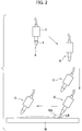
- actions shown in FIG. 2 are to be done. More specifically, it starts moving from a stand-by position (reference position, start position) A of the laser processing head 3, goes through mid-course positions B, C on a predetermined travel path, and then reaches a starting positon D for welding the workpiece W. Next, in a state where it stands still at the starting position D for welding, emission of shield gas SG starts and, after the gas feeding rate of the shield gas SG gets stabilized, the laser beam LB starts being radiated so as to start laser welding.
- a stand-by position (reference position, start position) A of the laser processing head 3 goes through mid-course positions B, C on a predetermined travel path, and then reaches a starting positon D for welding the workpiece W.
- emission of shield gas SG starts and, after the gas feeding rate of the shield gas SG gets stabilized, the laser beam LB starts being radiated so as to start laser welding.
- the laser welding is to be carried out after the feeding rate of the shield gas SG is stabilized.
- the laser welding can be well carried out and fine appearances of weld beads can be improved.
- the standby time required for stabilizing the feeding rate of the shield gas is nevertheless long, and therefore further improvement is desired in order to gain further efficiency of the laser welding.
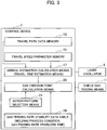
- a control device 7 for controlling action of the laser welding device 1 is constituted in a way as illustrated in FIG. 3 .
- the control device 7 is constituted of a computer, with which a laser oscillator 9 for radiating a laser beam LB emitted through the laser nozzle 5 is connected and, as well, a shield gas feeding means 11 for feeding the laser nozzle 5 with shield gas SG emitted through the laser nozzle 5 is connected.
- the control device 7 is provided with a travel path data memory 13.
- the travel path data memory 13 stores data about the travel path from the start position A for various sets of laser welding to the starting position D for welding the workpiece W. Further, it stores distance data and speed data of plural sections of various travel paths, such as distance data between positions A-B, between positions B-C and between C-D, and speed data.
- control device 7 is provided with a travel speed parameter memory 15.
- This travel speed parameter memory 15 stores data of speeds as parameters corresponding to respective sections in the various travel paths.
- control device 7 is provided with arrival estimation calculation means (travel time calculation means) 17 for calculating a time from starting at the start position A until reaching the starting position D for welding.
- This arrival estimation calculation means 17 is configured to refer the travel path data stored in the travel path data memory 13 and the travel speed data stored in the travel speed parameter memory 15 to calculate a travel time from starting at the start position A until reaching the starting position D for welding.
- the control device 7 is provided with a gas feeding rate stability data table 19.
- This gas feeding rate stability data table 19 stores data about stabilizing times required for stabilizing feeding rates from after starting feeding assist gas from the shield gas feeding means 11 to the laser nozzle 5 until the feeding rates get stabilized.
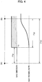
- values corresponding to respective kinds of laser nozzles and respective kinds of shield gas in various welding processing conditions are stored therein. Specifically, as shown in FIG. 4 , times Tg after starting emitting the shield gas through the laser nozzle 5 at an emission instruction time T1 for the shield gas until the gas feeding rates get stabilized are stored in the gas feeding rate data table 19 as corresponding to various welding processing conditions, kinds of laser nozzles and kinds of shield gas.
- the control device 7 is provided with an action pattern selection means (welding pattern selection means) 21.
- This action pattern selection means 21 is configured so that an operator can select and input therein one from a plurality of patterns as to welding patterns. For example, as the welding patterns, two patterns of a first pattern where a fine appearance of the weld bead or such weighs more and a second pattern where efficiency of the laser welding weighs more can be prepared.
- This action pattern selection means 21 may be snap switches connected to the control device 7 for example.
- the action pattern selection means 21 is configured so that an operator when carrying out the laser welding can select and input therein the first pattern or the second pattern. Therefore it is possible to write selection of the first or second pattern in a processing program to carry out the laser welding.
- the control device 7 is provided with a gas emission point calculation means 23.
- This gas emission point calculation means 23 is configured so as to calculate a time Td after the laser processing head 3 starts moving from the start position A until emitting the gas is started (see FIG. 4 ).
- the gas emission point calculation means 23 is so configured as to refer an estimated arrival time Tm calculated by the arrival time estimation calculation means 17 and a gas feeding rate stabilization time Tg stored in the gas feeding rate stability data table 19 to calculate an emission start time Td after starting moving the laser processing head 3 from the start position A until emitting the gas is started.
- the laser processing head 3 starts moving from the start position A and, at a proper position (at a mid-course position C, for example) before reaching the starting position D for welding, emission of the shield gas SG is started, the gas feeding rate of the shield gas will be stabilized as soon as the laser processing head 3 reaches the starting position D for welding.
- the laser processing head 3 reaches the starting position D for welding, radiation of the laser beam LB onto the workpiece W can be started to start the laser welding. Specifically, efficiency of the laser welding can be improved.
- the second pattern is selected by means of the action pattern selection means 21, as described already, at a mid-course position on the way of the laser processing head 3 departing from the start position A but before reaching the starting position D for welding, specifically at the position C for example, emission of the shield gas SG is started.
- the gas feeding rate of the shield gas SG is stabilized.
- the laser processing head 3 is so configured as to act as described with reference to FIG. 2 , thereby improving the fine appearance of the weld bead or such.
- a laser welding device and a laser welding method that can suppress wasted consumption of the shield gas.
Landscapes
- Physics & Mathematics (AREA)
- Optics & Photonics (AREA)
- Engineering & Computer Science (AREA)
- Plasma & Fusion (AREA)
- Mechanical Engineering (AREA)
- Laser Beam Processing (AREA)
Abstract
Description
- The disclosure herein relates to a laser welding device, which is used in a welding robot to enable a laser processing head to be three-dimensionally positioned, and a laser welding method using the same, and in more detail relates to a laser welding device and a laser welding method capable of suppressing consumption of shield gas to be emitted through the laser processing head onto a weld zone.
- In a case where anyone uses a laser welding device such as a welding robot to carry out laser welding on a workpiece for example, it is general to emit assist gas onto a laser weld zone and then carry out the laser welding. The
PTL 1 discloses a related art. - PTL 1: Japanese Patent Application Laid-open No.
2016-93825 -
FIGs. 2 and3 in the patent literature illustrate that sectional shapes of beads depend on kinds of shield gas emitted onto weld zones. Further, thePTL 1 describes that sectional shapes of beads at the weld zones would vary when the feeding rate of the shield gas varied, and this would result in poor welds. - Therefore, execution of successful laser welding requires a condition where the feeding rate of the shield gas is stable at the time of laser welding. Thus, by starting emitting shield gas when the laser processing head is position at a reference position (start position for starting moving), it is possible to stabilize the feeding rate of the shield gas at the time of operation of moving the laser processing head to a starting position for welding the workpiece. In this case, when the laser processing head reaches the starting position for welding, the feeding rate of the shield gas is set in a stable condition and therefore the laser welding can be well carried out.
- In the aforementioned case, however, even in a case where the feeding rate of the shield gas gets stabilized, the laser processing head is still moving toward the starting position for welding and this gives rise to problems in improving effectiveness of the laser welding and as well suppressing consumption of the shield gas.
- The laser welding method is provided with emitting shield gas in advance through a laser nozzle provided on a laser processing head at a time of moving the laser processing head from a reference position to a starting position for welding the workpiece; and radiating a laser beam onto the workpiece through the laser nozzle at the starting position for welding when a feeding rate of the shield gas gets stabilized, thereby perfoming laser welding on the workpiece.
- The laser welding device is provided with a laser processing head being three-dimensionally movable and including a laser nozzle; a shield gas feeding means for feeding shield gas to the laser nozzle; a laser oscillator generating a laser beam to be radiated onto the workpiece through the laser nozzle; and a control device controlling an action of the laser processing head, the shield gas feeding means, and an action of the laser oscillator, the control device including arrival estimation calculation means for referring a travel path and a travel speed of the laser processing head from the reference position to the starting position for welding the workpiece and calculating a travel time of the laser processing head from the reference position to the starting position for welding, a gas feeding rate stability data table storing in advance data of gas feeding rate stability times from starting emitting the shield gas until stabilizing a gas feeding rate and welding conditions, and gas emission point calculation means for referring a result of calculation by the arrival estimation calculation means and the data stored in the gas feeding rate stability data table and calculating a point of time for emitting the shield gas.
- As supply of the shield gas starts at a point of time when the feeding rate of the shield gas gets stabilized just after the laser processing head reaches the starting position for welding the workpiece, it is enabled to suppress wasted consumption of the shield gas. Further, at a time of starting the laser welding, as supply of the shield gas gets stabilized, the laser welding can be well carried out.
-
-
FIG. 1 is a perspective view showing an exterior appearance of a laser welding device. -
FIG. 2 is a schematic elevational view showing a trajectory where a laser processing head moves, along with gas emission. -
FIG. 3 is a block diagram of a control device for controlling action of the laser welding device. -
FIG. 4 is a graph schematically illustrating a relation between start of the gas emission and a time change of a feeding rate of the gas in the course where the laser processing head starts from an initial position and reaches a starting position for welding. -
FIG. 5 is a schematic elevational view showing a trajectory where a laser processing head moves, along with gas emission according to another example. - Exemplary embodiments will be described hereinafter with reference to appended drawings.
- Referring mainly to
FIG. 1 , thelaser welding device 1 is constituted to have alaser processing head 3 at a fore end section of a robot arm in an industrial robot. On thelaser processing head 3 provided is alaser nozzle 5 for radiating a laser beam LB generated by a laser oscillator (not shown) onto a workpiece (not shown). Thelaser nozzle 5 is so constituted as to emit shield gas fed from a shield gas feeding means (not shown) onto a laser welding portion of the workpiece. - Meanwhile, as the
laser welding device 1 as described above has a constitution that has been well-known, descriptions about its detailed constitution and action of thelaser welding device 1 will be omitted. - In a case where laser welding is carried out on a workpiece W by means of the
laser welding device 1, actions shown inFIG. 2 are to be done. More specifically, it starts moving from a stand-by position (reference position, start position) A of thelaser processing head 3, goes through mid-course positions B, C on a predetermined travel path, and then reaches a starting positon D for welding the workpiece W. Next, in a state where it stands still at the starting position D for welding, emission of shield gas SG starts and, after the gas feeding rate of the shield gas SG gets stabilized, the laser beam LB starts being radiated so as to start laser welding. - In the case as described above, the laser welding is to be carried out after the feeding rate of the shield gas SG is stabilized. Thus the laser welding can be well carried out and fine appearances of weld beads can be improved. The standby time required for stabilizing the feeding rate of the shield gas is nevertheless long, and therefore further improvement is desired in order to gain further efficiency of the laser welding.
- Thus a
control device 7 for controlling action of thelaser welding device 1 is constituted in a way as illustrated inFIG. 3 . Specifically, thecontrol device 7 is constituted of a computer, with which alaser oscillator 9 for radiating a laser beam LB emitted through thelaser nozzle 5 is connected and, as well, a shield gas feeding means 11 for feeding thelaser nozzle 5 with shield gas SG emitted through thelaser nozzle 5 is connected. - The
control device 7 is provided with a travelpath data memory 13. The travelpath data memory 13 stores data about the travel path from the start position A for various sets of laser welding to the starting position D for welding the workpiece W. Further, it stores distance data and speed data of plural sections of various travel paths, such as distance data between positions A-B, between positions B-C and between C-D, and speed data. - Further, the
control device 7 is provided with a travelspeed parameter memory 15. This travelspeed parameter memory 15 stores data of speeds as parameters corresponding to respective sections in the various travel paths. - Further, the
control device 7 is provided with arrival estimation calculation means (travel time calculation means) 17 for calculating a time from starting at the start position A until reaching the starting position D for welding. This arrival estimation calculation means 17 is configured to refer the travel path data stored in the travelpath data memory 13 and the travel speed data stored in the travelspeed parameter memory 15 to calculate a travel time from starting at the start position A until reaching the starting position D for welding. - The
control device 7 is provided with a gas feeding rate stability data table 19. This gas feeding rate stability data table 19 stores data about stabilizing times required for stabilizing feeding rates from after starting feeding assist gas from the shield gas feeding means 11 to thelaser nozzle 5 until the feeding rates get stabilized. In regard to the stabilizing times, values corresponding to respective kinds of laser nozzles and respective kinds of shield gas in various welding processing conditions are stored therein. Specifically, as shown inFIG. 4 , times Tg after starting emitting the shield gas through thelaser nozzle 5 at an emission instruction time T1 for the shield gas until the gas feeding rates get stabilized are stored in the gas feeding rate data table 19 as corresponding to various welding processing conditions, kinds of laser nozzles and kinds of shield gas. - Further, the
control device 7 is provided with an action pattern selection means (welding pattern selection means) 21. This action pattern selection means 21 is configured so that an operator can select and input therein one from a plurality of patterns as to welding patterns. For example, as the welding patterns, two patterns of a first pattern where a fine appearance of the weld bead or such weighs more and a second pattern where efficiency of the laser welding weighs more can be prepared. This action pattern selection means 21 may be snap switches connected to thecontrol device 7 for example. Specifically, the action pattern selection means 21 is configured so that an operator when carrying out the laser welding can select and input therein the first pattern or the second pattern. Therefore it is possible to write selection of the first or second pattern in a processing program to carry out the laser welding. - In addition, the
control device 7 is provided with a gas emission point calculation means 23. This gas emission point calculation means 23 is configured so as to calculate a time Td after thelaser processing head 3 starts moving from the start position A until emitting the gas is started (seeFIG. 4 ). Specifically, the gas emission point calculation means 23 is so configured as to refer an estimated arrival time Tm calculated by the arrival time estimation calculation means 17 and a gas feeding rate stabilization time Tg stored in the gas feeding rate stability data table 19 to calculate an emission start time Td after starting moving thelaser processing head 3 from the start position A until emitting the gas is started. In other words, the gas emission point calculation means 23 is so configured as to calculate (emission start time Td = estimated arrival time Tm - gas feeding rate stabilization time Tg). - Therefore, as schematically illustrated in
FIG. 5 , if thelaser processing head 3 starts moving from the start position A and, at a proper position (at a mid-course position C, for example) before reaching the starting position D for welding, emission of the shield gas SG is started, the gas feeding rate of the shield gas will be stabilized as soon as thelaser processing head 3 reaches the starting position D for welding. Thus, as soon as thelaser processing head 3 reaches the starting position D for welding, radiation of the laser beam LB onto the workpiece W can be started to start the laser welding. Specifically, efficiency of the laser welding can be improved. - As being already understood from the above descriptions, if the second pattern is selected by means of the action pattern selection means 21, as described already, at a mid-course position on the way of the
laser processing head 3 departing from the start position A but before reaching the starting position D for welding, specifically at the position C for example, emission of the shield gas SG is started. Next, as soon as thelaser processing head 3 reaches the starting position D for welding, the gas feeding rate of the shield gas SG is stabilized. Thus, as soon as thelaser processing head 3 reaches the starting position D for welding, radiation of the laser beam LB onto the workpiece W can be enabled so as to start the laser welding. Specifically, efficiency of the laser welding can be improved. - In the meantime, also in this second pattern, at a time when the
laser processing head 3 reaches the starting position D for welding, the gas feeding rate of the shield gas SG has been stabilized. Therefore the fine appearance of the weld bead or such is improved. Specifically, both the efficiency and the fine appearance can be improved. - If the first pattern is selected by means of the action pattern selection means 21, the
laser processing head 3 is so configured as to act as described with reference toFIG. 2 , thereby improving the fine appearance of the weld bead or such. - In regard to a timing when the gas feeding rate of the shield gas SG gets stabilized, however, it is desired to make it simultaneous with a timing when the
laser nozzle 5 reaches the starting position D for welding. It could be nevertheless configured so that the gas feeding rate gets stabilized where thelaser nozzle 5 reaches a point at a predetermined distance from the starting position D for welding. Further, it is possible that the gas feeding rate gets stabilized after a predetermined time elapsed after thelaser nozzle 5 reaches the starting position D for welding. - Although certain exemplary embodiments are described above, modifications and variations of the embodiments will occur to those skilled in the art, in light of the above teachings.
- A laser welding device and a laser welding method that can suppress wasted consumption of the shield gas.
Claims (5)
- A laser welding method comprising:emitting shield gas in advance through a laser nozzle provided on a laser processing head at a time of moving the laser processing head from a reference position to a starting position for welding the workpiece; andradiating a laser beam onto the workpiece through the laser nozzle at the starting position for welding when a feeding rate of the shield gas gets stabilized, whereby perfoming laser welding on the workpiece.
- The laser welding method of claim 1, wherein emitting the shield gas is started at a time when the laser nozzle reaches the starting position for welding and then the feeding rate gets stabilized.
- The laser welding method of claim 1, wherein emitting the shield gas is started when an elapsed time after the laser processing head starts moving from the reference position reaches a predetermined time, or when a travel distance reaches a predetermined distance.
- A laser welding device comprising:a laser processing head being three-dimensionally movable and including a laser nozzle;a shield gas feeding means for feeding shield gas to the laser nozzle;a laser oscillator generating a laser beam to be radiated onto the workpiece through the laser nozzle; anda control device controlling an action of the laser processing head, the shield gas feeding means, and an action of the laser oscillator, the control device including arrival estimation calculation means for referring a travel path and a travel speed of the laser processing head from the reference position to the starting position for welding the workpiece and calculating a travel time of the laser processing head from the reference position to the starting position for welding, a gas feeding rate stability data table storing in advance data of gas feeding rate stability times from starting emitting the shield gas until stabilizing a gas feeding rate and welding conditions, and gas emission point calculation means for referring a result of calculation by the arrival estimation calculation means and the data stored in the gas feeding rate stability data table and calculating a point of time for emitting the shield gas.
- The laser welding device of claim 4, further comprising:
welding pattern selection means for inputting a welding pattern including a condition for starting emitting the shield gas.
Applications Claiming Priority (2)
| Application Number | Priority Date | Filing Date | Title |
|---|---|---|---|
| JP2017097228A JP6387436B1 (en) | 2017-05-16 | 2017-05-16 | Laser welding method and laser welding apparatus |
| PCT/JP2018/016925 WO2018211937A1 (en) | 2017-05-16 | 2018-04-26 | Laser welding method and laser welding device |
Publications (3)
| Publication Number | Publication Date |
|---|---|
| EP3626382A1 true EP3626382A1 (en) | 2020-03-25 |
| EP3626382A4 EP3626382A4 (en) | 2020-05-27 |
| EP3626382B1 EP3626382B1 (en) | 2022-06-08 |
Family
ID=63444209
Family Applications (1)
| Application Number | Title | Priority Date | Filing Date |
|---|---|---|---|
| EP18801873.3A Active EP3626382B1 (en) | 2017-05-16 | 2018-04-26 | Laser welding method and laser welding device |
Country Status (5)
| Country | Link |
|---|---|
| US (1) | US11235421B2 (en) |
| EP (1) | EP3626382B1 (en) |
| JP (1) | JP6387436B1 (en) |
| CN (1) | CN110769969B (en) |
| WO (1) | WO2018211937A1 (en) |
Families Citing this family (2)
| Publication number | Priority date | Publication date | Assignee | Title |
|---|---|---|---|---|
| US20240009758A1 (en) * | 2020-08-25 | 2024-01-11 | Ipg Photonics Corporation | Handheld laser system |
| CN119546409A (en) * | 2022-08-10 | 2025-02-28 | 发那科株式会社 | Numerical control device |
Family Cites Families (20)
| Publication number | Priority date | Publication date | Assignee | Title |
|---|---|---|---|---|
| US4023006A (en) * | 1971-11-06 | 1977-05-10 | Rolls-Royce (1971) Limited | Plasma arc welding method |
| JPS6363597A (en) * | 1986-09-05 | 1988-03-19 | Kawasaki Steel Corp | Laser beam machining method |
| JPS6444296A (en) | 1987-08-12 | 1989-02-16 | Fanuc Ltd | Assist gas control system |
| JP2803902B2 (en) * | 1990-11-15 | 1998-09-24 | ジューキ 株式会社 | Cutting device |
| JP2587137Y2 (en) * | 1992-07-10 | 1998-12-14 | アラコ株式会社 | Laser welding equipment |
| JP3244319B2 (en) * | 1992-12-28 | 2002-01-07 | ファナック株式会社 | Laser processing equipment |
| JP3500071B2 (en) * | 1998-07-23 | 2004-02-23 | 株式会社日平トヤマ | Laser processing method and laser processing apparatus |
| JP3484994B2 (en) * | 1998-10-12 | 2004-01-06 | スズキ株式会社 | Laser welding equipment |
| JP4193081B2 (en) * | 1998-12-08 | 2008-12-10 | 日産自動車株式会社 | Center gas nozzle for laser processing |
| JP3385361B2 (en) * | 2000-05-09 | 2003-03-10 | 北海道大学長 | Laser welding method and laser welding apparatus |
| EP1695788B1 (en) * | 2005-02-25 | 2011-04-06 | TRUMPF Werkzeugmaschinen GmbH + Co. KG | Process for spooling the conduits and/or the hollow spaces of a laser machining machine |
| JP2008068305A (en) * | 2006-09-15 | 2008-03-27 | Mitsubishi Electric Corp | Laser processing method and laser processing apparatus |
| JP5459707B2 (en) | 2010-02-03 | 2014-04-02 | 株式会社ダイヘン | Control device for arc welding robot |
| CN103212801A (en) * | 2012-01-19 | 2013-07-24 | 昆山思拓机器有限公司 | Cutting nozzle for stabilizing position of focus by utilizing gas flow |
| WO2014206432A1 (en) * | 2013-06-28 | 2014-12-31 | Trumpf Laser- Und Systemtechnik Gmbh | Process for machining, in particular for mechanical welding, and control apparatus for a setting device of a process gas feed |
| CN104511691B (en) * | 2013-09-29 | 2016-03-30 | 宝山钢铁股份有限公司 | A kind of laser beam outside optical system of laser-beam welding machine |
| DE102014203576A1 (en) * | 2014-02-27 | 2015-08-27 | Trumpf Laser- Und Systemtechnik Gmbh | Laser processing head with a crossjet nozzle close to the workpiece |
| JP6044577B2 (en) * | 2014-03-31 | 2016-12-14 | ブラザー工業株式会社 | Laser machining apparatus, machining data creation apparatus, and program |
| JP5902747B2 (en) * | 2014-04-30 | 2016-04-13 | ファナック株式会社 | Laser processing system with processing resumption preparation function |
| JP6137130B2 (en) | 2014-11-14 | 2017-05-31 | トヨタ自動車株式会社 | Laser welding apparatus and laser welding method |
-
2017
- 2017-05-16 JP JP2017097228A patent/JP6387436B1/en active Active
-
2018
- 2018-04-26 CN CN201880032148.XA patent/CN110769969B/en active Active
- 2018-04-26 WO PCT/JP2018/016925 patent/WO2018211937A1/en not_active Ceased
- 2018-04-26 US US16/612,923 patent/US11235421B2/en active Active
- 2018-04-26 EP EP18801873.3A patent/EP3626382B1/en active Active
Also Published As
| Publication number | Publication date |
|---|---|
| WO2018211937A1 (en) | 2018-11-22 |
| US20200198056A1 (en) | 2020-06-25 |
| EP3626382B1 (en) | 2022-06-08 |
| US11235421B2 (en) | 2022-02-01 |
| JP2018192494A (en) | 2018-12-06 |
| CN110769969A (en) | 2020-02-07 |
| JP6387436B1 (en) | 2018-09-05 |
| CN110769969B (en) | 2021-01-12 |
| EP3626382A4 (en) | 2020-05-27 |
Similar Documents
| Publication | Publication Date | Title |
|---|---|---|
| US10207364B2 (en) | Laser welding condition determination method and laser welding device | |
| JP5752335B1 (en) | NC program generating device, NC program generating method, NC program generating program | |
| US20150251267A1 (en) | System and method for integrated controller | |
| TWI714792B (en) | A method of laser processing of a metallic material, as well as a machine and a computer program for the implementation of said method | |
| KR101626312B1 (en) | Laser cutting method and laser cutting device | |
| US11235421B2 (en) | Laser welding method and laser welding device | |
| EP3578291B1 (en) | Additive manufacturing system, and additive manufacturing method | |
| US20100270274A1 (en) | Use of Beam Deflection to Control an Electron Beam Wire Deposition Process | |
| JP5201114B2 (en) | Laser processing apparatus and laser processing method | |
| US20160045984A1 (en) | Laser Processor and Hole-opening Processing Method | |
| US20070023408A1 (en) | Welding system and method | |
| WO2020079829A1 (en) | Numerical control device and method for controlling additive manufacturing device | |
| KR20180070055A (en) | Cutting machine with cooling device | |
| JP6719683B2 (en) | Cutting machine and cutting method | |
| WO2021220957A1 (en) | Robot system, robot control device, control method, and computer program | |
| KR102463759B1 (en) | Position control apparatus and method of 3d printing device | |
| JP6192206B2 (en) | Cutting method and cutting apparatus | |
| JP5846760B2 (en) | Groove machining program, control system, and plasma cutting device | |
| JP7469575B1 (en) | Apparatus and method for correcting command value or teaching point, laser processing system, and computer program | |
| US20250010397A1 (en) | Laser processing system and control device | |
| US20200398380A1 (en) | Cutting processing machine and cutting processing method | |
| JP2015139778A (en) | Laser processing apparatus and laser processing method | |
| JP7293700B2 (en) | LASER PROCESSING APPARATUS AND LASER PROCESSING METHOD | |
| CN120563669A (en) | Graphic filling method, processing equipment, system, readable medium and program product |
Legal Events
| Date | Code | Title | Description |
|---|---|---|---|
| STAA | Information on the status of an ep patent application or granted ep patent |
Free format text: STATUS: THE INTERNATIONAL PUBLICATION HAS BEEN MADE |
|
| PUAI | Public reference made under article 153(3) epc to a published international application that has entered the european phase |
Free format text: ORIGINAL CODE: 0009012 |
|
| STAA | Information on the status of an ep patent application or granted ep patent |
Free format text: STATUS: REQUEST FOR EXAMINATION WAS MADE |
|
| 17P | Request for examination filed |
Effective date: 20191209 |
|
| AK | Designated contracting states |
Kind code of ref document: A1 Designated state(s): AL AT BE BG CH CY CZ DE DK EE ES FI FR GB GR HR HU IE IS IT LI LT LU LV MC MK MT NL NO PL PT RO RS SE SI SK SM TR |
|
| AX | Request for extension of the european patent |
Extension state: BA ME |
|
| A4 | Supplementary search report drawn up and despatched |
Effective date: 20200423 |
|
| RIC1 | Information provided on ipc code assigned before grant |
Ipc: B23K 26/21 20140101ALI20200417BHEP Ipc: B23K 26/00 20140101ALI20200417BHEP Ipc: B23K 26/14 20140101AFI20200417BHEP Ipc: B23K 26/08 20140101ALI20200417BHEP |
|
| DAV | Request for validation of the european patent (deleted) | ||
| DAX | Request for extension of the european patent (deleted) | ||
| STAA | Information on the status of an ep patent application or granted ep patent |
Free format text: STATUS: EXAMINATION IS IN PROGRESS |
|
| 17Q | First examination report despatched |
Effective date: 20210209 |
|
| GRAP | Despatch of communication of intention to grant a patent |
Free format text: ORIGINAL CODE: EPIDOSNIGR1 |
|
| STAA | Information on the status of an ep patent application or granted ep patent |
Free format text: STATUS: GRANT OF PATENT IS INTENDED |
|
| INTG | Intention to grant announced |
Effective date: 20211220 |
|
| GRAS | Grant fee paid |
Free format text: ORIGINAL CODE: EPIDOSNIGR3 |
|
| GRAA | (expected) grant |
Free format text: ORIGINAL CODE: 0009210 |
|
| STAA | Information on the status of an ep patent application or granted ep patent |
Free format text: STATUS: THE PATENT HAS BEEN GRANTED |
|
| AK | Designated contracting states |
Kind code of ref document: B1 Designated state(s): AL AT BE BG CH CY CZ DE DK EE ES FI FR GB GR HR HU IE IS IT LI LT LU LV MC MK MT NL NO PL PT RO RS SE SI SK SM TR |
|
| REG | Reference to a national code |
Ref country code: AT Ref legal event code: REF Ref document number: 1496581 Country of ref document: AT Kind code of ref document: T Effective date: 20220615 Ref country code: CH Ref legal event code: EP |
|
| REG | Reference to a national code |
Ref country code: DE Ref legal event code: R096 Ref document number: 602018036578 Country of ref document: DE |
|
| REG | Reference to a national code |
Ref country code: IE Ref legal event code: FG4D |
|
| REG | Reference to a national code |
Ref country code: LT Ref legal event code: MG9D |
|
| REG | Reference to a national code |
Ref country code: NL Ref legal event code: MP Effective date: 20220608 |
|
| PG25 | Lapsed in a contracting state [announced via postgrant information from national office to epo] |
Ref country code: SE Free format text: LAPSE BECAUSE OF FAILURE TO SUBMIT A TRANSLATION OF THE DESCRIPTION OR TO PAY THE FEE WITHIN THE PRESCRIBED TIME-LIMIT Effective date: 20220608 Ref country code: NO Free format text: LAPSE BECAUSE OF FAILURE TO SUBMIT A TRANSLATION OF THE DESCRIPTION OR TO PAY THE FEE WITHIN THE PRESCRIBED TIME-LIMIT Effective date: 20220908 Ref country code: LT Free format text: LAPSE BECAUSE OF FAILURE TO SUBMIT A TRANSLATION OF THE DESCRIPTION OR TO PAY THE FEE WITHIN THE PRESCRIBED TIME-LIMIT Effective date: 20220608 Ref country code: HR Free format text: LAPSE BECAUSE OF FAILURE TO SUBMIT A TRANSLATION OF THE DESCRIPTION OR TO PAY THE FEE WITHIN THE PRESCRIBED TIME-LIMIT Effective date: 20220608 Ref country code: GR Free format text: LAPSE BECAUSE OF FAILURE TO SUBMIT A TRANSLATION OF THE DESCRIPTION OR TO PAY THE FEE WITHIN THE PRESCRIBED TIME-LIMIT Effective date: 20220909 Ref country code: FI Free format text: LAPSE BECAUSE OF FAILURE TO SUBMIT A TRANSLATION OF THE DESCRIPTION OR TO PAY THE FEE WITHIN THE PRESCRIBED TIME-LIMIT Effective date: 20220608 Ref country code: ES Free format text: LAPSE BECAUSE OF FAILURE TO SUBMIT A TRANSLATION OF THE DESCRIPTION OR TO PAY THE FEE WITHIN THE PRESCRIBED TIME-LIMIT Effective date: 20220608 Ref country code: BG Free format text: LAPSE BECAUSE OF FAILURE TO SUBMIT A TRANSLATION OF THE DESCRIPTION OR TO PAY THE FEE WITHIN THE PRESCRIBED TIME-LIMIT Effective date: 20220908 |
|
| REG | Reference to a national code |
Ref country code: AT Ref legal event code: MK05 Ref document number: 1496581 Country of ref document: AT Kind code of ref document: T Effective date: 20220608 |
|
| PG25 | Lapsed in a contracting state [announced via postgrant information from national office to epo] |
Ref country code: RS Free format text: LAPSE BECAUSE OF FAILURE TO SUBMIT A TRANSLATION OF THE DESCRIPTION OR TO PAY THE FEE WITHIN THE PRESCRIBED TIME-LIMIT Effective date: 20220608 Ref country code: LV Free format text: LAPSE BECAUSE OF FAILURE TO SUBMIT A TRANSLATION OF THE DESCRIPTION OR TO PAY THE FEE WITHIN THE PRESCRIBED TIME-LIMIT Effective date: 20220608 |
|
| PG25 | Lapsed in a contracting state [announced via postgrant information from national office to epo] |
Ref country code: NL Free format text: LAPSE BECAUSE OF FAILURE TO SUBMIT A TRANSLATION OF THE DESCRIPTION OR TO PAY THE FEE WITHIN THE PRESCRIBED TIME-LIMIT Effective date: 20220608 |
|
| PG25 | Lapsed in a contracting state [announced via postgrant information from national office to epo] |
Ref country code: SM Free format text: LAPSE BECAUSE OF FAILURE TO SUBMIT A TRANSLATION OF THE DESCRIPTION OR TO PAY THE FEE WITHIN THE PRESCRIBED TIME-LIMIT Effective date: 20220608 Ref country code: SK Free format text: LAPSE BECAUSE OF FAILURE TO SUBMIT A TRANSLATION OF THE DESCRIPTION OR TO PAY THE FEE WITHIN THE PRESCRIBED TIME-LIMIT Effective date: 20220608 Ref country code: RO Free format text: LAPSE BECAUSE OF FAILURE TO SUBMIT A TRANSLATION OF THE DESCRIPTION OR TO PAY THE FEE WITHIN THE PRESCRIBED TIME-LIMIT Effective date: 20220608 Ref country code: PT Free format text: LAPSE BECAUSE OF FAILURE TO SUBMIT A TRANSLATION OF THE DESCRIPTION OR TO PAY THE FEE WITHIN THE PRESCRIBED TIME-LIMIT Effective date: 20221010 Ref country code: EE Free format text: LAPSE BECAUSE OF FAILURE TO SUBMIT A TRANSLATION OF THE DESCRIPTION OR TO PAY THE FEE WITHIN THE PRESCRIBED TIME-LIMIT Effective date: 20220608 Ref country code: CZ Free format text: LAPSE BECAUSE OF FAILURE TO SUBMIT A TRANSLATION OF THE DESCRIPTION OR TO PAY THE FEE WITHIN THE PRESCRIBED TIME-LIMIT Effective date: 20220608 Ref country code: AT Free format text: LAPSE BECAUSE OF FAILURE TO SUBMIT A TRANSLATION OF THE DESCRIPTION OR TO PAY THE FEE WITHIN THE PRESCRIBED TIME-LIMIT Effective date: 20220608 |
|
| PG25 | Lapsed in a contracting state [announced via postgrant information from national office to epo] |
Ref country code: PL Free format text: LAPSE BECAUSE OF FAILURE TO SUBMIT A TRANSLATION OF THE DESCRIPTION OR TO PAY THE FEE WITHIN THE PRESCRIBED TIME-LIMIT Effective date: 20220608 Ref country code: IS Free format text: LAPSE BECAUSE OF FAILURE TO SUBMIT A TRANSLATION OF THE DESCRIPTION OR TO PAY THE FEE WITHIN THE PRESCRIBED TIME-LIMIT Effective date: 20221008 |
|
| REG | Reference to a national code |
Ref country code: DE Ref legal event code: R097 Ref document number: 602018036578 Country of ref document: DE |
|
| PG25 | Lapsed in a contracting state [announced via postgrant information from national office to epo] |
Ref country code: AL Free format text: LAPSE BECAUSE OF FAILURE TO SUBMIT A TRANSLATION OF THE DESCRIPTION OR TO PAY THE FEE WITHIN THE PRESCRIBED TIME-LIMIT Effective date: 20220608 |
|
| PLBE | No opposition filed within time limit |
Free format text: ORIGINAL CODE: 0009261 |
|
| STAA | Information on the status of an ep patent application or granted ep patent |
Free format text: STATUS: NO OPPOSITION FILED WITHIN TIME LIMIT |
|
| PG25 | Lapsed in a contracting state [announced via postgrant information from national office to epo] |
Ref country code: DK Free format text: LAPSE BECAUSE OF FAILURE TO SUBMIT A TRANSLATION OF THE DESCRIPTION OR TO PAY THE FEE WITHIN THE PRESCRIBED TIME-LIMIT Effective date: 20220608 |
|
| 26N | No opposition filed |
Effective date: 20230310 |
|
| PG25 | Lapsed in a contracting state [announced via postgrant information from national office to epo] |
Ref country code: SI Free format text: LAPSE BECAUSE OF FAILURE TO SUBMIT A TRANSLATION OF THE DESCRIPTION OR TO PAY THE FEE WITHIN THE PRESCRIBED TIME-LIMIT Effective date: 20220608 |
|
| P01 | Opt-out of the competence of the unified patent court (upc) registered |
Effective date: 20230428 |
|
| REG | Reference to a national code |
Ref country code: CH Ref legal event code: PL |
|
| GBPC | Gb: european patent ceased through non-payment of renewal fee |
Effective date: 20230426 |
|
| PG25 | Lapsed in a contracting state [announced via postgrant information from national office to epo] |
Ref country code: LU Free format text: LAPSE BECAUSE OF NON-PAYMENT OF DUE FEES Effective date: 20230426 |
|
| REG | Reference to a national code |
Ref country code: BE Ref legal event code: MM Effective date: 20230430 |
|
| PG25 | Lapsed in a contracting state [announced via postgrant information from national office to epo] |
Ref country code: MC Free format text: LAPSE BECAUSE OF FAILURE TO SUBMIT A TRANSLATION OF THE DESCRIPTION OR TO PAY THE FEE WITHIN THE PRESCRIBED TIME-LIMIT Effective date: 20220608 |
|
| PG25 | Lapsed in a contracting state [announced via postgrant information from national office to epo] |
Ref country code: GB Free format text: LAPSE BECAUSE OF NON-PAYMENT OF DUE FEES Effective date: 20230426 |
|
| PG25 | Lapsed in a contracting state [announced via postgrant information from national office to epo] |
Ref country code: MC Free format text: LAPSE BECAUSE OF FAILURE TO SUBMIT A TRANSLATION OF THE DESCRIPTION OR TO PAY THE FEE WITHIN THE PRESCRIBED TIME-LIMIT Effective date: 20220608 Ref country code: LI Free format text: LAPSE BECAUSE OF NON-PAYMENT OF DUE FEES Effective date: 20230430 Ref country code: IT Free format text: LAPSE BECAUSE OF FAILURE TO SUBMIT A TRANSLATION OF THE DESCRIPTION OR TO PAY THE FEE WITHIN THE PRESCRIBED TIME-LIMIT Effective date: 20220608 Ref country code: GB Free format text: LAPSE BECAUSE OF NON-PAYMENT OF DUE FEES Effective date: 20230426 Ref country code: FR Free format text: LAPSE BECAUSE OF NON-PAYMENT OF DUE FEES Effective date: 20230430 Ref country code: CH Free format text: LAPSE BECAUSE OF NON-PAYMENT OF DUE FEES Effective date: 20230430 |
|
| REG | Reference to a national code |
Ref country code: IE Ref legal event code: MM4A |
|
| PG25 | Lapsed in a contracting state [announced via postgrant information from national office to epo] |
Ref country code: BE Free format text: LAPSE BECAUSE OF NON-PAYMENT OF DUE FEES Effective date: 20230430 |
|
| PG25 | Lapsed in a contracting state [announced via postgrant information from national office to epo] |
Ref country code: IE Free format text: LAPSE BECAUSE OF NON-PAYMENT OF DUE FEES Effective date: 20230426 |
|
| PG25 | Lapsed in a contracting state [announced via postgrant information from national office to epo] |
Ref country code: IE Free format text: LAPSE BECAUSE OF NON-PAYMENT OF DUE FEES Effective date: 20230426 |
|
| PG25 | Lapsed in a contracting state [announced via postgrant information from national office to epo] |
Ref country code: BG Free format text: LAPSE BECAUSE OF FAILURE TO SUBMIT A TRANSLATION OF THE DESCRIPTION OR TO PAY THE FEE WITHIN THE PRESCRIBED TIME-LIMIT Effective date: 20220608 |
|
| PG25 | Lapsed in a contracting state [announced via postgrant information from national office to epo] |
Ref country code: BG Free format text: LAPSE BECAUSE OF FAILURE TO SUBMIT A TRANSLATION OF THE DESCRIPTION OR TO PAY THE FEE WITHIN THE PRESCRIBED TIME-LIMIT Effective date: 20220608 |
|
| PGFP | Annual fee paid to national office [announced via postgrant information from national office to epo] |
Ref country code: DE Payment date: 20250422 Year of fee payment: 8 |
|
| PG25 | Lapsed in a contracting state [announced via postgrant information from national office to epo] |
Ref country code: CY Free format text: LAPSE BECAUSE OF FAILURE TO SUBMIT A TRANSLATION OF THE DESCRIPTION OR TO PAY THE FEE WITHIN THE PRESCRIBED TIME-LIMIT; INVALID AB INITIO Effective date: 20180426 |
|
| PG25 | Lapsed in a contracting state [announced via postgrant information from national office to epo] |
Ref country code: HU Free format text: LAPSE BECAUSE OF FAILURE TO SUBMIT A TRANSLATION OF THE DESCRIPTION OR TO PAY THE FEE WITHIN THE PRESCRIBED TIME-LIMIT; INVALID AB INITIO Effective date: 20180426 |
|
| PG25 | Lapsed in a contracting state [announced via postgrant information from national office to epo] |
Ref country code: TR Free format text: LAPSE BECAUSE OF FAILURE TO SUBMIT A TRANSLATION OF THE DESCRIPTION OR TO PAY THE FEE WITHIN THE PRESCRIBED TIME-LIMIT Effective date: 20220608 |