EP3626088A1 - Vaporization device and cartridge thereof - Google Patents
Vaporization device and cartridge thereof Download PDFInfo
- Publication number
- EP3626088A1 EP3626088A1 EP19197173.8A EP19197173A EP3626088A1 EP 3626088 A1 EP3626088 A1 EP 3626088A1 EP 19197173 A EP19197173 A EP 19197173A EP 3626088 A1 EP3626088 A1 EP 3626088A1
- Authority
- EP
- European Patent Office
- Prior art keywords
- ventilation pipe
- atomization
- cartridge
- channel
- ventilation
- Prior art date
- Legal status (The legal status is an assumption and is not a legal conclusion. Google has not performed a legal analysis and makes no representation as to the accuracy of the status listed.)
- Pending
Links
Images


Classifications
-
- A—HUMAN NECESSITIES
- A24—TOBACCO; CIGARS; CIGARETTES; SIMULATED SMOKING DEVICES; SMOKERS' REQUISITES
- A24F—SMOKERS' REQUISITES; MATCH BOXES; SIMULATED SMOKING DEVICES
- A24F40/00—Electrically operated smoking devices; Component parts thereof; Manufacture thereof; Maintenance or testing thereof; Charging means specially adapted therefor
- A24F40/40—Constructional details, e.g. connection of cartridges and battery parts
- A24F40/42—Cartridges or containers for inhalable precursors
-
- A—HUMAN NECESSITIES
- A24—TOBACCO; CIGARS; CIGARETTES; SIMULATED SMOKING DEVICES; SMOKERS' REQUISITES
- A24F—SMOKERS' REQUISITES; MATCH BOXES; SIMULATED SMOKING DEVICES
- A24F40/00—Electrically operated smoking devices; Component parts thereof; Manufacture thereof; Maintenance or testing thereof; Charging means specially adapted therefor
- A24F40/10—Devices using liquid inhalable precursors
Definitions
- the utility relates to the field of cigarette substitutes, and specifically to a vaporization device and a cartridge thereof.
- the electronic cigarette is also called as a virtual cigarette or a vaporization device. As a substitute of the cigarette, the electronic cigarette is mostly used for smoking cessation.
- the electronic cigarette has similar appearance and taste with the cigarette, but often does not contain other harmful ingredients, such as, tar, suspended particles, and the like, in the cigarette.
- the vaporization device is mainly formed of a cartridge and a body with a power supply and a puff sensor therein. Condensate produced during drawing by a user is accumulated on a ventilation hole.
- aerosol-generating substrate usually a liquid
- aerosol-generating substrate has the phenomenon of frying oil due to atomization
- the aerosol-generating substrate is sputtered onto the ventilation hole at an atomizer base.
- the vaporization device also has the phenomenon of liquid leakage due to action of a negative pressure. The leakage liquid can be leaked to the outside of the vaporization device through the ventilation hole, and/or flow to the body, which causes damage to the body and the puff sensor thereof and brings a bad usage experience to the user.
- the technical problem to be solved by the utility is to provide a vaporization device and a cartridge thereof capable of preventing condensed liquid from flowing to a body.
- the technical solution of the utility adopted to solve the technical problem is to construct a cartridge applied to a vaporization device, the vaporization device comprises a body with a power supply therein, wherein; the cartridge comprises an atomization base, wherein an airflow channel passing through the atomization base is arranged in the cartridge; the atomization base defines at least one ventilation hole, a ventilation pipe extends from the ventilation hole, resulting in one end of the ventilation pipe extending into the airflow channel, and the other end being in fluid communication with a puff sensor in the body.
- the ventilation pipe is disposed on the atomization base, and the ventilation pipe is higher than a surface of the atomization base.
- the cartridge further comprises an atomization assembly disposed on the atomization base for heating and atomizing aerosol-generating substrate, and the ventilation pipe and the atomization assembly are staggered in a flow direction of the airflow channel.
- the airflow channel comprises an atomization channel passing through the atomization base, and an air inlet channel and an air outlet channel respectively in communication with two ends of the atomization channel, and the ventilation pipe and the atomization assembly are arranged along a flow direction of the air inlet channel towards the air outlet channel.
- the ventilation pipe is made of a metal material.
- the ventilation pipe is an elongated pipe with an inner diameter from 0.6 mm to 1.0 mm, and a length from 3 mm to 8 mm.
- the ventilation pipe is further provided with a breathable separator that prevents liquid from flowing out via the ventilation pipe.
- the ventilation pipe comprises a breathable cotton or a breathable membrane.
- a gap is reserved between one end of the ventilation pipe away from the airflow channel and an end surface of the connecting end, wherein an airflow slot in communication with the ventilation pipe is provided in the end surface of the connecting end.
- a vaporization device comprising:
- the airflow channel comprises an air inlet channel, an atomization channel and an air outlet channel; wherein the environment air flows through the air inlet channel, the atomization channel and the air outlet channel when a user draws.
- the atomization base comprises a ventilation pipe, wherein one end of the ventilation pipe is in fluid communication with the atomization channel, and the other end of the ventilation pipe is in fluid communication with the puff sensor.
- a side of the atomization channel is formed by a surface of the atomization base, and the ventilation pipe is higher than the surface of the atomization base.
- the cartridge further comprises an atomization assembly disposed on the atomization base for heating and atomizing aerosol-generating substrate, and the ventilation pipe and the atomization assembly are staggered in a flow direction of the airflow channel.
- the ventilation pipe is made of a metal material.
- the ventilation pipe is further provided with a breathable separator that prevents liquid from flowing out via the ventilation pipe.
- the ventilation pipe extends from the ventilation hole into the airflow channel to locate above a surface of the atomization base, so if the cartridge has a liquid leakage, it is not easy to enter into the ventilation pipe, such that the risk of entering from the ventilation pipe into the body and the puff sensor thereof can be reduced.
- a vaporization device in one preferable embodiment of the utility comprises a cartridge 1 and a body 2.
- the body 2 comprises a power supply configured to electrically connect with the cartridge 1 and supply power to the cartridge 1.
- the cartridge 1 comprises a connecting end butted with the body 2, and after the connecting end is butted with the body 2, the body 2 can power the cartridge 1.
- the cartridge 1 comprises an atomization base 11, and an atomization assembly 12 disposed on the atomization base 11 for heating and atomizing aerosol-generating substrate (usually a liquid), and the cartridge 1 is provided with an airflow channel 13 passing through the atomization base 11.
- an aerosol produced by the atomization assembly 12 on the atomization base 11 for heating aerosol-generating substrate is brought to a suction nozzle 14 for user drawing.
- the atomization base 11 defines at least one ventilation hole 111.
- a ventilation pipe 15 extends from the ventilation hole 111, resulting in one end of the ventilation pipe 15 extending into the airflow channel 13, and the other end being in fluid communication with a puff sensor 21 in the body 2.
- the puff sensor 21 is a microphone arranged in the body 2, and when the puff sensor 21 senses a gas flowing and transmits a signal to a controller, the body 2 is turned on to power the cartridge 1.
- the ventilation pipe 15 is disposed on the atomization base 11, and extends into the airflow channel 13 to locate above a surface of the atomization base 11, wherein the surface of the atomization base 11 defines at least a side of airflow channel 13. That is, the ventilation pipe 15 is higher than the surface of the atomization base 11. So if the cartridge 1 has a liquid leakage, it is not easy to enter into the ventilation pipe 15, such that the risk of entering from the ventilation pipe 15 into the body 2 can be reduced.
- the ventilation pipe 15 is an independent component, and the ventilation pipe 15 is plugged into the atomization base 11 to make production and installation simpler.
- the ventilation pipe 15 is made of a metal material, preferably, stainless steel, which is easily formed and prevents rust.
- the ventilation pipe 15 and the atomization assembly 12 are staggered in a flow direction of the airflow channel 13, for example, the ventilation pipe 15 isn't located right below the atomization assembly 12 in this embodiment, so as to avoid condensed liquid below the atomization assembly 12 from directly falling into the ventilation pipe 15, to reduce the risk of the liquid flowing from the ventilation pipe 15 to one side of the body 2, and to reduce the risk of blockage of the ventilation pipe 15 by the liquid, so as to improve smoothness of the airflow.
- the airflow channel 13 comprises an atomization channel 131 passing through the atomization base 11, and an air inlet channel 132 and an air outlet channel 133 respectively in communication with two ends of the atomization channel 131.
- the environment air flows sequentially through the air inlet channel 132, the atomization channel 131, and the air outlet channel 133 to the suction nozzle 14, bringing the aerosol atomized by the atomization assembly 12 to be drawn by the user.
- the ventilation pipe 15 and the atomization assembly 12 are arranged along a flow direction of the air inlet channel 132 towards the air outlet channel 133, such that the ventilation pipe 15 is on one side of the atomization base 11.
- a part of gas flows to the body 2 via the ventilation pipe 15, to turn on the puff sensor 21, and another part of other gas flows to the atomization assembly 12 to participate in heating and atomizing. Therefore, gas has flown to the body 2 before reaching the atomization assembly 12, and the ventilation pipe is above the atomization base 11, so that it won't have aerosol-generating substrate flowing into the ventilation pipe 15, which reduces influence of the condensate on the airflow.
- the atomization channel 131 transversely passes through the atomization base 11, and an extending direction of the atomization channel 131 is perpendicular to an axial direction of the vaporization device.
- Disposing the ventilation pipe 15 on one side of the atomization base 11 makes airflow of the entire cartridge 1 more smooth. Disposing the ventilation pipe 15 on one side of the atomization base 11 can reduce influence of the condensate on the airflow, so as to make the airflow more smooth, and have a better atomization effect.
- the ventilation pipes 15 when there are a plurality of ventilation holes 111 and ventilation pipes 15, respectively, the ventilation pipes 15 also can be respectively disposed on two sides of the atomization base 11, or the plurality of ventilation pipes 15 are on the same side of the atomization base 11.
- the ventilation pipe 15 is an elongated pipe. As the ventilation pipe 15 is thin and long, little condensate is attached on the ventilation pipe 15 because of surface tension, and does not easily enter into the body 2. Since the ventilation pipe is thin and long, and is above a surface of the atomization base 11, when the atomization base 11 has liquid leakage, it is also not easy to enter into the ventilation pipe 15 even if shaking in transportation.
- the ventilation pipe 15 has an inner diameter from 0.6 mm to 1.0 mm, such as, 0.6 mm, 0.7 mm, 0.8 mm, 0.9 mm, or the like, and a length from 3 mm to 8 mm, such as, 3 mm, 4 mm, 5 mm, 6 mm, 7 mm, 8 mm, or the like. In these ranges, ventilation effect can be ensured, and liquid leakage also can be effectively prevented.
- the ventilation pipe 15 is further provided with a breathable separator 151 that prevents liquid from flowing out via the ventilation pipe 15.
- the separator 151 can further prevent leaking liquid and condensate from flowing to the body 2.
- the separator 151 comprises a breathable cotton or a breathable membrane disposed on one end of the ventilation pipe 15 close to the body 2, which can breathe, and also can prevent liquid from flowing.
- a gap is reserved between one end of the ventilation pipe 15 away from the airflow channel 13 and an end surface of the connecting end, where an airflow slot 16 in communication with the ventilation pipe 15 in the end surface of the connecting end is provided, to enable gas to flow to the puff sensor 21 through the ventilation pipe 15.
Landscapes
- Nozzles (AREA)
- Electrostatic Spraying Apparatus (AREA)
Abstract
Description
- The utility relates to the field of cigarette substitutes, and specifically to a vaporization device and a cartridge thereof.
- The electronic cigarette is also called as a virtual cigarette or a vaporization device. As a substitute of the cigarette, the electronic cigarette is mostly used for smoking cessation. The electronic cigarette has similar appearance and taste with the cigarette, but often does not contain other harmful ingredients, such as, tar, suspended particles, and the like, in the cigarette.
- The vaporization device is mainly formed of a cartridge and a body with a power supply and a puff sensor therein. Condensate produced during drawing by a user is accumulated on a ventilation hole. During drawing, aerosol-generating substrate (usually a liquid) has the phenomenon of frying oil due to atomization, and the aerosol-generating substrate is sputtered onto the ventilation hole at an atomizer base. If placed for a long time, the vaporization device also has the phenomenon of liquid leakage due to action of a negative pressure. The leakage liquid can be leaked to the outside of the vaporization device through the ventilation hole, and/or flow to the body, which causes damage to the body and the puff sensor thereof and brings a bad usage experience to the user.
- In addition, since the previous ventilation hole is disposed under an atomizing core, more condensate is often accumulated under the atomizing core, and During drawing, due to issue of accumulation of the condensate, airflow of the ventilation hole is affected by the condensate, causing blockage of the airflow.
- The technical problem to be solved by the utility is to provide a vaporization device and a cartridge thereof capable of preventing condensed liquid from flowing to a body.
- The technical solution of the utility adopted to solve the technical problem is to construct a cartridge applied to a vaporization device, the vaporization device comprises a body with a power supply therein, wherein;
the cartridge comprises an atomization base, wherein an airflow channel passing through the atomization base is arranged in the cartridge;
the atomization base defines at least one ventilation hole, a ventilation pipe extends from the ventilation hole, resulting in one end of the ventilation pipe extending into the airflow channel, and the other end being in fluid communication with a puff sensor in the body. - Preferably, the ventilation pipe is disposed on the atomization base, and the ventilation pipe is higher than a surface of the atomization base.
- Preferably, the cartridge further comprises an atomization assembly disposed on the atomization base for heating and atomizing aerosol-generating substrate, and the ventilation pipe and the atomization assembly are staggered in a flow direction of the airflow channel.
- Preferably, the airflow channel comprises an atomization channel passing through the atomization base, and an air inlet channel and an air outlet channel respectively in communication with two ends of the atomization channel, and the ventilation pipe and the atomization assembly are arranged along a flow direction of the air inlet channel towards the air outlet channel.
- Preferably, the ventilation pipe is made of a metal material.
- Preferably, the ventilation pipe is an elongated pipe with an inner diameter from 0.6 mm to 1.0 mm, and a length from 3 mm to 8 mm.
- Preferably, the ventilation pipe is further provided with a breathable separator that prevents liquid from flowing out via the ventilation pipe.
- Preferably, the ventilation pipe comprises a breathable cotton or a breathable membrane.
- Preferably, a gap is reserved between one end of the ventilation pipe away from the airflow channel and an end surface of the connecting end, wherein an airflow slot in communication with the ventilation pipe is provided in the end surface of the connecting end.
- A vaporization device, comprising:
- a cartridge comprising an atomization base, and an airflow channel passing through the atomization base is arranged in the cartridge;
- a body, with a power supply configured to electrically connect with the cartridge and supply power to the cartridge; and
- the atomization base defines at least one ventilation hole; a ventilation pipe extends from the ventilation hole, resulting in one end of the ventilation pipe extending into the airflow channel, and the other end being in fluid communication with a puff sensor in the body.
- Preferably, the airflow channel comprises an air inlet channel, an atomization channel and an air outlet channel; wherein the environment air flows through the air inlet channel, the atomization channel and the air outlet channel when a user draws.
- Preferably, the atomization base comprises a ventilation pipe, wherein one end of the ventilation pipe is in fluid communication with the atomization channel, and the other end of the ventilation pipe is in fluid communication with the puff sensor.
- Preferably, a side of the atomization channel is formed by a surface of the atomization base, and the ventilation pipe is higher than the surface of the atomization base.
- Preferably, the cartridge further comprises an atomization assembly disposed on the atomization base for heating and atomizing aerosol-generating substrate, and the ventilation pipe and the atomization assembly are staggered in a flow direction of the airflow channel.
- Preferably, the ventilation pipe is made of a metal material.
- Preferably, the ventilation pipe is further provided with a breathable separator that prevents liquid from flowing out via the ventilation pipe.
- Implementing the vaporization device and the cartridge thereof in the utility has the following advantageous effects: the ventilation pipe extends from the ventilation hole into the airflow channel to locate above a surface of the atomization base, so if the cartridge has a liquid leakage, it is not easy to enter into the ventilation pipe, such that the risk of entering from the ventilation pipe into the body and the puff sensor thereof can be reduced.
- Hereinafter, the utility is further described with reference to the accompanying drawings and embodiments. In the drawings:
-
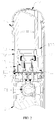
FIG. 1 is a structural diagram of a vaporization device in one embodiment of the utility. -
FIG. 2 is a diagram of a sectional structure of the vaporization device inFIG. 1 . -
FIG. 3 is a sectional diagram of a cartridge inFIG. 2 . - To clearly understand technical features, objects and effects of the utility, now detailed embodiments of the utility are explicitly explained with reference to the accompanying drawings.
- As shown in
FIGS. 1-3 , a vaporization device in one preferable embodiment of the utility comprises a cartridge 1 and abody 2. Thebody 2 comprises a power supply configured to electrically connect with the cartridge 1 and supply power to the cartridge 1. The cartridge 1 comprises a connecting end butted with thebody 2, and after the connecting end is butted with thebody 2, thebody 2 can power the cartridge 1. - The cartridge 1 comprises an
atomization base 11, and anatomization assembly 12 disposed on theatomization base 11 for heating and atomizing aerosol-generating substrate (usually a liquid), and the cartridge 1 is provided with anairflow channel 13 passing through theatomization base 11. When gas flows, an aerosol produced by theatomization assembly 12 on theatomization base 11 for heating aerosol-generating substrate is brought to asuction nozzle 14 for user drawing. - The
atomization base 11 defines at least oneventilation hole 111. Aventilation pipe 15 extends from theventilation hole 111, resulting in one end of theventilation pipe 15 extending into theairflow channel 13, and the other end being in fluid communication with apuff sensor 21 in thebody 2. Thepuff sensor 21 is a microphone arranged in thebody 2, and when thepuff sensor 21 senses a gas flowing and transmits a signal to a controller, thebody 2 is turned on to power the cartridge 1. - The
ventilation pipe 15 is disposed on theatomization base 11, and extends into theairflow channel 13 to locate above a surface of theatomization base 11, wherein the surface of theatomization base 11 defines at least a side ofairflow channel 13. That is, theventilation pipe 15 is higher than the surface of theatomization base 11. So if the cartridge 1 has a liquid leakage, it is not easy to enter into theventilation pipe 15, such that the risk of entering from theventilation pipe 15 into thebody 2 can be reduced. - The
ventilation pipe 15 is an independent component, and theventilation pipe 15 is plugged into theatomization base 11 to make production and installation simpler. Generally, theventilation pipe 15 is made of a metal material, preferably, stainless steel, which is easily formed and prevents rust. - The
ventilation pipe 15 and theatomization assembly 12 are staggered in a flow direction of theairflow channel 13, for example, theventilation pipe 15 isn't located right below theatomization assembly 12 in this embodiment, so as to avoid condensed liquid below theatomization assembly 12 from directly falling into theventilation pipe 15, to reduce the risk of the liquid flowing from theventilation pipe 15 to one side of thebody 2, and to reduce the risk of blockage of theventilation pipe 15 by the liquid, so as to improve smoothness of the airflow. - The
airflow channel 13 comprises anatomization channel 131 passing through theatomization base 11, and anair inlet channel 132 and anair outlet channel 133 respectively in communication with two ends of theatomization channel 131. When a user draws, the environment air flows sequentially through theair inlet channel 132, theatomization channel 131, and theair outlet channel 133 to thesuction nozzle 14, bringing the aerosol atomized by theatomization assembly 12 to be drawn by the user. - The
ventilation pipe 15 and theatomization assembly 12 are arranged along a flow direction of theair inlet channel 132 towards theair outlet channel 133, such that theventilation pipe 15 is on one side of theatomization base 11. Before reaching theatomization assembly 12, a part of gas flows to thebody 2 via theventilation pipe 15, to turn on thepuff sensor 21, and another part of other gas flows to theatomization assembly 12 to participate in heating and atomizing. Therefore, gas has flown to thebody 2 before reaching theatomization assembly 12, and the ventilation pipe is above theatomization base 11, so that it won't have aerosol-generating substrate flowing into theventilation pipe 15, which reduces influence of the condensate on the airflow. In this embodiment, theatomization channel 131 transversely passes through theatomization base 11, and an extending direction of theatomization channel 131 is perpendicular to an axial direction of the vaporization device. - Disposing the
ventilation pipe 15 on one side of theatomization base 11 makes airflow of the entire cartridge 1 more smooth. Disposing theventilation pipe 15 on one side of theatomization base 11 can reduce influence of the condensate on the airflow, so as to make the airflow more smooth, and have a better atomization effect. - In other embodiments, when there are a plurality of
ventilation holes 111 andventilation pipes 15, respectively, theventilation pipes 15 also can be respectively disposed on two sides of theatomization base 11, or the plurality ofventilation pipes 15 are on the same side of theatomization base 11. - The
ventilation pipe 15 is an elongated pipe. As theventilation pipe 15 is thin and long, little condensate is attached on theventilation pipe 15 because of surface tension, and does not easily enter into thebody 2. Since the ventilation pipe is thin and long, and is above a surface of theatomization base 11, when theatomization base 11 has liquid leakage, it is also not easy to enter into theventilation pipe 15 even if shaking in transportation. - In some embodiments, the
ventilation pipe 15 has an inner diameter from 0.6 mm to 1.0 mm, such as, 0.6 mm, 0.7 mm, 0.8 mm, 0.9 mm, or the like, and a length from 3 mm to 8 mm, such as, 3 mm, 4 mm, 5 mm, 6 mm, 7 mm, 8 mm, or the like. In these ranges, ventilation effect can be ensured, and liquid leakage also can be effectively prevented. - In some embodiments, the
ventilation pipe 15 is further provided with abreathable separator 151 that prevents liquid from flowing out via theventilation pipe 15. When there are more condensate, theseparator 151 can further prevent leaking liquid and condensate from flowing to thebody 2. Preferably, theseparator 151 comprises a breathable cotton or a breathable membrane disposed on one end of theventilation pipe 15 close to thebody 2, which can breathe, and also can prevent liquid from flowing. - Preferably, a gap is reserved between one end of the
ventilation pipe 15 away from theairflow channel 13 and an end surface of the connecting end, where anairflow slot 16 in communication with theventilation pipe 15 in the end surface of the connecting end is provided, to enable gas to flow to thepuff sensor 21 through theventilation pipe 15. - It shall be understood that the above respective technical features can be combined optionally for use without limitation.
- The disclosures are only embodiments of the utility, rather than limiting the extent of the utility. Any equivalent structures or equivalent flow changes using the specification and the drawings of the utility, or directly or indirectly application in other relevant technical fields shall also be included in the extent of protection of the utility.
Claims (15)
- A cartridge (1) applied to a vaporization device, the vaporization device comprises a body (2) with a power supply therein, wherein;
the cartridge (1) comprises an atomization base (11), and an airflow channel (13) passing through the atomization base (11) is arranged in the cartridge (1);
the atomization base (11) defines at least one ventilation hole (111); a ventilation pipe (15) extends from the ventilation hole (111), resulting in one end of the ventilation pipe (15) extending into the airflow channel (13), and the other end being in fluid communication with a puff sensor (21) in the body (2). - The cartridge (1) according to claim 1, characterized in that the ventilation pipe (15) is disposed on the atomization base (11), and the ventilation pipe (15) is higher than a surface of the atomization base (11).
- The cartridge (1) according to claim 1, characterized in that the cartridge (1) further comprises an atomization assembly (12) disposed on the atomization base (11) for heating and atomizing aerosol-generating substrate, and the ventilation pipe (15) and the atomization assembly (12) are staggered in a flow direction of the airflow channel (13).
- The cartridge (1) according to claim1, characterized in that the airflow channel (13) comprises an atomization channel (131) passing through the atomization base (11), and an air inlet channel (132) and an air outlet channel (133) respectively in communication with two ends of the atomization channel (131), and the ventilation pipe (15) and the atomization assembly (12) are arranged along a flow direction of the air inlet channel (132) towards the air outlet channel (133).
- The cartridge (1) according to any one of claims 1 to 4, characterized in that the ventilation pipe (15) is made of a metal material.
- The cartridge (1) according to any one of claims 1 to 4, characterized in that the ventilation pipe (15) is an elongated pipe with an inner diameter from 0.6 mm to 1.0 mm, and a length from 3 mm to 8 mm.
- The cartridge (1) according to any one of claims 1 to 4, characterized in that the ventilation pipe (15) is further provided with a breathable separator (151) that prevents liquid from flowing out via the ventilation pipe (15);
- The cartridge (1) according to any one of claims 1 to 4, characterized in that a gap is reserved between one end of the ventilation pipe (15) away from the airflow channel (13) and an end surface of the connecting end, wherein an airflow slot (16) in communication with the ventilation pipe (15) is provided in the end surface of the connecting end.
- A vaporization device, comprising:a cartridge (1) comprising an atomization base (11), and an airflow channel (13) passing through the atomization base (11) is arranged in the cartridge (1);a body (2), with a power supply configured to electrically connect with the cartridge (1) and supply power to the cartridge (1); andthe atomization base (11) defines at least one ventilation hole (111); and a ventilation pipe (15) extends from the ventilation hole (111), resulting in one end of the ventilation pipe (15) extending into the airflow channel (13), and the other end being in fluid communication with a puff sensor (21) in the body (2).
- A vaporization device according to claim 9, wherein the airflow channel (13) comprises an air inlet channel (132), an atomization channel (131) and an air outlet channel (133); wherein the environment air flows through the air inlet channel (132), the atomization channel (131) and the air outlet channel (133) when a user draws.
- A vaporization device according to claim 10, wherein
a ventilation pipe (15) is disposed on the atomization base (11), wherein one end of the ventilation pipe (15) is in fluid communication with the atomization channel (131), and the other end of the ventilation pipe (15) is in fluid communication with the puff sensor (21). - A vaporization device according to claim 10, wherein a side of the atomization channel (131) is formed by a surface of the atomization base (11), and the ventilation pipe (15) is higher than the surface of the atomization base (11).
- A vaporization device according to claim 10, characterized in that the cartridge (1) further comprises an atomization assembly (12) disposed on the atomization base (11) for heating and atomizing aerosol-generating substrate, and the ventilation pipe (15) and the atomization assembly (12) are staggered in a flow direction of the airflow channel (13).
- A vaporization device according to any one of claims 9 to 13, characterized in that the ventilation pipe (15) is made of a metal material.
- A vaporization device according to any one of claims 9 to 13, characterized in that the ventilation pipe (15) is further provided with a breathable separator (151) that prevents liquid from flowing out via the ventilation pipe (15).
Applications Claiming Priority (1)
| Application Number | Priority Date | Filing Date | Title |
|---|---|---|---|
| CN201821501635.XU CN209031257U (en) | 2018-09-13 | 2018-09-13 | Electronic cigarette and its atomising device |
Publications (1)
| Publication Number | Publication Date |
|---|---|
| EP3626088A1 true EP3626088A1 (en) | 2020-03-25 |
Family
ID=67033146
Family Applications (1)
| Application Number | Title | Priority Date | Filing Date |
|---|---|---|---|
| EP19197173.8A Pending EP3626088A1 (en) | 2018-09-13 | 2019-09-13 | Vaporization device and cartridge thereof |
Country Status (2)
| Country | Link |
|---|---|
| EP (1) | EP3626088A1 (en) |
| CN (1) | CN209031257U (en) |
Cited By (1)
| Publication number | Priority date | Publication date | Assignee | Title |
|---|---|---|---|---|
| US12550942B2 (en) | 2022-09-19 | 2026-02-17 | Altria Client Services Llc | Session control system |
Families Citing this family (6)
| Publication number | Priority date | Publication date | Assignee | Title |
|---|---|---|---|---|
| CN111602859A (en) * | 2019-06-29 | 2020-09-01 | 深圳市艾维普思科技有限公司 | an electronic cigarette |
| US20220248766A1 (en) * | 2019-07-08 | 2022-08-11 | O-Net Automation Technology (Shenzhen) Limited | Electronic cigarette and airflow switch bracket, airflow switch assembly and power supply apparatus thereof |
| CN110613170A (en) * | 2019-09-29 | 2019-12-27 | 深圳麦克韦尔科技有限公司 | Electronic atomization device and atomizer thereof |
| CN212814261U (en) * | 2020-05-09 | 2021-03-30 | 深圳麦克韦尔科技有限公司 | Electronic atomization device and atomizer thereof |
| EP4166017A4 (en) * | 2020-08-25 | 2023-07-19 | Shenzhen Smoore Technology Limited | ELECTRONIC ATOMIZING DEVICE |
| CN112315029B (en) * | 2020-11-13 | 2025-12-05 | 深圳九脉科技有限公司 | A high-efficiency oil leak prevention cartridge |
Citations (3)
| Publication number | Priority date | Publication date | Assignee | Title |
|---|---|---|---|---|
| US20170042229A1 (en) * | 2014-02-12 | 2017-02-16 | Kimree Hi-Tech Inc. | Electronic cigarette |
| US20170119055A1 (en) * | 2014-04-02 | 2017-05-04 | Kimree Hi-Tech Inc. | Atomization assembly and electronic cigarette |
| CN107536110A (en) * | 2017-04-21 | 2018-01-05 | 深圳市卓力能电子有限公司 | A kind of electronic cigarette |
-
2018
- 2018-09-13 CN CN201821501635.XU patent/CN209031257U/en active Active
-
2019
- 2019-09-13 EP EP19197173.8A patent/EP3626088A1/en active Pending
Patent Citations (3)
| Publication number | Priority date | Publication date | Assignee | Title |
|---|---|---|---|---|
| US20170042229A1 (en) * | 2014-02-12 | 2017-02-16 | Kimree Hi-Tech Inc. | Electronic cigarette |
| US20170119055A1 (en) * | 2014-04-02 | 2017-05-04 | Kimree Hi-Tech Inc. | Atomization assembly and electronic cigarette |
| CN107536110A (en) * | 2017-04-21 | 2018-01-05 | 深圳市卓力能电子有限公司 | A kind of electronic cigarette |
Cited By (1)
| Publication number | Priority date | Publication date | Assignee | Title |
|---|---|---|---|---|
| US12550942B2 (en) | 2022-09-19 | 2026-02-17 | Altria Client Services Llc | Session control system |
Also Published As
| Publication number | Publication date |
|---|---|
| CN209031257U (en) | 2019-06-28 |
Similar Documents
| Publication | Publication Date | Title |
|---|---|---|
| CN112263020B (en) | Electronic atomization device and battery device for same | |
| CN207383537U (en) | A kind of ultrasonic wave liquid electronic smoke atomizer and ultrasonic wave liquid electronic cigarette | |
| AU2016240554B2 (en) | Flavor inhaler | |
| US11375750B2 (en) | Atomizer and electronic cigarette thereof | |
| CN112189897B (en) | Atomizer and electronic atomization device thereof | |
| CN206119177U (en) | Cavity leak protection electronics smog core | |
| CN206197020U (en) | A kind of unilateral hollow electronic cigarette atomizing core | |
| WO2021031891A1 (en) | Electronic cigarette atomizing core and atomizer | |
| CN209031257U (en) | Electronic cigarette and its atomising device | |
| CN217446690U (en) | Atomizer and aerosol generating device | |
| WO2022022172A1 (en) | E-liquid condensate water preventing mechanism and aerosol generating device | |
| US20240306721A1 (en) | Aerosol generation article and aerosol generation apparatus | |
| CN218354595U (en) | Atomizer and electronic atomization device | |
| CN204466909U (en) | Inhalator and atomizing component thereof and liquid storage pipe | |
| CN206119185U (en) | Atomizer and electron cigarette thereof | |
| CN221576853U (en) | Atomization device | |
| WO2020093746A1 (en) | Disposable atomiser apparatus for electronic cigarette | |
| CN207383532U (en) | Electronic cigarette and its atomizing component | |
| CN209628644U (en) | Ceramic electronic vaporizer | |
| CN217471238U (en) | A kind of atomization component and electronic atomization device | |
| CN207040891U (en) | Atomizer and electronic cigarette with circulating type gas channel | |
| CN210094687U (en) | new atomizer | |
| CN205125040U (en) | Device that generates heat, atomising head and electron cigarette of electron smog spinning disk atomiser | |
| WO2021142740A1 (en) | Electronic cigarette atomizer and electronic cigarette | |
| CN220859431U (en) | Atomizer core assembly, atomizer and atomizer device |
Legal Events
| Date | Code | Title | Description |
|---|---|---|---|
| PUAI | Public reference made under article 153(3) epc to a published international application that has entered the european phase |
Free format text: ORIGINAL CODE: 0009012 |
|
| STAA | Information on the status of an ep patent application or granted ep patent |
Free format text: STATUS: THE APPLICATION HAS BEEN PUBLISHED |
|
| AK | Designated contracting states |
Kind code of ref document: A1 Designated state(s): AL AT BE BG CH CY CZ DE DK EE ES FI FR GB GR HR HU IE IS IT LI LT LU LV MC MK MT NL NO PL PT RO RS SE SI SK SM TR |
|
| AX | Request for extension of the european patent |
Extension state: BA ME |
|
| STAA | Information on the status of an ep patent application or granted ep patent |
Free format text: STATUS: REQUEST FOR EXAMINATION WAS MADE |
|
| 17P | Request for examination filed |
Effective date: 20200921 |
|
| RBV | Designated contracting states (corrected) |
Designated state(s): AL AT BE BG CH CY CZ DE DK EE ES FI FR GB GR HR HU IE IS IT LI LT LU LV MC MK MT NL NO PL PT RO RS SE SI SK SM TR |
|
| STAA | Information on the status of an ep patent application or granted ep patent |
Free format text: STATUS: EXAMINATION IS IN PROGRESS |
|
| 17Q | First examination report despatched |
Effective date: 20221024 |
|
| RAP3 | Party data changed (applicant data changed or rights of an application transferred) |
Owner name: SHENZHEN SMOORE TECHNOLOGY LIMITED |
|
| RAP3 | Party data changed (applicant data changed or rights of an application transferred) |
Owner name: SHENZHEN SMOORE TECHNOLOGY LIMITED |