EP3626075A1 - Fishing reel and magnetic seal device therefor - Google Patents
Fishing reel and magnetic seal device therefor Download PDFInfo
- Publication number
- EP3626075A1 EP3626075A1 EP19207302.1A EP19207302A EP3626075A1 EP 3626075 A1 EP3626075 A1 EP 3626075A1 EP 19207302 A EP19207302 A EP 19207302A EP 3626075 A1 EP3626075 A1 EP 3626075A1
- Authority
- EP
- European Patent Office
- Prior art keywords
- magnetic
- magnetic plate
- housing part
- seal device
- plate
- Prior art date
- Legal status (The legal status is an assumption and is not a legal conclusion. Google has not performed a legal analysis and makes no representation as to the accuracy of the status listed.)
- Granted
Links
Images



Classifications
-
- A—HUMAN NECESSITIES
- A01—AGRICULTURE; FORESTRY; ANIMAL HUSBANDRY; HUNTING; TRAPPING; FISHING
- A01K—ANIMAL HUSBANDRY; AVICULTURE; APICULTURE; PISCICULTURE; FISHING; REARING OR BREEDING ANIMALS, NOT OTHERWISE PROVIDED FOR; NEW BREEDS OF ANIMALS
- A01K89/00—Reels
- A01K89/01—Reels with pick-up, i.e. with the guiding member rotating and the spool not rotating during normal retrieval of the line
- A01K89/01121—Frame details
- A01K89/011221—Frame details with line or water shields
-
- A—HUMAN NECESSITIES
- A01—AGRICULTURE; FORESTRY; ANIMAL HUSBANDRY; HUNTING; TRAPPING; FISHING
- A01K—ANIMAL HUSBANDRY; AVICULTURE; APICULTURE; PISCICULTURE; FISHING; REARING OR BREEDING ANIMALS, NOT OTHERWISE PROVIDED FOR; NEW BREEDS OF ANIMALS
- A01K89/00—Reels
- A01K89/01—Reels with pick-up, i.e. with the guiding member rotating and the spool not rotating during normal retrieval of the line
-
- A—HUMAN NECESSITIES
- A01—AGRICULTURE; FORESTRY; ANIMAL HUSBANDRY; HUNTING; TRAPPING; FISHING
- A01K—ANIMAL HUSBANDRY; AVICULTURE; APICULTURE; PISCICULTURE; FISHING; REARING OR BREEDING ANIMALS, NOT OTHERWISE PROVIDED FOR; NEW BREEDS OF ANIMALS
- A01K89/00—Reels
- A01K89/01—Reels with pick-up, i.e. with the guiding member rotating and the spool not rotating during normal retrieval of the line
- A01K89/0117—Anti-reverse mechanisms
-
- A—HUMAN NECESSITIES
- A01—AGRICULTURE; FORESTRY; ANIMAL HUSBANDRY; HUNTING; TRAPPING; FISHING
- A01K—ANIMAL HUSBANDRY; AVICULTURE; APICULTURE; PISCICULTURE; FISHING; REARING OR BREEDING ANIMALS, NOT OTHERWISE PROVIDED FOR; NEW BREEDS OF ANIMALS
- A01K89/00—Reels
- A01K89/015—Reels with a rotary drum, i.e. with a rotating spool
-
- A—HUMAN NECESSITIES
- A01—AGRICULTURE; FORESTRY; ANIMAL HUSBANDRY; HUNTING; TRAPPING; FISHING
- A01K—ANIMAL HUSBANDRY; AVICULTURE; APICULTURE; PISCICULTURE; FISHING; REARING OR BREEDING ANIMALS, NOT OTHERWISE PROVIDED FOR; NEW BREEDS OF ANIMALS
- A01K89/00—Reels
- A01K89/015—Reels with a rotary drum, i.e. with a rotating spool
- A01K89/0192—Frame details
- A01K89/01928—Frame details with line or water shields
Definitions
- the first magnetic plate includes a second hole defined therein and the cover member includes at least one protrusion extending from a front surface thereof that is received in the second hole.
- the second hole is open to an exterior diameter of the first magnetic plate.
- the one-way clutch 5 is secured in the housing part 4 by a cover member 6.
- the cover member 6 covers the front side of the housing part 4 excluding the rotation part comprising the pinion gear 3 and the boss part which is fitted to the pinion gear 3 of the rotor 11.
- the cover member 6 is fixed so that it does not contact the rotation part.
Landscapes
- Life Sciences & Earth Sciences (AREA)
- Environmental Sciences (AREA)
- Animal Husbandry (AREA)
- Biodiversity & Conservation Biology (AREA)
- Sealing Using Fluids, Sealing Without Contact, And Removal Of Oil (AREA)
Abstract
Description
- The said invention relates to a fishing reel and a magnetic seal device used for fishing reels.
- Fishing reels are often used in harsh and severe environments where water can inundate the reel. In order to prevent inundation at a driving member which is provided in a housing part of the fishing reel, and to always ensure stable driving performance in a harsh environment, a seal device is provided at the driving member. For example, reference is made to
JP 2010 - 187 566 A JP 2011 - 167 186 A - The fishing reel in accordance with the present invention provides a reel body, a driving member which is supported by the reel body so that it can rotate, a housing part which protrudes the driving member from the opening part, partly houses the driving member and is fitted to the reel body, and a magnetic seal device which seals a gap between the housing part and the driving member at the opening part of the housing part. The magnetic seal device includes a magnet, first and second magnetic plates which maintain the magnet, the first magnetic plate is located adjacent the housing part and the second magnetic plate is located on an opposite side of the housing part of the magnet, and a magnetic fluid which is maintained at the gap between the driving member and at least one of the first magnetic plate and the second magnetic plate. Then, the exterior diameter of the surface of the internal side, which joins the edge of the opening part periphery of the housing part of the magnetic seal device that includes the first magnetic plate, the magnet and the second magnetic plate.
- It is preferable that the exterior diameter of the first magnetic plate is larger than that of the second magnetic plate. It is preferable that there are further fixing components which fix the magnetic plate of the magnetic seal device to the housing part. It is preferable that a hole which extends through the fixing component is formed with one of the larger exterior diameters of the first magnetic plate and the second magnetic plate. It is preferable that the fixing component be a screw which has a screw part and a screw head, and a height from the magnet side surface of the first magnetic plate to the opposite side surface of the second magnetic plate is larger than a height of the screw head.
- The magnetic seal device used for the fishing reel, in accordance with a second aspect of the invention seals a gap between the driving member and the housing part. The housing part is fixed to the reel body and at least partially accommodates the driving member extending through the opening of the housing part. The magnetic seal device is comprised of a magnet, a first magnetic plate and a second magnetic plate which maintain the magnet therebetween, and a magnetic fluid which is maintained at the gap between the driving member and at least one of the first magnetic plate and the second magnetic plate. Then, an exterior diameter of the internal side surface of the magnetic seal device which joins the edge of the opening parts periphery of the housing part which is larger than an exterior diameter of the external side surface of the magnetic seal device. A hole which extends through the fixing component in order to fix the magnetic seal device to the housing part is formed at the one of larger exterior diameters of the first magnetic plate and the second magnetic plate.
- In accordance with the invention, it is unnecessary to form a segment at the edge of the housing part in order to install the magnetic seal device. As a result, the structure of the opening part which is sealed at the magnetic seal device is simple and easy to process.
- In accordance with another aspect of the invention there is provided a fishing reel that includes a reel body, a housing part that at least partially accommodates the driving member extending through an opening part thereof, and a magnetic seal device that seals a gap between the housing part and the driving member. The magnetic seal device includes a magnet, a first magnetic plate and a second magnetic plate that maintain the magnet therebetween, and a magnetic fluid maintained at a gap between the driving member and at least one of the first magnetic plate and the second magnetic plate. An external diameter of the housing part is larger than the external diameter of the magnetic seal device. In a preferred embodiment, the first magnetic plate is located adjacent the housing part and the second magnetic plate is located on an opposite side of the housing part of the magnet, and the external diameter of the first magnetic plate is larger than an external diameter of the second magnetic plate. Preferably, the reel includes a fixing component that fixes the magnetic seal device to the housing part. In a preferred embodiment, a hole is formed in one of the first magnetic plate or the second magnetic plate and the fixing component is received in the hole. Preferably, the fixing component is a screw that includes a screw part and a screw head. The first and second magnetic plates each include a front surface. A distance from the front surface of the first magnetic plate to the front surface of the second magnetic plate is preferably larger than a height of the screw head.
- In accordance with another aspect of the invention there is provided a fishing reel that includes a reel body, a housing part that defines an opening part, a driving member that includes a pinion that is supported by the reel body and extends through the opening part of the housing part, and a magnetic seal device that is affixed to the housing part and includes a central opening through which the pinion extends. The magnetic seal device includes first and second magnetic plates that maintain a magnet therebetween and a magnetic fluid that is maintained at a gap between the driving member and at least one of the first and second magnetic plates. In a preferred embodiment, the housing part includes a cover member and the first magnetic plate is attached to a front surface of the cover member. Preferably, the cover member has an outer diameter that is larger than an outer diameter of the magnetic seal device.
- In a preferred embodiment, one of the first and second magnetic plates has an outer diameter that is larger than the other of the first and second magnetic plates. Preferably, it is the first magnetic plate that has the larger outer diameter and a first hole is formed in the first magnetic plate. A fixing component extends through the first hole to attach the first magnetic plate to the cover member. Preferably, the fixing component is a screw that includes a screw part and a screw head and the first and second magnetic plates each include a front surface. A distance from the front surface of the first magnetic plate to the front surface of the second magnetic plate is larger than a height of the screw head.
- In a preferred embodiment, the reel further comprises a rotor that includes a cylinder part, a wall part and a boss part and the boss part is at least partially received in the central opening of the magnetic seal device. Preferably a magnetic body at least partially surrounds the boss part and the magnetic fluid is maintained between the magnetic body and at least one of the first and second magnetic plates.
- In a preferred embodiment, the first magnetic plate includes a second hole defined therein and the cover member includes at least one protrusion extending from a front surface thereof that is received in the second hole. Preferably, the second hole is open to an exterior diameter of the first magnetic plate.
- In accordance with another aspect of the invention there is provided a magnetic seal device that includes first and second magnetic plates that maintain a magnet therebetween. The first magnetic plate has an outer diameter that is larger than the second magnetic plate, at least one of the first holes is formed in the first magnetic plate, and a fixing component extends through the first hole and is adapted to attach the first magnetic plate to a cover member.
- The invention, together with additional features and advantages thereof, may be best understood by reference to the following description.
- Selected embodiments of the present invention will now be explained with reference to the drawings, wherein
- FIG. 1
- is a sectional view of the fishing reel in accordance with an embodiment of the invention.
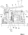
- FIG. 2
- is a sectional view of the magnetic seal device part in accordance with the embodiment.
- FIG. 3
- is a sectional view taken along line A-A of
FIG. 2 . - FIG. 4
- is an oblique view of the magnetic seal device in accordance with the embodiment.
- FIG. 5
- is a sectional view of the magnetic seal device part in accordance with a variant embodiment.
- Like numerals refer to like parts throughout the several views of the drawings. It will be apparent to those skilled in the art from this disclosure that the following descriptions of the embodiments are provided for illustration only and not for the purpose of limiting the invention as defined by the appended claims and their equivalents.
- The terms such as "front," "back," "top," "bottom," "side," "short," "long," "up," "down," "left," "right" and "below" used herein are merely for ease of description and refer to the orientation of the components as shown in the figures. It should be understood that any orientation of the components described herein is within the scope of the present invention.
-
FIG. 1 is a sectional view of a fishing reel in accordance with an embodiment of the invention. The embodiment takes thespinning reel 100 of the fishing reel as an objective. Thespinning reel 100 is installed on a fishing rod in such a way that the left direction faces the front end (foreside) of the fishing rod when viewingFIG. 1 . Thespinning reel 100 includes areel body 1, arotor 11, aspool 12 and ahandle 13. Fishing line (not illustrated), which is wound around thespool 12, is casted out forward, i.e., in the left direction ofFIG. 1 . - The
rotor 11 rotates around a central shaft which extends in the forward/backward direction, i.e., in the left/right direction ofFIG. 1 , by rotating thehandle 13 which serves as a crank. Once thehandle 13 is rotated, thespool 12 moves to-and-fro in the forward/backward direction at the same time as the rotation of therotor 11. In accordance with its movement, the fishing line which has been let out is guided by therotor 11 and uniformly wound to the bobbin trunk of thespool 12. - The
rotor 11 is fixed to a fixingpart 32 of apinion gear 3 and rotates together with thepinion gear 3. Thepinion gear 3 is rotatably supported by thereel body 1 so that it can rotate. Thepinion gear 3 is formed as like a cylindrical shape, and aspool shaft 2 extends through thepinion gear 3. Thespool shaft 2 and thepinion gear 3 can rotate and can move to-and-fro relatively. Thespool 12 is installed on the front end of thespool shaft 2 via the drag mechanism. The rear end side of thespool shaft 2 is connected to theoscillating mechanism 15. - The
handle 13 is the crank and adriving gear 14 is installed at the crank shaft. Thedriving gear 14 is engaged with agear part 31 of thepinion gear 3, for example, by a bevel gear. Theoscillating mechanism 15 rotates simultaneously with thepinion gear 3. Once theoscillating mechanism 15 rotates, thespool shaft 2 is moved to-and-fro in the forward/backward direction. The rear end side of thespool shaft 2, thegear part 31 side of thepinion gear 3, thedriving gear 14 and theoscillating mechanism 15 are housed by thereel body 1. - A one-
way clutch 5 is located between thepinion gear 3 and ahousing part 4 so that thepinion gear 3 rotates in a unidirectional way only. Thehousing part 4 is fixed to the reel body. An inner side of the one-way clutch 5 is fitted to thepinion gear 3 and rotates together with thepinion gear 3. An outer side of the one-way clutch 5 is fitted and fixed to thehousing part 4. - The one-
way clutch 5 is, for example, a roller-type one-way clutch. The roller-type one-way clutch comprises an outer race, an inner race, rollers and springs. The cam surface is formed on the internal periphery of the outer race or the external periphery of the inner race. The roller is located opposite to the cam surface and is kept to join the cam surface of the outer race and the external periphery of the inner race or the cam surface of the inner race and the internal periphery due to the spring. Once the inner race is to rotate in a unidirectional way against the outer race, the contact pressure between the cam surface and the roller becomes high and causes resistance, so the inner race does not rotate against the outer race. Once the inner race rotates in the opposite direction, the contact pressure between the cam surface and the roller becomes low, so the roller idles and the inner race rotates against the outer race. As a result, thepinion gear 3 rotates in a unidirectional way only. - The one-
way clutch 5 is secured in thehousing part 4 by acover member 6. Thecover member 6 covers the front side of thehousing part 4 excluding the rotation part comprising thepinion gear 3 and the boss part which is fitted to thepinion gear 3 of therotor 11. Thecover member 6 is fixed so that it does not contact the rotation part. - In order to seal a gap between the
cover member 6 and the boss part of therotor 11 together, a magnetic seal device which contains a ring-shapedmagnet 8, andmagnetic plates magnetic body 7 is formed around the external periphery of the boss part in its rotation direction. The ring-shapedmagnetic body 7 is, thus, fitted to thepinion 3 as will be explained below in more detail. Themagnetic body 7 and themagnet 8 are opposite to themagnetic plates magnetic body 7 and themagnet 8 and themagnetic plates magnet 8,magnetic plates magnetic body 7.Magnetic fluid 10 is disposed and maintained between themagnetic body 7 and themagnetic plates cover member 6 and the magnetic body 7 (boss part) are sealed together. - The driving member is supported by the
reel body 1 so that it can rotate. In this embodiment, the driving member comprises thepinion gear 3 that protrudes through thecover member 6 and thehousing part 4. The boss part and themagnetic body 7 form the opening part in thehousing part 4 which partly houses thepinion gear 3. Thecover member 6 and thehousing part 4 are fixed against thereel body 1. The magnetic seal device seals a gap between the housing part and the driving member together at the opening part of the housing part. -
FIG. 2 is a sectional view of the magnetic seal device in accordance with the embodiment.FIG. 2 only shows the lateral side against the central line of thespool shaft 2. - The
rotor 11 comprises acylinder part 111, awall part 112 and theboss part 113. These are formed integrally by one component. Thecylinder part 111 is a cylinder-shaped component and has housing room (accommodating room) inside itself. The external periphery of thewall part 112 is connected to the internal periphery of thecylinder part 111. Theboss part 113 extends to the one-way clutch 5 from the internal periphery end of thewall part 112. Theboss part 113 is fitted and fixed to the fixingpart 32 of thepinion gear 3 while therotor 11 rotates together with thepinion gear 3. - The
housing part 4 is fixed by, for example, a screw so that it does not rotate against thereel body 1 in front of thereel body 1. The one-way clutch 5 is housed and accommodated inside thehousing part 4. Thecover member 6 is a ring-shaped component comprising a cylinder part which covers the external periphery of thehousing part 4 and thecover member 6 covers the front side of thehousing part 4. Thecover member 6 keeps the one-way clutch 5 inside thehousing part 4 through thecover member 6. Thecover member 6 is fixed to thehousing part 4 and, thus, to thereel body 1 by, for example, thescrew 91. Aring seal 17 is located between the end part of the cylinder part of thecover member 6 and thereel body 1. The internal periphery of thecover member 6 is opposite to and has an interval gap from the external periphery of themagnetic body 7. - The
magnetic body 7 is formed in a ring shape around the external periphery of theboss part 113 in its rotation direction and is fitted to theboss part 113. In the example illustrated inFIG. 2 , themagnetic body 7 contains a ring plate shaped part which joins the external periphery of thepinion gear 3. The inside of themagnetic body 7 is fitted to thepinion gear 3 while the external periphery of themagnetic body 7 is defined by themagnetic body 7 and the engagement between themagnetic body 7 and thepinion gear 3. - The
magnet 8 is located at radially outside of themagnetic body 7 and has a radial gap from themagnetic body 7. Themagnet 8 is formed in a ring shape. Additionally, themagnetic plates magnetic body 7 and have a gap from themagnetic body 7. The magnetic plates jointly form a ring around the radially external periphery of themagnetic body 7 and are radially outside themagnetic body 7. Themagnetic plates magnet 8 in the direction of the driving member. The external diameter of themagnetic plate 9a which is located on the housing part side of themagnet 8 is larger than the external diameter of themagnetic plate 9b which is located on the opposite side of thelid part 6 of themagnet 8. - The
magnet 8, themagnetic plate 9a and themagnetic plate 9b are fixed to each other by, for example, adhesive agent to form the magnetic seal device. Themagnetic plate 9a is connected to thecover member 6 and, thus, to thehousing part 4 by a fixing component, for example, thescrew 91. The magnetic seal device is fixed to thecover member 6. Thescrew 91 has the screw part which is screwed in the screw hole formed at thecover member 6 and the screw head which presses themagnetic plate 9a. At least twoscrews 91 are located on the circumference with the central shaft of thepinion gear 3 as the center with equal interval. The edge surface on therotor 11 side of thecover member 6 is a plane surface. - There is a gap between the
magnet 8, the internal periphery of themagnetic plates magnetic body 7. Themagnetic fluid 10 is located at the gap. Themagnet 8, themagnetic plates magnetic fluid 10 constitute the magnetic seal device. - The magnetic circuit is formed by the
magnet 8, themagnetic plate 9a, themagnetic body 7 and themagnetic plate 9b. Themagnetic fluid 10 is a substance which stably disperses the micro-particle of strong magnetic substance with a particle diameter ranging from a few nm to more than ten nm into, for example, hydrocarbon oil or fluorine grease based solution by using surfactant. Because the part opposite to themagnet 8 and themagnetic plates magnetic body 7 is magnetized, themagnetic fluid 10 is kept in the realm surrounded by themagnet 8, themagnetic plates magnetic body 7. The gap between themagnet 8, themagnetic plates magnetic body 7 is sealed by themagnetic fluid 10 to prevent foreign substances from infiltrating from the housing room of thecylinder part 111 to the one-way clutch 5 side. Because the magnetic seal mechanism surrounds the periphery of themagnetic body 7 with liquid, it is airtight. Additionally, because there is no solid contact at the seal part, no dust is created. Because there is no movement at the sealing part, the loss of torque is small and the rotation performance is not declined. - Although the
magnetic fluid 10 fills the whole realm surrounded by themagnet 8, themagnetic plates magnetic body 7 inFIG. 2 , the magnetic fluid can also be maintained between themagnetic plate 9a and themagnetic body 7 or between themagnetic plate 9b and themagnetic body 7 only. Additionally, if the internal periphery of themagnet 8 is enlarged a little, themagnetic fluid 10 can also be maintained at two parts, i.e., between themagnetic plate 9a and themagnetic body 7 and between themagnetic plate 9a and themagnetic body 7. - Because the magnetic force line of the
magnet 8 is drawn near to themagnetic plates magnetic body 7 and passes in the middle, the magnetism of themagnet 8 is not leaked on the one-way clutch 5 side. Therefore, theinner race 51 of the one-way clutch 5 is not magnetized and themagnet 8 does not influence the movement of the one-way clutch 5. As a result, in accordance with this embodiment, it is easy to assemble and the watertight performance can be maintained without deteriorating the performance of the one-way clutch 5. - Because the external diameter of the
magnetic plate 9a is larger than the external diameter of themagnetic plate 9b and themagnetic plate 9a is installed at the edge surface of thecover member 6, it is unnecessary to form a segment part at the edge surface of thecover member 6 and the edge surface can be made a plane surface. As a result, it is easy to process thecover member 6. Additionally, because themagnet 8 and themagnetic plate 9b are fixed on the opposite side of the housing part side of themagnetic plate 9a, if the height of the screw head of thescrew 91 which connects themagnetic plate 9a is limited within the range of the thickness of themagnet 8 and themagnetic plate 9b, the part protruding from the magnetic seal device to thewall part 112 side of therotor 11 can be eliminated. - Although the shape of a pan head screw is described in
FIG. 2 , thescrew 91 is not limited to the shape inFIG. 2 . For example, a truss screw, oval head screw or a low head screw can also be used.FIG. 3 is a sectional view taken along line A-A ofFIG. 2 . In accordance with the example inFIG. 3 , threescrews 91 are located on the circumference with the central shaft of thepinion gear 3 as the center with equal intervals. Ahole 92, which is fitted to aprotrusion 61 of the cover member, is formed at two locations on the external periphery of themagnetic plate 9a. The gap between the magnetic seal device and themagnetic body 6 are positioned equally at the position where twoprotrusions 61 and twoholes 92 are fitted, respectively. In accordance with the example inFIG. 3 , thehole 92 is formed in U-shape which is cut from the external periphery of themagnetic plate 9a. Theprotrusion 61 and thehole 92 are formed at a position that does not interfere with thescrew 91. -
FIG. 4 is an oblique view of the magnetic seal device in accordance with the embodiment. Thescrew 91 is shown by a two-dot chain line. Although only onescrew 91 is described inFIG. 4 (in order to avoid complication) there are actually threescrews 91 as shown inFIG. 3 . Ahole 93 through which thescrew 91 passes is formed in themagnetic plate 9a. Although one of thescrews 93 is hidden at the magnetic plate and cannot be seen, threeholes 93 are formed. As stated above, thescrew 91 has thescrew part 91a and thescrew head 91b. The height from the surface on themagnet 8 side of themagnetic plate 9a (the first magnetic plate) to the surface opposite to themagnet 8 of themagnetic plate 9b (the second magnetic plate) is larger than the height of thescrew head 91b. - Regarding the shape of the
magnetic plate 9a and themagnetic plate 9b inFIG. 2 , in other words, the external diameter of the internal side surface which joins the edge surface of the opening part periphery of the cover member 6 (the housing part) of the magnetic seal device which comprises themagnetic plate 9a (the first magnetic plate), themagnet 8 and themagnetic plate 9b (the second magnetic plate) is larger than the external diameter of the outside surface of the magnetic seal device. If it is constituted in this way, the relation between themagnetic plate 9a and themagnetic plate 9b is not limited to the example inFIG. 2 . -
FIG. 5 is a sectional view of a magnetic seal mechanism part in accordance with a variant example. In the variant example inFIG. 5 , themagnet 8 is maintained by amagnetic plate 9c and amagnetic plate 9d. Themagnetic plate 9d (the second magnetic plate) which is located on the opposite side of thecover member 6 of themagnet 8 is of a shape with a level difference formed by a concave part at the center. Themagnet 8 and themagnetic plate 9c are embedded into the concave part of themagnetic plate 9d. The depth of the concave part of themagnetic plate 9d is almost the same as the thickness of themagnet 8 and themagnetic plate 9c. Once themagnet 8 and themagnetic plate 9c are embedded into the concave part of themagnetic plate 9d, themagnetic plate 9d and the magnetic 9c become almost co-planar. - Likewise in accordance with the variant example, the
magnetic plate 9c and themagnetic plate 9d are fixed mutually by, for example, an adhesive agent to form the magnetic seal device. In the variant example, themagnetic plate 9d is connected to thecover member 6 and, thus, to thehousing part 4 by, for example, thescrew 91 and the magnetic seal device is fixed to thecover member 6. At least twoscrews 91 are located on the circumference with the central shaft of thepinion gear 3 as the center with equal interval. The edge surface on therotor 11 side of thecover member 6 is a plane surface. - Likewise, in accordance with the variant example, the external diameter of the inside surface which joins the edge surface of the opening part periphery of the cover member 6 (the housing part) of the magnetic seal device which comprises the
magnetic plate 9c (the first magnetic plate), themagnet 8 and themagnetic plate 9d (the second magnetic plate) is larger than the external diameter of the outside surface of the magnetic seal device. Then, it is unnecessary to form the segment part on the edge surface of thecover member 6 and the edge surface can be made plane surface. As a result, thecover member 6 can be easily processed. - In the variant example, the
hole 93 which passes thescrew 91 is formed in themagnetic plate 9d. That is to say, thehole 93 which passes the fixing component is formed at the one of larger portions of the first magnetic plate and the second magnetic plate. The height from the surface on themagnet 8 side of themagnetic plate 9c (the first magnetic plate) to the surface on the opposite side of themagnet 8 of themagnetic plate 9d (the second magnetic plate) is larger than the height of thescrew head 91b. Because themagnet 8 and themagnetic plate 9d are fixed on the opposite side of thecover member 6 of themagnetic plate 9c, if the height of the screw head of thescrew 91 which connects themagnetic plate 9d is limited to the range of the thickness of themagnet 8 and themagnetic plate 9d, the part protruding from the magnetic seal device to thewall part 112 side of therotor 11 can be deleted. - In the variant example, although it is necessary to form the concave part at the
magnetic plate 9d, the interface between themagnetic plate 9d and themagnet 8 and the surface between themagnet 8 and themagnetic plate 9c are covered and protected by themagnetic plate 9d. Additionally, the concave part of themagnetic plate 9d can be formed through, for example, drawing press processing. - Likewise in the variant example, as shown in
FIG. 3 , thehole 92 where theprotrusion 61 of thecover member 6 is fitted can be formed on the inside surface of the magnetic seal device which joins the edge surface of the opening part periphery of the cover member. If the protrusion approaches the external periphery, thehole 92 is formed at themagnetic plate 9d. - In the variant example, the boss part of the
rotor 11 and themagnet 7 are different in constitution. Theboss part 113 is formed by magnetic material while themagnetic body 7 is formed integrally with theboss part 113. Therotor 11 is formed by thecylinder part 111 and thewall part 112 integrally while theboss part 113 is formed by another component. The internal periphery part of thewall part 112 is fixed to theboss part 113 and forms therotor 11. Thewall part 112 is fixed to theboss part 113 by, for example, strong pressing, caulking, adhesion or screw clamp. Other constitutions are same as inFIG. 2 . - Likewise in the variant example, because the magnetic force line of the
magnet 8 is drawn near to themagnetic plates boss part 113 and passes in the middle, the magnetism of themagnet 8 is not leaked on the one-way clutch 5 side. Therefore, theinner race 51 of the one-way clutch 5 is not magnetized and themagnet 8 does not influence the movement of the one-way clutch 5. As a result, like in the above example, it is easy to assemble and the stable watertight performance can be maintained without deteriorating the performance of the one-way clutch 5. - In the variant example, because the external periphery surface of the magnetic body 7 (the boss part 113) opposite to the
magnet 8 and themagnetic plates boss part 113 and thepinion gear 3, the precision of the gap between themagnetic plate - In the embodiment, although the constitution where the one-
way clutch 5 which is fitted to thepinion gear 3 which drives therotor 11 of the spinningreel 100 is sealed by the magnetic seal device has been described, the magnetic seal device of the fishing reel is not limited to the example. It also applies that the magnetic seal device which seals the opening part of the housing part which protrudes the driving member from the opening and partly houses the driving member is installed from the protruding side of the driving member to the housing part. - Additionally, the magnetic circuit formed opposite to the magnet and the magnetic plate is not limited to the
magnetic body 7 inFIG. 2 and theboss part 113 inFIG. 5 . For example, in case that thepinion gear 3 is formed by a magnetic body, the magnetic fluid can be located between thepinion gear 3 and the magnetic plate. - In understanding the scope of the present invention, the term "comprising" and its derivatives, as used herein, are intended to be open ended terms that specify the presence of the stated features, elements, components, groups, integers, and/or steps, but do not exclude the presence of other unstated features, elements, components, groups, integers and/or steps. The foregoing also applies to words having similar meanings such as the terms, "including," "having" and their derivatives. Moreover, in the scope of the present invention, the term "mounted" or "mounting," as used herein, encompasses configurations in which an element directly secured to another element by affixing the element is directly to the other element; configurations in which the element is indirectly secured to the other element by affixing the element to the intermediate member(s) which in turn are affixed to the other element; and configurations in which one element is integral with another element, i.e. one element is essentially part of the other element. This definition also applies to words of similar meaning, for example, "joined", "connected", "coupled", "attached", "bonded", "fixed" and their derivatives. Also, the terms "part," "section," "portion," "member" or "element" when used in the singular can have the dual meaning of a single part or a plurality of parts. Finally, terms of degree such as "substantially," "about" and "approximately" as used herein mean a reasonable amount of deviation of the modified term such that the end result is not significantly changed.
- Although exemplary embodiments of the invention have been shown and described, it is to be understood that all the terms used herein are descriptive rather than limiting, and that many changes, modifications, and substitutions may be made by one having ordinary skill in the art without departing from the spirit and scope of the invention.
Claims (9)
- A fishing reel (100) comprising:a reel body (1),a driving member rotatably supported on the reel body (1) and including a pinion gear (3), the pinion gear (3) being configured to be rotated by an operation of a handle (13) of the fishing reel (100);a housing part (4) that at least partially accommodates the driving member extending through an opening thereof, the housing part includes an opening part,a one-way clutch (5) being located between the pinion gear (3) and the housing part (4) in the reel body (1); anda magnetic seal device being mounted to the opening part of the housing part (4),the magnetic seal device seals a gap between the housing part (4) and the pinion gear (3) of the driving member at the opening part of the housing part (4);wherein the magnetic seal device comprises:a magnetic body (7) being fitted to the pinion gear (3);a ring-shaped magnet (8) being located radially outside of the magnetic body (7);a first magnet plate (9a) and a second magnet plate (9b) both having a ring shape and being disposed on axially opposite side of the magnet (8); anda magnetic fluid (10) being disposed at a gap between the magnetic body (7) and the first and second magnetic plates (9a, 9b), the magnetic fluid being maintained at the gap by magnetic force,wherein the first magnetic plate (9a) is provided closer to the one-way clutch (5) compared with the second magnetic plate (9b), andwherein the first magnetic plate (9a) having a larger outer diameter than the second magnetic plate (9b).
- The fishing reel (100) in accordance with claim 1, wherein the housing part (4) includes a cover member (6) and the cover member (6) has an outer diameter that is larger than an outer diameter of the magnetic seal device.
- The fishing reel (100) in accordance with claim 1 or 2 further comprising a fixing component that fixes the magnetic seal device to the housing part (4).
- The fishing reel (100) in accordance with claim 3, wherein a first hole (93) is formed in the first magnetic plate (9a), and wherein the fixing component extends through the first hole (93) to mount the first magnetic plate (9a) to the housing part (4).
- The fishing reel (100) in accordance with claim 3 or 4, wherein the fixing component is a screw (91) that includes a screw part (91a) and a screw head (91b), wherein the first and second magnetic plates (9a, 9b) each include a front surface, and wherein a distance from the front surface of the first magnetic plate (9a) to the front surface of the second magnetic plate (9b) is larger than a height of the screw head (91b).
- The fishing reel (100) in accordance with one of the preceding claims, wherein the fishing reel (100) further comprises a rotor (11) that includes a cylinder part (111), a wall part (112) and a boss part (113) and the boss part (113) is at least partially received in the central opening of the magnetic seal device.
- The fishing reel (100) in accordance with claim 6, wherein the magnetic body (7) at least partially surrounds the boss part (113) and the magnetic fluid is maintained between the magnetic body (7) and the first and second magnetic plates (9a, 9b).
- The fishing reel (100) in accordance with one of the preceding claims 2 to 7, wherein the first magnetic plate (9a) includes a second hole (92) defined therein and the cover member (6) includes at least one protrusion (61) extending from a front surface thereof that is received in the second hole (92).
- The fishing reel in accordance with claim 8, wherein the second hole (92) is open to an exterior diameter of the first magnetic plate (9a).
Applications Claiming Priority (3)
| Application Number | Priority Date | Filing Date | Title |
|---|---|---|---|
| JP2015072710A JP6468922B2 (en) | 2015-03-31 | 2015-03-31 | Fishing reel and magnetic seal mechanism for fishing reel |
| EP16200136.6A EP3158862B1 (en) | 2015-03-31 | 2016-03-10 | Fishing reel and magnetic seal device therefor |
| EP16159646.5A EP3075244B1 (en) | 2015-03-31 | 2016-03-10 | Fishing reel and magnetic seal device therefor |
Related Parent Applications (2)
| Application Number | Title | Priority Date | Filing Date |
|---|---|---|---|
| EP16159646.5A Division EP3075244B1 (en) | 2015-03-31 | 2016-03-10 | Fishing reel and magnetic seal device therefor |
| EP16200136.6A Division EP3158862B1 (en) | 2015-03-31 | 2016-03-10 | Fishing reel and magnetic seal device therefor |
Publications (2)
| Publication Number | Publication Date |
|---|---|
| EP3626075A1 true EP3626075A1 (en) | 2020-03-25 |
| EP3626075B1 EP3626075B1 (en) | 2021-06-09 |
Family
ID=55524239
Family Applications (4)
| Application Number | Title | Priority Date | Filing Date |
|---|---|---|---|
| EP16200136.6A Active EP3158862B1 (en) | 2015-03-31 | 2016-03-10 | Fishing reel and magnetic seal device therefor |
| EP16159646.5A Active EP3075244B1 (en) | 2015-03-31 | 2016-03-10 | Fishing reel and magnetic seal device therefor |
| EP19207302.1A Active EP3626075B1 (en) | 2015-03-31 | 2016-03-10 | Spinning reel |
| EP19207303.9A Active EP3626076B1 (en) | 2015-03-31 | 2016-03-10 | Fishing reel and magnetic seal device therefor |
Family Applications Before (2)
| Application Number | Title | Priority Date | Filing Date |
|---|---|---|---|
| EP16200136.6A Active EP3158862B1 (en) | 2015-03-31 | 2016-03-10 | Fishing reel and magnetic seal device therefor |
| EP16159646.5A Active EP3075244B1 (en) | 2015-03-31 | 2016-03-10 | Fishing reel and magnetic seal device therefor |
Family Applications After (1)
| Application Number | Title | Priority Date | Filing Date |
|---|---|---|---|
| EP19207303.9A Active EP3626076B1 (en) | 2015-03-31 | 2016-03-10 | Fishing reel and magnetic seal device therefor |
Country Status (7)
| Country | Link |
|---|---|
| US (1) | US10021864B2 (en) |
| EP (4) | EP3158862B1 (en) |
| JP (1) | JP6468922B2 (en) |
| KR (2) | KR102497001B1 (en) |
| CN (1) | CN105994207B (en) |
| MY (1) | MY182469A (en) |
| TW (2) | TWI747064B (en) |
Families Citing this family (8)
| Publication number | Priority date | Publication date | Assignee | Title |
|---|---|---|---|---|
| JP6612180B2 (en) * | 2016-05-31 | 2019-11-27 | グローブライド株式会社 | Fishing reel |
| JP2017212929A (en) * | 2016-05-31 | 2017-12-07 | グローブライド株式会社 | Fishing reel |
| JP6757285B2 (en) * | 2017-03-31 | 2020-09-16 | グローブライド株式会社 | Spinning reel for fishing |
| CN107549128B (en) | 2016-06-30 | 2020-11-06 | 古洛布莱株式会社 | Fishing reel |
| JP7065643B2 (en) * | 2018-03-01 | 2022-05-12 | 株式会社シマノ | Fishing reel |
| JP6917335B2 (en) * | 2018-03-30 | 2021-08-11 | グローブライド株式会社 | Spinning reel for fishing |
| JP7680394B2 (en) * | 2022-03-31 | 2025-05-20 | グローブライド株式会社 | Fishing reels |
| JP2024160516A (en) * | 2023-05-01 | 2024-11-14 | グローブライド株式会社 | Fishing reel |
Citations (3)
| Publication number | Priority date | Publication date | Assignee | Title |
|---|---|---|---|---|
| JP2010187566A (en) | 2009-02-16 | 2010-09-02 | Globeride Inc | Fishing reel |
| JP2011167186A (en) | 2010-01-19 | 2011-09-01 | Globeride Inc | Spinning reel for fishing |
| JP2012019752A (en) * | 2010-07-16 | 2012-02-02 | Globeride Inc | Fishing reel |
Family Cites Families (10)
| Publication number | Priority date | Publication date | Assignee | Title |
|---|---|---|---|---|
| JPS63246577A (en) * | 1987-03-31 | 1988-10-13 | Nippon Seiko Kk | Sealing device |
| JPH01169672U (en) * | 1988-05-20 | 1989-11-30 | ||
| JPH0756621Y2 (en) * | 1989-07-05 | 1995-12-25 | 日本電産株式会社 | Spindle motor |
| JP4863891B2 (en) * | 2007-01-23 | 2012-01-25 | 株式会社シマノ | Double bearing reel |
| JP5443187B2 (en) * | 2010-02-03 | 2014-03-19 | グローブライド株式会社 | Fishing reel |
| KR101930538B1 (en) * | 2010-08-27 | 2018-12-18 | 글로브라이드 가부시키가이샤 | Reel for fishing |
| JP2014161300A (en) * | 2013-02-27 | 2014-09-08 | Globeride Inc | Electric fishing reel |
| JP5995321B2 (en) * | 2013-02-28 | 2016-09-21 | グローブライド株式会社 | Fishing spinning reel |
| JP6408339B2 (en) * | 2014-10-27 | 2018-10-17 | 株式会社シマノ | Fishing reel |
| JP6603062B2 (en) * | 2015-07-31 | 2019-11-06 | 株式会社シマノ | Fishing reel |
-
2015
- 2015-03-31 JP JP2015072710A patent/JP6468922B2/en active Active
- 2015-11-09 TW TW108137774A patent/TWI747064B/en active
- 2015-11-09 TW TW104136891A patent/TWI678151B/en active
- 2015-11-30 KR KR1020150168639A patent/KR102497001B1/en active Active
-
2016
- 2016-01-26 US US15/007,027 patent/US10021864B2/en active Active
- 2016-02-23 MY MYPI2016700595A patent/MY182469A/en unknown
- 2016-03-10 EP EP16200136.6A patent/EP3158862B1/en active Active
- 2016-03-10 EP EP16159646.5A patent/EP3075244B1/en active Active
- 2016-03-10 EP EP19207302.1A patent/EP3626075B1/en active Active
- 2016-03-10 EP EP19207303.9A patent/EP3626076B1/en active Active
- 2016-03-22 CN CN201610166330.7A patent/CN105994207B/en active Active
-
2023
- 2023-01-27 KR KR1020230010822A patent/KR102583871B1/en active Active
Patent Citations (3)
| Publication number | Priority date | Publication date | Assignee | Title |
|---|---|---|---|---|
| JP2010187566A (en) | 2009-02-16 | 2010-09-02 | Globeride Inc | Fishing reel |
| JP2011167186A (en) | 2010-01-19 | 2011-09-01 | Globeride Inc | Spinning reel for fishing |
| JP2012019752A (en) * | 2010-07-16 | 2012-02-02 | Globeride Inc | Fishing reel |
Also Published As
| Publication number | Publication date |
|---|---|
| CN105994207A (en) | 2016-10-12 |
| TWI747064B (en) | 2021-11-21 |
| TW202023376A (en) | 2020-07-01 |
| EP3626076A1 (en) | 2020-03-25 |
| KR20230019910A (en) | 2023-02-09 |
| EP3075244A1 (en) | 2016-10-05 |
| EP3158862B1 (en) | 2019-11-06 |
| EP3158862A1 (en) | 2017-04-26 |
| TW201633910A (en) | 2016-10-01 |
| JP2016189756A (en) | 2016-11-10 |
| MY182469A (en) | 2021-01-25 |
| JP6468922B2 (en) | 2019-02-13 |
| CN105994207B (en) | 2021-03-30 |
| US20160286775A1 (en) | 2016-10-06 |
| TWI678151B (en) | 2019-12-01 |
| US10021864B2 (en) | 2018-07-17 |
| KR102583871B1 (en) | 2023-10-04 |
| EP3626075B1 (en) | 2021-06-09 |
| KR20160117141A (en) | 2016-10-10 |
| EP3075244B1 (en) | 2018-06-13 |
| EP3626076B1 (en) | 2021-04-21 |
| KR102497001B1 (en) | 2023-02-09 |
Similar Documents
| Publication | Publication Date | Title |
|---|---|---|
| EP3075244B1 (en) | Fishing reel and magnetic seal device therefor | |
| JP6408339B2 (en) | Fishing reel | |
| US10085434B2 (en) | Fishing reel | |
| JP5677211B2 (en) | Fishing reel | |
| EP3124835B1 (en) | Magnetic seal device and fishing reel including the seal device | |
| KR102332141B1 (en) | Spinning reel for fishing | |
| TW201811172A (en) | Rotor drive unit waterproof structure and spinning reel | |
| JP6706661B2 (en) | Spinning reel for fishing | |
| CN110012882B (en) | Bearing holding structure of fishing reel and fishing reel | |
| JP6653359B2 (en) | One-way clutch unit and method for unitizing one-way clutch | |
| JP2020168000A (en) | Fishing spinning reel | |
| JP2011231889A (en) | Bearing with magnetic fluid seal |
Legal Events
| Date | Code | Title | Description |
|---|---|---|---|
| PUAI | Public reference made under article 153(3) epc to a published international application that has entered the european phase |
Free format text: ORIGINAL CODE: 0009012 |
|
| STAA | Information on the status of an ep patent application or granted ep patent |
Free format text: STATUS: THE APPLICATION HAS BEEN PUBLISHED |
|
| AC | Divisional application: reference to earlier application |
Ref document number: 3075244 Country of ref document: EP Kind code of ref document: P Ref document number: 3158862 Country of ref document: EP Kind code of ref document: P |
|
| AK | Designated contracting states |
Kind code of ref document: A1 Designated state(s): AL AT BE BG CH CY CZ DE DK EE ES FI FR GB GR HR HU IE IS IT LI LT LU LV MC MK MT NL NO PL PT RO RS SE SI SK SM TR |
|
| STAA | Information on the status of an ep patent application or granted ep patent |
Free format text: STATUS: REQUEST FOR EXAMINATION WAS MADE |
|
| 17P | Request for examination filed |
Effective date: 20200924 |
|
| RBV | Designated contracting states (corrected) |
Designated state(s): AL AT BE BG CH CY CZ DE DK EE ES FI FR GB GR HR HU IE IS IT LI LT LU LV MC MK MT NL NO PL PT RO RS SE SI SK SM TR |
|
| GRAP | Despatch of communication of intention to grant a patent |
Free format text: ORIGINAL CODE: EPIDOSNIGR1 |
|
| STAA | Information on the status of an ep patent application or granted ep patent |
Free format text: STATUS: GRANT OF PATENT IS INTENDED |
|
| INTG | Intention to grant announced |
Effective date: 20201218 |
|
| GRAJ | Information related to disapproval of communication of intention to grant by the applicant or resumption of examination proceedings by the epo deleted |
Free format text: ORIGINAL CODE: EPIDOSDIGR1 |
|
| STAA | Information on the status of an ep patent application or granted ep patent |
Free format text: STATUS: REQUEST FOR EXAMINATION WAS MADE |
|
| GRAS | Grant fee paid |
Free format text: ORIGINAL CODE: EPIDOSNIGR3 |
|
| STAA | Information on the status of an ep patent application or granted ep patent |
Free format text: STATUS: GRANT OF PATENT IS INTENDED |
|
| GRAP | Despatch of communication of intention to grant a patent |
Free format text: ORIGINAL CODE: EPIDOSNIGR1 |
|
| INTC | Intention to grant announced (deleted) | ||
| INTG | Intention to grant announced |
Effective date: 20210323 |
|
| GRAA | (expected) grant |
Free format text: ORIGINAL CODE: 0009210 |
|
| STAA | Information on the status of an ep patent application or granted ep patent |
Free format text: STATUS: THE PATENT HAS BEEN GRANTED |
|
| AC | Divisional application: reference to earlier application |
Ref document number: 3158862 Country of ref document: EP Kind code of ref document: P Ref document number: 3075244 Country of ref document: EP Kind code of ref document: P |
|
| AK | Designated contracting states |
Kind code of ref document: B1 Designated state(s): AL AT BE BG CH CY CZ DE DK EE ES FI FR GB GR HR HU IE IS IT LI LT LU LV MC MK MT NL NO PL PT RO RS SE SI SK SM TR |
|
| REG | Reference to a national code |
Ref country code: GB Ref legal event code: FG4D |
|
| REG | Reference to a national code |
Ref country code: CH Ref legal event code: EP Ref country code: AT Ref legal event code: REF Ref document number: 1399729 Country of ref document: AT Kind code of ref document: T Effective date: 20210615 |
|
| REG | Reference to a national code |
Ref country code: DE Ref legal event code: R096 Ref document number: 602016059277 Country of ref document: DE |
|
| REG | Reference to a national code |
Ref country code: IE Ref legal event code: FG4D |
|
| REG | Reference to a national code |
Ref country code: LT Ref legal event code: MG9D |
|
| PG25 | Lapsed in a contracting state [announced via postgrant information from national office to epo] |
Ref country code: BG Free format text: LAPSE BECAUSE OF FAILURE TO SUBMIT A TRANSLATION OF THE DESCRIPTION OR TO PAY THE FEE WITHIN THE PRESCRIBED TIME-LIMIT Effective date: 20210909 Ref country code: FI Free format text: LAPSE BECAUSE OF FAILURE TO SUBMIT A TRANSLATION OF THE DESCRIPTION OR TO PAY THE FEE WITHIN THE PRESCRIBED TIME-LIMIT Effective date: 20210609 Ref country code: HR Free format text: LAPSE BECAUSE OF FAILURE TO SUBMIT A TRANSLATION OF THE DESCRIPTION OR TO PAY THE FEE WITHIN THE PRESCRIBED TIME-LIMIT Effective date: 20210609 Ref country code: LT Free format text: LAPSE BECAUSE OF FAILURE TO SUBMIT A TRANSLATION OF THE DESCRIPTION OR TO PAY THE FEE WITHIN THE PRESCRIBED TIME-LIMIT Effective date: 20210609 |
|
| REG | Reference to a national code |
Ref country code: AT Ref legal event code: MK05 Ref document number: 1399729 Country of ref document: AT Kind code of ref document: T Effective date: 20210609 |
|
| REG | Reference to a national code |
Ref country code: NL Ref legal event code: MP Effective date: 20210609 |
|
| PG25 | Lapsed in a contracting state [announced via postgrant information from national office to epo] |
Ref country code: GR Free format text: LAPSE BECAUSE OF FAILURE TO SUBMIT A TRANSLATION OF THE DESCRIPTION OR TO PAY THE FEE WITHIN THE PRESCRIBED TIME-LIMIT Effective date: 20210910 Ref country code: NO Free format text: LAPSE BECAUSE OF FAILURE TO SUBMIT A TRANSLATION OF THE DESCRIPTION OR TO PAY THE FEE WITHIN THE PRESCRIBED TIME-LIMIT Effective date: 20210909 Ref country code: LV Free format text: LAPSE BECAUSE OF FAILURE TO SUBMIT A TRANSLATION OF THE DESCRIPTION OR TO PAY THE FEE WITHIN THE PRESCRIBED TIME-LIMIT Effective date: 20210609 Ref country code: SE Free format text: LAPSE BECAUSE OF FAILURE TO SUBMIT A TRANSLATION OF THE DESCRIPTION OR TO PAY THE FEE WITHIN THE PRESCRIBED TIME-LIMIT Effective date: 20210609 Ref country code: RS Free format text: LAPSE BECAUSE OF FAILURE TO SUBMIT A TRANSLATION OF THE DESCRIPTION OR TO PAY THE FEE WITHIN THE PRESCRIBED TIME-LIMIT Effective date: 20210609 |
|
| PG25 | Lapsed in a contracting state [announced via postgrant information from national office to epo] |
Ref country code: CZ Free format text: LAPSE BECAUSE OF FAILURE TO SUBMIT A TRANSLATION OF THE DESCRIPTION OR TO PAY THE FEE WITHIN THE PRESCRIBED TIME-LIMIT Effective date: 20210609 Ref country code: AT Free format text: LAPSE BECAUSE OF FAILURE TO SUBMIT A TRANSLATION OF THE DESCRIPTION OR TO PAY THE FEE WITHIN THE PRESCRIBED TIME-LIMIT Effective date: 20210609 Ref country code: PT Free format text: LAPSE BECAUSE OF FAILURE TO SUBMIT A TRANSLATION OF THE DESCRIPTION OR TO PAY THE FEE WITHIN THE PRESCRIBED TIME-LIMIT Effective date: 20211011 Ref country code: RO Free format text: LAPSE BECAUSE OF FAILURE TO SUBMIT A TRANSLATION OF THE DESCRIPTION OR TO PAY THE FEE WITHIN THE PRESCRIBED TIME-LIMIT Effective date: 20210609 Ref country code: NL Free format text: LAPSE BECAUSE OF FAILURE TO SUBMIT A TRANSLATION OF THE DESCRIPTION OR TO PAY THE FEE WITHIN THE PRESCRIBED TIME-LIMIT Effective date: 20210609 Ref country code: SM Free format text: LAPSE BECAUSE OF FAILURE TO SUBMIT A TRANSLATION OF THE DESCRIPTION OR TO PAY THE FEE WITHIN THE PRESCRIBED TIME-LIMIT Effective date: 20210609 Ref country code: SK Free format text: LAPSE BECAUSE OF FAILURE TO SUBMIT A TRANSLATION OF THE DESCRIPTION OR TO PAY THE FEE WITHIN THE PRESCRIBED TIME-LIMIT Effective date: 20210609 Ref country code: ES Free format text: LAPSE BECAUSE OF FAILURE TO SUBMIT A TRANSLATION OF THE DESCRIPTION OR TO PAY THE FEE WITHIN THE PRESCRIBED TIME-LIMIT Effective date: 20210609 Ref country code: EE Free format text: LAPSE BECAUSE OF FAILURE TO SUBMIT A TRANSLATION OF THE DESCRIPTION OR TO PAY THE FEE WITHIN THE PRESCRIBED TIME-LIMIT Effective date: 20210609 |
|
| PG25 | Lapsed in a contracting state [announced via postgrant information from national office to epo] |
Ref country code: PL Free format text: LAPSE BECAUSE OF FAILURE TO SUBMIT A TRANSLATION OF THE DESCRIPTION OR TO PAY THE FEE WITHIN THE PRESCRIBED TIME-LIMIT Effective date: 20210609 |
|
| REG | Reference to a national code |
Ref country code: DE Ref legal event code: R097 Ref document number: 602016059277 Country of ref document: DE |
|
| PLBE | No opposition filed within time limit |
Free format text: ORIGINAL CODE: 0009261 |
|
| STAA | Information on the status of an ep patent application or granted ep patent |
Free format text: STATUS: NO OPPOSITION FILED WITHIN TIME LIMIT |
|
| PG25 | Lapsed in a contracting state [announced via postgrant information from national office to epo] |
Ref country code: DK Free format text: LAPSE BECAUSE OF FAILURE TO SUBMIT A TRANSLATION OF THE DESCRIPTION OR TO PAY THE FEE WITHIN THE PRESCRIBED TIME-LIMIT Effective date: 20210609 |
|
| 26N | No opposition filed |
Effective date: 20220310 |
|
| PG25 | Lapsed in a contracting state [announced via postgrant information from national office to epo] |
Ref country code: AL Free format text: LAPSE BECAUSE OF FAILURE TO SUBMIT A TRANSLATION OF THE DESCRIPTION OR TO PAY THE FEE WITHIN THE PRESCRIBED TIME-LIMIT Effective date: 20210609 |
|
| PG25 | Lapsed in a contracting state [announced via postgrant information from national office to epo] |
Ref country code: IT Free format text: LAPSE BECAUSE OF FAILURE TO SUBMIT A TRANSLATION OF THE DESCRIPTION OR TO PAY THE FEE WITHIN THE PRESCRIBED TIME-LIMIT Effective date: 20210609 |
|
| PG25 | Lapsed in a contracting state [announced via postgrant information from national office to epo] |
Ref country code: MC Free format text: LAPSE BECAUSE OF FAILURE TO SUBMIT A TRANSLATION OF THE DESCRIPTION OR TO PAY THE FEE WITHIN THE PRESCRIBED TIME-LIMIT Effective date: 20210609 |
|
| REG | Reference to a national code |
Ref country code: CH Ref legal event code: PL |
|
| GBPC | Gb: european patent ceased through non-payment of renewal fee |
Effective date: 20220310 |
|
| REG | Reference to a national code |
Ref country code: BE Ref legal event code: MM Effective date: 20220331 |
|
| PG25 | Lapsed in a contracting state [announced via postgrant information from national office to epo] |
Ref country code: LU Free format text: LAPSE BECAUSE OF NON-PAYMENT OF DUE FEES Effective date: 20220310 Ref country code: LI Free format text: LAPSE BECAUSE OF NON-PAYMENT OF DUE FEES Effective date: 20220331 Ref country code: IE Free format text: LAPSE BECAUSE OF NON-PAYMENT OF DUE FEES Effective date: 20220310 Ref country code: GB Free format text: LAPSE BECAUSE OF NON-PAYMENT OF DUE FEES Effective date: 20220310 Ref country code: FR Free format text: LAPSE BECAUSE OF NON-PAYMENT OF DUE FEES Effective date: 20220331 Ref country code: CH Free format text: LAPSE BECAUSE OF NON-PAYMENT OF DUE FEES Effective date: 20220331 |
|
| PG25 | Lapsed in a contracting state [announced via postgrant information from national office to epo] |
Ref country code: BE Free format text: LAPSE BECAUSE OF NON-PAYMENT OF DUE FEES Effective date: 20220331 |
|
| P01 | Opt-out of the competence of the unified patent court (upc) registered |
Effective date: 20231017 |
|
| PG25 | Lapsed in a contracting state [announced via postgrant information from national office to epo] |
Ref country code: MK Free format text: LAPSE BECAUSE OF FAILURE TO SUBMIT A TRANSLATION OF THE DESCRIPTION OR TO PAY THE FEE WITHIN THE PRESCRIBED TIME-LIMIT Effective date: 20210609 Ref country code: CY Free format text: LAPSE BECAUSE OF FAILURE TO SUBMIT A TRANSLATION OF THE DESCRIPTION OR TO PAY THE FEE WITHIN THE PRESCRIBED TIME-LIMIT Effective date: 20210609 |
|
| PG25 | Lapsed in a contracting state [announced via postgrant information from national office to epo] |
Ref country code: HU Free format text: LAPSE BECAUSE OF FAILURE TO SUBMIT A TRANSLATION OF THE DESCRIPTION OR TO PAY THE FEE WITHIN THE PRESCRIBED TIME-LIMIT; INVALID AB INITIO Effective date: 20160310 |
|
| PG25 | Lapsed in a contracting state [announced via postgrant information from national office to epo] |
Ref country code: MT Free format text: LAPSE BECAUSE OF FAILURE TO SUBMIT A TRANSLATION OF THE DESCRIPTION OR TO PAY THE FEE WITHIN THE PRESCRIBED TIME-LIMIT Effective date: 20210609 |
|
| PG25 | Lapsed in a contracting state [announced via postgrant information from national office to epo] |
Ref country code: TR Free format text: LAPSE BECAUSE OF FAILURE TO SUBMIT A TRANSLATION OF THE DESCRIPTION OR TO PAY THE FEE WITHIN THE PRESCRIBED TIME-LIMIT Effective date: 20210609 |
|
| PGFP | Annual fee paid to national office [announced via postgrant information from national office to epo] |
Ref country code: DE Payment date: 20260128 Year of fee payment: 11 |