EP3625853B1 - Terminal block apparatus - Google Patents
Terminal block apparatus Download PDFInfo
- Publication number
- EP3625853B1 EP3625853B1 EP18726002.1A EP18726002A EP3625853B1 EP 3625853 B1 EP3625853 B1 EP 3625853B1 EP 18726002 A EP18726002 A EP 18726002A EP 3625853 B1 EP3625853 B1 EP 3625853B1
- Authority
- EP
- European Patent Office
- Prior art keywords
- terminal
- terminal block
- pair
- pairs
- body portion
- Prior art date
- Legal status (The legal status is an assumption and is not a legal conclusion. Google has not performed a legal analysis and makes no representation as to the accuracy of the status listed.)
- Active
Links
Images


Classifications
-
- H—ELECTRICITY
- H01—ELECTRIC ELEMENTS
- H01R—ELECTRICALLY-CONDUCTIVE CONNECTIONS; STRUCTURAL ASSOCIATIONS OF A PLURALITY OF MUTUALLY-INSULATED ELECTRICAL CONNECTING ELEMENTS; COUPLING DEVICES; CURRENT COLLECTORS
- H01R9/00—Structural associations of a plurality of mutually-insulated electrical connecting elements, e.g. terminal strips or terminal blocks; Terminals or binding posts mounted upon a base or in a case; Bases therefor
- H01R9/22—Bases, e.g. strip, block, panel
- H01R9/24—Terminal blocks
- H01R9/2416—Means for guiding or retaining wires or cables connected to terminal blocks
-
- H—ELECTRICITY
- H01—ELECTRIC ELEMENTS
- H01R—ELECTRICALLY-CONDUCTIVE CONNECTIONS; STRUCTURAL ASSOCIATIONS OF A PLURALITY OF MUTUALLY-INSULATED ELECTRICAL CONNECTING ELEMENTS; COUPLING DEVICES; CURRENT COLLECTORS
- H01R9/00—Structural associations of a plurality of mutually-insulated electrical connecting elements, e.g. terminal strips or terminal blocks; Terminals or binding posts mounted upon a base or in a case; Bases therefor
- H01R9/22—Bases, e.g. strip, block, panel
- H01R9/24—Terminal blocks
-
- B—PERFORMING OPERATIONS; TRANSPORTING
- B62—LAND VEHICLES FOR TRAVELLING OTHERWISE THAN ON RAILS
- B62H—CYCLE STANDS; SUPPORTS OR HOLDERS FOR PARKING OR STORING CYCLES; APPLIANCES PREVENTING OR INDICATING UNAUTHORIZED USE OR THEFT OF CYCLES; LOCKS INTEGRAL WITH CYCLES; DEVICES FOR LEARNING TO RIDE CYCLES
- B62H3/00—Separate supports or holders for parking or storing cycles
- B62H3/12—Hanging-up devices
-
- H—ELECTRICITY
- H01—ELECTRIC ELEMENTS
- H01R—ELECTRICALLY-CONDUCTIVE CONNECTIONS; STRUCTURAL ASSOCIATIONS OF A PLURALITY OF MUTUALLY-INSULATED ELECTRICAL CONNECTING ELEMENTS; COUPLING DEVICES; CURRENT COLLECTORS
- H01R4/00—Electrically-conductive connections between two or more conductive members in direct contact, i.e. touching one another; Means for effecting or maintaining such contact; Electrically-conductive connections having two or more spaced connecting locations for conductors and using contact members penetrating insulation
- H01R4/28—Clamped connections, spring connections
-
- H—ELECTRICITY
- H01—ELECTRIC ELEMENTS
- H01R—ELECTRICALLY-CONDUCTIVE CONNECTIONS; STRUCTURAL ASSOCIATIONS OF A PLURALITY OF MUTUALLY-INSULATED ELECTRICAL CONNECTING ELEMENTS; COUPLING DEVICES; CURRENT COLLECTORS
- H01R4/00—Electrically-conductive connections between two or more conductive members in direct contact, i.e. touching one another; Means for effecting or maintaining such contact; Electrically-conductive connections having two or more spaced connecting locations for conductors and using contact members penetrating insulation
- H01R4/28—Clamped connections, spring connections
- H01R4/38—Clamped connections, spring connections utilising a clamping member acted on by screw or nut
Definitions
- This disclosure relates generally to electrical connection apparatus and, more particularly, to terminal block.
- Process control systems are typically controlled by large numbers of field devices such as sensors, transmitters, controllers, etc. that convey information and electrical power by wires (e.g., field wiring).
- field devices e.g., field wiring
- field devices require a large amount of wiring to terminate at a single, relatively confined location. Long rows of identical termination sections are difficult to properly wire as each terminal is to receive a particular wire. Thus, field devices with numerous wire connections are more likely to be wired improperly.
- Document DE-B-1057198 describes a known terminal base for three-phase motors according to the preamble of claims 1 and 6.
- any part e.g., a layer, film, area, or plate
- any part is in any way positioned on (e.g., positioned on, located on, disposed on, or formed on, etc.) another part
- the referenced part is either in contact with the other part, or that the referenced part is above the other part with one or more intermediate part(s) located therebetween.
- Stating that any part is in contact with another part means that there is no intermediate part between the two parts.
- Terminal blocks are commonly used in process control systems to connect various field devices with controllers via field wiring.
- a single field device may require numerous wire connections.
- a large number of wires are to be connected or terminated at a terminal block in a relatively confined space.
- Known terminal blocks are typically configured with identical terminals placed in a row or linear arrangement. This type of arrangement may not make the most efficient use of space and increases the likelihood of improperly wiring a field device due to the difficulty in identifying particular terminals.
- Example terminal blocks disclosed herein provide terminals arranged in an annular geometry (e.g., circular shape) and include terminals of different heights.
- the annular arrangement of terminals provides for more efficient use of space compared to a linear arrangement or rows of terminals. Further, disposing the terminals at different heights facilitates the identification of individual terminals, thereby facilitating quick and correct connection of field device wiring to the terminals.
- Terminal connections or terminals typically receive wire ends to mechanically retain the wires and make electrical connections.
- Various types of terminals include screws, clips, tongue crimps, probes, tabs, wire nuts, turrets, etc.
- a screw terminal connection fastens an uninsulated wire end via the tightening of a screw.
- pairs of terminals may be arranged annularly, and the terminal pairs may have different heights to facilitate distinguishing between the pairs of terminals and/or identifying a particular terminal pair.
- a first pair of terminals may have a first height and a second pair of terminals adjacent the first pair of terminals may have a second height, thereby making the first pair of terminals easily distinguishable from the second pair of terminals.
- the heights of terminal pairs can alternate through the entire terminal block such that the first pair of terminals has the first height, the second pair of terminals adjacent the first pair has the second height, a third pair of terminals adjacent the second pair has the first height, and so on. In certain examples, more than two heights may be used to distinguish the terminal pairs.
- An additional example terminal block described herein includes pairs of terminals arranged annularly such that terminals within each pair have different heights. For example, a first terminal in a first pair has a first height and a second terminal of the first pair adjacent the first terminal has a second height, thereby making the two terminals easily distinguishable from one another. Further, a second pair adjacent the first pair includes a third terminal and a fourth terminal. In some examples, the third terminal is the same height as the first terminal and the fourth terminal is the same height as the second terminal. The heights of the terminals can alternate through the entire terminal block such that the first terminal of the first pair has a first height, the second terminal of the first pair adjacent the first terminal has the second height, a third terminal of the second pair has the first height, and so on. In some examples, more than two heights may be used to distinguish the terminal pairs.
- FIG. 1 illustrates an example terminal block 100 having an annular arrangement of terminal connection pairs having different heights.
- the terminal block 100 has eight terminal pairs having two heights, while in other examples, the number of terminal pairs may be greater or fewer.
- the example terminal block 100 includes a first terminal pair 102 having a first body portion 104. Adjacent the first terminal pair 102 is a second terminal pair 106 having a second body portion 108. Each of the first terminal pair 102 and the second terminal pair 106 has a pair of terminals 110.
- the terminals 110 are screw terminals. However, in other examples, the terminals 110 can be any type of terminal connection (e.g., clip, tongue crimp, tab, etc.). Additionally or alternatively, some of the terminals 110 may be one type while other ones of the terminals 110 may be another type.
- the first body portion 104 and the second body portion 108 have rectangular slots divided by a partition.
- the rectangular slots have an "E" planform shape.
- the first body portion 104 has two compartments 112, 114, each having a respective terminal 110 adjacent one another and disposed within inner and outer partitions 116 and 118.
- the example inner partition 116 is angled such that it generally forms a disc sector.
- the body portions 104, 108 have obround or triangular slots divided by a partition.
- the obround slots may have an "m" planform shape or the triangular slots may have a "w" planform shape.
- the outer partitions 118 can be angled to form similar disc sectors.
- the arrangement and shape of the first body portion 104 and the second body portion 108 is such that the periphery of the body portions 104 and 108 form a circular shape.
- first terminal pair 102 and the second terminal pair 106 can be manufactured as one piece, can be joined together with an adhesive or joining mechanism (e.g., glue, latch, screw etc.), or can be placed adjacent one another.
- first body portion 104 and the second body portion 108 may be formed via an electrically insulating material, such as plastic, ceramic, or rubber.
- a unitary terminal block body 120 may be formed as a unitary molded plastic body.
- the first body portion 104 has a height different from the second body portion 108.
- the difference in height is sufficient to visually distinguish the first terminal pair 102 from the second terminal pair 106 (e.g., 0.25 inch difference).
- the height difference between the example first body portion 104 and the example second body portion 108 may be greater or lesser.
- a third body portion may have a third height different from the example first body portion 104 and the second body portion 108.
- the first body portion 104 and the second body portion 108 are formed together in the unitary terminal block body 120.
- the unitary terminal block body 120 has enough pairs to form a circle of terminal pairs. In other examples, more pairs may be accommodated by a larger circle or the terminal pairs may form a partial circle.
- the unitary terminal block body 120 includes an opening 122 disposed within the annular arrangement of terminal pairs. In some examples, the opening 122 may be central relative to the unitary terminal block body 120. In other examples, the opening 122 may be offset relative to the center of the unitary terminal block body 120. In use, electrical wires can be passed through the opening 122 to facilitate connections to the example terminals 110.
- FIG. 2 illustrates an example terminal block 200 having an annular arrangement of terminal pairs having terminals disposed at different heights.
- the terminal block 200 has eight terminal pairs having two heights, while in other examples, the number of terminal pairs may be greater or fewer.
- the example terminal block 200 includes a first terminal pair 202 having a first body portion 204. Adjacent the first terminal pair 202 is a second terminal pair 206 having a second body portion 208.
- the first terminal pair 202 includes a first terminal 210 and a second terminal 212 and the second terminal pair 206 includes a third terminal 214 and a fourth terminal 216.
- the terminals 110 are screw terminals. However, in other examples, the terminals 110 can be any type of terminal connection (e.g., clip, tongue crimp, tab, etc.). Additionally or alternatively, some of the terminals 110 may be one type while other ones of the terminals 110 may be of another type.
- the first body portion 204 and the second body portion 208 have rectangular slots divided by a partition.
- the rectangular slots have an "E" planform shape.
- the first body portion 204 has two compartments 220, 222, each having a terminal 110 adjacent one another and disposed within inner and outer partitions 224 and 226 respectively.
- the example inner partition 224 is angled such that it generally forms a disc sector.
- the first body or the second body have obround or triangular slots divided by a partition.
- the obround slots may have an "m" planform shape or the triangular slots may have a "w" planform shape.
- the outer partitions 226 can be angled to form similar disc sectors.
- the arrangement and shape of the first body portion 204 and the second body portion 208 is such that the periphery of the body portions 204 and 208 form a circular shape.
- first terminal pair 202 and the second terminal pair 206 can be manufactured as one piece, can be joined together with an adhesive or joining mechanism (e.g., glue, latch, screw etc.), or can be placed adjacent one another.
- first body portion 204 and second body portion 208 may be formed via an electrically insulating material, such as plastic, ceramic, or rubber.
- a unitary terminal block body 230 may be formed as a unitary molded plastic body.
- the first terminal 210 has a height different from the second terminal 212.
- the difference in height is sufficient to visually distinguish the first terminal 210 from the second terminal 212 (e.g., 0.25 inch difference).
- the height difference between the example first terminal 210 and the example second terminal 212 may be greater or lesser.
- the third terminal 214 is adjacent to the second terminal 212 and the third terminal 214 is a different height from the second terminal 212 and the fourth terminal 216.
- the example third terminal 214 is the same height as the example first terminal 210, while the example fourth terminal 216 is the same height as the example second terminal 212.
- the four terminals may all be of different heights or split amongst three heights, but no two adjacent terminals are of the same height.
- the first body portion 204 and the second body portion 208 are formed together in the unitary terminal block body 230.
- the unitary terminal block body 230 has enough pairs to form a circle of terminal pairs. In other examples, more pairs may be accommodated by a larger circle or terminal pairs may form a partial circle.
- the unitary terminal block body 230 includes an opening 232 disposed within the annular arrangement of terminal pairs. In some examples, the opening 232 may be central relative to the unitary terminal block body 230, while in other examples, it may be offset relative to the center of the unitary terminal block body 230. In use, electrical wires can be passed through the opening 232 to facilitate connections to the example terminals 110.
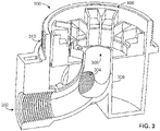
- FIG. 3 illustrate an example terminal junction box 300 that may be implemented with the example terminal blocks 100 or 200 of FIG. 1 or FIG. 2 .
- the example terminal junction box 300 of FIG. 3 is illustrated with the example terminal block 100 of FIG. 1 .
- the example terminal junction box 300 includes a first, second, and third apertures 302, 304, 306 connected via a wire guide 308 that connects to or passes through opening 122 of FIG. 1 or opening 232 of FIG. 2 . Wires pass through either the first and third apertures 302 and 306 via the example wire guide 308 or the second and third apertures 304 and 306 via the example wire guide 308 to connect with the terminal block 100 disposed within the example terminal junction box 300.
Landscapes
- Engineering & Computer Science (AREA)
- Mechanical Engineering (AREA)
- Connections Arranged To Contact A Plurality Of Conductors (AREA)
Description
- This disclosure relates generally to electrical connection apparatus and, more particularly, to terminal block.
- Process control systems are typically controlled by large numbers of field devices such as sensors, transmitters, controllers, etc. that convey information and electrical power by wires (e.g., field wiring). Oftentimes, field devices require a large amount of wiring to terminate at a single, relatively confined location. Long rows of identical termination sections are difficult to properly wire as each terminal is to receive a particular wire. Thus, field devices with numerous wire connections are more likely to be wired improperly. Document
DE-B-1057198 describes a known terminal base for three-phase motors according to the preamble of claims 1 and 6. - Independent claims 1 and 6 disclose terminal blocks according to the invention.
- Other advantageous features of said terminal blocks are specified in their corresponding dependent claims.
-
-
FIG. 1 illustrates an example terminal block in accordance with the present disclosure. -
FIG. 2 illustrates another example terminal block in accordance with the present disclosure. -
FIG. 3 illustrates an example terminal junction box that may be implemented with the example terminal blocks ofFIG. 1 orFIG. 2 . - The figures are not to scale. Instead, to clarify multiple layers and regions, the thickness of the layers may be enlarged in the drawings. Wherever possible, the same reference numbers will be used throughout the drawing(s) and accompanying written description to refer to the same or like parts. As used in this patent, stating that any part (e.g., a layer, film, area, or plate) is in any way positioned on (e.g., positioned on, located on, disposed on, or formed on, etc.) another part, means that the referenced part is either in contact with the other part, or that the referenced part is above the other part with one or more intermediate part(s) located therebetween. Stating that any part is in contact with another part means that there is no intermediate part between the two parts.
- Terminal blocks are commonly used in process control systems to connect various field devices with controllers via field wiring. In some examples, a single field device may require numerous wire connections. In such examples, a large number of wires are to be connected or terminated at a terminal block in a relatively confined space. Known terminal blocks are typically configured with identical terminals placed in a row or linear arrangement. This type of arrangement may not make the most efficient use of space and increases the likelihood of improperly wiring a field device due to the difficulty in identifying particular terminals.
- Example terminal blocks disclosed herein provide terminals arranged in an annular geometry (e.g., circular shape) and include terminals of different heights. The annular arrangement of terminals provides for more efficient use of space compared to a linear arrangement or rows of terminals. Further, disposing the terminals at different heights facilitates the identification of individual terminals, thereby facilitating quick and correct connection of field device wiring to the terminals.
- Terminal connections or terminals typically receive wire ends to mechanically retain the wires and make electrical connections. Various types of terminals include screws, clips, tongue crimps, probes, tabs, wire nuts, turrets, etc. For example, a screw terminal connection fastens an uninsulated wire end via the tightening of a screw.
- In an example terminal block disclosed herein, pairs of terminals may be arranged annularly, and the terminal pairs may have different heights to facilitate distinguishing between the pairs of terminals and/or identifying a particular terminal pair. For example, a first pair of terminals may have a first height and a second pair of terminals adjacent the first pair of terminals may have a second height, thereby making the first pair of terminals easily distinguishable from the second pair of terminals. The heights of terminal pairs can alternate through the entire terminal block such that the first pair of terminals has the first height, the second pair of terminals adjacent the first pair has the second height, a third pair of terminals adjacent the second pair has the first height, and so on. In certain examples, more than two heights may be used to distinguish the terminal pairs.
- An additional example terminal block described herein includes pairs of terminals arranged annularly such that terminals within each pair have different heights. For example, a first terminal in a first pair has a first height and a second terminal of the first pair adjacent the first terminal has a second height, thereby making the two terminals easily distinguishable from one another. Further, a second pair adjacent the first pair includes a third terminal and a fourth terminal. In some examples, the third terminal is the same height as the first terminal and the fourth terminal is the same height as the second terminal. The heights of the terminals can alternate through the entire terminal block such that the first terminal of the first pair has a first height, the second terminal of the first pair adjacent the first terminal has the second height, a third terminal of the second pair has the first height, and so on. In some examples, more than two heights may be used to distinguish the terminal pairs.
-
FIG. 1 illustrates anexample terminal block 100 having an annular arrangement of terminal connection pairs having different heights. In the illustrated example, theterminal block 100 has eight terminal pairs having two heights, while in other examples, the number of terminal pairs may be greater or fewer. - The
example terminal block 100 includes afirst terminal pair 102 having afirst body portion 104. Adjacent thefirst terminal pair 102 is asecond terminal pair 106 having asecond body portion 108. Each of thefirst terminal pair 102 and thesecond terminal pair 106 has a pair ofterminals 110. In the illustrated example, theterminals 110 are screw terminals. However, in other examples, theterminals 110 can be any type of terminal connection (e.g., clip, tongue crimp, tab, etc.). Additionally or alternatively, some of theterminals 110 may be one type while other ones of theterminals 110 may be another type. - In the illustrated example, the
first body portion 104 and thesecond body portion 108 have rectangular slots divided by a partition. In some examples, the rectangular slots have an "E" planform shape. For example, thefirst body portion 104 has twocompartments respective terminal 110 adjacent one another and disposed within inner andouter partitions inner partition 116 is angled such that it generally forms a disc sector. In various other examples, thebody portions outer partitions 118 can be angled to form similar disc sectors. In the illustrated example, the arrangement and shape of thefirst body portion 104 and thesecond body portion 108 is such that the periphery of thebody portions - In some examples, the
first terminal pair 102 and thesecond terminal pair 106 can be manufactured as one piece, can be joined together with an adhesive or joining mechanism (e.g., glue, latch, screw etc.), or can be placed adjacent one another. Further, thefirst body portion 104 and thesecond body portion 108 may be formed via an electrically insulating material, such as plastic, ceramic, or rubber. For example, a unitaryterminal block body 120 may be formed as a unitary molded plastic body. - In the illustrated example, the
first body portion 104 has a height different from thesecond body portion 108. The difference in height is sufficient to visually distinguish the firstterminal pair 102 from the second terminal pair 106 (e.g., 0.25 inch difference). In certain examples the height difference between the examplefirst body portion 104 and the examplesecond body portion 108 may be greater or lesser. Additionally, in some examples, a third body portion may have a third height different from the examplefirst body portion 104 and thesecond body portion 108. - In some examples, the
first body portion 104 and thesecond body portion 108 are formed together in the unitaryterminal block body 120. In the illustrated example, the unitaryterminal block body 120 has enough pairs to form a circle of terminal pairs. In other examples, more pairs may be accommodated by a larger circle or the terminal pairs may form a partial circle. Additionally, the unitaryterminal block body 120 includes anopening 122 disposed within the annular arrangement of terminal pairs. In some examples, theopening 122 may be central relative to the unitaryterminal block body 120. In other examples, theopening 122 may be offset relative to the center of the unitaryterminal block body 120. In use, electrical wires can be passed through theopening 122 to facilitate connections to theexample terminals 110. -
FIG. 2 illustrates anexample terminal block 200 having an annular arrangement of terminal pairs having terminals disposed at different heights. In the illustrated example, theterminal block 200 has eight terminal pairs having two heights, while in other examples, the number of terminal pairs may be greater or fewer. - The
example terminal block 200 includes a firstterminal pair 202 having afirst body portion 204. Adjacent the firstterminal pair 202 is a secondterminal pair 206 having asecond body portion 208. The firstterminal pair 202 includes a first terminal 210 and asecond terminal 212 and the secondterminal pair 206 includes athird terminal 214 and afourth terminal 216. In the illustrated example, theterminals 110 are screw terminals. However, in other examples, theterminals 110 can be any type of terminal connection (e.g., clip, tongue crimp, tab, etc.). Additionally or alternatively, some of theterminals 110 may be one type while other ones of theterminals 110 may be of another type. - In the illustrated example, the
first body portion 204 and thesecond body portion 208 have rectangular slots divided by a partition. In some examples, the rectangular slots have an "E" planform shape. For example, thefirst body portion 204 has twocompartments 220, 222, each having a terminal 110 adjacent one another and disposed within inner andouter partitions inner partition 224 is angled such that it generally forms a disc sector. In various other examples, the first body or the second body have obround or triangular slots divided by a partition. In some examples, the obround slots may have an "m" planform shape or the triangular slots may have a "w" planform shape. Additionally or alternatively, theouter partitions 226 can be angled to form similar disc sectors. In the illustrated example, the arrangement and shape of thefirst body portion 204 and thesecond body portion 208 is such that the periphery of thebody portions - In some examples, the first
terminal pair 202 and the secondterminal pair 206 can be manufactured as one piece, can be joined together with an adhesive or joining mechanism (e.g., glue, latch, screw etc.), or can be placed adjacent one another. Further, thefirst body portion 204 andsecond body portion 208 may be formed via an electrically insulating material, such as plastic, ceramic, or rubber. For example, a unitaryterminal block body 230 may be formed as a unitary molded plastic body. - In the illustrated example, the first terminal 210 has a height different from the
second terminal 212. The difference in height is sufficient to visually distinguish the first terminal 210 from the second terminal 212 (e.g., 0.25 inch difference). In certain examples the height difference between the example first terminal 210 and the examplesecond terminal 212 may be greater or lesser. In the illustrated example, thethird terminal 214 is adjacent to thesecond terminal 212 and thethird terminal 214 is a different height from thesecond terminal 212 and thefourth terminal 216. Further, the examplethird terminal 214 is the same height as the example first terminal 210, while the examplefourth terminal 216 is the same height as the examplesecond terminal 212. In other examples, the four terminals may all be of different heights or split amongst three heights, but no two adjacent terminals are of the same height. - In some examples, the
first body portion 204 and thesecond body portion 208 are formed together in the unitaryterminal block body 230. In the illustrated example, the unitaryterminal block body 230 has enough pairs to form a circle of terminal pairs. In other examples, more pairs may be accommodated by a larger circle or terminal pairs may form a partial circle. Additionally, the unitaryterminal block body 230 includes anopening 232 disposed within the annular arrangement of terminal pairs. In some examples, theopening 232 may be central relative to the unitaryterminal block body 230, while in other examples, it may be offset relative to the center of the unitaryterminal block body 230. In use, electrical wires can be passed through theopening 232 to facilitate connections to theexample terminals 110. -
FIG. 3 illustrate an exampleterminal junction box 300 that may be implemented with the example terminal blocks 100 or 200 ofFIG. 1 orFIG. 2 . The exampleterminal junction box 300 ofFIG. 3 is illustrated with theexample terminal block 100 ofFIG. 1 . - The example
terminal junction box 300 includes a first, second, andthird apertures wire guide 308 that connects to or passes through opening 122 ofFIG. 1 or opening 232 ofFIG. 2 . Wires pass through either the first andthird apertures example wire guide 308 or the second andthird apertures example wire guide 308 to connect with theterminal block 100 disposed within the exampleterminal junction box 300. - While the examples disclosed herein are described in connection with industrial field devices, the examples disclosed herein can likewise be implemented with any other type of electrical device requiring a terminal connection.
- Although certain example apparatus and articles of manufacture have been disclosed herein, the scope of coverage of this patent is not limited thereto. On the contrary, this patent covers all methods, apparatus and articles of manufacture fairly falling within the scope of the claims of this patent.
Claims (14)
- A terminal block (100) comprising:a unitary terminal block body (120); andan annular arrangement of terminal pairs (102, 106) mounted within the unitary terminal block body (120), each of the terminal pairs (102, 106) having a first height and being adjacent another terminal pair (102, 106) having a second height different from the first height,characterized in that the unitary terminal block body (120) has an opening (122) disposed within the annular arrangement of terminal pairs (102, 106) so that each of the terminal pairs (102, 106) is arranged to receive respective wires extending through the opening (122).
- The terminal block of claim 1, wherein each of the terminal pairs (102, 106) includes a pair of screw terminals to capture wire ends.
- The terminal block of any preceding claim, wherein the first heights are equal and the second heights are equal.
- The terminal block of any preceding claim, wherein the annular arrangement of terminal pairs (102, 106) forms a circle.
- The terminal block of any preceding claim, wherein the unitary terminal block body (120) is composed of molded plastic.
- The terminal block of any preceding claim, wherein the annular arrangement of terminal pairs includes a first terminal pair (102) having a first body portion (104) and a second terminal pair (106) that is adjacent the first terminal pair (102) and has a second body portion (108), and wherein the first body portion (104) and the second body portion (108) have rectangular slots divided by a partition.
- The terminal block of claim 6, wherein the first body portion (104) has two compartments (112, 114) each having a respective terminal (110) adjacent one another and disposed within inner and outer partitions (116, 118).
- A terminal block (200) comprising:a unitary terminal block body (230); andan annular arrangement of terminal pairs (202, 206) mounted within the unitary terminal block body (230), each of the terminal pairs (202, 206) having a first terminal (210) having a first height and being adj acent to a second terminal (212) having a second height different from the first height,characterized in that the unitary terminal block body (230) has an opening (232) disposed within the annular arrangement of terminal pairs (202, 206) so that each of the terminal pairs (202, 206) is arranged to receive respective wires extending through the opening (232).
- The terminal block of claim 8, wherein each of the terminal pairs (202, 206) includes a pair of screw terminals to capture wire ends.
- The terminal block of claim 8 or 9, wherein the first heights are equal and the second heights are equal.
- The terminal block of claim 8, 9 or 10, wherein the annular arrangement of terminal pairs (202, 206) forms a circle.
- The terminal block of claim 8, 9, 10 or 11, wherein the unitary terminal block body (230) is composed of molded plastic.
- The terminal block of claim 8, 9, 10, 11 or 12, wherein the annular arrangement of terminal pairs includes a first terminal pair (202) having a first body portion (204) and a second terminal pair (206) that is adjacent the first terminal pair (202) and has a second body portion (208), and wherein the first body portion (204) and the second body portion (208) have rectangular slots divided by a partition.
- The terminal block of claim 13, wherein the first body portion (204) has two compartments (220, 222) each having a respective terminal (110) adjacent one another and disposed within inner and outer partitions (224, 226).
Applications Claiming Priority (2)
| Application Number | Priority Date | Filing Date | Title |
|---|---|---|---|
| US15/599,992 US10164354B2 (en) | 2017-05-19 | 2017-05-19 | Terminal block apparatus |
| PCT/US2018/030564 WO2018212992A1 (en) | 2017-05-19 | 2018-05-02 | Terminal block apparatus |
Publications (2)
| Publication Number | Publication Date |
|---|---|
| EP3625853A1 EP3625853A1 (en) | 2020-03-25 |
| EP3625853B1 true EP3625853B1 (en) | 2022-08-10 |
Family
ID=62200565
Family Applications (1)
| Application Number | Title | Priority Date | Filing Date |
|---|---|---|---|
| EP18726002.1A Active EP3625853B1 (en) | 2017-05-19 | 2018-05-02 | Terminal block apparatus |
Country Status (6)
| Country | Link |
|---|---|
| US (1) | US10164354B2 (en) |
| EP (1) | EP3625853B1 (en) |
| CN (2) | CN108963482B (en) |
| CA (1) | CA3063587A1 (en) |
| RU (1) | RU2019139363A (en) |
| WO (1) | WO2018212992A1 (en) |
Cited By (1)
| Publication number | Priority date | Publication date | Assignee | Title |
|---|---|---|---|---|
| GB2640913A (en) * | 2024-05-09 | 2025-11-12 | Qjb Ltd | A junction box |
Families Citing this family (4)
| Publication number | Priority date | Publication date | Assignee | Title |
|---|---|---|---|---|
| US10164354B2 (en) * | 2017-05-19 | 2018-12-25 | Fisher Controls International Llc | Terminal block apparatus |
| WO2019028048A1 (en) * | 2017-07-31 | 2019-02-07 | Pentair Flow Technologies, Llc | Ring-style terminal block and submersible pump with ring-style terminal block |
| US11095055B2 (en) | 2019-12-20 | 2021-08-17 | Raytheon Company | Terminal block and terminal block assembly for medium to high voltage applications |
| JP7401580B2 (en) * | 2022-02-25 | 2023-12-19 | 株式会社安川電機 | Terminal blocks, electrical equipment |
Family Cites Families (6)
| Publication number | Priority date | Publication date | Assignee | Title |
|---|---|---|---|---|
| US2699533A (en) * | 1951-02-26 | 1955-01-11 | Devere Company | Plural-circuit connector |
| DE1057198B (en) | 1953-04-08 | 1959-05-14 | Siemens Ag | Terminal board for three-phase motors |
| US5266057A (en) * | 1990-03-29 | 1993-11-30 | Monster Cable Products, Inc. | Electronic power distribution device |
| US7279633B2 (en) * | 2005-01-31 | 2007-10-09 | Robert Waters | Apparatus for providing an electrical wiring hub |
| US7614922B1 (en) * | 2008-02-19 | 2009-11-10 | Genlyte Thomas Group Llc | Quick attachment junction box |
| US10164354B2 (en) * | 2017-05-19 | 2018-12-25 | Fisher Controls International Llc | Terminal block apparatus |
-
2017
- 2017-05-19 US US15/599,992 patent/US10164354B2/en active Active
-
2018
- 2018-05-02 EP EP18726002.1A patent/EP3625853B1/en active Active
- 2018-05-02 WO PCT/US2018/030564 patent/WO2018212992A1/en not_active Ceased
- 2018-05-02 RU RU2019139363A patent/RU2019139363A/en unknown
- 2018-05-02 CA CA3063587A patent/CA3063587A1/en active Pending
- 2018-05-17 CN CN201810494810.5A patent/CN108963482B/en active Active
- 2018-05-17 CN CN201820739475.6U patent/CN208539131U/en active Active
Cited By (1)
| Publication number | Priority date | Publication date | Assignee | Title |
|---|---|---|---|---|
| GB2640913A (en) * | 2024-05-09 | 2025-11-12 | Qjb Ltd | A junction box |
Also Published As
| Publication number | Publication date |
|---|---|
| US20180337470A1 (en) | 2018-11-22 |
| CA3063587A1 (en) | 2018-11-22 |
| US10164354B2 (en) | 2018-12-25 |
| RU2019139363A3 (en) | 2021-09-09 |
| CN108963482B (en) | 2021-08-13 |
| CN208539131U (en) | 2019-02-22 |
| EP3625853A1 (en) | 2020-03-25 |
| CN108963482A (en) | 2018-12-07 |
| WO2018212992A1 (en) | 2018-11-22 |
| RU2019139363A (en) | 2021-06-21 |
Similar Documents
| Publication | Publication Date | Title |
|---|---|---|
| US10164354B2 (en) | Terminal block apparatus | |
| US7369397B2 (en) | Capacitor device | |
| JP4596255B2 (en) | Electrical conductor connection terminal | |
| CN103155366B (en) | Contact device in the stator of the electric motor | |
| US7476995B2 (en) | Central power distributing member for a brushless motor, a brushless motor provided therewith and a method of assembling it | |
| US20170025907A1 (en) | Stator for electric rotary machine | |
| US11183899B2 (en) | Stator for an electric machine, an electric machine and method for manufacturing such an electric machine | |
| JP2016115544A (en) | Manufacturing method of battery wiring module | |
| US20160172650A1 (en) | Battery wiring module manufacturing method | |
| JP6370256B2 (en) | Power storage module | |
| US6468091B2 (en) | Electrical distribution center | |
| CN104995827A (en) | Busbar-unit manufacturing method and busbar unit | |
| SE457127B (en) | ELECTRICAL CONTACT PROVIDED FOR INSULATION-INPUT CONNECTION OF MANUFACTURING CABLES AND PROCEDURES FOR PREPARING DIFFICULT CONTACT | |
| US4196959A (en) | Carrier strip for round lead pins and method for making the same | |
| US7365460B2 (en) | Stator for an electrical machine | |
| EP0107247B1 (en) | Electrical machine | |
| JPS6412068B2 (en) | ||
| US10476196B2 (en) | Electrical connector with contacts holding spring-loaded pins | |
| EP3783776A1 (en) | Coil support for electric motor | |
| JPH0266857A (en) | Potential connecting method | |
| US5212346A (en) | Electrical junction box | |
| WO2004097856A1 (en) | Wire harness manufacturing method and wire harness | |
| CN112332034A (en) | Cell contact device and battery system | |
| JPH08222297A (en) | Installing structure of terminal metal fitting | |
| KR200458499Y1 (en) | Terminal for compressing cable |
Legal Events
| Date | Code | Title | Description |
|---|---|---|---|
| STAA | Information on the status of an ep patent application or granted ep patent |
Free format text: STATUS: UNKNOWN |
|
| STAA | Information on the status of an ep patent application or granted ep patent |
Free format text: STATUS: THE INTERNATIONAL PUBLICATION HAS BEEN MADE |
|
| PUAI | Public reference made under article 153(3) epc to a published international application that has entered the european phase |
Free format text: ORIGINAL CODE: 0009012 |
|
| STAA | Information on the status of an ep patent application or granted ep patent |
Free format text: STATUS: REQUEST FOR EXAMINATION WAS MADE |
|
| 17P | Request for examination filed |
Effective date: 20191114 |
|
| AK | Designated contracting states |
Kind code of ref document: A1 Designated state(s): AL AT BE BG CH CY CZ DE DK EE ES FI FR GB GR HR HU IE IS IT LI LT LU LV MC MK MT NL NO PL PT RO RS SE SI SK SM TR |
|
| AX | Request for extension of the european patent |
Extension state: BA ME |
|
| RIN1 | Information on inventor provided before grant (corrected) |
Inventor name: HALL, KENNETH, EUGENE Inventor name: HAGER, RONALD, CHARLES Inventor name: RAYMOND, WILLIAM SEAN Inventor name: CERKA, BENJAMIN, AUGUST |
|
| DAV | Request for validation of the european patent (deleted) | ||
| DAX | Request for extension of the european patent (deleted) | ||
| STAA | Information on the status of an ep patent application or granted ep patent |
Free format text: STATUS: EXAMINATION IS IN PROGRESS |
|
| 17Q | First examination report despatched |
Effective date: 20201102 |
|
| GRAP | Despatch of communication of intention to grant a patent |
Free format text: ORIGINAL CODE: EPIDOSNIGR1 |
|
| STAA | Information on the status of an ep patent application or granted ep patent |
Free format text: STATUS: GRANT OF PATENT IS INTENDED |
|
| INTG | Intention to grant announced |
Effective date: 20220222 |
|
| GRAS | Grant fee paid |
Free format text: ORIGINAL CODE: EPIDOSNIGR3 |
|
| GRAA | (expected) grant |
Free format text: ORIGINAL CODE: 0009210 |
|
| STAA | Information on the status of an ep patent application or granted ep patent |
Free format text: STATUS: THE PATENT HAS BEEN GRANTED |
|
| AK | Designated contracting states |
Kind code of ref document: B1 Designated state(s): AL AT BE BG CH CY CZ DE DK EE ES FI FR GB GR HR HU IE IS IT LI LT LU LV MC MK MT NL NO PL PT RO RS SE SI SK SM TR |
|
| REG | Reference to a national code |
Ref country code: AT Ref legal event code: REF Ref document number: 1511239 Country of ref document: AT Kind code of ref document: T Effective date: 20220815 Ref country code: CH Ref legal event code: EP |
|
| REG | Reference to a national code |
Ref country code: IE Ref legal event code: FG4D |
|
| REG | Reference to a national code |
Ref country code: DE Ref legal event code: R096 Ref document number: 602018039081 Country of ref document: DE |
|
| REG | Reference to a national code |
Ref country code: NL Ref legal event code: MP Effective date: 20220810 |
|
| REG | Reference to a national code |
Ref country code: LT Ref legal event code: MG9D |
|
| PG25 | Lapsed in a contracting state [announced via postgrant information from national office to epo] |
Ref country code: SE Free format text: LAPSE BECAUSE OF FAILURE TO SUBMIT A TRANSLATION OF THE DESCRIPTION OR TO PAY THE FEE WITHIN THE PRESCRIBED TIME-LIMIT Effective date: 20220810 Ref country code: RS Free format text: LAPSE BECAUSE OF FAILURE TO SUBMIT A TRANSLATION OF THE DESCRIPTION OR TO PAY THE FEE WITHIN THE PRESCRIBED TIME-LIMIT Effective date: 20220810 Ref country code: PT Free format text: LAPSE BECAUSE OF FAILURE TO SUBMIT A TRANSLATION OF THE DESCRIPTION OR TO PAY THE FEE WITHIN THE PRESCRIBED TIME-LIMIT Effective date: 20221212 Ref country code: NO Free format text: LAPSE BECAUSE OF FAILURE TO SUBMIT A TRANSLATION OF THE DESCRIPTION OR TO PAY THE FEE WITHIN THE PRESCRIBED TIME-LIMIT Effective date: 20221110 Ref country code: NL Free format text: LAPSE BECAUSE OF FAILURE TO SUBMIT A TRANSLATION OF THE DESCRIPTION OR TO PAY THE FEE WITHIN THE PRESCRIBED TIME-LIMIT Effective date: 20220810 Ref country code: LV Free format text: LAPSE BECAUSE OF FAILURE TO SUBMIT A TRANSLATION OF THE DESCRIPTION OR TO PAY THE FEE WITHIN THE PRESCRIBED TIME-LIMIT Effective date: 20220810 Ref country code: LT Free format text: LAPSE BECAUSE OF FAILURE TO SUBMIT A TRANSLATION OF THE DESCRIPTION OR TO PAY THE FEE WITHIN THE PRESCRIBED TIME-LIMIT Effective date: 20220810 Ref country code: FI Free format text: LAPSE BECAUSE OF FAILURE TO SUBMIT A TRANSLATION OF THE DESCRIPTION OR TO PAY THE FEE WITHIN THE PRESCRIBED TIME-LIMIT Effective date: 20220810 |
|
| REG | Reference to a national code |
Ref country code: AT Ref legal event code: MK05 Ref document number: 1511239 Country of ref document: AT Kind code of ref document: T Effective date: 20220810 |
|
| PG25 | Lapsed in a contracting state [announced via postgrant information from national office to epo] |
Ref country code: PL Free format text: LAPSE BECAUSE OF FAILURE TO SUBMIT A TRANSLATION OF THE DESCRIPTION OR TO PAY THE FEE WITHIN THE PRESCRIBED TIME-LIMIT Effective date: 20220810 Ref country code: IS Free format text: LAPSE BECAUSE OF FAILURE TO SUBMIT A TRANSLATION OF THE DESCRIPTION OR TO PAY THE FEE WITHIN THE PRESCRIBED TIME-LIMIT Effective date: 20221210 Ref country code: HR Free format text: LAPSE BECAUSE OF FAILURE TO SUBMIT A TRANSLATION OF THE DESCRIPTION OR TO PAY THE FEE WITHIN THE PRESCRIBED TIME-LIMIT Effective date: 20220810 Ref country code: GR Free format text: LAPSE BECAUSE OF FAILURE TO SUBMIT A TRANSLATION OF THE DESCRIPTION OR TO PAY THE FEE WITHIN THE PRESCRIBED TIME-LIMIT Effective date: 20221111 |
|
| PG25 | Lapsed in a contracting state [announced via postgrant information from national office to epo] |
Ref country code: SM Free format text: LAPSE BECAUSE OF FAILURE TO SUBMIT A TRANSLATION OF THE DESCRIPTION OR TO PAY THE FEE WITHIN THE PRESCRIBED TIME-LIMIT Effective date: 20220810 Ref country code: RO Free format text: LAPSE BECAUSE OF FAILURE TO SUBMIT A TRANSLATION OF THE DESCRIPTION OR TO PAY THE FEE WITHIN THE PRESCRIBED TIME-LIMIT Effective date: 20220810 Ref country code: ES Free format text: LAPSE BECAUSE OF FAILURE TO SUBMIT A TRANSLATION OF THE DESCRIPTION OR TO PAY THE FEE WITHIN THE PRESCRIBED TIME-LIMIT Effective date: 20220810 Ref country code: DK Free format text: LAPSE BECAUSE OF FAILURE TO SUBMIT A TRANSLATION OF THE DESCRIPTION OR TO PAY THE FEE WITHIN THE PRESCRIBED TIME-LIMIT Effective date: 20220810 Ref country code: CZ Free format text: LAPSE BECAUSE OF FAILURE TO SUBMIT A TRANSLATION OF THE DESCRIPTION OR TO PAY THE FEE WITHIN THE PRESCRIBED TIME-LIMIT Effective date: 20220810 Ref country code: AT Free format text: LAPSE BECAUSE OF FAILURE TO SUBMIT A TRANSLATION OF THE DESCRIPTION OR TO PAY THE FEE WITHIN THE PRESCRIBED TIME-LIMIT Effective date: 20220810 |
|
| REG | Reference to a national code |
Ref country code: DE Ref legal event code: R097 Ref document number: 602018039081 Country of ref document: DE |
|
| PG25 | Lapsed in a contracting state [announced via postgrant information from national office to epo] |
Ref country code: SK Free format text: LAPSE BECAUSE OF FAILURE TO SUBMIT A TRANSLATION OF THE DESCRIPTION OR TO PAY THE FEE WITHIN THE PRESCRIBED TIME-LIMIT Effective date: 20220810 Ref country code: EE Free format text: LAPSE BECAUSE OF FAILURE TO SUBMIT A TRANSLATION OF THE DESCRIPTION OR TO PAY THE FEE WITHIN THE PRESCRIBED TIME-LIMIT Effective date: 20220810 |
|
| PLBE | No opposition filed within time limit |
Free format text: ORIGINAL CODE: 0009261 |
|
| STAA | Information on the status of an ep patent application or granted ep patent |
Free format text: STATUS: NO OPPOSITION FILED WITHIN TIME LIMIT |
|
| PG25 | Lapsed in a contracting state [announced via postgrant information from national office to epo] |
Ref country code: AL Free format text: LAPSE BECAUSE OF FAILURE TO SUBMIT A TRANSLATION OF THE DESCRIPTION OR TO PAY THE FEE WITHIN THE PRESCRIBED TIME-LIMIT Effective date: 20220810 |
|
| P01 | Opt-out of the competence of the unified patent court (upc) registered |
Effective date: 20230526 |
|
| 26N | No opposition filed |
Effective date: 20230511 |
|
| PG25 | Lapsed in a contracting state [announced via postgrant information from national office to epo] |
Ref country code: SI Free format text: LAPSE BECAUSE OF FAILURE TO SUBMIT A TRANSLATION OF THE DESCRIPTION OR TO PAY THE FEE WITHIN THE PRESCRIBED TIME-LIMIT Effective date: 20220810 |
|
| REG | Reference to a national code |
Ref country code: DE Ref legal event code: R119 Ref document number: 602018039081 Country of ref document: DE |
|
| REG | Reference to a national code |
Ref country code: CH Ref legal event code: PL |
|
| PG25 | Lapsed in a contracting state [announced via postgrant information from national office to epo] |
Ref country code: MC Free format text: LAPSE BECAUSE OF FAILURE TO SUBMIT A TRANSLATION OF THE DESCRIPTION OR TO PAY THE FEE WITHIN THE PRESCRIBED TIME-LIMIT Effective date: 20220810 |
|
| REG | Reference to a national code |
Ref country code: BE Ref legal event code: MM Effective date: 20230531 |
|
| PG25 | Lapsed in a contracting state [announced via postgrant information from national office to epo] |
Ref country code: MC Free format text: LAPSE BECAUSE OF FAILURE TO SUBMIT A TRANSLATION OF THE DESCRIPTION OR TO PAY THE FEE WITHIN THE PRESCRIBED TIME-LIMIT Effective date: 20220810 Ref country code: LU Free format text: LAPSE BECAUSE OF NON-PAYMENT OF DUE FEES Effective date: 20230502 Ref country code: LI Free format text: LAPSE BECAUSE OF NON-PAYMENT OF DUE FEES Effective date: 20230531 Ref country code: CH Free format text: LAPSE BECAUSE OF NON-PAYMENT OF DUE FEES Effective date: 20230531 |
|
| REG | Reference to a national code |
Ref country code: IE Ref legal event code: MM4A |
|
| PG25 | Lapsed in a contracting state [announced via postgrant information from national office to epo] |
Ref country code: IE Free format text: LAPSE BECAUSE OF NON-PAYMENT OF DUE FEES Effective date: 20230502 |
|
| PG25 | Lapsed in a contracting state [announced via postgrant information from national office to epo] |
Ref country code: DE Free format text: LAPSE BECAUSE OF NON-PAYMENT OF DUE FEES Effective date: 20231201 Ref country code: IE Free format text: LAPSE BECAUSE OF NON-PAYMENT OF DUE FEES Effective date: 20230502 |
|
| PG25 | Lapsed in a contracting state [announced via postgrant information from national office to epo] |
Ref country code: IT Free format text: LAPSE BECAUSE OF FAILURE TO SUBMIT A TRANSLATION OF THE DESCRIPTION OR TO PAY THE FEE WITHIN THE PRESCRIBED TIME-LIMIT Effective date: 20220810 Ref country code: BE Free format text: LAPSE BECAUSE OF NON-PAYMENT OF DUE FEES Effective date: 20230531 |
|
| PG25 | Lapsed in a contracting state [announced via postgrant information from national office to epo] |
Ref country code: BG Free format text: LAPSE BECAUSE OF FAILURE TO SUBMIT A TRANSLATION OF THE DESCRIPTION OR TO PAY THE FEE WITHIN THE PRESCRIBED TIME-LIMIT Effective date: 20220810 |
|
| PG25 | Lapsed in a contracting state [announced via postgrant information from national office to epo] |
Ref country code: BG Free format text: LAPSE BECAUSE OF FAILURE TO SUBMIT A TRANSLATION OF THE DESCRIPTION OR TO PAY THE FEE WITHIN THE PRESCRIBED TIME-LIMIT Effective date: 20220810 |
|
| PGFP | Annual fee paid to national office [announced via postgrant information from national office to epo] |
Ref country code: GB Payment date: 20250423 Year of fee payment: 8 |
|
| PGFP | Annual fee paid to national office [announced via postgrant information from national office to epo] |
Ref country code: FR Payment date: 20250424 Year of fee payment: 8 |
|
| PG25 | Lapsed in a contracting state [announced via postgrant information from national office to epo] |
Ref country code: CY Free format text: LAPSE BECAUSE OF FAILURE TO SUBMIT A TRANSLATION OF THE DESCRIPTION OR TO PAY THE FEE WITHIN THE PRESCRIBED TIME-LIMIT; INVALID AB INITIO Effective date: 20180502 |
|
| PG25 | Lapsed in a contracting state [announced via postgrant information from national office to epo] |
Ref country code: HU Free format text: LAPSE BECAUSE OF FAILURE TO SUBMIT A TRANSLATION OF THE DESCRIPTION OR TO PAY THE FEE WITHIN THE PRESCRIBED TIME-LIMIT; INVALID AB INITIO Effective date: 20180502 |
|
| PG25 | Lapsed in a contracting state [announced via postgrant information from national office to epo] |
Ref country code: TR Free format text: LAPSE BECAUSE OF FAILURE TO SUBMIT A TRANSLATION OF THE DESCRIPTION OR TO PAY THE FEE WITHIN THE PRESCRIBED TIME-LIMIT Effective date: 20220810 |