EP3625184B1 - Nanocarbon particle admixtures and method for making them - Google Patents
Nanocarbon particle admixtures and method for making them Download PDFInfo
- Publication number
- EP3625184B1 EP3625184B1 EP18801609.1A EP18801609A EP3625184B1 EP 3625184 B1 EP3625184 B1 EP 3625184B1 EP 18801609 A EP18801609 A EP 18801609A EP 3625184 B1 EP3625184 B1 EP 3625184B1
- Authority
- EP
- European Patent Office
- Prior art keywords
- particles
- nanocarbon
- admixture
- carbon
- mixture
- Prior art date
- Legal status (The legal status is an assumption and is not a legal conclusion. Google has not performed a legal analysis and makes no representation as to the accuracy of the status listed.)
- Active
Links
Images



Classifications
-
- C—CHEMISTRY; METALLURGY
- C04—CEMENTS; CONCRETE; ARTIFICIAL STONE; CERAMICS; REFRACTORIES
- C04B—LIME, MAGNESIA; SLAG; CEMENTS; COMPOSITIONS THEREOF, e.g. MORTARS, CONCRETE OR LIKE BUILDING MATERIALS; ARTIFICIAL STONE; CERAMICS; REFRACTORIES; TREATMENT OF NATURAL STONE
- C04B40/00—Processes, in general, for influencing or modifying the properties of mortars, concrete or artificial stone compositions, e.g. their setting or hardening ability
- C04B40/0028—Aspects relating to the mixing step of the mortar preparation
- C04B40/0039—Premixtures of ingredients
- C04B40/0046—Premixtures of ingredients characterised by their processing, e.g. sequence of mixing the ingredients when preparing the premixtures
-
- C—CHEMISTRY; METALLURGY
- C04—CEMENTS; CONCRETE; ARTIFICIAL STONE; CERAMICS; REFRACTORIES
- C04B—LIME, MAGNESIA; SLAG; CEMENTS; COMPOSITIONS THEREOF, e.g. MORTARS, CONCRETE OR LIKE BUILDING MATERIALS; ARTIFICIAL STONE; CERAMICS; REFRACTORIES; TREATMENT OF NATURAL STONE
- C04B14/00—Use of inorganic materials as fillers, e.g. pigments, for mortars, concrete or artificial stone; Treatment of inorganic materials specially adapted to enhance their filling properties in mortars, concrete or artificial stone
- C04B14/02—Granular materials, e.g. microballoons
- C04B14/022—Carbon
-
- C—CHEMISTRY; METALLURGY
- C04—CEMENTS; CONCRETE; ARTIFICIAL STONE; CERAMICS; REFRACTORIES
- C04B—LIME, MAGNESIA; SLAG; CEMENTS; COMPOSITIONS THEREOF, e.g. MORTARS, CONCRETE OR LIKE BUILDING MATERIALS; ARTIFICIAL STONE; CERAMICS; REFRACTORIES; TREATMENT OF NATURAL STONE
- C04B14/00—Use of inorganic materials as fillers, e.g. pigments, for mortars, concrete or artificial stone; Treatment of inorganic materials specially adapted to enhance their filling properties in mortars, concrete or artificial stone
- C04B14/02—Granular materials, e.g. microballoons
- C04B14/022—Carbon
- C04B14/024—Graphite
-
- C—CHEMISTRY; METALLURGY
- C04—CEMENTS; CONCRETE; ARTIFICIAL STONE; CERAMICS; REFRACTORIES
- C04B—LIME, MAGNESIA; SLAG; CEMENTS; COMPOSITIONS THEREOF, e.g. MORTARS, CONCRETE OR LIKE BUILDING MATERIALS; ARTIFICIAL STONE; CERAMICS; REFRACTORIES; TREATMENT OF NATURAL STONE
- C04B14/00—Use of inorganic materials as fillers, e.g. pigments, for mortars, concrete or artificial stone; Treatment of inorganic materials specially adapted to enhance their filling properties in mortars, concrete or artificial stone
- C04B14/02—Granular materials, e.g. microballoons
- C04B14/022—Carbon
- C04B14/026—Carbon of particular shape, e.g. nanotubes
-
- C—CHEMISTRY; METALLURGY
- C04—CEMENTS; CONCRETE; ARTIFICIAL STONE; CERAMICS; REFRACTORIES
- C04B—LIME, MAGNESIA; SLAG; CEMENTS; COMPOSITIONS THEREOF, e.g. MORTARS, CONCRETE OR LIKE BUILDING MATERIALS; ARTIFICIAL STONE; CERAMICS; REFRACTORIES; TREATMENT OF NATURAL STONE
- C04B14/00—Use of inorganic materials as fillers, e.g. pigments, for mortars, concrete or artificial stone; Treatment of inorganic materials specially adapted to enhance their filling properties in mortars, concrete or artificial stone
- C04B14/38—Fibrous materials; Whiskers
- C04B14/386—Carbon
-
- C—CHEMISTRY; METALLURGY
- C04—CEMENTS; CONCRETE; ARTIFICIAL STONE; CERAMICS; REFRACTORIES
- C04B—LIME, MAGNESIA; SLAG; CEMENTS; COMPOSITIONS THEREOF, e.g. MORTARS, CONCRETE OR LIKE BUILDING MATERIALS; ARTIFICIAL STONE; CERAMICS; REFRACTORIES; TREATMENT OF NATURAL STONE
- C04B28/00—Compositions of mortars, concrete or artificial stone, containing inorganic binders or the reaction product of an inorganic and an organic binder, e.g. polycarboxylate cements
- C04B28/02—Compositions of mortars, concrete or artificial stone, containing inorganic binders or the reaction product of an inorganic and an organic binder, e.g. polycarboxylate cements containing hydraulic cements other than calcium sulfates
-
- C—CHEMISTRY; METALLURGY
- C04—CEMENTS; CONCRETE; ARTIFICIAL STONE; CERAMICS; REFRACTORIES
- C04B—LIME, MAGNESIA; SLAG; CEMENTS; COMPOSITIONS THEREOF, e.g. MORTARS, CONCRETE OR LIKE BUILDING MATERIALS; ARTIFICIAL STONE; CERAMICS; REFRACTORIES; TREATMENT OF NATURAL STONE
- C04B2103/00—Function or property of ingredients for mortars, concrete or artificial stone
- C04B2103/10—Accelerators; Activators
-
- C—CHEMISTRY; METALLURGY
- C04—CEMENTS; CONCRETE; ARTIFICIAL STONE; CERAMICS; REFRACTORIES
- C04B—LIME, MAGNESIA; SLAG; CEMENTS; COMPOSITIONS THEREOF, e.g. MORTARS, CONCRETE OR LIKE BUILDING MATERIALS; ARTIFICIAL STONE; CERAMICS; REFRACTORIES; TREATMENT OF NATURAL STONE
- C04B2103/00—Function or property of ingredients for mortars, concrete or artificial stone
- C04B2103/20—Retarders
-
- C—CHEMISTRY; METALLURGY
- C04—CEMENTS; CONCRETE; ARTIFICIAL STONE; CERAMICS; REFRACTORIES
- C04B—LIME, MAGNESIA; SLAG; CEMENTS; COMPOSITIONS THEREOF, e.g. MORTARS, CONCRETE OR LIKE BUILDING MATERIALS; ARTIFICIAL STONE; CERAMICS; REFRACTORIES; TREATMENT OF NATURAL STONE
- C04B2103/00—Function or property of ingredients for mortars, concrete or artificial stone
- C04B2103/30—Water reducers, plasticisers, air-entrainers, flow improvers
- C04B2103/302—Water reducers
-
- C—CHEMISTRY; METALLURGY
- C04—CEMENTS; CONCRETE; ARTIFICIAL STONE; CERAMICS; REFRACTORIES
- C04B—LIME, MAGNESIA; SLAG; CEMENTS; COMPOSITIONS THEREOF, e.g. MORTARS, CONCRETE OR LIKE BUILDING MATERIALS; ARTIFICIAL STONE; CERAMICS; REFRACTORIES; TREATMENT OF NATURAL STONE
- C04B2103/00—Function or property of ingredients for mortars, concrete or artificial stone
- C04B2103/40—Surface-active agents, dispersants
Definitions
- This disclosure relates to nanocarbon particle admixtures and a method for making them.
- Carbon nanotubes are being used to enhance properties, including strength, in a variety of materials.
- Portland cement can include dispersed carbon nanotubes (CNTs) for making high-performance concrete and other cement-based materials.
- Calcium silicate hydrate (CSH) is the main product of the hydration of Portland cement and is primarily responsible for the strength in concrete.
- CSH Calcium silicate hydrate
- the ultra-strong carbon nanotubes (CNTs) form nanostructures that function as nanoscopic reinforcement to strengthen the concrete.
- CNTs and other nanometer scale carbon particles can provide a very high number of finely-dispersed nucleation sites for CSH formation, which densifies the cured cement matrix in concrete composite materials, further strengthening the material and improving other desirable characteristics, such as lower permeation, higher abrasion resistance, and better bonding between the cement and other aggregate materials in the concrete mix.
- the carbon nanotubes (CNTs) or other nanocarbon particles can originally be included in an admixture, which is added to the cement.
- admixtures are the ingredients for the concrete other than the typical cement (and supplementary cementing materials), water, and aggregate (sand and stones).
- Admixtures are usually liquid additives that are added before or during concrete mixing.
- CNTs carbon nanotubes
- concrete is a bulk material that has to be produced with a low cost. It would be commercially advantageous to have the capability to manufacture admixtures for concrete that contain carbon nanotubes (CNTs), as well as other nanocarbon materials, in a cost effective and efficient manner.
- the present disclosure is directed to nanocarbon particle admixtures and a method for making them.
- a method for making an admixture in liquid form for concrete includes the providing a nanocarbon mixture as a carbon powder that includes at least two different types of nanocarbon particles, selected from the group consisting of carbon nanotube particles, carbon nanofiber particles, graphene particles, graphite particles, carbon black, "amorphous" paracrystalline, polycrystalline carbon particles, nanodiamonds, single-layer fullerene particles and multi-layer fullerene particles; wetting and mixing the carbon powder into a water/surfactant mixture comprised of water and a surfactant configured to de-agglomerate and uniformly disperse the nanocarbon particles in the water/surfactant mixture containing the carbon powder configured for addition to a concrete material comprising a cementitious material, blending the nanocarbon mixture with a nano-silica based compound, wherein quantities of the nanocarbon mixture, superplasticizer surfactant, nano-silica based compound and water in the admixture are:
- the nanocarbon mixture can be produced using a heated reactor and catalytic decomposition of a hydrocarbon feed gas.
- a catalyst and reaction conditions in the reactor are selected to provide different types of nanocarbon particles in selected mass percentage ranges.
- the reaction conditions and the catalyst can be selected and controlled such that the nanocarbon mixture includes at least two different types of nanocarbon particles as described above.
- the nanocarbon mixture can be provided as a desired composition of nanocarbon particles.
- certain nanocarbon materials are mass produced and commercially available in industrial commodity markets from a producer. With either production or commercial purchase of the nanocarbon mixture, different types of nanocarbon particles produced from different processes can be blended or mixed together to provide a particular nanocarbon mixture having desired characteristics, such as desired mass percentage ranges of the different nanocarbon particles.
- the desired ratio of the nanocarbon particles to the cementitious material is from 0.0002% by mass to 0.0199% by mass.
- the step providing the nanocarbon mixture can also include the step of crushing or grinding the nanocarbon mixture into a powder configured for uniform dispersion in water. This process can be performed using a suitable mechanical crushing or grinding apparatus.
- the method can include the steps of storing, conveying, and transporting the nanocarbon mixture in the carbon powder form.
- the nanocarbon mixture can be stored in a relatively large vessel, such as a silo or tank, having an inlet/outlet in flow communication with a conveyor configured to transport the nanocarbon mixture to a desired location.
- the method also includes the steps of wetting and mixing predetermined quantity of the nanocarbon mixture in carbon powder form in a predetermined quantity of water/surfactant mixture with intense, high energy, large scale mixing equipment. During the wetting and mixing step, the nanocarbon particles, and other nano-particles as well, are de-agglomerated and uniformly dispersed in the liquid admixture.
- the water/surfactant mixture can include a predetermined quantity of a superplasticizer surfactant.
- the method can also include the step of blending the nanocarbon mixture with a nano-silica based compound for long-term stability of the suspended nanocarbon particles in the liquid admixture, either before or after the wetting and mixing step. If performed before the wetting and mixing step, this step can be used to uniformly disperse and de-agglomerate the nano-silica based particles into the nanocarbon mixture.
- the method can also include the step of blending the nanocarbon mixture with an organic compound including a functional group that contains a basic nitrogen atom with a lone pair to increase early and/or late strength development in the concrete. Dosage is typically in the range of 0.5 to 20% by mass of the admixture. A low dosage will typically improve early strength and a high dose will typically improve late strength of the concrete.
- the method can also include the step of storing the liquid admixture for specific quality control testing.
- the storing step can also include the step of longer-term warehousing and storage with controlled environmental conditions and equipment for scheduled recirculation of the admixture and quality control checks.
- the method can also include the step of packaging the liquid admixture in a container for single-use or bulk sales and distribution.
- the nanocarbon particles can include 43% to 58% by mass of carbon nanotube particles.
- the nanocarbon particles can include 30% to 50% by mass of carbon nanofiber particles.
- An admixture in liquid form for making concrete includes a suspension of uniformly dispersed nanocarbon particles in a water/surfactant mixture.
- the nanocarbon particles include at least two different types of particles selected from the group consisting of carbon nanotube particles, carbon nanofiber particles, graphene particles, graphite particles, carbon black and "amorphous" paracrystalline or polycrystalline carbon particles, nanodiamonds, and single-layer or multi-layer fullerene particles, with the carbon nanoparticles having a predetermined percentage range of from 0.4% to 1.9% of a total mass of the admixture;
- the admixture in liquid form for making concrete can further include an organic compound including a functional group that contains a basic nitrogen atom with a lone pair, having a percentage range from 0.5 to 20% by mass of the admixture.
- the nanocarbon particles can comprise 43% to 58% of carbon nanotube particles based on a total mass of the nanocarbon particles.
- the nanocarbon particles can comprise 30% to 50% of carbon nanofiber particles based on a total mass of the nanocarbon particles.
- a nanocarbon/total cementitious material ratio in the concrete is from 0.0002% to 0.034% by mass.
- a nanocarbon/total cementitious material ratio in the concrete is from 0.001% to 0.1% by mass.
- cement means a material in either a cured or an uncured state that includes cement (with or without supplementary cementing materials, such as blast furnace slag, fly ash, limestone fines, and silica fume), mineral aggregate sand and stones, and water.
- cement means hydratable cement such as Portland cement produced from clinker containing hydraulic calcium silicates.
- supplementary cementing or “cementitious” means materials that form a plastic paste when mixed with a liquid, which harden and function as a glue or binder for holding the composite concrete material together. Cementitious materials form a hard matrix to bind aggregates and contribute to the properties of hardened concrete through hydraulic or pozzolanic activity.
- Portland cement is a common concrete matrix material
- alternative examples include, but not limited to, various limes and mortars, fly ashes, ground blast-furnace slag, and silica fume.
- admixture means ingredients added to concrete before or during mixing.
- superplasticizer means a surfactant used to uniformly disperse particles in uncured concrete.
- nanocarbon particle means a particle comprising an allotrope of carbon with one or more particle dimensions on the order of 500 nanometers (nm) or less.
- Nanotubes mean cylindrical nanostructures comprising one or more cylindrical tubes of atoms having a high length to diameter ratio. Nanotubes can be categorized as single-walled nanotubes (SWNTs) or multi-walled nanotubes (MWNTs).
- SWNTs single-walled nanotubes
- MWNTs multi-walled nanotubes
- Nanotube particles comprise individual molecules, particles, or agglomerates of particles comprised of nanotubes.
- Nanofibers means cylindrical nanostructures with a high length to diameter ratio, with atomic layers in a stacked plate, cup, or cone configuration.
- Nanofiber particles comprise individual molecules, particles, or agglomerates of particles comprised of nanofibers.
- Graphene means small particles of a two-dimensional hexagonal lattice of carbon atoms. Graphene is the basic structure of many other allotropes of carbon, including carbon nanotubes, carbon nanofibers, graphite, and other fullerenes.
- Graphite means a carbon crystalline atomic structure comprised of layers of graphene.
- Carbon black means a fine powder comprised of nanometer scale particles and agglomerates with an "amorphous" paracrystalline or polycrystalline atomic structure, usually made from decomposition and incomplete combustion of hydrocarbon feedstocks, but for the purposes of this disclosure, “carbon black” also includes finely-ground charcoal, coal, or activated carbon materials.
- Nanomonds means nanometer scale particles of a carbon allotrope with diamond crystal atomic structure.
- Fralerene means molecules or particles comprised of graphitic crystalline structures with defects in the hexagonal atomic lattice that bend or curve the layer(s) into spheres ("onions"), buds, cones, horns, tubes, or other composite shapes built from sub-structures with these simpler forms.
- Nano-silica means silica material with one or more particle dimensions on the order of 500 nanometers (nm) or less.
- a nanocarbon mixture containing a selected percentage range of CNTs is shown in raw, bulk form following production using a heated reactor and catalytic decomposition of a hydrocarbon feed gas.
- the nanocarbon mixture comprises CNTs containing defects as well as other amorphous forms of nanocarbon as well as catalyst particles.
- the CNTs comprise multi walled CNTs (MWCNTs) but can also include single walled CNTs (SWCNTs).
- the CNTs can occur in bundles of CNTs entrained in amorphous carbon structures.
- the nanocarbon mixture has the texture of powder but includes large clumps and agglomerates of carbon material such as bundles containing CNTs and amorphous carbon.
- the nanocarbon mixture is shown following grinding into a carbon powder.
- the carbon powder facilitates dispersion of the nanocarbon mixture in a water/surfactant mixture.
- a CNT/amorphous carbon bundle and a few, long individual tubes in the nanocarbon mixture are shown, with diameters ⁇ 100nm and tube lengths varying from ⁇ 200nm to >20,000nm.
- a CNT/nanocarbon bundle in the nanocarbon mixture is shown with the finely ground bundles typically ranging from 5 ⁇ m to 1500 ⁇ m.
- CNTs in the nanocarbon mixture are shown having hollow cores and many defects, such as bends, twists, and bamboo sections.
- a nanocarbon particle in the nanocarbon mixture is shown with some graphitic internal structure, but not specifically a hollow CNT or strictly amorphous.
- FIG 15 a broad Raman spectrum is shown for a typical nanocarbon mixture produced using a heated reactor and catalytic decomposition of a hydrocarbon feed gas.
- Figure 16 is a close up view of the D and G mode peaks of the Raman spectrum.
- Raman spectroscopy was used to characterize the nanocarbon particles in the nanocarbon mixture.
- Raman spectroscopy was used to verify that the nanocarbon mixture contains multiwall nanotubes, primarily comprised of carbon arranged in a graphitic crystal structure, along with other "amorphous" carbon.
- the second major peak at ⁇ 1590 1/cm shows that a slight majority of the carbon structure is graphitic (CNTs).
- the first major peak at ⁇ 1360 1/cm indicates that tube defects and amorphous carbon forms are also present in the nanocarbon mixture.
- the area of the D peak relative to the G peak shows that defects and amorphous carbon atomic structures are quite common in this carbon multiwall nanotube sample, as verified by the TEM images above.
- a small “peak” from ⁇ 200 1/cm to ⁇ 500 1/cm is indicative of the wide range of tube diameters in the sample.
- the third major peak at ⁇ 2720 1/cm (G' mode) is the second harmonic of the D mode peak, which is not very useful for characterization of this product, so it is omitted for the close-up of the D and G peaks shown in Fig. 16 .
- the Raman spectrum shown in Figures 15 and 16 indicates that the nanocarbon mixture contains about 50-60% CNTs.
- the remainder of the nanocarbon particles, which are less than about 50% of the total number of nanocarbon particles, are not in pure graphitic form.
- the nanocarbon particles can comprise from 43% to 58% by mass of CNTs.
- the nanocarbon particles comprise from 30% to 50% by mass of CNTs.
- CNFs carbon nanofibers
- the CNF nanocarbon mixture was produced using a heated reactor and catalytic decomposition of a hydrocarbon feed gas and contains a selected percentage range of CNFs.
- the nanocarbon mixture comprises CNFs containing defects as well as other amorphous forms of nanocarbon.
- the CNF nanocarbon mixture has the texture of powder but includes large clumps and agglomerates of carbon material. As with the nanocarbon mixture shown in Figure 2 , the CNF nanocarbon mixture can also be crushed or ground into a powder (not shown). While also generally cylindrical in shape, CNFs differ from CNTs because their structure is comprised of stacked disks, cones or cups of generally graphitic sheets of carbon atoms. CNFs typically have a larger average diameter and shorter average length than CNTs, as well.
- FIG 18 a bundle of CNFs in the CNF nanocarbon mixture is shown. As shown in Figure 19 , the CNFs do not have a hollow interior structure. As shown in Figure 20 , the CNFs have a "stacked cups" internal structure. In Figure 21 , CNF/amorphous nanocarbon clumps are shown in the nanocarbon mixture. Figure 22 shows the CNF/nanocarbon fibers with non-uniform diameters and lengths.
- Raman spectroscopy can be used to verify that the CNF nanocarbon mixture contains carbon nanofibers (CNFs), which are primarily comprised of the stacked plates, cones, or cups of carbon arranged in layers of a graphite (hexagonal) crystal structure, along with other "amorphous" carbon.
- CNFs carbon nanofibers
- Figure 23 is a typical Raman spectrum for the CNF nanocarbon mixture.
- the second major peak at the ⁇ 1590 1/cm (“G mode) shows that much of the carbon structure is graphitic (CNFs).
- the first major peak at ⁇ 1360 1/cm (“D mode”) indicates that defects in the stacked layers of the fibers and amorphous carbon forms are the majority of the CNF/nanocarbon product composition.
- the Raman spectrum shown in Figure 23 indicates that the CNF nanocarbon mixture contains about 30-50% CNFs and more than about 50% is not in pure graphitic form.
- the nanocarbon particles can comprise from 43% to 58% by mass of CNFs.
- the nanocarbon particles comprise from 30% to 50% by mass of CNFs.
- the system 10 is configured to perform a batch process, but can alternately be configured to continuously produce the CNF nanocarbon mixture.
- the system 10 includes a hydrocarbon feed gas supply 12 configured to supply a hydrocarbon feed gas 14.
- the hydrocarbon feed gas 14 can comprise pure methane or natural gas obtained from a "fossil fuel" deposit. Natural gas is typically about 90% methane, along with small amounts of ethane, propane, higher hydrocarbons, and "inerts" like carbon dioxide or nitrogen. Alternately, the hydrocarbon feed gas 14 can comprise a higher order hydrocarbon such as ethylene or propane.
- the hydrocarbon feed gas supply 12 can comprise a tank (or a pipeline) configured to supply the hydrocarbon feed gas 14 at a selected temperature, pressure, and flow rate.
- the temperature of the hydrocarbon feed gas 14 can be from 600 to 900°C
- the pressure can be from 0.0123 to 0.0615 atmospheres
- the flow rate can be from 0.05 to 3.0 liter/minute per gram of catalyst.
- the system 10 also includes a reactor 16 comprising a hollow reactor cylinder having a sealable inlet 22, a reaction chamber 20 in fluid communication with the inlet 22, and a sealable outlet 24 in fluid communication with the reaction chamber 20 adapted to discharge the nanocarbon mixture 38, which can comprise a nanocarbon mixture having the composition shown in Figure 15 , or a CNF nanocarbon mixture having the composition shown in Figure 23 , depending on the process parameters.
- the method produces a product gas 34 comprised of hydrogen and unreacted hydrocarbon feed gas.
- the reaction chamber 20 can be heated by thermal combustion or electricity to a temperature of from 600 to 900°C.
- the reaction chamber 20 can be in fluid communication with an inert gas supply 28.
- the system 10 can also includes a catalyst transport system 18 adapted to move a metal catalyst 30 through the reaction chamber 20 in contact with the hydrocarbon feed gas 14 to produce the nanocarbon mixture 38 and the product gas 28.
- the catalyst transport system 18 can be in the form of a chain conveyor system, a rotating auger system, a high velocity pneumatic system or a plunger system.
- the catalyst transport system 18 is adapted to move a selected amount of the metal catalyst 30 through the reaction chamber 20 at a rate dependent on the flow rate of the hydrocarbon feed gas 14. For example, with the flow rate of the hydrocarbon feed gas 14 between 0.05 and 3.0 liters/minute, the selected amount of the metal catalyst 30 can be about one gram/minute.
- the metal catalyst 30 can be simply placed in the reaction chamber 20.
- the metal catalyst 30 can be provided in the form of particles.
- a preferred metal for the metal catalyst 30 comprises Ni, or an alloy containing Ni.
- the metal can comprise NiAl, or Ni alloyed with Cu, Pd, Fe, Co, or an oxide such as MgO, ZnO, Mo 2 O 3 or SiO 2 .
- the metal catalyst 30 can comprise another metal, such as a metal selected from group VIII of the periodic table including Fe, Co, Ru, Pd and Pt.
- the system 10 also includes a carbon separator 40 adapted to separate the nanocarbon mixture 38 from the product gas 34 via gravity or cyclonic separation.
- the system 10 can also include a high energy mixer (not shown) configured to mix the nanocarbon mixture 38 with water and a superplasticizer surfactant to form the liquid admixture.
- the high energy mixer can also be used to mix a nano-silica based compound for long-term stability of the suspended nanocarbon particles in the liquid admixture.
- Suitable high energy mixers can include one or more of the following: high-shear rotating mixers, such as pumps and turbines, rotor/stator mixers, and blade dispersers; mechanical grinding and impact-type mixers, such as attritors, ball mills, and hammer mills; and high pressure fluidic mixing devices, such as nozzles, orifices, and high-velocity impact devices, such as homogenizer pumps, valves and similar equipment.
- high-shear rotating mixers such as pumps and turbines, rotor/stator mixers, and blade dispersers
- mechanical grinding and impact-type mixers such as attritors, ball mills, and hammer mills
- high pressure fluidic mixing devices such as nozzles, orifices, and high-velocity impact devices, such as homogenizer pumps, valves and similar equipment.
- the process can be used to produce the nanocarbon mixture 38 with the desired types of particles and mass percentages in the nanocarbon mixture 38.
- the amount of hydrogen in a methane/natural gas hydrocarbon feed stock gas 14 remains fairly constant in the range from 10-80% by volume, depending on the material being produced.
- higher hydrocarbon feedstock gas 14 such as ethylene or propane
- more carbon production can be expected with less hydrogen in the product gas 34.
- the method can be controlled to provide approximately from about 20:1 to 40:1 carbon to catalyst mass ratio.
- the method can be controlled to provide from about 200:1 to 500:1 carbon to catalyst mass ratio.
- a predetermined quantity of the nanocarbon mixture in carbon powder form is mixed with a predetermined quantity of water/surfactant mixture with intense, high energy, large scale mixing equipment.
- exemplary quantities of the nanocarbon mixture, superplasticizer surfactant, nano-silica based compound and water in the admixture include: nanocarbon mixture 0.4% to 1.9% mass percentage of total mass of admixture, superplasticizer surfactant 2% to 9% mass percentage of total mass of admixture, nano-silica based compound 5% to 21% mass percentage of total mass of admixture, and water 57% to 93% mass percentage of total mass of admixture.
- an organic compound including a functional group that contains a basic nitrogen atom with a lone pair can also be mixed into the admixture to increase early and/or late strength development in the concrete.
- a representative dosage can be from 0.5 to 20% by mass of the admixture.
- the system and method can also be configured to produce, co-produce or mix in other forms of nanocarbon (e.g., graphene particles, graphite particles, carbon black, and "amorphous" paracrystalline and polycrystalline carbon particles, nanodiamonds, and single-layer and multi-layer fullerene particles) in a desired ratio (e.g., 50/50 mix by mass).
- the system and method utilize high-intensity mixing to de-agglomerate the nanocarbon particles in the water based admixture.
- the system and method utilize a surfactant, known in the concrete industry as a water reducer or superplasticizer, to keep he nanocarbon particles dispersed in the liquid admixture.
- the system and method can utilize a compound with nano-silica, such as silica fume, in the admixture to keep the nanocarbon particles in suspension for relatively long-term storage and distribution of the admixture.
- a method for making concrete includes the steps of providing the admixture and then mixing the admixture with water, cement (with or without supplementary cementitious materials), and mineral aggregates in selected quantities.
- TABLE 1 identifies the ingredients of a sample concrete made using the admixture.
- TABLE 2 illustrates ASTM C494 test results for sample concretes made using the admixture, with the admixture identified under the trademark EDENCRETE.
- EDENCRETE the admixture identified under the trademark EDENCRETE.
- these quantities are controlled to provide a range of CNT/total cementitious material for a CNT admixture of from 0.0002% to 0.0199% by mass, and/or CNF/total cementitious material for a CNF admixture, of from 0.0002% to 5% by mass.
- Type A 2-5 oz./cwt 0.0064 0.088 Low Range Water Reducer Type A 4-8 oz/cwt 0.012 0.14 Mid-Range Water Reducer Type B 2-4 oz/cwt 0.0064 0.07 Retarders Traditional Sugar-based Type B 2-6 oz/cwt 0.0064 0.11 Retarders Hydration Stabilizers Type C Accelerators Calcium 1%; 7-10 oz/cwt 0.022 0.18 Type C Accelerators Non-Calcium 1%; 12-16 oz/cwt 0.038 0.28 Type D Water reducing and retarding N/A - - Type E N/A - - Type F HRWRA 7-15 oz/cwt 0.022 0.27 Type G obsolete - - Type S SRA & CNI 0.25-3 gpy 0.003 0.04 1 oz/cwt is equal to 0,56 g/kg.1 gpy is equal to 0,
Landscapes
- Chemical & Material Sciences (AREA)
- Engineering & Computer Science (AREA)
- Ceramic Engineering (AREA)
- Materials Engineering (AREA)
- Structural Engineering (AREA)
- Organic Chemistry (AREA)
- Civil Engineering (AREA)
- Chemical Kinetics & Catalysis (AREA)
- Inorganic Chemistry (AREA)
- Nanotechnology (AREA)
- Carbon And Carbon Compounds (AREA)
- Environmental & Geological Engineering (AREA)
- Combustion & Propulsion (AREA)
- Silicon Compounds (AREA)
Description
- This disclosure relates to nanocarbon particle admixtures and a method for making them.
- Carbon nanotubes (CNTs) are being used to enhance properties, including strength, in a variety of materials. For example, Portland cement can include dispersed carbon nanotubes (CNTs) for making high-performance concrete and other cement-based materials. Calcium silicate hydrate (CSH) is the main product of the hydration of Portland cement and is primarily responsible for the strength in concrete. In the cured concrete, the ultra-strong carbon nanotubes (CNTs) form nanostructures that function as nanoscopic reinforcement to strengthen the concrete. CNTs and other nanometer scale carbon particles can provide a very high number of finely-dispersed nucleation sites for CSH formation, which densifies the cured cement matrix in concrete composite materials, further strengthening the material and improving other desirable characteristics, such as lower permeation, higher abrasion resistance, and better bonding between the cement and other aggregate materials in the concrete mix. The carbon nanotubes (CNTs) or other nanocarbon particles can originally be included in an admixture, which is added to the cement. In general, admixtures are the ingredients for the concrete other than the typical cement (and supplementary cementing materials), water, and aggregate (sand and stones). Admixtures are usually liquid additives that are added before or during concrete mixing.
- One problem with using carbon nanotubes (CNTs) in admixtures for concrete is that they historically have been expensive to produce. On the other hand, concrete is a bulk material that has to be produced with a low cost. It would be commercially advantageous to have the capability to manufacture admixtures for concrete that contain carbon nanotubes (CNTs), as well as other nanocarbon materials, in a cost effective and efficient manner.
- Another problem with using carbon nanotubes (CNTs) in concrete is that they are difficult to effectively incorporate into the cement within the concrete.
US Patent Nos. 9,365,456 9,499,439 to Shah et al. - The present disclosure is directed to nanocarbon particle admixtures and a method for making them.
- However, the foregoing examples of the related art and limitations related therewith are intended to be illustrative and not exclusive. Other limitations of the related art will become apparent to those of skill in the art upon a reading of the specification and a study of the drawings.
- A method for making an admixture in liquid form for concrete includes the providing a nanocarbon mixture as a carbon powder that includes at least two different types of nanocarbon particles, selected from the group consisting of carbon nanotube particles, carbon nanofiber particles, graphene particles, graphite particles, carbon black, "amorphous" paracrystalline, polycrystalline carbon particles, nanodiamonds, single-layer fullerene particles and multi-layer fullerene particles; wetting and mixing the carbon powder into a water/surfactant mixture comprised of water and a surfactant configured to de-agglomerate and uniformly disperse the nanocarbon particles in the water/surfactant mixture containing the carbon powder configured for addition to a concrete material comprising a cementitious material, blending the nanocarbon mixture with a nano-silica based compound,
wherein quantities of the nanocarbon mixture, superplasticizer surfactant, nano-silica based compound and water in the admixture are: - nanocarbon mixture 0.4% to 1.9% mass percentage of total mass of admixture,
-
superplasticizer surfactant 2% to 9% mass percentage of total mass of admixture, - nano-silica based
compound 5% to 21% mass percentage of total mass of admixture, - and water 57% to 93% mass percentage of total mass of admixture.
- In an illustrative embodiment, the nanocarbon mixture can be produced using a heated reactor and catalytic decomposition of a hydrocarbon feed gas. For performing the production process, a catalyst and reaction conditions in the reactor are selected to provide different types of nanocarbon particles in selected mass percentage ranges. For example, the reaction conditions and the catalyst can be selected and controlled such that the nanocarbon mixture includes at least two different types of nanocarbon particles as described above.
- Rather than being produced in a heated reactor, the nanocarbon mixture can be provided as a desired composition of nanocarbon particles. For example, certain nanocarbon materials are mass produced and commercially available in industrial commodity markets from a producer. With either production or commercial purchase of the nanocarbon mixture, different types of nanocarbon particles produced from different processes can be blended or mixed together to provide a particular nanocarbon mixture having desired characteristics, such as desired mass percentage ranges of the different nanocarbon particles.
- In an embodiment the desired ratio of the nanocarbon particles to the cementitious material is from 0.0002% by mass to 0.0199% by mass.
- The step providing the nanocarbon mixture can also include the step of crushing or grinding the nanocarbon mixture into a powder configured for uniform dispersion in water. This process can be performed using a suitable mechanical crushing or grinding apparatus.
- Following any crushing or grinding of the nanocarbon mixture, the method can include the steps of storing, conveying, and transporting the nanocarbon mixture in the carbon powder form. For example, the nanocarbon mixture can be stored in a relatively large vessel, such as a silo or tank, having an inlet/outlet in flow communication with a conveyor configured to transport the nanocarbon mixture to a desired location.
- The method also includes the steps of wetting and mixing predetermined quantity of the nanocarbon mixture in carbon powder form in a predetermined quantity of water/surfactant mixture with intense, high energy, large scale mixing equipment. During the wetting and mixing step, the nanocarbon particles, and other nano-particles as well, are de-agglomerated and uniformly dispersed in the liquid admixture. The water/surfactant mixture can include a predetermined quantity of a superplasticizer surfactant.
- The method can also include the step of blending the nanocarbon mixture with a nano-silica based compound for long-term stability of the suspended nanocarbon particles in the liquid admixture, either before or after the wetting and mixing step. If performed before the wetting and mixing step, this step can be used to uniformly disperse and de-agglomerate the nano-silica based particles into the nanocarbon mixture.
- The method can also include the step of blending the nanocarbon mixture with an organic compound including a functional group that contains a basic nitrogen atom with a lone pair to increase early and/or late strength development in the concrete. Dosage is typically in the range of 0.5 to 20% by mass of the admixture. A low dosage will typically improve early strength and a high dose will typically improve late strength of the concrete.
- The method can also include the step of storing the liquid admixture for specific quality control testing. The storing step can also include the step of longer-term warehousing and storage with controlled environmental conditions and equipment for scheduled recirculation of the admixture and quality control checks. The method can also include the step of packaging the liquid admixture in a container for single-use or bulk sales and distribution.
- In the method for making an admixture in liquid form for concrete the nanocarbon particles can include 43% to 58% by mass of carbon nanotube particles.
- In the method for making an admixture in liquid form for concrete the nanocarbon particles can include 30% to 50% by mass of carbon nanofiber particles.
- An admixture in liquid form for making concrete includes a suspension of uniformly dispersed nanocarbon particles in a water/surfactant mixture. The nanocarbon particles include at least two different types of particles selected from the group consisting of carbon nanotube particles, carbon nanofiber particles, graphene particles, graphite particles, carbon black and "amorphous" paracrystalline or polycrystalline carbon particles, nanodiamonds, and single-layer or multi-layer fullerene particles, with the carbon nanoparticles having a predetermined percentage range of from 0.4% to 1.9% of a total mass of the admixture;
- a nano-silica-based suspension stabilizer configured to improve the long term stability of the suspension of nanocarbon particles in the liquid admixture having a mass percentage of from 5% to 21% of a total mass of the admixture; water 57% to 93% mass percentage of total mass of admixture and
- a superplasticizer surfactant configured to facilitate dispersion of the nanocarbon particles having a percentage range by mass of the admixture of from 2% to 9%. Each type of nanocarbon particle has a predetermined percentage range by mass of the admixture. The admixture also includes a superplasticizer surfactant also having a predetermined percentage range by mass of the admixture, which is configured to facilitate the dispersion of the nanocarbon particles in the admixture. The admixture can also include a nano-silica-based suspension stabilizer, also having a predetermined percentage range by mass of the admixture, which is configured to improve the long term stability of the suspension of nanocarbon particles in the admixture.
- The admixture in liquid form for making concrete can further include an organic compound including a functional group that contains a basic nitrogen atom with a lone pair, having a percentage range from 0.5 to 20% by mass of the admixture.
- In the admixture in liquid form for making concrete the nanocarbon particles can comprise 43% to 58% of carbon nanotube particles based on a total mass of the nanocarbon particles.
- In the admixture in liquid form for making concrete the nanocarbon particles can comprise 30% to 50% of carbon nanofiber particles based on a total mass of the nanocarbon particles.
- In the admixture in liquid form for making concrete a nanocarbon/total cementitious material ratio in the concrete is from 0.0002% to 0.034% by mass.
- In the admixture in liquid form for making concrete a nanocarbon/total cementitious material ratio in the concrete is from 0.001% to 0.1% by mass.
- Exemplary embodiments are illustrated in the referenced figures of the drawings. It is intended that the embodiments and the figures disclosed herein be considered illustrative rather than limiting.
-
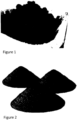
Figure 1 is a photo of a CNT nanocarbon mixture containing carbon nanotubes (CNTs) prior to crushing or grinding; -
Figure 2 is a photo of the CNT nanocarbon mixture following crushing or grinding into a coarse powder; -
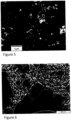
Figure 3 is a TEM (transmission electron microscopy) photo, with a 10,000nm scale shown in the lower right hand corner, of a CNT/amorphous carbon bundle and a few, long individual tubes in the CNT nanocarbon mixture, with the tube lengths varying from <200nm to >20,000nm; -
Figure 4 is a TEM photo, with a 2000nm scale shown in the lower right hand corner, of a CNT/nanocarbon bundle in the CNT nanocarbon mixture with the finely ground bundles typically ranging from 5µm to 1500µm; -
Figure 5 is a SEM (scanning electron microscopy) photo, with a 1µm scale shown in the lower left hand corner, which provides a closer view of the surfaces and 3D structures on a nanocarbon bundle in the CNT nanocarbon mixture; -
Figure 6 is a TEM photo, with a 500nm scale shown in the lower right hand corner, showing CNTs in the CNT nanocarbon mixture having hollow cores and many defects, such as bends, twists, and bamboo sections; -
Figure 7 is a SEM photo, with a 1µm scale shown in the lower left hand corner, showing in addition to CNTs clusters of amorphous carbon included in the CNT nanocarbon mixture; -
Figure 8 is a SHIM (scanning helium ion microscopy) photo, with a 1.50 µm field of view, a working distance of 11.9 mm, a scale of 200nm shown in the lower middle, an Acceleration V of 29.8 kV, a Dwell Time of 3.0µs, a Magnification (4x5 Polaroid) of 76.200X, and a Blanker Current of 0.5pA, showing surfaces of CNTs in the CNT nanocarbon mixture with much better focus and depth of field than SEM; -
Figure 9 is a TEM photo, with a 100nm scale shown in the lower right hand corner, showing the hollow structure of CNTs in the CNT nanocarbon mixture at high magnification, with the dark spots comprising catalyst particles; -
Figure 10 is a TEM photo, with a 20nm scale shown in the lower right hand corner, with the image grainy, but with individual tube walls (layers) in CNTs in the CNT nanocarbon mixture shown; -
Figure 11 is a TEM photo, with a 50nm scale shown in the lower right hand corner, showing a darker, peanut shaped object, which is a catalyst particle encapsulated in carbon layers at the end of a CNT; -
Figure 12 is a TEM photo, with a 20nm scale shown in the lower right hand corner, showing the same catalyst particle as shown inFigure 11 but with individual graphitic carbon walls (layers) shown; -
Figure 13 is a TEM photo, with a 10nm scale shown in the lower right hand corner, showing another CNT at the highest magnification, with the end of the CNT appearing to be closed but without a catalyst particle; -
Figure 14 is a TEM photo, with a 5nm scale shown in the lower left hand corner, showing a nanocarbon particle in the CNT nanocarbon mixture with some graphitic internal structure, but not specifically a hollow CNT or strictly amorphous; -
Figure 15 is a broad Raman spectrum for a typical CNT nanocarbon mixture produced using a heated reactor and catalytic decomposition of a hydrocarbon feed gas; -
Figure 16 is a close up view of the D and G mode peaks of the Raman spectrum ofFigure 15 ; -
Figure 17 is a photo of a raw, bulk CNF nanocarbon mixture containing carbon nanofibers (CNFs) prior to crushing or grinding; -
Figure 18 is a SEM photo, with a 1µm scale shown in the upper center, showing a bundle of CNFs in the CNF nanocarbon mixture ofFigure 17 ; -
Figure 19 is a TEM photo, with a 1000nm scale shown in the lower right hand corner, showing no hollow structure in the CNFs ofFigure 18 ; -
Figure 20 , with a 200nm scale shown in the lower right hand corner, is a TEM photo showing the "stacked cups" internal structure of the CNFs ofFigure 18 obtained with a higher magnification; -
Figure 21 is a TEM photo, with a 200nm scale shown in the lower right hand corner, showing CNF/amorphous nanocarbon clumps in the CNF nanocarbon mixture ofFigure 17 ; -
Figure 22 is a TEM photo showing CNF nanocarbon fibers, which commonly have non-uniform diameters and a wide range of lengths, in the CNF nanocarbon mixture ofFigure 17 ; -
Figure 23 is a broad Raman spectrum for a typical CNF nanocarbon mixture produced using a heated reactor and catalytic decomposition of a hydrocarbon feed gas; and -
Figure 24 is a schematic of a system for producing the nanocarbon mixtures ofFigures 1-24 . - As used herein, the term "concrete" means a material in either a cured or an uncured state that includes cement (with or without supplementary cementing materials, such as blast furnace slag, fly ash, limestone fines, and silica fume), mineral aggregate sand and stones, and water. The term "cement" means hydratable cement such as Portland cement produced from clinker containing hydraulic calcium silicates. The term "supplementary cementing" or "cementitious" means materials that form a plastic paste when mixed with a liquid, which harden and function as a glue or binder for holding the composite concrete material together. Cementitious materials form a hard matrix to bind aggregates and contribute to the properties of hardened concrete through hydraulic or pozzolanic activity. While Portland cement is a common concrete matrix material, alternative examples include, but not limited to, various limes and mortars, fly ashes, ground blast-furnace slag, and silica fume. The term "admixture" means ingredients added to concrete before or during mixing. The term "superplasticizer" means a surfactant used to uniformly disperse particles in uncured concrete.
- As used herein, the term "nanocarbon particle" means a particle comprising an allotrope of carbon with one or more particle dimensions on the order of 500 nanometers (nm) or less. "Nanotubes" mean cylindrical nanostructures comprising one or more cylindrical tubes of atoms having a high length to diameter ratio. Nanotubes can be categorized as single-walled nanotubes (SWNTs) or multi-walled nanotubes (MWNTs). "Nanotube particles" comprise individual molecules, particles, or agglomerates of particles comprised of nanotubes. "Nanofibers" means cylindrical nanostructures with a high length to diameter ratio, with atomic layers in a stacked plate, cup, or cone configuration. "Nanofiber particles" comprise individual molecules, particles, or agglomerates of particles comprised of nanofibers. "Graphene" means small particles of a two-dimensional hexagonal lattice of carbon atoms. Graphene is the basic structure of many other allotropes of carbon, including carbon nanotubes, carbon nanofibers, graphite, and other fullerenes. "Graphite" means a carbon crystalline atomic structure comprised of layers of graphene. "Carbon black" means a fine powder comprised of nanometer scale particles and agglomerates with an "amorphous" paracrystalline or polycrystalline atomic structure, usually made from decomposition and incomplete combustion of hydrocarbon feedstocks, but for the purposes of this disclosure, "carbon black" also includes finely-ground charcoal, coal, or activated carbon materials. "Nanodiamonds" means nanometer scale particles of a carbon allotrope with diamond crystal atomic structure. "Fullerene" means molecules or particles comprised of graphitic crystalline structures with defects in the hexagonal atomic lattice that bend or curve the layer(s) into spheres ("onions"), buds, cones, horns, tubes, or other composite shapes built from sub-structures with these simpler forms. "Nano-silica" means silica material with one or more particle dimensions on the order of 500 nanometers (nm) or less.
- Referring to
Figure 1 , a nanocarbon mixture containing a selected percentage range of CNTs is shown in raw, bulk form following production using a heated reactor and catalytic decomposition of a hydrocarbon feed gas. The nanocarbon mixture comprises CNTs containing defects as well as other amorphous forms of nanocarbon as well as catalyst particles. Typically, the CNTs comprise multi walled CNTs (MWCNTs) but can also include single walled CNTs (SWCNTs). In addition, the CNTs can occur in bundles of CNTs entrained in amorphous carbon structures. The nanocarbon mixture has the texture of powder but includes large clumps and agglomerates of carbon material such as bundles containing CNTs and amorphous carbon. - Referring to
Figure 2 , the nanocarbon mixture is shown following grinding into a carbon powder. As will be further described, the carbon powder facilitates dispersion of the nanocarbon mixture in a water/surfactant mixture. - Referring to
Figure 3 , a CNT/amorphous carbon bundle and a few, long individual tubes in the nanocarbon mixture are shown, with diameters <100nm and tube lengths varying from <200nm to >20,000nm. - Referring to
Figure 4 , a CNT/nanocarbon bundle in the nanocarbon mixture is shown with the finely ground bundles typically ranging from 5µm to 1500µm. - Referring to
Figure 5 , a closer view of the surfaces and 3D structures on a nanocarbon bundle in the nanocarbon mixture is shown. - Referring to
Figure 6 , CNTs in the nanocarbon mixture are shown having hollow cores and many defects, such as bends, twists, and bamboo sections. - Referring to
Figure 7 , clusters of amorphous carbon included in the nanocarbon mixture are shown. - Referring to
Figure 8 , surfaces of CNTs in the nanocarbon mixture are shown. - Referring to
Figure 9 , the hollow structure of CNTs in the nanocarbon mixture are shown at high magnification with the dark spots comprising catalyst particles. - Referring to
Figure 10 , individual tube walls (layers) in CNTs in the nanocarbon mixture are shown. - Referring to
Figure 11 , a catalyst particle encapsulated in carbon layers at the end of a CNT in the nanocarbon mixture is shown. - Referring to
Figure 12 , the same catalyst particle as shown inFigure 11 is shown but with individual graphitic carbon walls (layers) shown. - Referring to
Figure 13 , another CNT in the nanocarbon mixture is shown, with the end of the CNT appearing to be closed but without a catalyst particle. - Referring to
Figure 14 , a nanocarbon particle in the nanocarbon mixture is shown with some graphitic internal structure, but not specifically a hollow CNT or strictly amorphous. - Referring to
Figure 15 , a broad Raman spectrum is shown for a typical nanocarbon mixture produced using a heated reactor and catalytic decomposition of a hydrocarbon feed gas.Figure 16 is a close up view of the D and G mode peaks of the Raman spectrum. In this application, Raman spectroscopy was used to characterize the nanocarbon particles in the nanocarbon mixture. In particular, Raman spectroscopy was used to verify that the nanocarbon mixture contains multiwall nanotubes, primarily comprised of carbon arranged in a graphitic crystal structure, along with other "amorphous" carbon. - In
Figures 15 and16 , the second major peak at ~1590 1/cm ("G mode") shows that a slight majority of the carbon structure is graphitic (CNTs). The first major peak at ~1360 1/cm ("D mode") indicates that tube defects and amorphous carbon forms are also present in the nanocarbon mixture. The area of the D peak relative to the G peak shows that defects and amorphous carbon atomic structures are quite common in this carbon multiwall nanotube sample, as verified by the TEM images above. A small "peak" from ~200 1/cm to ~500 1/cm (radial breathing mode, or RBM) is indicative of the wide range of tube diameters in the sample. The third major peak at ~2720 1/cm (G' mode) is the second harmonic of the D mode peak, which is not very useful for characterization of this product, so it is omitted for the close-up of the D and G peaks shown inFig. 16 . The Raman spectrum shown inFigures 15 and16 indicates that the nanocarbon mixture contains about 50-60% CNTs. The remainder of the nanocarbon particles, which are less than about 50% of the total number of nanocarbon particles, are not in pure graphitic form. By way of example, the nanocarbon particles can comprise from 43% to 58% by mass of CNTs. As another example, the nanocarbon particles comprise from 30% to 50% by mass of CNTs. - Referring to
Figure 17 , a raw, bulk nanocarbon mixture containing carbon nanofibers (CNFs) is shown. The CNF nanocarbon mixture was produced using a heated reactor and catalytic decomposition of a hydrocarbon feed gas and contains a selected percentage range of CNFs. The nanocarbon mixture comprises CNFs containing defects as well as other amorphous forms of nanocarbon. - The CNF nanocarbon mixture has the texture of powder but includes large clumps and agglomerates of carbon material. As with the nanocarbon mixture shown in
Figure 2 , the CNF nanocarbon mixture can also be crushed or ground into a powder (not shown). While also generally cylindrical in shape, CNFs differ from CNTs because their structure is comprised of stacked disks, cones or cups of generally graphitic sheets of carbon atoms. CNFs typically have a larger average diameter and shorter average length than CNTs, as well. - Referring to
Figure 18 , a bundle of CNFs in the CNF nanocarbon mixture is shown. As shown inFigure 19 , the CNFs do not have a hollow interior structure. As shown inFigure 20 , the CNFs have a "stacked cups" internal structure. InFigure 21 , CNF/amorphous nanocarbon clumps are shown in the nanocarbon mixture.Figure 22 shows the CNF/nanocarbon fibers with non-uniform diameters and lengths. - Referring to
Figure 23 , Raman spectroscopy can be used to verify that the CNF nanocarbon mixture contains carbon nanofibers (CNFs), which are primarily comprised of the stacked plates, cones, or cups of carbon arranged in layers of a graphite (hexagonal) crystal structure, along with other "amorphous" carbon.Figure 23 is a typical Raman spectrum for the CNF nanocarbon mixture. The second major peak at the ~1590 1/cm ("G mode) shows that much of the carbon structure is graphitic (CNFs). The first major peak at ~1360 1/cm ("D mode") indicates that defects in the stacked layers of the fibers and amorphous carbon forms are the majority of the CNF/nanocarbon product composition. The Raman spectrum shown inFigure 23 indicates that the CNF nanocarbon mixture contains about 30-50% CNFs and more than about 50% is not in pure graphitic form. By way of example, the nanocarbon particles can comprise from 43% to 58% by mass of CNFs. As another example, the nanocarbon particles comprise from 30% to 50% by mass of CNFs. - Referring to
Figure 24 , asystem 10 and method for making the CNT nanocarbon mixture or the CNF nanocarbon mixture are illustrated schematically. In the illustrative embodiment, thesystem 10 is configured to perform a batch process, but can alternately be configured to continuously produce the CNF nanocarbon mixture. Thesystem 10 includes a hydrocarbonfeed gas supply 12 configured to supply ahydrocarbon feed gas 14. Thehydrocarbon feed gas 14 can comprise pure methane or natural gas obtained from a "fossil fuel" deposit. Natural gas is typically about 90% methane, along with small amounts of ethane, propane, higher hydrocarbons, and "inerts" like carbon dioxide or nitrogen. Alternately, thehydrocarbon feed gas 14 can comprise a higher order hydrocarbon such as ethylene or propane. In addition, the hydrocarbonfeed gas supply 12 can comprise a tank (or a pipeline) configured to supply thehydrocarbon feed gas 14 at a selected temperature, pressure, and flow rate. By way of example the temperature of thehydrocarbon feed gas 14 can be from 600 to 900°C, the pressure can be from 0.0123 to 0.0615 atmospheres and the flow rate can be from 0.05 to 3.0 liter/minute per gram of catalyst. - The
system 10 also includes areactor 16 comprising a hollow reactor cylinder having asealable inlet 22, areaction chamber 20 in fluid communication with theinlet 22, and asealable outlet 24 in fluid communication with thereaction chamber 20 adapted to discharge thenanocarbon mixture 38, which can comprise a nanocarbon mixture having the composition shown inFigure 15 , or a CNF nanocarbon mixture having the composition shown inFigure 23 , depending on the process parameters. In addition to thenanocarbon mixture 38, the method produces aproduct gas 34 comprised of hydrogen and unreacted hydrocarbon feed gas. For performing the method, thereaction chamber 20 can be heated by thermal combustion or electricity to a temperature of from 600 to 900°C. In addition, thereaction chamber 20 can be in fluid communication with aninert gas supply 28. - The
system 10 can also includes acatalyst transport system 18 adapted to move ametal catalyst 30 through thereaction chamber 20 in contact with thehydrocarbon feed gas 14 to produce thenanocarbon mixture 38 and theproduct gas 28. Thecatalyst transport system 18 can be in the form of a chain conveyor system, a rotating auger system, a high velocity pneumatic system or a plunger system. In any case, thecatalyst transport system 18 is adapted to move a selected amount of themetal catalyst 30 through thereaction chamber 20 at a rate dependent on the flow rate of thehydrocarbon feed gas 14. For example, with the flow rate of thehydrocarbon feed gas 14 between 0.05 and 3.0 liters/minute, the selected amount of themetal catalyst 30 can be about one gram/minute. Alternately, rather than acatalyst transport system 18, themetal catalyst 30 can be simply placed in thereaction chamber 20. - The
metal catalyst 30 can be provided in the form of particles. A preferred metal for themetal catalyst 30 comprises Ni, or an alloy containing Ni. For example, the metal can comprise NiAl, or Ni alloyed with Cu, Pd, Fe, Co, or an oxide such as MgO, ZnO, Mo2O3 or SiO2. However, rather than Ni or an alloy thereof, themetal catalyst 30 can comprise another metal, such as a metal selected from group VIII of the periodic table including Fe, Co, Ru, Pd and Pt. - The
system 10 also includes acarbon separator 40 adapted to separate thenanocarbon mixture 38 from theproduct gas 34 via gravity or cyclonic separation. Thesystem 10 can also include a high energy mixer (not shown) configured to mix thenanocarbon mixture 38 with water and a superplasticizer surfactant to form the liquid admixture. The high energy mixer can also be used to mix a nano-silica based compound for long-term stability of the suspended nanocarbon particles in the liquid admixture. Suitable high energy mixers can include one or more of the following: high-shear rotating mixers, such as pumps and turbines, rotor/stator mixers, and blade dispersers; mechanical grinding and impact-type mixers, such as attritors, ball mills, and hammer mills; and high pressure fluidic mixing devices, such as nozzles, orifices, and high-velocity impact devices, such as homogenizer pumps, valves and similar equipment. - By utilizing different compositions for the
metal catalyst 32, and by controlling process parameters, the process can be used to produce thenanocarbon mixture 38 with the desired types of particles and mass percentages in thenanocarbon mixture 38. During continuous production of thenanocarbon mixture 38 the amount of hydrogen in a methane/natural gas hydrocarbonfeed stock gas 14 remains fairly constant in the range from 10-80% by volume, depending on the material being produced. When using higherhydrocarbon feedstock gas 14 such as ethylene or propane, more carbon production can be expected with less hydrogen in theproduct gas 34. For example, for obtaining a nanocarbon mixture, the method can be controlled to provide approximately from about 20:1 to 40:1 carbon to catalyst mass ratio. For obtaining a CNF nanocarbon mixture, the method can be controlled to provide from about 200:1 to 500:1 carbon to catalyst mass ratio. - During the wetting and mixing step a predetermined quantity of the nanocarbon mixture in carbon powder form is mixed with a predetermined quantity of water/surfactant mixture with intense, high energy, large scale mixing equipment. Exemplary quantities of the nanocarbon mixture, superplasticizer surfactant, nano-silica based compound and water in the admixture include: nanocarbon mixture 0.4% to 1.9% mass percentage of total mass of admixture,
superplasticizer surfactant 2% to 9% mass percentage of total mass of admixture, nano-silica basedcompound 5% to 21% mass percentage of total mass of admixture, and water 57% to 93% mass percentage of total mass of admixture. During the wetting and mixing step, an organic compound including a functional group that contains a basic nitrogen atom with a lone pair can also be mixed into the admixture to increase early and/or late strength development in the concrete. A representative dosage can be from 0.5 to 20% by mass of the admixture. - The system and method can also be configured to produce, co-produce or mix in other forms of nanocarbon (e.g., graphene particles, graphite particles, carbon black, and "amorphous" paracrystalline and polycrystalline carbon particles, nanodiamonds, and single-layer and multi-layer fullerene particles) in a desired ratio (e.g., 50/50 mix by mass). In addition, the system and method utilize high-intensity mixing to de-agglomerate the nanocarbon particles in the water based admixture. Further, the system and method utilize a surfactant, known in the concrete industry as a water reducer or superplasticizer, to keep he nanocarbon particles dispersed in the liquid admixture. Still further, the system and method can utilize a compound with nano-silica, such as silica fume, in the admixture to keep the nanocarbon particles in suspension for relatively long-term storage and distribution of the admixture.
- A method for making concrete includes the steps of providing the admixture and then mixing the admixture with water, cement (with or without supplementary cementitious materials), and mineral aggregates in selected quantities.
- TABLE 1 identifies the ingredients of a sample concrete made using the admixture. TABLE 2 illustrates ASTM C494 test results for sample concretes made using the admixture, with the admixture identified under the trademark EDENCRETE. By varying the dosage of the admixture, and the amount of cementitious material, a desired ratio of the different nanocarbon particles to cementitious material in the cured concrete can be obtained. Preferably, these quantities are controlled to provide a range of CNT/total cementitious material for a CNT admixture of from 0.0002% to 0.0199% by mass, and/or CNF/total cementitious material for a CNF admixture, of from 0.0002% to 5% by mass.
TABLE 1 Based upon a concrete unit weight of 4100 lbs./yd.3 (2433 kg/m3) Material Notes Min. % wt. per yd3 Max. % wt. per yd3 (per 0.6 m3) Water corresponding to water/cementitious = 0.25 - 0.60 1.22 16.10 Cement 4.88 21.95 Sand 24.39 31.71 Rock 36.59 43.90 Silica Fume 3-5%, replacement by weight of cement 0.15 0.66 Fly Ash 10-30%, replacement by weight of cement 0.49 6.59 Slag 10-70%, replacement by weight of cement 0.49 15.37 Admixtures Min. % wt. per Yd3 Max. % wt. per Yd3 (per 0,6 m3) Type A 2-5 oz./cwt 0.0064 0.088 Low Range Water Reducer Type A 4-8 oz/cwt 0.012 0.14 Mid-Range Water Reducer Type B 2-4 oz/cwt 0.0064 0.07 Retarders Traditional Sugar-based Type B 2-6 oz/cwt 0.0064 0.11 Retarders Hydration Stabilizers Type C Accelerators Calcium 1%; 7-10 oz/cwt 0.022 0.18 Type C Accelerators Non-Calcium 1%; 12-16 oz/cwt 0.038 0.28 Type D Water reducing and retarding N/A - - Type E N/A - - Type F HRWRA 7-15 oz/cwt 0.022 0.27 Type G obsolete - - Type S SRA & CNI 0.25-3 gpy 0.003 0.04 1 oz/cwt is equal to 0,56 g/kg.1 gpy is equal to 0,07 g/m. TABLE 2 EdenCrete™ ASTM C494 Results % Increase Over Reference; Dosage = 3.5 gpy Age (Days) TEST 1 3 7 28 56 90 180 365 Compressive 37% 25% 35% 39% 41% 41% 39% 38% Strength (ASTMC39) Flexural Strength (ASTM C78) 25% 19% 32% Split-tensile Strength (ASTM C496) 29% 22% Abrasion Resistance (ASTM C779 Proc C) 62% 61% Length of Change (ASTM C157; Shrinkage) 39% reduction Time of Set (ASTM C403) Reduced: Initial Set 3 min, Final Set 4 minFreeze/Thaw enhancement Resistance (ASTM C666) Reference = 88.0, EdenCrete = 96.4; 9.55% Program Complete EdenCrete™ successfully conforms to the ASTM C494 Specification for Type S chemical admixtures used in concrete. - While a number of exemplary aspects and embodiments have been discussed above, those of skill in the art will recognize certain modifications, permutations, additions and subcombinations thereof.
Claims (15)
- A method for making an admixture in liquid form for concrete comprising:providing a nanocarbon mixture as a carbon powder comprising at least two different types of nanocarbon particles selected from the group consisting of carbon nanotube particles, carbon nanofiber particles, graphene particles, graphite particles, carbon black, "amorphous" paracrystalline carbon particles, polycrystalline carbon particles, nanodiamonds, single-layer fullerene particles, and multi-layer fullerene particles;wetting and mixing the carbon powder into a water/surfactant mixture comprised of water and a surfactant configured to de-agglomerate and uniformly disperse the nanocarbon particles in the water/surfactant mixture containing the carbon powder configured for addition to a concrete material comprising a cementitious material,blending the nanocarbon mixture with a nano-silica based compound, wherein quantities of the nanocarbon mixture, superplasticizer surfactant, nano-silica based compound and water in the admixture are:nanocarbon mixture 0.4% to 1.9% mass percentage of total mass of admixture,superplasticizer surfactant 2% to 9% mass percentage of total mass of admixture,nano-silica based compound 5% to 21% mass percentage of total mass of admixture,and water 57% to 93% mass percentage of total mass of admixture.
- The method of claim 1, wherein the nanocarbon mixture is blended with a nano-silica based compound either before or after the wetting and mixing step, the nano-silica based compound configured to stabilize the nanocarbon particles in the water/surfactant mixture.
- The method of claim 1, further comprising blending the nanocarbon mixture with an organic compound including a functional group that contains a basic nitrogen atom with a lone pair
- The method of claim 1, wherein the providing the nanocarbon mixture step comprises producing the nanocarbon mixture using a heated reactor and catalytic decomposition of a hydrocarbon feed gas, with a catalyst and reaction conditions in the reactor selected to provide the different types of nanocarbon particles and the predetermined mass percentage range of the nanocarbon particles.
- The method of claim 1, wherein the desired ratio of the nanocarbon particles to the cementitious material is from 0.0002% by mass to 0.0199% by mass.
- The method of claim 1 further comprising, following a crushing or grinding step, storing and then transporting the carbon powder.
- The method of claim 1, wherein the wetting and mixing step is performed using a mixer selected from the group consisting of high-shear rotating mixers, mechanical grinding and impact-type mixers, and high pressure fluidic mixing devices.
- The method of claim 1 further comprising, following the wetting and mixing step, storing the admixture for specific quality control testing.
- The method of claim 1 further comprising, following the wetting and mixing step, packaging the admixture in a container for single-use or bulk sales and distribution.
- The method of claim 1, wherein the nanocarbon particles comprise 43% to 58% by mass of carbon nanotube particles.
- The method of claim 1, wherein the nanocarbon particles comprise 30% to 50% by mass of carbon nanofiber particles.
- An admixture in liquid form for making concrete comprising:a suspension of uniformly dispersed nanocarbon particles in a water/surfactant mixture, including at least two different types of particles selected from the group consisting of carbon nanotube particles, carbon nanofiber particles, graphene particles, graphite particles, carbon black, "amorphous" paracrystalline carbon particles, polycrystalline carbon particles, nanodiamonds, single-layer fullerene particles, and multi-layer fullerene particles, with the carbon nanoparticles having a predetermined percentage range of from 0.4% to 1.9% of a total mass of the admixture;a nano-silica-based suspension stabilizer configured to improve the long term stability of the suspension of nanocarbon particles in the liquid admixture having a mass percentage of from 5% to 21% of a total mass of the admixture; water 57% to 93% mass percentage of total mass of admixture anda superplasticizer surfactant configured to facilitate dispersion of the nanocarbon particles having a percentage range by mass of the admixture of from 2% to 9%.
- The admixture of claim 12, further comprising an organic compound including a functional group that contains a basic nitrogen atom with a lone pair, having a percentage range from 0.5 to 20% by mass of the admixture.
- The admixture of claim 12, wherein the nanocarbon particles comprise 43% to 58% of carbon nanotube particles based on a total mass of the nanocarbon particles.
- The admixture of claim 12, wherein the nanocarbon particles comprise 30% to 50% of carbon nanofiber particles based on a total mass of the nanocarbon particles.
Applications Claiming Priority (2)
| Application Number | Priority Date | Filing Date | Title |
|---|---|---|---|
| US15/597,198 US10584072B2 (en) | 2017-05-17 | 2017-05-17 | Methods and systems for making nanocarbon particle admixtures and concrete |
| PCT/US2018/028054 WO2018212889A2 (en) | 2017-05-17 | 2018-04-18 | Methods and systems for making nanocarbon particle admixtures and concrete |
Publications (3)
| Publication Number | Publication Date |
|---|---|
| EP3625184A2 EP3625184A2 (en) | 2020-03-25 |
| EP3625184A4 EP3625184A4 (en) | 2021-03-24 |
| EP3625184B1 true EP3625184B1 (en) | 2023-07-12 |
Family
ID=64270349
Family Applications (1)
| Application Number | Title | Priority Date | Filing Date |
|---|---|---|---|
| EP18801609.1A Active EP3625184B1 (en) | 2017-05-17 | 2018-04-18 | Nanocarbon particle admixtures and method for making them |
Country Status (6)
| Country | Link |
|---|---|
| US (3) | US10584072B2 (en) |
| EP (1) | EP3625184B1 (en) |
| KR (1) | KR102536244B1 (en) |
| AU (1) | AU2018268799B2 (en) |
| CA (2) | CA3062758C (en) |
| WO (1) | WO2018212889A2 (en) |
Cited By (1)
| Publication number | Priority date | Publication date | Assignee | Title |
|---|---|---|---|---|
| WO2025147548A1 (en) * | 2024-01-02 | 2025-07-10 | NZT Group Inc. | High-performance concrete and admixtures |
Families Citing this family (24)
| Publication number | Priority date | Publication date | Assignee | Title |
|---|---|---|---|---|
| US10584072B2 (en) | 2017-05-17 | 2020-03-10 | Eden Innovations Ltd. | Methods and systems for making nanocarbon particle admixtures and concrete |
| US10472240B2 (en) | 2017-08-01 | 2019-11-12 | Eden Innovations Ltd. | Methods for making nanostructured materials using intercalation of carbon nanoparticles |
| US12365625B2 (en) * | 2019-03-12 | 2025-07-22 | H Quest Vanguard, Inc. | Nanocarbon material and applications of nanocarbon material |
| KR102212288B1 (en) * | 2019-06-24 | 2021-02-05 | 주식회사 남평레미콘 | Exothermic Concrete using Liquid Carbon Nanotubes and Manufacturing Method |
| KR102212289B1 (en) * | 2019-06-24 | 2021-02-05 | 주식회사 남평레미콘 | Remitar composition for manufacturing exothermic concrete and Method of exothermic concrete using the remitar composition |
| US11999654B2 (en) * | 2019-08-22 | 2024-06-04 | Eden Innovations Ltd. | Method for making concrete admixtures containing carbon nanoparticles |
| US20240116811A1 (en) * | 2019-10-14 | 2024-04-11 | C-Crete Technologies Llc | Cementitious composites via carbon-based nanomaterials |
| GB2589908B (en) * | 2019-12-12 | 2023-09-20 | Una Developments Ltd | A method for preparing a geoolymer composition |
| CN111393064A (en) * | 2020-03-26 | 2020-07-10 | 浙江和业科技有限公司 | Ultra-slow-release polycarboxylic acid pumping agent and preparation method thereof |
| US12017954B2 (en) * | 2020-09-11 | 2024-06-25 | Icon Technology, Inc. | 3D printable cementitious ink including electromagnetic pulse resistant binders |
| CN112479637A (en) * | 2020-10-28 | 2021-03-12 | 泰州利广瑞新材料科技有限公司 | Preparation method of nano carbon material |
| RU2750497C1 (en) * | 2020-11-23 | 2021-06-28 | Вадим Владимирович Потапов | Method for modifying concrete with complex additive including hydrothermal sio2 nanoparticles and multilayer carbon nanotubes |
| WO2022189026A1 (en) * | 2021-03-12 | 2022-09-15 | Harold Scholz & Co. Gmbh | Electrically conductive building material, in particular concrete, comprising an electrically conductive additive based on carbon fibres and graphite |
| WO2022189027A1 (en) * | 2021-03-12 | 2022-09-15 | Harold Scholz & Co. Gmbh | Electrically conductive building material, in particular concrete, comprising an electrically conductive graphite-based additive |
| WO2022265952A1 (en) * | 2021-06-15 | 2022-12-22 | Eden Innovations Ltd. | Method for making concrete and concrete structures having 3-dimensional carbon nanomaterial networks |
| RU2768884C2 (en) * | 2021-08-02 | 2022-03-25 | Григорий Иванович Яковлев | Complex additive for silicate composite materials and method for its preparation |
| US20230116160A1 (en) * | 2021-10-13 | 2023-04-13 | Chasm Advanced Materials, Inc. | Carbon Nanotube Hybrid Material for Concrete Applications |
| WO2023168263A1 (en) * | 2022-03-04 | 2023-09-07 | Lyten, Inc. | Cement compositions with 3d graphene carbons |
| CN115057672B (en) * | 2022-04-15 | 2023-08-15 | 重庆大学溧阳智慧城市研究院 | 3D printing conductive concrete based on nano graphite-nano SiO 2-copper slag |
| US20250368573A1 (en) | 2023-05-25 | 2025-12-04 | Blue Evolution Inc. | Ecofriendly biopolymer admixture for cement and concrete applications |
| CN117125709B (en) * | 2023-07-24 | 2024-06-14 | 深圳大学 | Carbon-fixing material and preparation method thereof, composite carbon-fixing material, carbon-fixing cement-based material |
| WO2025054564A2 (en) * | 2023-09-07 | 2025-03-13 | Lyten, Inc. | Cement and concrete compositions with 3d graphene carbons |
| WO2025128797A1 (en) | 2023-12-13 | 2025-06-19 | Blue Evolution, Inc | Ecofriendly, biodegradable biological polysaccharide composition for packaging materials |
| CN120271254A (en) * | 2025-04-02 | 2025-07-08 | 中建西部建设新疆有限公司 | Low-carbon cement and preparation method thereof |
Family Cites Families (32)
| Publication number | Priority date | Publication date | Assignee | Title |
|---|---|---|---|---|
| US4964917A (en) | 1986-08-26 | 1990-10-23 | Sandoz Ltd. | Methods and compositions for reclaiming concrete |
| US6298984B1 (en) | 1999-01-22 | 2001-10-09 | Einstone, Inc. | Packaging for deactivated cement and cement activator and procedure for mixing deactivated cement and cement activator therein |
| TW527332B (en) | 2000-05-19 | 2003-04-11 | Akzo Nobel Nv | Composition and method to prepare a concrete composition |
| JP3825336B2 (en) * | 2001-03-12 | 2006-09-27 | 双葉電子工業株式会社 | Nanocarbon production method and nanocarbon production apparatus |
| US6358310B1 (en) | 2001-06-14 | 2002-03-19 | W. R. Grace & Co.-Conn. | Air entraining admixture compositions |
| US6875417B1 (en) | 2001-10-24 | 2005-04-05 | University Of Kentucky Research Foundation | Catalytic conversion of hydrocarbons to hydrogen and high-value carbon |
| SG126710A1 (en) * | 2001-10-31 | 2006-11-29 | Univ Singapore | Carbon nanotubes fabrication and hydrogen production |
| JP4404961B2 (en) * | 2002-01-08 | 2010-01-27 | 双葉電子工業株式会社 | A method for producing carbon nanofibers. |
| WO2008016388A2 (en) * | 2006-01-30 | 2008-02-07 | Honda Motor Co., Ltd. | Method and apparatus for growth of high quality carbon single-walled nanotubes |
| US7744690B2 (en) | 2006-03-28 | 2010-06-29 | The United States Of America As Represented By The Secretary Of The Army | Blast-resistant concrete also suitable for limiting penetration of ballistic fragments |
| US8092778B2 (en) | 2007-01-24 | 2012-01-10 | Eden Energy Ltd. | Method for producing a hydrogen enriched fuel and carbon nanotubes using microwave assisted methane decomposition on catalyst |
| US7666327B1 (en) * | 2007-05-22 | 2010-02-23 | Oceanit Laboratories, Inc. | Multifunctional cementitious nanocomposite material and methods of making the same |
| US7713448B1 (en) | 2007-08-21 | 2010-05-11 | Oceanit Laboratories, Inc. | Carbon nanomaterial dispersion and stabilization |
| US7666915B2 (en) | 2007-09-24 | 2010-02-23 | Headwaters Technology Innovation, Llc | Highly dispersible carbon nanospheres in a polar solvent and methods for making same |
| US8865107B2 (en) * | 2008-02-08 | 2014-10-21 | Northwestern University | Highly concentrated nano-reinforcement suspensions for cementitious materials and method of reinforcing such materials |
| US9365456B2 (en) | 2008-02-08 | 2016-06-14 | Northwestern University | Highly-dispersed carbon nanotube-reinforced cement-based materials |
| US8408303B2 (en) * | 2009-09-24 | 2013-04-02 | Halliburton Energy Services, Inc. | Compositions for improving thermal conductivity of cement systems |
| MX2009013931A (en) | 2009-12-17 | 2011-06-16 | Urbanizaciones Inmobiliarias Del Ct S A De C V | Concrete reinforced with hybrid nanomaterials. |
| US8784557B2 (en) * | 2010-02-02 | 2014-07-22 | Pavement Surface Coatings, Llc | Pavement overlay material and method |
| KR100995154B1 (en) | 2010-02-11 | 2010-11-18 | 전남대학교산학협력단 | Method of preparing porous carbon nanofibers, porous carbon nanofibers thereby and applications including the same |
| US10049783B2 (en) * | 2010-02-19 | 2018-08-14 | Mike Foley | Utilizing nanoscale materials as dispersants, surfactants or stabilizing molecules, methods of making the same, and products produced therefrom |
| US20120189530A1 (en) * | 2011-01-20 | 2012-07-26 | Eden Energy Ltd. | System And Process For Producing Hydrogen And A Carbon Nanotube Product |
| US8871019B2 (en) * | 2011-11-01 | 2014-10-28 | King Abdulaziz City Science And Technology | Composition for construction materials manufacturing and the method of its production |
| US8759423B2 (en) | 2012-04-20 | 2014-06-24 | W. R. Grace & Co.-Conn. | Stabilized defoamers for cementitious compositions |
| SG11201500688XA (en) * | 2012-08-02 | 2015-02-27 | Amril Ag | Natural rubber containing nanocarbon |
| WO2014046734A1 (en) * | 2012-09-18 | 2014-03-27 | Brien Joshua V | Spall-resistant cementitious material |
| WO2014153570A2 (en) * | 2013-03-15 | 2014-09-25 | Transtar Group, Ltd | New and improved system for processing various chemicals and materials |
| JP6390024B2 (en) | 2014-04-08 | 2018-09-19 | 矢崎総業株式会社 | Carbon nanotube composite material and manufacturing method thereof |
| ES2561133B1 (en) | 2014-07-24 | 2016-12-01 | Alejandro Rodriguez Barros | MULTIFUNCTION OUTDOOR REAR VIEW MIRROR WITH LASER ISSUED DEVICE |
| CN105268339B (en) * | 2015-10-20 | 2018-04-24 | 深圳大学 | The preparation method of carbon nano tube dispersion liquid and carbon nanotubes cement-base composite material |
| WO2018103814A1 (en) | 2016-12-05 | 2018-06-14 | Art Carbon International Ag | Construction material composition comprising carbon nanotubes, stabilized aqueous carbon nanotube dispersion, and methods for the preparation thereof |
| US10584072B2 (en) | 2017-05-17 | 2020-03-10 | Eden Innovations Ltd. | Methods and systems for making nanocarbon particle admixtures and concrete |
-
2017
- 2017-05-17 US US15/597,198 patent/US10584072B2/en active Active
-
2018
- 2018-04-18 AU AU2018268799A patent/AU2018268799B2/en not_active Ceased
- 2018-04-18 CA CA3062758A patent/CA3062758C/en active Active
- 2018-04-18 EP EP18801609.1A patent/EP3625184B1/en active Active
- 2018-04-18 KR KR1020197035984A patent/KR102536244B1/en active Active
- 2018-04-18 CA CA3122974A patent/CA3122974C/en active Active
- 2018-04-18 WO PCT/US2018/028054 patent/WO2018212889A2/en not_active Ceased
-
2019
- 2019-12-20 US US16/722,288 patent/US11124458B2/en active Active
-
2021
- 2021-08-02 US US17/391,097 patent/US20210355041A1/en not_active Abandoned
Cited By (1)
| Publication number | Priority date | Publication date | Assignee | Title |
|---|---|---|---|---|
| WO2025147548A1 (en) * | 2024-01-02 | 2025-07-10 | NZT Group Inc. | High-performance concrete and admixtures |
Also Published As
| Publication number | Publication date |
|---|---|
| CA3062758C (en) | 2021-09-28 |
| US11124458B2 (en) | 2021-09-21 |
| CA3062758A1 (en) | 2018-11-22 |
| CA3122974C (en) | 2023-01-03 |
| US10584072B2 (en) | 2020-03-10 |
| AU2018268799B2 (en) | 2023-09-21 |
| US20210355041A1 (en) | 2021-11-18 |
| AU2018268799A1 (en) | 2019-12-19 |
| CA3122974A1 (en) | 2018-11-22 |
| KR20200045443A (en) | 2020-05-04 |
| KR102536244B1 (en) | 2023-05-24 |
| EP3625184A4 (en) | 2021-03-24 |
| EP3625184A2 (en) | 2020-03-25 |
| US20200140342A1 (en) | 2020-05-07 |
| WO2018212889A2 (en) | 2018-11-22 |
| US20180334407A1 (en) | 2018-11-22 |
| WO2018212889A3 (en) | 2019-08-01 |
Similar Documents
| Publication | Publication Date | Title |
|---|---|---|
| US11124458B2 (en) | Nanocarbon particle admixtures for concrete | |
| Cui et al. | Mechanical properties and reinforcing mechanisms of cementitious composites with different types of multiwalled carbon nanotubes | |
| Lu et al. | Carbon-based nanomaterials engineered cement composites: a review | |
| Bharj et al. | Experimental study on compressive strength of cement-CNT composite paste | |
| CN102884018B (en) | The concrete strengthened by mixing nano material | |
| JP7844056B2 (en) | Carbon nanotube hybrid materials for concrete applications | |
| US11999654B2 (en) | Method for making concrete admixtures containing carbon nanoparticles | |
| Yang et al. | Synthesis of uniformly dispersed carbon nanotube reinforcement in Al powder for preparing reinforced Al composites | |
| EP3548447B1 (en) | Construction material composition comprising carbon nanotubes and method for the preparation thereof | |
| Gao et al. | Dispersion of carbon nanotubes in aqueous cementitious materials: A review | |
| Khater et al. | Characterization of alkali activated geopolymer mortar doped with MWCNT | |
| Maurya et al. | Influence of physico‐mechanical and electrical resistivity performance of high volume fly‐ash cementitious mortar with low carbon | |
| Long | Design, performance, and mechanism of cement-based materials with 2D nanomaterials | |
| WO2025054564A2 (en) | Cement and concrete compositions with 3d graphene carbons | |
| Maurya et al. | Effect of highly dispersed hybrid carbon nanomaterials on the durability of high-volume fly ash based cementitious mortar | |
| CN115636647B (en) | Concrete based on micro-nano components and preparation method thereof | |
| WO2026102294A1 (en) | Cementitious materials including 3d graphene carbons | |
| Zhang et al. | A New Dispersion Strategy to Achieve High Performance Graphene-Based | |
| HK40111589A (en) | Carbon nanotube hybrid material for concrete applications | |
| WO2026097108A2 (en) | Carbon nanotube-metal oxide hybrid material for mortar and concrete | |
| Campillo et al. | Centre for Nanomaterials Applications in Construction (NANOC), Construction and | |
| Amjad et al. | SYNTHESIS AND DISPERSION MECHANISM OF NANOMATERIALS IN CEMENT-BASED COMPOSITES: A STATE-OF-THE-ART REVIEW | |
| Lu et al. | 1School of Civil Engineering, Harbin Institute of Technology, Harbin, PR China, 2Key Lab of Structures Dynamic Behavior and Control of the Ministry of Education (Harbin Institute of Technology), Harbin, PR China |
Legal Events
| Date | Code | Title | Description |
|---|---|---|---|
| STAA | Information on the status of an ep patent application or granted ep patent |
Free format text: STATUS: THE INTERNATIONAL PUBLICATION HAS BEEN MADE |
|
| PUAI | Public reference made under article 153(3) epc to a published international application that has entered the european phase |
Free format text: ORIGINAL CODE: 0009012 |
|
| STAA | Information on the status of an ep patent application or granted ep patent |
Free format text: STATUS: REQUEST FOR EXAMINATION WAS MADE |
|
| 17P | Request for examination filed |
Effective date: 20191211 |
|
| AK | Designated contracting states |
Kind code of ref document: A2 Designated state(s): AL AT BE BG CH CY CZ DE DK EE ES FI FR GB GR HR HU IE IS IT LI LT LU LV MC MK MT NL NO PL PT RO RS SE SI SK SM TR |
|
| AX | Request for extension of the european patent |
Extension state: BA ME |
|
| RAP1 | Party data changed (applicant data changed or rights of an application transferred) |
Owner name: EDEN INNOVATIONS LTD. |
|
| DAV | Request for validation of the european patent (deleted) | ||
| DAX | Request for extension of the european patent (deleted) | ||
| A4 | Supplementary search report drawn up and despatched |
Effective date: 20210223 |
|
| RIC1 | Information provided on ipc code assigned before grant |
Ipc: C04B 14/04 20060101ALI20210217BHEP Ipc: C04B 14/02 20060101AFI20210217BHEP |
|
| STAA | Information on the status of an ep patent application or granted ep patent |
Free format text: STATUS: EXAMINATION IS IN PROGRESS |
|
| 17Q | First examination report despatched |
Effective date: 20210914 |
|
| GRAP | Despatch of communication of intention to grant a patent |
Free format text: ORIGINAL CODE: EPIDOSNIGR1 |
|
| STAA | Information on the status of an ep patent application or granted ep patent |
Free format text: STATUS: GRANT OF PATENT IS INTENDED |
|
| INTG | Intention to grant announced |
Effective date: 20230210 |
|
| GRAS | Grant fee paid |
Free format text: ORIGINAL CODE: EPIDOSNIGR3 |
|
| GRAA | (expected) grant |
Free format text: ORIGINAL CODE: 0009210 |
|
| STAA | Information on the status of an ep patent application or granted ep patent |
Free format text: STATUS: THE PATENT HAS BEEN GRANTED |
|
| AK | Designated contracting states |
Kind code of ref document: B1 Designated state(s): AL AT BE BG CH CY CZ DE DK EE ES FI FR GB GR HR HU IE IS IT LI LT LU LV MC MK MT NL NO PL PT RO RS SE SI SK SM TR |
|
| REG | Reference to a national code |
Ref country code: CH Ref legal event code: EP |
|
| REG | Reference to a national code |
Ref country code: IE Ref legal event code: FG4D |
|
| REG | Reference to a national code |
Ref country code: DE Ref legal event code: R096 Ref document number: 602018053293 Country of ref document: DE |
|
| REG | Reference to a national code |
Ref country code: LT Ref legal event code: MG9D |
|
| REG | Reference to a national code |
Ref country code: NL Ref legal event code: MP Effective date: 20230712 |
|
| REG | Reference to a national code |
Ref country code: AT Ref legal event code: MK05 Ref document number: 1586989 Country of ref document: AT Kind code of ref document: T Effective date: 20230712 |
|
| PG25 | Lapsed in a contracting state [announced via postgrant information from national office to epo] |
Ref country code: NL Free format text: LAPSE BECAUSE OF FAILURE TO SUBMIT A TRANSLATION OF THE DESCRIPTION OR TO PAY THE FEE WITHIN THE PRESCRIBED TIME-LIMIT Effective date: 20230712 |
|
| PG25 | Lapsed in a contracting state [announced via postgrant information from national office to epo] |
Ref country code: GR Free format text: LAPSE BECAUSE OF FAILURE TO SUBMIT A TRANSLATION OF THE DESCRIPTION OR TO PAY THE FEE WITHIN THE PRESCRIBED TIME-LIMIT Effective date: 20231013 |
|
| PG25 | Lapsed in a contracting state [announced via postgrant information from national office to epo] |
Ref country code: ES Free format text: LAPSE BECAUSE OF FAILURE TO SUBMIT A TRANSLATION OF THE DESCRIPTION OR TO PAY THE FEE WITHIN THE PRESCRIBED TIME-LIMIT Effective date: 20230712 |
|
| PG25 | Lapsed in a contracting state [announced via postgrant information from national office to epo] |
Ref country code: IS Free format text: LAPSE BECAUSE OF FAILURE TO SUBMIT A TRANSLATION OF THE DESCRIPTION OR TO PAY THE FEE WITHIN THE PRESCRIBED TIME-LIMIT Effective date: 20231112 |
|
| PG25 | Lapsed in a contracting state [announced via postgrant information from national office to epo] |
Ref country code: SE Free format text: LAPSE BECAUSE OF FAILURE TO SUBMIT A TRANSLATION OF THE DESCRIPTION OR TO PAY THE FEE WITHIN THE PRESCRIBED TIME-LIMIT Effective date: 20230712 Ref country code: RS Free format text: LAPSE BECAUSE OF FAILURE TO SUBMIT A TRANSLATION OF THE DESCRIPTION OR TO PAY THE FEE WITHIN THE PRESCRIBED TIME-LIMIT Effective date: 20230712 Ref country code: PT Free format text: LAPSE BECAUSE OF FAILURE TO SUBMIT A TRANSLATION OF THE DESCRIPTION OR TO PAY THE FEE WITHIN THE PRESCRIBED TIME-LIMIT Effective date: 20231113 Ref country code: NO Free format text: LAPSE BECAUSE OF FAILURE TO SUBMIT A TRANSLATION OF THE DESCRIPTION OR TO PAY THE FEE WITHIN THE PRESCRIBED TIME-LIMIT Effective date: 20231012 Ref country code: LV Free format text: LAPSE BECAUSE OF FAILURE TO SUBMIT A TRANSLATION OF THE DESCRIPTION OR TO PAY THE FEE WITHIN THE PRESCRIBED TIME-LIMIT Effective date: 20230712 Ref country code: LT Free format text: LAPSE BECAUSE OF FAILURE TO SUBMIT A TRANSLATION OF THE DESCRIPTION OR TO PAY THE FEE WITHIN THE PRESCRIBED TIME-LIMIT Effective date: 20230712 Ref country code: IS Free format text: LAPSE BECAUSE OF FAILURE TO SUBMIT A TRANSLATION OF THE DESCRIPTION OR TO PAY THE FEE WITHIN THE PRESCRIBED TIME-LIMIT Effective date: 20231112 Ref country code: HR Free format text: LAPSE BECAUSE OF FAILURE TO SUBMIT A TRANSLATION OF THE DESCRIPTION OR TO PAY THE FEE WITHIN THE PRESCRIBED TIME-LIMIT Effective date: 20230712 Ref country code: GR Free format text: LAPSE BECAUSE OF FAILURE TO SUBMIT A TRANSLATION OF THE DESCRIPTION OR TO PAY THE FEE WITHIN THE PRESCRIBED TIME-LIMIT Effective date: 20231013 Ref country code: FI Free format text: LAPSE BECAUSE OF FAILURE TO SUBMIT A TRANSLATION OF THE DESCRIPTION OR TO PAY THE FEE WITHIN THE PRESCRIBED TIME-LIMIT Effective date: 20230712 Ref country code: ES Free format text: LAPSE BECAUSE OF FAILURE TO SUBMIT A TRANSLATION OF THE DESCRIPTION OR TO PAY THE FEE WITHIN THE PRESCRIBED TIME-LIMIT Effective date: 20230712 Ref country code: AT Free format text: LAPSE BECAUSE OF FAILURE TO SUBMIT A TRANSLATION OF THE DESCRIPTION OR TO PAY THE FEE WITHIN THE PRESCRIBED TIME-LIMIT Effective date: 20230712 |
|
| PG25 | Lapsed in a contracting state [announced via postgrant information from national office to epo] |
Ref country code: PL Free format text: LAPSE BECAUSE OF FAILURE TO SUBMIT A TRANSLATION OF THE DESCRIPTION OR TO PAY THE FEE WITHIN THE PRESCRIBED TIME-LIMIT Effective date: 20230712 |
|
| REG | Reference to a national code |
Ref country code: DE Ref legal event code: R097 Ref document number: 602018053293 Country of ref document: DE |
|
| PG25 | Lapsed in a contracting state [announced via postgrant information from national office to epo] |
Ref country code: SM Free format text: LAPSE BECAUSE OF FAILURE TO SUBMIT A TRANSLATION OF THE DESCRIPTION OR TO PAY THE FEE WITHIN THE PRESCRIBED TIME-LIMIT Effective date: 20230712 Ref country code: RO Free format text: LAPSE BECAUSE OF FAILURE TO SUBMIT A TRANSLATION OF THE DESCRIPTION OR TO PAY THE FEE WITHIN THE PRESCRIBED TIME-LIMIT Effective date: 20230712 Ref country code: EE Free format text: LAPSE BECAUSE OF FAILURE TO SUBMIT A TRANSLATION OF THE DESCRIPTION OR TO PAY THE FEE WITHIN THE PRESCRIBED TIME-LIMIT Effective date: 20230712 Ref country code: DK Free format text: LAPSE BECAUSE OF FAILURE TO SUBMIT A TRANSLATION OF THE DESCRIPTION OR TO PAY THE FEE WITHIN THE PRESCRIBED TIME-LIMIT Effective date: 20230712 Ref country code: CZ Free format text: LAPSE BECAUSE OF FAILURE TO SUBMIT A TRANSLATION OF THE DESCRIPTION OR TO PAY THE FEE WITHIN THE PRESCRIBED TIME-LIMIT Effective date: 20230712 Ref country code: SK Free format text: LAPSE BECAUSE OF FAILURE TO SUBMIT A TRANSLATION OF THE DESCRIPTION OR TO PAY THE FEE WITHIN THE PRESCRIBED TIME-LIMIT Effective date: 20230712 |
|
| PLBE | No opposition filed within time limit |
Free format text: ORIGINAL CODE: 0009261 |
|
| STAA | Information on the status of an ep patent application or granted ep patent |
Free format text: STATUS: NO OPPOSITION FILED WITHIN TIME LIMIT |
|
| PG25 | Lapsed in a contracting state [announced via postgrant information from national office to epo] |
Ref country code: IT Free format text: LAPSE BECAUSE OF FAILURE TO SUBMIT A TRANSLATION OF THE DESCRIPTION OR TO PAY THE FEE WITHIN THE PRESCRIBED TIME-LIMIT Effective date: 20230712 |
|
| 26N | No opposition filed |
Effective date: 20240415 |
|
| PGFP | Annual fee paid to national office [announced via postgrant information from national office to epo] |
Ref country code: GB Payment date: 20240423 Year of fee payment: 7 |
|
| PGFP | Annual fee paid to national office [announced via postgrant information from national office to epo] |
Ref country code: DE Payment date: 20240429 Year of fee payment: 7 |
|
| PG25 | Lapsed in a contracting state [announced via postgrant information from national office to epo] |
Ref country code: SI Free format text: LAPSE BECAUSE OF FAILURE TO SUBMIT A TRANSLATION OF THE DESCRIPTION OR TO PAY THE FEE WITHIN THE PRESCRIBED TIME-LIMIT Effective date: 20230712 |
|
| PGFP | Annual fee paid to national office [announced via postgrant information from national office to epo] |
Ref country code: FR Payment date: 20240419 Year of fee payment: 7 |
|
| PG25 | Lapsed in a contracting state [announced via postgrant information from national office to epo] |
Ref country code: BG Free format text: LAPSE BECAUSE OF FAILURE TO SUBMIT A TRANSLATION OF THE DESCRIPTION OR TO PAY THE FEE WITHIN THE PRESCRIBED TIME-LIMIT Effective date: 20230712 |
|
| PG25 | Lapsed in a contracting state [announced via postgrant information from national office to epo] |
Ref country code: MC Free format text: LAPSE BECAUSE OF FAILURE TO SUBMIT A TRANSLATION OF THE DESCRIPTION OR TO PAY THE FEE WITHIN THE PRESCRIBED TIME-LIMIT Effective date: 20230712 |
|
| PG25 | Lapsed in a contracting state [announced via postgrant information from national office to epo] |
Ref country code: MC Free format text: LAPSE BECAUSE OF FAILURE TO SUBMIT A TRANSLATION OF THE DESCRIPTION OR TO PAY THE FEE WITHIN THE PRESCRIBED TIME-LIMIT Effective date: 20230712 Ref country code: BG Free format text: LAPSE BECAUSE OF FAILURE TO SUBMIT A TRANSLATION OF THE DESCRIPTION OR TO PAY THE FEE WITHIN THE PRESCRIBED TIME-LIMIT Effective date: 20230712 |
|
| REG | Reference to a national code |
Ref country code: CH Ref legal event code: PL |
|
| PG25 | Lapsed in a contracting state [announced via postgrant information from national office to epo] |
Ref country code: LU Free format text: LAPSE BECAUSE OF NON-PAYMENT OF DUE FEES Effective date: 20240418 |
|
| REG | Reference to a national code |
Ref country code: BE Ref legal event code: MM Effective date: 20240430 |
|
| PG25 | Lapsed in a contracting state [announced via postgrant information from national office to epo] |
Ref country code: LU Free format text: LAPSE BECAUSE OF NON-PAYMENT OF DUE FEES Effective date: 20240418 |
|
| PG25 | Lapsed in a contracting state [announced via postgrant information from national office to epo] |
Ref country code: BE Free format text: LAPSE BECAUSE OF NON-PAYMENT OF DUE FEES Effective date: 20240430 |
|
| PG25 | Lapsed in a contracting state [announced via postgrant information from national office to epo] |
Ref country code: BE Free format text: LAPSE BECAUSE OF NON-PAYMENT OF DUE FEES Effective date: 20240430 Ref country code: CH Free format text: LAPSE BECAUSE OF NON-PAYMENT OF DUE FEES Effective date: 20240430 |
|
| PG25 | Lapsed in a contracting state [announced via postgrant information from national office to epo] |
Ref country code: IE Free format text: LAPSE BECAUSE OF NON-PAYMENT OF DUE FEES Effective date: 20240418 |
|
| PG25 | Lapsed in a contracting state [announced via postgrant information from national office to epo] |
Ref country code: CY Free format text: LAPSE BECAUSE OF FAILURE TO SUBMIT A TRANSLATION OF THE DESCRIPTION OR TO PAY THE FEE WITHIN THE PRESCRIBED TIME-LIMIT; INVALID AB INITIO Effective date: 20180418 |
|
| PG25 | Lapsed in a contracting state [announced via postgrant information from national office to epo] |
Ref country code: HU Free format text: LAPSE BECAUSE OF FAILURE TO SUBMIT A TRANSLATION OF THE DESCRIPTION OR TO PAY THE FEE WITHIN THE PRESCRIBED TIME-LIMIT; INVALID AB INITIO Effective date: 20180418 |
|
| REG | Reference to a national code |
Ref country code: DE Ref legal event code: R119 Ref document number: 602018053293 Country of ref document: DE |
|
| GBPC | Gb: european patent ceased through non-payment of renewal fee |
Effective date: 20250418 |
|
| PG25 | Lapsed in a contracting state [announced via postgrant information from national office to epo] |
Ref country code: DE Free format text: LAPSE BECAUSE OF NON-PAYMENT OF DUE FEES Effective date: 20251104 |
|
| PG25 | Lapsed in a contracting state [announced via postgrant information from national office to epo] |
Ref country code: GB Free format text: LAPSE BECAUSE OF NON-PAYMENT OF DUE FEES Effective date: 20250418 |
|
| PG25 | Lapsed in a contracting state [announced via postgrant information from national office to epo] |
Ref country code: FR Free format text: LAPSE BECAUSE OF NON-PAYMENT OF DUE FEES Effective date: 20250430 |