EP3625077B1 - Véhicule à machine motrice électrique optionnelle couplant une batterie non diversifiable à un chargeur - Google Patents
Véhicule à machine motrice électrique optionnelle couplant une batterie non diversifiable à un chargeur Download PDFInfo
- Publication number
- EP3625077B1 EP3625077B1 EP18735351.1A EP18735351A EP3625077B1 EP 3625077 B1 EP3625077 B1 EP 3625077B1 EP 18735351 A EP18735351 A EP 18735351A EP 3625077 B1 EP3625077 B1 EP 3625077B1
- Authority
- EP
- European Patent Office
- Prior art keywords
- charger
- driving machine
- coupled
- electric
- machine
- Prior art date
- Legal status (The legal status is an assumption and is not a legal conclusion. Google has not performed a legal analysis and makes no representation as to the accuracy of the status listed.)
- Active
Links
Images
Classifications
-
- B—PERFORMING OPERATIONS; TRANSPORTING
- B60—VEHICLES IN GENERAL
- B60L—PROPULSION OF ELECTRICALLY-PROPELLED VEHICLES; SUPPLYING ELECTRIC POWER FOR AUXILIARY EQUIPMENT OF ELECTRICALLY-PROPELLED VEHICLES; ELECTRODYNAMIC BRAKE SYSTEMS FOR VEHICLES IN GENERAL; MAGNETIC SUSPENSION OR LEVITATION FOR VEHICLES; MONITORING OPERATING VARIABLES OF ELECTRICALLY-PROPELLED VEHICLES; ELECTRIC SAFETY DEVICES FOR ELECTRICALLY-PROPELLED VEHICLES
- B60L15/00—Methods, circuits, or devices for controlling the traction-motor speed of electrically-propelled vehicles
- B60L15/007—Physical arrangements or structures of drive train converters specially adapted for the propulsion motors of electric vehicles
-
- B—PERFORMING OPERATIONS; TRANSPORTING
- B60—VEHICLES IN GENERAL
- B60K—ARRANGEMENT OR MOUNTING OF PROPULSION UNITS OR OF TRANSMISSIONS IN VEHICLES; ARRANGEMENT OR MOUNTING OF PLURAL DIVERSE PRIME-MOVERS IN VEHICLES; AUXILIARY DRIVES FOR VEHICLES; INSTRUMENTATION OR DASHBOARDS FOR VEHICLES; ARRANGEMENTS IN CONNECTION WITH COOLING, AIR INTAKE, GAS EXHAUST OR FUEL SUPPLY OF PROPULSION UNITS IN VEHICLES
- B60K1/00—Arrangement or mounting of electrical propulsion units
- B60K1/02—Arrangement or mounting of electrical propulsion units comprising more than one electric motor
-
- B—PERFORMING OPERATIONS; TRANSPORTING
- B60—VEHICLES IN GENERAL
- B60K—ARRANGEMENT OR MOUNTING OF PROPULSION UNITS OR OF TRANSMISSIONS IN VEHICLES; ARRANGEMENT OR MOUNTING OF PLURAL DIVERSE PRIME-MOVERS IN VEHICLES; AUXILIARY DRIVES FOR VEHICLES; INSTRUMENTATION OR DASHBOARDS FOR VEHICLES; ARRANGEMENTS IN CONNECTION WITH COOLING, AIR INTAKE, GAS EXHAUST OR FUEL SUPPLY OF PROPULSION UNITS IN VEHICLES
- B60K17/00—Arrangement or mounting of transmissions in vehicles
- B60K17/34—Arrangement or mounting of transmissions in vehicles for driving both front and rear wheels, e.g. four wheel drive vehicles
- B60K17/354—Arrangement or mounting of transmissions in vehicles for driving both front and rear wheels, e.g. four wheel drive vehicles having separate mechanical assemblies for transmitting drive to the front or to the rear wheels or set of wheels
-
- B—PERFORMING OPERATIONS; TRANSPORTING
- B60—VEHICLES IN GENERAL
- B60L—PROPULSION OF ELECTRICALLY-PROPELLED VEHICLES; SUPPLYING ELECTRIC POWER FOR AUXILIARY EQUIPMENT OF ELECTRICALLY-PROPELLED VEHICLES; ELECTRODYNAMIC BRAKE SYSTEMS FOR VEHICLES IN GENERAL; MAGNETIC SUSPENSION OR LEVITATION FOR VEHICLES; MONITORING OPERATING VARIABLES OF ELECTRICALLY-PROPELLED VEHICLES; ELECTRIC SAFETY DEVICES FOR ELECTRICALLY-PROPELLED VEHICLES
- B60L50/00—Electric propulsion with power supplied within the vehicle
- B60L50/10—Electric propulsion with power supplied within the vehicle using propulsion power supplied by engine-driven generators, e.g. generators driven by combustion engines
- B60L50/15—Electric propulsion with power supplied within the vehicle using propulsion power supplied by engine-driven generators, e.g. generators driven by combustion engines with additional electric power supply
-
- B—PERFORMING OPERATIONS; TRANSPORTING
- B60—VEHICLES IN GENERAL
- B60L—PROPULSION OF ELECTRICALLY-PROPELLED VEHICLES; SUPPLYING ELECTRIC POWER FOR AUXILIARY EQUIPMENT OF ELECTRICALLY-PROPELLED VEHICLES; ELECTRODYNAMIC BRAKE SYSTEMS FOR VEHICLES IN GENERAL; MAGNETIC SUSPENSION OR LEVITATION FOR VEHICLES; MONITORING OPERATING VARIABLES OF ELECTRICALLY-PROPELLED VEHICLES; ELECTRIC SAFETY DEVICES FOR ELECTRICALLY-PROPELLED VEHICLES
- B60L50/00—Electric propulsion with power supplied within the vehicle
- B60L50/50—Electric propulsion with power supplied within the vehicle using propulsion power supplied by batteries or fuel cells
- B60L50/60—Electric propulsion with power supplied within the vehicle using propulsion power supplied by batteries or fuel cells using power supplied by batteries
-
- B—PERFORMING OPERATIONS; TRANSPORTING
- B60—VEHICLES IN GENERAL
- B60L—PROPULSION OF ELECTRICALLY-PROPELLED VEHICLES; SUPPLYING ELECTRIC POWER FOR AUXILIARY EQUIPMENT OF ELECTRICALLY-PROPELLED VEHICLES; ELECTRODYNAMIC BRAKE SYSTEMS FOR VEHICLES IN GENERAL; MAGNETIC SUSPENSION OR LEVITATION FOR VEHICLES; MONITORING OPERATING VARIABLES OF ELECTRICALLY-PROPELLED VEHICLES; ELECTRIC SAFETY DEVICES FOR ELECTRICALLY-PROPELLED VEHICLES
- B60L53/00—Methods of charging batteries, specially adapted for electric vehicles; Charging stations or on-board charging equipment therefor; Exchange of energy storage elements in electric vehicles
- B60L53/10—Methods of charging batteries, specially adapted for electric vehicles; Charging stations or on-board charging equipment therefor; Exchange of energy storage elements in electric vehicles characterised by the energy transfer between the charging station and the vehicle
- B60L53/14—Conductive energy transfer
-
- B—PERFORMING OPERATIONS; TRANSPORTING
- B60—VEHICLES IN GENERAL
- B60L—PROPULSION OF ELECTRICALLY-PROPELLED VEHICLES; SUPPLYING ELECTRIC POWER FOR AUXILIARY EQUIPMENT OF ELECTRICALLY-PROPELLED VEHICLES; ELECTRODYNAMIC BRAKE SYSTEMS FOR VEHICLES IN GENERAL; MAGNETIC SUSPENSION OR LEVITATION FOR VEHICLES; MONITORING OPERATING VARIABLES OF ELECTRICALLY-PROPELLED VEHICLES; ELECTRIC SAFETY DEVICES FOR ELECTRICALLY-PROPELLED VEHICLES
- B60L53/00—Methods of charging batteries, specially adapted for electric vehicles; Charging stations or on-board charging equipment therefor; Exchange of energy storage elements in electric vehicles
- B60L53/20—Methods of charging batteries, specially adapted for electric vehicles; Charging stations or on-board charging equipment therefor; Exchange of energy storage elements in electric vehicles characterised by converters located in the vehicle
- B60L53/22—Constructional details or arrangements of charging converters specially adapted for charging electric vehicles
-
- B—PERFORMING OPERATIONS; TRANSPORTING
- B60—VEHICLES IN GENERAL
- B60L—PROPULSION OF ELECTRICALLY-PROPELLED VEHICLES; SUPPLYING ELECTRIC POWER FOR AUXILIARY EQUIPMENT OF ELECTRICALLY-PROPELLED VEHICLES; ELECTRODYNAMIC BRAKE SYSTEMS FOR VEHICLES IN GENERAL; MAGNETIC SUSPENSION OR LEVITATION FOR VEHICLES; MONITORING OPERATING VARIABLES OF ELECTRICALLY-PROPELLED VEHICLES; ELECTRIC SAFETY DEVICES FOR ELECTRICALLY-PROPELLED VEHICLES
- B60L2220/00—Electrical machine types; Structures or applications thereof
- B60L2220/40—Electrical machine applications
- B60L2220/42—Electrical machine applications with use of more than one motor
-
- B—PERFORMING OPERATIONS; TRANSPORTING
- B60—VEHICLES IN GENERAL
- B60L—PROPULSION OF ELECTRICALLY-PROPELLED VEHICLES; SUPPLYING ELECTRIC POWER FOR AUXILIARY EQUIPMENT OF ELECTRICALLY-PROPELLED VEHICLES; ELECTRODYNAMIC BRAKE SYSTEMS FOR VEHICLES IN GENERAL; MAGNETIC SUSPENSION OR LEVITATION FOR VEHICLES; MONITORING OPERATING VARIABLES OF ELECTRICALLY-PROPELLED VEHICLES; ELECTRIC SAFETY DEVICES FOR ELECTRICALLY-PROPELLED VEHICLES
- B60L2260/00—Operating Modes
- B60L2260/20—Drive modes; Transition between modes
- B60L2260/28—Four wheel or all wheel drive
-
- B—PERFORMING OPERATIONS; TRANSPORTING
- B60—VEHICLES IN GENERAL
- B60L—PROPULSION OF ELECTRICALLY-PROPELLED VEHICLES; SUPPLYING ELECTRIC POWER FOR AUXILIARY EQUIPMENT OF ELECTRICALLY-PROPELLED VEHICLES; ELECTRODYNAMIC BRAKE SYSTEMS FOR VEHICLES IN GENERAL; MAGNETIC SUSPENSION OR LEVITATION FOR VEHICLES; MONITORING OPERATING VARIABLES OF ELECTRICALLY-PROPELLED VEHICLES; ELECTRIC SAFETY DEVICES FOR ELECTRICALLY-PROPELLED VEHICLES
- B60L2270/00—Problem solutions or means not otherwise provided for
- B60L2270/40—Problem solutions or means not otherwise provided for related to technical updates when adding new parts or software
-
- B—PERFORMING OPERATIONS; TRANSPORTING
- B60—VEHICLES IN GENERAL
- B60Y—INDEXING SCHEME RELATING TO ASPECTS CROSS-CUTTING VEHICLE TECHNOLOGY
- B60Y2200/00—Type of vehicle
- B60Y2200/90—Vehicles comprising electric prime movers
- B60Y2200/91—Electric vehicles
-
- B—PERFORMING OPERATIONS; TRANSPORTING
- B60—VEHICLES IN GENERAL
- B60Y—INDEXING SCHEME RELATING TO ASPECTS CROSS-CUTTING VEHICLE TECHNOLOGY
- B60Y2304/00—Optimising design; Manufacturing; Testing
- B60Y2304/07—Facilitating assembling or mounting
-
- Y—GENERAL TAGGING OF NEW TECHNOLOGICAL DEVELOPMENTS; GENERAL TAGGING OF CROSS-SECTIONAL TECHNOLOGIES SPANNING OVER SEVERAL SECTIONS OF THE IPC; TECHNICAL SUBJECTS COVERED BY FORMER USPC CROSS-REFERENCE ART COLLECTIONS [XRACs] AND DIGESTS
- Y02—TECHNOLOGIES OR APPLICATIONS FOR MITIGATION OR ADAPTATION AGAINST CLIMATE CHANGE
- Y02T—CLIMATE CHANGE MITIGATION TECHNOLOGIES RELATED TO TRANSPORTATION
- Y02T10/00—Road transport of goods or passengers
- Y02T10/60—Other road transportation technologies with climate change mitigation effect
- Y02T10/64—Electric machine technologies in electromobility
-
- Y—GENERAL TAGGING OF NEW TECHNOLOGICAL DEVELOPMENTS; GENERAL TAGGING OF CROSS-SECTIONAL TECHNOLOGIES SPANNING OVER SEVERAL SECTIONS OF THE IPC; TECHNICAL SUBJECTS COVERED BY FORMER USPC CROSS-REFERENCE ART COLLECTIONS [XRACs] AND DIGESTS
- Y02—TECHNOLOGIES OR APPLICATIONS FOR MITIGATION OR ADAPTATION AGAINST CLIMATE CHANGE
- Y02T—CLIMATE CHANGE MITIGATION TECHNOLOGIES RELATED TO TRANSPORTATION
- Y02T10/00—Road transport of goods or passengers
- Y02T10/60—Other road transportation technologies with climate change mitigation effect
- Y02T10/70—Energy storage systems for electromobility, e.g. batteries
-
- Y—GENERAL TAGGING OF NEW TECHNOLOGICAL DEVELOPMENTS; GENERAL TAGGING OF CROSS-SECTIONAL TECHNOLOGIES SPANNING OVER SEVERAL SECTIONS OF THE IPC; TECHNICAL SUBJECTS COVERED BY FORMER USPC CROSS-REFERENCE ART COLLECTIONS [XRACs] AND DIGESTS
- Y02—TECHNOLOGIES OR APPLICATIONS FOR MITIGATION OR ADAPTATION AGAINST CLIMATE CHANGE
- Y02T—CLIMATE CHANGE MITIGATION TECHNOLOGIES RELATED TO TRANSPORTATION
- Y02T10/00—Road transport of goods or passengers
- Y02T10/60—Other road transportation technologies with climate change mitigation effect
- Y02T10/7072—Electromobility specific charging systems or methods for batteries, ultracapacitors, supercapacitors or double-layer capacitors
-
- Y—GENERAL TAGGING OF NEW TECHNOLOGICAL DEVELOPMENTS; GENERAL TAGGING OF CROSS-SECTIONAL TECHNOLOGIES SPANNING OVER SEVERAL SECTIONS OF THE IPC; TECHNICAL SUBJECTS COVERED BY FORMER USPC CROSS-REFERENCE ART COLLECTIONS [XRACs] AND DIGESTS
- Y02—TECHNOLOGIES OR APPLICATIONS FOR MITIGATION OR ADAPTATION AGAINST CLIMATE CHANGE
- Y02T—CLIMATE CHANGE MITIGATION TECHNOLOGIES RELATED TO TRANSPORTATION
- Y02T90/00—Enabling technologies or technologies with a potential or indirect contribution to GHG emissions mitigation
- Y02T90/10—Technologies relating to charging of electric vehicles
- Y02T90/14—Plug-in electric vehicles
Definitions
- the invention relates to vehicles having a transmission chain which may comprise, depending on the options, one or two electric drive machines.
- electric driving machine is meant here an electric machine (or motor) arranged so as to provide or recover torque to move a vehicle, either alone or in addition to at least one possible other machine.
- electric or thermal engine such as a thermal engine).
- Certain vehicles possibly of the automotive type and possibly hybrid, include a transmission chain which may have two variations depending on the options chosen.
- a first variation for example adapted to two driving wheels, comprises a first electric driving machine and participating in the driving of a first train, and at least one rechargeable battery supplying at least this first driving machine with electrical energy and coupled to a charger.
- a second variation for example adapted to four driving wheels, comprises a first electric driving machine and participating in the driving of a first train, at least one rechargeable battery supplying at least this first driving machine with electrical energy and coupled to a charger. , and a second electric driving machine and participating in the drive of a second train.
- the aim of the invention is therefore in particular to improve the situation.
- a vehicle comprising a transmission chain comprising a first electric drive machine and participating in the drive of a first train, at least one rechargeable battery supplying at least this first drive machine with electrical energy and coupled to a charger. , as well as possibly a second electric driving machine and participating in the drive of a second train.
- the second architecture with a single electric driving machine can be deduced from the first architecture by removing the second electric driving machine.
- the object of the invention is in particular to propose a vehicle V comprising a transmission chain comprising, depending on the variation, either a first electric drive machine MM1 and participating in the drive of a first train T1, or first MM1 and second drive machines MM2 electric and participating in the training of first T1 and second T2 trains respectively, but the same rechargeable battery BR.
- the vehicle V is of the automobile type. It is for example a car. But the invention is not limited to this type of vehicle. It relates in fact to any type of vehicle comprising a transmission chain which may include one or two electric drive machines. Consequently, the invention relates at least to land vehicles.
- electric driving machine is understood here to mean electric machine (or motor) arranged so as to provide or recover torque to move a vehicle, either alone or in addition to at least one possible other electric or thermal driving machine (such as for example a motor thermal (reactor, turbojet or chemical engine)).
- the transmission chain comprises at least a first electric drive machine MM1 and participating in the drive of a first train T1, a rechargeable battery BR and a charger CB.
- the transmission chain is of the all-electric type. But the invention is not limited to this type of transmission chain. In fact, the transmission chain could be of the hybrid type, comprising in addition a thermal drive machine associated with its second train T2.
- the transmission chain here comprises, in addition to the first drive machine MM1, the rechargeable battery BR and the charger CB, first coupling means MC1 and a first transmission shaft AT1.
- the control of at least the first motive machine MM1 and of the first coupling means MC1 is ensured by a supervision computer CS.
- the rechargeable battery BR is designed to store electrical energy, for example at low voltage (typically 300 V). It can in particular be replaced via the charger CB, as will be seen below.
- the charger CB is intended to be connected to an external power supply source, such as for example a charging station or a mains socket, vi a dedicated charging cord.
- an external power supply source such as for example a charging station or a mains socket, vi a dedicated charging cord.
- the first coupling means MC1 are here responsible for coupling / decoupling the first driving machine MM1 to / from the first transmission shaft AT1, on the order of the supervision computer CS, in order to communicate the torque that it produces and which is defined by a setpoint (torque or speed), thanks to the electrical energy stored in the battery rechargeable BR, to the first AT1 drive shaft.
- the latter (AT1) is coupled to the first train T1 (here of wheels).
- the first train T1 is located at the rear of the vehicle V, and preferably, and as illustrated, coupled to the first transmission shaft AT1 via a first differential (here rear) D1. But in a variant this first train T1 could be located at the front of the vehicle V.
- the first coupling means MC1 can, for example, be a dog clutch or a clutch or a hydraulic torque converter or even a brake. They can take at least two coupling states: a first (coupled) in which they ensure the coupling of the first driving machine MM1 to the first transmission shaft AT1 and a second (decoupled) in which they decouple the first driving machine MM1 from the first AT1 drive shaft. It will be noted that they can also take an intermediate state (for example for a clutch slip).
- the transmission chain includes, in addition to that illustrated on the figure 1 , a second driving machine MM2, second coupling means MC2 and a second transmission shaft AT2.
- the second drive machine MM2 is of the electric type and participates in the drive of the second train T2.
- the second coupling means MC2 are here responsible for coupling / decoupling the second driving machine MM2 to / from the second transmission shaft AT2, on the order of the supervision computer CS, in order to communicate the torque that it produces and which is defined by a setpoint (torque or speed), thanks to the electrical energy stored in the rechargeable battery BR, to the second AT2 transmission shaft.
- the latter (AT2) is coupled to the second train T2 (here of wheels).
- the second train T2 is located at the front of the vehicle V, and coupled to the second transmission shaft AT2, preferably, and as illustrated, via a second differential (here before) D2. But in the aforementioned variant, this second train T2 could be located at the rear of the vehicle V.
- the second coupling means MC2 can, for example, be a dog clutch or a clutch or a hydraulic torque converter or even a brake. They can take at least two coupling states: a first (coupled) in which they ensure the coupling of the second driving machine MM2 to the second transmission shaft AT2 and a second (decoupled) in which they decouple the second driving machine MM2 from the second AT2 drive shaft. It will be noted that they can also take an intermediate state (for example for a clutch slip).
- the operations of the second motive machine MM2 and of the second coupling means MC2 are controlled by the supervision computer CS.
- the transmission chain can also include a very low voltage service battery BS (for example 12 V, 24 V or 48 V).
- This service battery BS can, for example, supply an on-board network to which the electrical equipment of the vehicle V is connected.
- the service battery BS can, as illustrated without limitation on the figures 1 and 2 , be coupled to the rechargeable battery BR via a DC / DC type CV converter, so that it can be recharged.
- the rechargeable battery BR in the absence of the second driving machine MM2 (declination of the figure 1 ), the rechargeable battery BR is coupled directly to the charger CB via a first electrical harness F1, while in the presence of the second driving machine MM2 (variation of the figure 2 ), the rechargeable battery BR is indirectly coupled to the charger CB via the second driving machine MM2 and first F1 and second F2 electrical harnesses.
- the rechargeable battery BR is recharged by direct coupling to the charger CB via a first electrical harness F1
- the rechargeable battery BR is recharged by indirect coupling to the charger CB via the first electric harness F1, the second driving machine MM2 and the second electric harness F2.
- the same rechargeable battery BR can advantageously be used for the two versions of the transmission chain, which facilitates stock management and logistics both in the factory and in after-sales services.
- the first variation (or architecture ) to a single electric driving machine MM1 can be deduced from the second variation by removing the second electric driving machine MM2 and the associated equipment (MC2, AT2 and D2) while keeping the same charger CB and the same rechargeable battery BR, this which simplifies the design phase of the V.
- the second driving machine MM2 can, as illustrated on the figure 2 , comprise a first coupling interface IC1 comprising first P11 and second P12 parts.
- the first part P11 is coupled to the rechargeable battery BR via the first electric harness F1 and the second part P12 is coupled to the charger CB via the second electric harness F2.
- the current from the charger CB automatically rises to the rechargeable battery BR via the first electrical harness F1.
- the second driving machine MM2 when used, it consumes current from the rechargeable battery BR via the first electrical harness F1.
- the second part P12 of the first coupling interface IC1 could be coupled to the first part P11 of the first coupling interface IC1, for example via switching means responsible for controlling the recharging by the charger. CB.
- the charger CB can, as illustrated on the figures 1 and 2 , comprise a second coupling interface IC2 connected to the first electric harness F1 in the absence of the second driving machine MM2, and connected to the second electric harness F2 in the presence of the second driving machine MM2.
- the second coupling interface IC2 could comprise first and second parts.
- a first part is connected to the first electric harness F1 in the absence of the second driving machine MM2, and a second part P22 is connected to the second electric harness F2 in the presence of the second driving machine MM2.
- the rechargeable battery BR comprises a third coupling interface IC3 to which the first electrical harness F1 is connected in the two variations.
- the transmission chain can also and optionally include a third thermal drive machine and participating in the drive of the second train T2.
- this third driving machine for example a heat engine
- These third coupling means can, for example, be arranged in the form of a clutch. But it could also be a torque converter or a clutch or even a brake.
- the third coupling means are associated with the second coupling means MC2, the latter are preferably arranged in the form of gear changing means (such as for example a gearbox or at least one epicyclic gear).
Landscapes
- Engineering & Computer Science (AREA)
- Transportation (AREA)
- Mechanical Engineering (AREA)
- Power Engineering (AREA)
- Chemical & Material Sciences (AREA)
- Combustion & Propulsion (AREA)
- Life Sciences & Earth Sciences (AREA)
- Sustainable Development (AREA)
- Sustainable Energy (AREA)
- Electric Propulsion And Braking For Vehicles (AREA)
- Charge And Discharge Circuits For Batteries Or The Like (AREA)
Description
- L'invention concerne les véhicules ayant une chaîne de transmission pouvant comprendre, selon les options, une ou deux machines motrices électriques.
- On entend ici par « machine motrice électrique » une machine (ou un moteur) électrique agencé(e) de manière à fournir ou récupérer du couple pour déplacer un véhicule, soit seul(e) soit en complément d'au moins une éventuelle autre machine motrice électrique ou thermique (comme par exemple un moteur thermique).
- Certains véhicules, éventuellement de type automobile et éventuellement hybrides, comprennent une chaîne de transmission pouvant présenter deux déclinaisons selon les options choisies. Une première déclinaison, par exemple adaptée à deux roues motrices, comprend une première machine motrice électrique et participant à l'entraînement d'un premier train, et au moins une batterie rechargeable alimentant en énergie électrique au moins cette première machine motrice et couplée à un chargeur. Une seconde déclinaison, par exemple adaptée à quatre roues motrices, comprend une première machine motrice électrique et participant à l'entraînement d'un premier train, au moins une batterie rechargeable alimentant en énergie électrique au moins cette première machine motrice et couplée à un chargeur, et une seconde machine motrice électrique et participant à l'entraînement d'un second train.
- On connait en outre du document de brevet
WO-A1-2015040470 un véhicule à propulsion électrique équipé d'une batterie, d'un moteur avant, d'un onduleur avant, d'un moteur arrière, d'un onduleur arrière et d'un distributeur. - Comme le sait l'homme de l'art, actuellement lorsqu'un constructeur de véhicule veut proposer deux déclinaisons d'une chaîne de transmission pour un même modèle de véhicule, il est contraint de prévoir deux types de batterie et/ou deux architectures différentes, ce qui rend plus difficile la phase de conception et introduit de la diversité qui pose des problèmes de gestion de stock et de logistique dans les usines d'assemblage et les services après-vente.
- L'invention a donc notamment pour but d'améliorer la situation.
- Elle propose à cet effet un véhicule comprenant une chaîne de transmission comportant une première machine motrice électrique et participant à l'entraînement d'un premier train, au moins une batterie rechargeable alimentant en énergie électrique au moins cette première machine motrice et couplée à un chargeur, ainsi qu'éventuellement une seconde machine motrice électrique et participant à l'entraînement d'un second train.
- Ce véhicule se caractérise par le fait :
- qu'en l'absence de la seconde machine motrice la batterie rechargeable est couplée directement au chargeur via un premier faisceau électrique,
- tandis qu'en présence de cette seconde machine motrice la batterie rechargeable est couplée indirectement au chargeur via la seconde machine motrice et le premier et un second faisceaux électriques.
- Ainsi, non seulement on n'a plus besoin de prévoir deux types de batterie pour les deux déclinaisons de la chaîne de transmission, mais également on est certain qu'une fois que l'on a conçu une première architecture à deux machines motrices électriques, la seconde architecture à une seule machine motrice électrique peut être déduite de la première architecture par un retrait de la seconde machine motrice électrique.
- Le véhicule selon l'invention peut comporter d'autres caractéristiques qui peuvent être prises séparément ou en combinaison, et notamment :
- la seconde machine motrice peut comprendre une première interface de couplage comprenant une première partie couplée à la batterie rechargeable via le premier faisceau électrique et une seconde partie couplée au chargeur via le second faisceau électrique ;
- en variante, la seconde machine motrice peut comprendre une première interface de couplage comprenant une première partie couplée à la batterie rechargeable via le premier faisceau électrique et une seconde partie couplée au chargeur via le second faisceau électrique et à la première partie via des moyens de commutation chargés de contrôler la recharge par le chargeur ;
- le chargeur peut comprendre une seconde interface de couplage connectée au premier faisceau électrique en l'absence de la seconde machine motrice, et connectée au second faisceau électrique en présence de la seconde machine motrice ;
- la chaîne de transmission peut également comprendre une troisième machine motrice thermique et participant à l'entraînement du second train ;
- il peut être de type automobile.
- D'autres caractéristiques et avantages de l'invention apparaîtront à l'examen de la description détaillée ci-après, et des dessins annexés, sur lesquels :
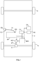
- la
figure 1 illustre schématiquement et fonctionnellement un exemple de réalisation d'un véhicule selon l'invention comprenant une première déclinaison de chaîne de transmission électrique, et - la
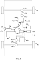
figure 2 illustre schématiquement et fonctionnellement le véhicule de lafigure 1 avec une seconde déclinaison de chaîne de transmission électrique. - L'invention a notamment pour but de proposer un véhicule V comprenant une chaîne de transmission comportant selon la déclinaison soit une première machine motrice MM1 électrique et participant à l'entraînement d'un premier train T1, soit des première MM1 et seconde MM2 machines motrices électriques et participant à l'entraînement respectivement de premier T1 et second T2 trains, mais une même batterie rechargeable BR.
- Dans ce qui suit, on considère, à titre d'exemple non limitatif, que le véhicule V est de type automobile. Il s'agit par exemple d'une voiture. Mais l'invention n'est pas limitée à ce type de véhicule. Elle concerne en effet tout type de véhicule comprenant une chaîne de transmission pouvant comporter une ou deux machines motrices électriques. Par conséquent, l'invention concerne au moins les véhicules terrestres.
- Il est rappelé que l'on entend ici par « machine motrice électrique » une machine (ou un moteur) électrique agencé(e) de manière à fournir ou récupérer du couple pour déplacer un véhicule, soit seul(e) soit en complément d'au moins une éventuelle autre machine motrice électrique ou thermique (comme par exemple un moteur thermique (réacteur, turboréacteur ou moteur chimique)).
- On a schématiquement représenté sur les
figures 1 et2 un même exemple de véhicule V mais avec deux déclinaisons différentes de la chaîne de transmission. Dans ces deux déclinaisons, la chaîne de transmission comprend au moins une première machine motrice MM1 électrique et participant à l'entraînement d'un premier train T1, une batterie rechargeable BR et un chargeur CB. - Dans les deux déclinaisons illustrées non limitativement sur les
figures 1 et2 , la chaîne de transmission est de type tout électrique. Mais l'invention n'est pas limitée à ce type de chaîne de transmission. En effet, la chaîne de transmission pourrait être de type hybride en comportant en complément une machine motrice thermique associée à son second train T2. - La chaîne de transmission comprend ici, en complément de la première machine motrice MM1, de la batterie rechargeable BR et du chargeur CB, des premiers moyens de couplage MC1 et un premier arbre de transmission AT1. Le contrôle d'au moins la première machine motrice MM1 et des premiers moyens de couplage MC1 est assuré par un calculateur de supervision CS.
- La batterie rechargeable BR est agencée pour stocker de l'énergie électrique, par exemple en basse tension (typiquement 300 V). Elle peut notamment être rechangée via le chargeur CB, comme on le verra plus loin.
- Le chargeur CB est destiné à être raccordé à une source d'alimentation en courant externe, comme par exemple une borne de recharge ou une prise de courant du secteur, vi un cordon de charge dédié.
- Les premiers moyens de couplage MC1 sont ici chargés de coupler/ découpler la première machine motrice MM1 au/du premier arbre de transmission AT1, sur ordre du calculateur de supervision CS, afin de communiquer du couple qu'elle produit et qui est défini par une consigne (de couple ou de régime), grâce à l'énergie électrique stockée dans la batterie rechargeable BR, au premier arbre de transmission AT1. Ce dernier (AT1) est couplé au premier train T1 (ici de roues).
- Par exemple, le premier train T1 est situé à l'arrière du véhicule V, et de préférence, et comme illustré, couplé au premier arbre de transmission AT1 via un premier différentiel (ici arrière) D1. Mais dans une variante ce premier train T1 pourrait être situé à l'avant du véhicule V.
- Les premiers moyens de couplage MC1 peuvent, par exemple, être un mécanisme à crabots ou un embrayage ou un convertisseur de couple hydraulique ou encore un frein. Ils peuvent prendre au moins deux états de couplage : un premier (couplé) dans lequel ils assurent le couplage de la première machine motrice MM1 au premier arbre de transmission AT1 et un second (découplé) dans lequel ils découplent la première machine motrice MM1 du premier arbre de transmission AT1. On notera qu'ils peuvent également prendre un état intermédiaire (par exemple pour un glissement d'embrayage).
- Dans la seconde déclinaison illustrée sur la
figure 2 , la chaîne de transmission comprend, en complément de celle illustrée sur lafigure 1 , une seconde machine motrice MM2, des seconds moyens de couplage MC2 et un second arbre de transmission AT2. - La seconde machine motrice MM2 est de type électrique et participe à l'entraînement du second train T2.
- Les seconds moyens de couplage MC2 sont ici chargés de coupler/ découpler la seconde machine motrice MM2 au/du second arbre de transmission AT2, sur ordre du calculateur de supervision CS, afin de communiquer du couple qu'elle produit et qui est défini par une consigne (de couple ou de régime), grâce à l'énergie électrique stockée dans la batterie rechargeable BR, au second arbre de transmission AT2. Ce dernier (AT2) est couplé au second train T2 (ici de roues).
- Par exemple, le second train T2 est situé à l'avant du véhicule V, et couplé au second arbre de transmission AT2, de préférence, et comme illustré, via un second différentiel (ici avant) D2. Mais dans la variante précitée ce second train T2 pourrait être situé à l'arrière du véhicule V.
- Les seconds moyens de couplage MC2 peuvent, par exemple, être un mécanisme à crabots ou un embrayage ou un convertisseur de couple hydraulique ou encore un frein. Ils peuvent prendre au moins deux états de couplage : un premier (couplé) dans lequel ils assurent le couplage de la seconde machine motrice MM2 au second arbre de transmission AT2 et un second (découplé) dans lequel ils découplent la seconde machine motrice MM2 du second arbre de transmission AT2. On notera qu'ils peuvent également prendre un état intermédiaire (par exemple pour un glissement d'embrayage).
- Les fonctionnements de la seconde machine motrice MM2 et des seconds moyens de couplage MC2 sont contrôlés par le calculateur de supervision CS.
- On notera également, comme illustré non limitativement sur les
figures 1 et2 , que la chaîne de transmission peut aussi comprendre une batterie de servitude BS très basse tension (par exemple 12 V, 24 V ou 48 V). Cette batterie de servitude BS peut, par exemple, alimenter un réseau de bord auquel sont connectés des équipements électriques du véhicule V. On notera que la batterie de servitude BS peut, comme illustré non limitativement sur lesfigures 1 et2 , être couplée à la batterie rechargeable BR via un convertisseur CV de type DC/DC, afin de pouvoir être rechargée. - Selon l'invention, en l'absence de la seconde machine motrice MM2 (déclinaison de la
figure 1 ), la batterie rechargeable BR est couplée directement au chargeur CB via un premier faisceau électrique F1, tandis qu'en présence de la seconde machine motrice MM2 (déclinaison de lafigure 2 ), la batterie rechargeable BR est couplée indirectement au chargeur CB via la seconde machine motrice MM2 et des premier F1 et second F2 faisceaux électriques. - En d'autres termes, dans la première déclinaison de la
figure 1 , on recharge la batterie rechargeable BR par un couplage direct au chargeur CB via un premier faisceau électrique F1, tandis que dans la seconde déclinaison de lafigure 2 , on recharge la batterie rechargeable BR par un couplage indirect au chargeur CB via le premier faisceau électrique F1, la seconde machine motrice MM2 et le second faisceau électrique F2. - Ainsi, on peut avantageusement utiliser la même batterie rechargeable BR pour les deux déclinaisons de la chaîne de transmission, ce qui facilite la gestion de stock et la logistique tant en usine que dans les services après-vente. De plus, on est certain qu'une fois que l'on a conçu la seconde déclinaison (ou architecture) la plus complexe (c'est-à-dire à deux machines motrices électriques MM1 et MM2), la première déclinaison (ou architecture) à une seule machine motrice électrique MM1 peut être déduite de la seconde déclinaison par un retrait de la seconde machine motrice électrique MM2 et des équipements associés (MC2, AT2 et D2) en conservant le même chargeur CB et la même batterie rechargeable BR, ce qui simplifie la phase de conception du véhicule V.
- Afin de permettre cette double déclinaison, la seconde machine motrice MM2 peut, comme illustré sur la
figure 2 , comprendre une première interface de couplage IC1 comprenant des première P11 et seconde P12 parties. La première partie P11 est couplée à la batterie rechargeable BR via le premier faisceau électrique F1 et la seconde partie P12 est couplée au chargeur CB via le second faisceau électrique F2. - Ainsi, lors d'une recharge, étant donné que la seconde machine motrice MM2 ne consomme pas de courant, le courant issu du chargeur CB remonte automatiquement vers la batterie rechargeable BR via le premier faisceau électrique F1. Par ailleurs, en dehors d'une recharge, lorsque la seconde machine motrice MM2 est utilisée, elle consomme du courant de la batterie rechargeable BR via le premier faisceau électrique F1.
- Dans une variante de réalisation non illustrée, la seconde partie P12 de la première interface de couplage IC1 pourrait être couplée à la première partie P11 de la première interface de couplage IC1, par exemple via des moyens de commutation chargés de contrôler la recharge par le chargeur CB.
- On notera que le chargeur CB peut, comme illustré sur les
figures 1 et2 , comprendre une seconde interface de couplage IC2 connectée au premier faisceau électrique F1 en l'absence de la seconde machine motrice MM2, et connectée au second faisceau électrique F2 en présence de la seconde machine motrice MM2. - Dans une variante de réalisation non illustrée, la seconde interface de couplage IC2 pourrait comprendre des première et seconde parties. Une première partie est connectée au premier faisceau électrique F1 en l'absence de la seconde machine motrice MM2, et une seconde partie P22 est connectée au second faisceau électrique F2 en présence de la seconde machine motrice MM2.
- De son côté, la batterie rechargeable BR comprend une troisième interface de couplage IC3 à laquelle est connecté le premier faisceau électrique F1 dans les deux déclinaisons.
- On notera également, comme évoqué précédemment que la chaîne de transmission peut également et éventuellement comprendre une troisième machine motrice thermique et participant à l'entraînement du second train T2. Dans ce cas, cette troisième machine motrice (par exemple un moteur thermique) peut comprendre un vilebrequin solidarisé fixement à un arbre moteur et destiné à fournir du couple pour le second train T2, via des troisièmes moyens de couplage et les seconds moyens de couplage MC2. Ces troisièmes moyens de couplage peuvent, par exemple, être agencés sous la forme d'un embrayage. Mais il pourrait également s'agir d'un convertisseur de couple ou d'un crabot ou encore d'un frein. On notera que lorsque les troisièmes moyens de couplage sont associés aux seconds moyens de couplage MC2, ces derniers sont de préférence agencés sous la forme de moyens de changement de rapport (comme par exemple une boîte de vitesses ou au moins un train épicycloïdal).
Claims (6)
- Véhicule (V) comprenant une chaîne de transmission comportant une première machine motrice (MM1) électrique et participant à l'entraînement d'un premier train (T1), au moins une batterie rechargeable (BR) alimentant en énergie électrique au moins ladite première machine motrice (MM1) et couplée à un chargeur (CB), ainsi qu'éventuellement une seconde machine motrice (MM2) électrique et participant à l'entraînement d'un second train (T2), caractérisé en ce qu'en l'absence de ladite seconde machine motrice (MM2) ladite batterie rechargeable (BR) est couplée directement audit chargeur (CB) via un premier faisceau électrique (F1), tandis qu'en présence de ladite seconde machine motrice (MM2) ladite batterie rechargeable (BR) est couplée indirectement audit chargeur (CB) via ladite seconde machine motrice (MM2) et le premier (F1) et un second (F2) faisceaux électriques.
- Véhicule selon la revendication 1, caractérisé en ce que ladite seconde machine motrice (MM2) comprend une première interface de couplage (IC1) comprenant une première partie (P11) couplée à ladite batterie rechargeable (BR) via ledit premier faisceau électrique (F1) et une seconde partie (P12) couplée audit chargeur (CB) via ledit second faisceau électrique (F2).
- Véhicule selon la revendication 1, caractérisé en ce que ladite seconde machine motrice (MM2) comprend une première interface de couplage (IC1) comprenant une première partie (P11) couplée à ladite batterie rechargeable (BR) via ledit premier faisceau électrique (F1) et une seconde partie (P12) couplée audit chargeur (CB) via ledit second faisceau électrique (F2) et à ladite première partie (P11) via des moyens de commutation chargés de contrôler la recharge par ledit chargeur (CB).
- Véhicule selon l'une des revendications 1 à 3, caractérisé en ce que ledit chargeur (CB) comprend une seconde interface de couplage (IC2) connectée audit premier faisceau électrique (F1) en l'absence de ladite seconde machine motrice (MM2), et connectée audit second faisceau électrique (F2) en présence de ladite seconde machine motrice (MM2).
- Véhicule selon l'une des revendications 1 à 4, caractérisé en ce que ladite chaîne de transmission comprend également une troisième machine motrice thermique et participant à l'entraînement dudit second train (T2).
- Véhicule selon l'une des revendications 1 à 5, caractérisé en ce qu'il est de type automobile.
Applications Claiming Priority (2)
| Application Number | Priority Date | Filing Date | Title |
|---|---|---|---|
| FR1754375A FR3066448B1 (fr) | 2017-05-18 | 2017-05-18 | Vehicule a machine motrice electrique optionnelle couplant une batterie non diversifiable a un chargeur |
| PCT/FR2018/051083 WO2018211195A1 (fr) | 2017-05-18 | 2018-05-02 | Véhicule à machine motrice électrique optionnelle couplant une batterie non diversifiable à un chargeur |
Publications (2)
| Publication Number | Publication Date |
|---|---|
| EP3625077A1 EP3625077A1 (fr) | 2020-03-25 |
| EP3625077B1 true EP3625077B1 (fr) | 2021-04-14 |
Family
ID=59325490
Family Applications (1)
| Application Number | Title | Priority Date | Filing Date |
|---|---|---|---|
| EP18735351.1A Active EP3625077B1 (fr) | 2017-05-18 | 2018-05-02 | Véhicule à machine motrice électrique optionnelle couplant une batterie non diversifiable à un chargeur |
Country Status (5)
| Country | Link |
|---|---|
| EP (1) | EP3625077B1 (fr) |
| CN (1) | CN110678348B (fr) |
| FR (1) | FR3066448B1 (fr) |
| MA (1) | MA49146B1 (fr) |
| WO (1) | WO2018211195A1 (fr) |
Family Cites Families (7)
| Publication number | Priority date | Publication date | Assignee | Title |
|---|---|---|---|---|
| US5099186A (en) * | 1990-12-31 | 1992-03-24 | General Motors Inc. | Integrated motor drive and recharge system |
| CN1055895C (zh) * | 1995-05-19 | 2000-08-30 | 丰田自动车株式会社 | 动力传送装置及采用该装置的四轮驱动车辆以及动力传送方法及四轮驱动方法 |
| JP2010193548A (ja) * | 2009-02-16 | 2010-09-02 | Denso Corp | 車両走行制御装置 |
| US7794280B1 (en) * | 2009-03-04 | 2010-09-14 | Gm Global Technology Operations, Inc. | Charge receptacle for plug-in electric vehicle |
| KR101189237B1 (ko) * | 2010-07-09 | 2012-10-09 | 현대자동차주식회사 | 하이브리드 자동차의 충전장치 및 방법 |
| JP6094060B2 (ja) * | 2012-05-31 | 2017-03-15 | 三菱自動車工業株式会社 | バッテリケース |
| JP2015061414A (ja) * | 2013-09-19 | 2015-03-30 | トヨタ自動車株式会社 | 電動車両 |
-
2017
- 2017-05-18 FR FR1754375A patent/FR3066448B1/fr not_active Expired - Fee Related
-
2018
- 2018-05-02 WO PCT/FR2018/051083 patent/WO2018211195A1/fr not_active Ceased
- 2018-05-02 MA MA49146A patent/MA49146B1/fr unknown
- 2018-05-02 CN CN201880032985.2A patent/CN110678348B/zh active Active
- 2018-05-02 EP EP18735351.1A patent/EP3625077B1/fr active Active
Non-Patent Citations (1)
| Title |
|---|
| None * |
Also Published As
| Publication number | Publication date |
|---|---|
| CN110678348B (zh) | 2023-02-24 |
| FR3066448B1 (fr) | 2019-06-21 |
| FR3066448A1 (fr) | 2018-11-23 |
| WO2018211195A1 (fr) | 2018-11-22 |
| EP3625077A1 (fr) | 2020-03-25 |
| CN110678348A (zh) | 2020-01-10 |
| MA49146B1 (fr) | 2021-07-29 |
| MA49146A (fr) | 2020-03-25 |
Similar Documents
| Publication | Publication Date | Title |
|---|---|---|
| US9370992B2 (en) | Powertrain for a vehicle | |
| US9108633B1 (en) | Hybrid powertrain and method of controlling same | |
| CN101809325B (zh) | 具有高效纯电动模式的混合动力系 | |
| US9440641B2 (en) | Control device for hybrid vehicle | |
| EP2726757B1 (fr) | Architecture électrique de véhicule hybride, véhicule hybride et procédé de commande | |
| CN111448094A (zh) | 安装在变速器上的具有双模式负载和发动机关闭动载功率的充电系统 | |
| US9682671B2 (en) | Vehicle system with battery boost and bypass control | |
| CN102742117A (zh) | 用于优化混合动力车辆电池再充电的方法 | |
| US9656541B2 (en) | Self-contained electric axle for all-wheel drive | |
| CN105658464B (zh) | 用于机动车辆的动力系统以及运行方法 | |
| US10781731B2 (en) | Method and assembly for heating an engine fluid | |
| EP3625077B1 (fr) | Véhicule à machine motrice électrique optionnelle couplant une batterie non diversifiable à un chargeur | |
| EP3589510B1 (fr) | Dispositif de contrôle des couplages/découplages d'une machine motrice d'un véhicule lors d'un changement de rapport | |
| EP3180220A1 (fr) | Procédé et dispositif de contrôle des modes de fonctionnement d'une chaîne de transmission hybride d'un véhicule, en fonction de lois d'évolution | |
| EP3638529B1 (fr) | Contrôle de la recharge à basse vitesse d'un stockeur d'un véhicule hybride à machine motrice non-thermique liée mécaniquement à un train | |
| FR3064575B1 (fr) | Dispositif de controle des couplages/decouplages d'une machine motrice non-thermique d'un vehicule en fonction d'un parametre d'etat de moyens de stockage associes | |
| FR3070347A1 (fr) | Controle d’instants de declenchement d’une marche rampante par des moteur thermique et machine motrice non-thermique d’un vehicule hybride | |
| Gupta et al. | Development of a parallel hybrid electric vehicle | |
| GB2454888A (en) | Hybrid vehicle motor control matched to generation capability | |
| FR3078204A1 (fr) | Gestion de l’energie electrique dans un vehicule automobile hybride | |
| FR3070555A1 (fr) | Reseau d’alimentation electrique a trois tensions pour un vehicule a machine motrice electrique | |
| EP3678910B1 (fr) | Procédé de contrôle de fourniture d'un couple complémentaire par une machine motrice non-thermique d'un véhicule hybride en fonction du potentiel d'accélération | |
| FR3067665A1 (fr) | Architecture de traction munie d'un dispositif d'accouplement a deux rapports entre une machine electrique et un train arriere de vehicule automobile | |
| FR3147218A1 (fr) | Procede de pilotage d’une transmission dct en recuperation d’energie | |
| FR3070344A1 (fr) | Dispositif et procede de controle de l’intensite de deceleration d’un vehicule hybride induite par une machine non-thermique |
Legal Events
| Date | Code | Title | Description |
|---|---|---|---|
| STAA | Information on the status of an ep patent application or granted ep patent |
Free format text: STATUS: UNKNOWN |
|
| STAA | Information on the status of an ep patent application or granted ep patent |
Free format text: STATUS: THE INTERNATIONAL PUBLICATION HAS BEEN MADE |
|
| PUAI | Public reference made under article 153(3) epc to a published international application that has entered the european phase |
Free format text: ORIGINAL CODE: 0009012 |
|
| STAA | Information on the status of an ep patent application or granted ep patent |
Free format text: STATUS: REQUEST FOR EXAMINATION WAS MADE |
|
| 17P | Request for examination filed |
Effective date: 20191017 |
|
| AK | Designated contracting states |
Kind code of ref document: A1 Designated state(s): AL AT BE BG CH CY CZ DE DK EE ES FI FR GB GR HR HU IE IS IT LI LT LU LV MC MK MT NL NO PL PT RO RS SE SI SK SM TR |
|
| AX | Request for extension of the european patent |
Extension state: BA ME |
|
| DAX | Request for extension of the european patent (deleted) | ||
| RAV | Requested validation state of the european patent: fee paid |
Extension state: MA Effective date: 20191017 |
|
| RAP1 | Party data changed (applicant data changed or rights of an application transferred) |
Owner name: PSA AUTOMOBILES SA |
|
| REG | Reference to a national code |
Ref country code: DE Ref legal event code: R079 Ref document number: 602018015584 Country of ref document: DE Free format text: PREVIOUS MAIN CLASS: B60L0011180000 Ipc: B60L0050150000 |
|
| GRAP | Despatch of communication of intention to grant a patent |
Free format text: ORIGINAL CODE: EPIDOSNIGR1 |
|
| STAA | Information on the status of an ep patent application or granted ep patent |
Free format text: STATUS: GRANT OF PATENT IS INTENDED |
|
| RIC1 | Information provided on ipc code assigned before grant |
Ipc: B60K 17/354 20060101ALI20201119BHEP Ipc: B60K 1/02 20060101ALI20201119BHEP Ipc: B60L 15/00 20060101ALI20201119BHEP Ipc: B60L 53/14 20190101ALI20201119BHEP Ipc: B60L 53/22 20190101ALI20201119BHEP Ipc: B60L 50/15 20190101AFI20201119BHEP Ipc: B60L 50/60 20190101ALI20201119BHEP |
|
| INTG | Intention to grant announced |
Effective date: 20201207 |
|
| GRAS | Grant fee paid |
Free format text: ORIGINAL CODE: EPIDOSNIGR3 |
|
| GRAA | (expected) grant |
Free format text: ORIGINAL CODE: 0009210 |
|
| STAA | Information on the status of an ep patent application or granted ep patent |
Free format text: STATUS: THE PATENT HAS BEEN GRANTED |
|
| AK | Designated contracting states |
Kind code of ref document: B1 Designated state(s): AL AT BE BG CH CY CZ DE DK EE ES FI FR GB GR HR HU IE IS IT LI LT LU LV MC MK MT NL NO PL PT RO RS SE SI SK SM TR |
|
| REG | Reference to a national code |
Ref country code: GB Ref legal event code: FG4D Free format text: NOT ENGLISH |
|
| REG | Reference to a national code |
Ref country code: CH Ref legal event code: EP |
|
| REG | Reference to a national code |
Ref country code: DE Ref legal event code: R084 Ref document number: 602018015584 Country of ref document: DE |
|
| REG | Reference to a national code |
Ref country code: DE Ref legal event code: R096 Ref document number: 602018015584 Country of ref document: DE |
|
| REG | Reference to a national code |
Ref country code: IE Ref legal event code: FG4D Free format text: LANGUAGE OF EP DOCUMENT: FRENCH |
|
| REG | Reference to a national code |
Ref country code: AT Ref legal event code: REF Ref document number: 1382052 Country of ref document: AT Kind code of ref document: T Effective date: 20210515 |
|
| REG | Reference to a national code |
Ref country code: GB Ref legal event code: 746 Effective date: 20210614 |
|
| REG | Reference to a national code |
Ref country code: MA Ref legal event code: VAGR Ref document number: 49146 Country of ref document: MA Kind code of ref document: B1 |
|
| REG | Reference to a national code |
Ref country code: LT Ref legal event code: MG9D |
|
| REG | Reference to a national code |
Ref country code: AT Ref legal event code: MK05 Ref document number: 1382052 Country of ref document: AT Kind code of ref document: T Effective date: 20210414 |
|
| REG | Reference to a national code |
Ref country code: NL Ref legal event code: MP Effective date: 20210414 |
|
| PG25 | Lapsed in a contracting state [announced via postgrant information from national office to epo] |
Ref country code: HR Free format text: LAPSE BECAUSE OF FAILURE TO SUBMIT A TRANSLATION OF THE DESCRIPTION OR TO PAY THE FEE WITHIN THE PRESCRIBED TIME-LIMIT Effective date: 20210414 Ref country code: LT Free format text: LAPSE BECAUSE OF FAILURE TO SUBMIT A TRANSLATION OF THE DESCRIPTION OR TO PAY THE FEE WITHIN THE PRESCRIBED TIME-LIMIT Effective date: 20210414 Ref country code: FI Free format text: LAPSE BECAUSE OF FAILURE TO SUBMIT A TRANSLATION OF THE DESCRIPTION OR TO PAY THE FEE WITHIN THE PRESCRIBED TIME-LIMIT Effective date: 20210414 Ref country code: AT Free format text: LAPSE BECAUSE OF FAILURE TO SUBMIT A TRANSLATION OF THE DESCRIPTION OR TO PAY THE FEE WITHIN THE PRESCRIBED TIME-LIMIT Effective date: 20210414 Ref country code: BG Free format text: LAPSE BECAUSE OF FAILURE TO SUBMIT A TRANSLATION OF THE DESCRIPTION OR TO PAY THE FEE WITHIN THE PRESCRIBED TIME-LIMIT Effective date: 20210714 Ref country code: NL Free format text: LAPSE BECAUSE OF FAILURE TO SUBMIT A TRANSLATION OF THE DESCRIPTION OR TO PAY THE FEE WITHIN THE PRESCRIBED TIME-LIMIT Effective date: 20210414 |
|
| PG25 | Lapsed in a contracting state [announced via postgrant information from national office to epo] |
Ref country code: IS Free format text: LAPSE BECAUSE OF FAILURE TO SUBMIT A TRANSLATION OF THE DESCRIPTION OR TO PAY THE FEE WITHIN THE PRESCRIBED TIME-LIMIT Effective date: 20210814 Ref country code: GR Free format text: LAPSE BECAUSE OF FAILURE TO SUBMIT A TRANSLATION OF THE DESCRIPTION OR TO PAY THE FEE WITHIN THE PRESCRIBED TIME-LIMIT Effective date: 20210715 Ref country code: RS Free format text: LAPSE BECAUSE OF FAILURE TO SUBMIT A TRANSLATION OF THE DESCRIPTION OR TO PAY THE FEE WITHIN THE PRESCRIBED TIME-LIMIT Effective date: 20210414 Ref country code: SE Free format text: LAPSE BECAUSE OF FAILURE TO SUBMIT A TRANSLATION OF THE DESCRIPTION OR TO PAY THE FEE WITHIN THE PRESCRIBED TIME-LIMIT Effective date: 20210414 Ref country code: PT Free format text: LAPSE BECAUSE OF FAILURE TO SUBMIT A TRANSLATION OF THE DESCRIPTION OR TO PAY THE FEE WITHIN THE PRESCRIBED TIME-LIMIT Effective date: 20210816 Ref country code: LV Free format text: LAPSE BECAUSE OF FAILURE TO SUBMIT A TRANSLATION OF THE DESCRIPTION OR TO PAY THE FEE WITHIN THE PRESCRIBED TIME-LIMIT Effective date: 20210414 Ref country code: NO Free format text: LAPSE BECAUSE OF FAILURE TO SUBMIT A TRANSLATION OF THE DESCRIPTION OR TO PAY THE FEE WITHIN THE PRESCRIBED TIME-LIMIT Effective date: 20210714 Ref country code: PL Free format text: LAPSE BECAUSE OF FAILURE TO SUBMIT A TRANSLATION OF THE DESCRIPTION OR TO PAY THE FEE WITHIN THE PRESCRIBED TIME-LIMIT Effective date: 20210414 |
|
| REG | Reference to a national code |
Ref country code: CH Ref legal event code: PL |
|
| REG | Reference to a national code |
Ref country code: DE Ref legal event code: R097 Ref document number: 602018015584 Country of ref document: DE |
|
| PG25 | Lapsed in a contracting state [announced via postgrant information from national office to epo] |
Ref country code: ES Free format text: LAPSE BECAUSE OF FAILURE TO SUBMIT A TRANSLATION OF THE DESCRIPTION OR TO PAY THE FEE WITHIN THE PRESCRIBED TIME-LIMIT Effective date: 20210414 Ref country code: EE Free format text: LAPSE BECAUSE OF FAILURE TO SUBMIT A TRANSLATION OF THE DESCRIPTION OR TO PAY THE FEE WITHIN THE PRESCRIBED TIME-LIMIT Effective date: 20210414 Ref country code: SK Free format text: LAPSE BECAUSE OF FAILURE TO SUBMIT A TRANSLATION OF THE DESCRIPTION OR TO PAY THE FEE WITHIN THE PRESCRIBED TIME-LIMIT Effective date: 20210414 Ref country code: RO Free format text: LAPSE BECAUSE OF FAILURE TO SUBMIT A TRANSLATION OF THE DESCRIPTION OR TO PAY THE FEE WITHIN THE PRESCRIBED TIME-LIMIT Effective date: 20210414 Ref country code: SM Free format text: LAPSE BECAUSE OF FAILURE TO SUBMIT A TRANSLATION OF THE DESCRIPTION OR TO PAY THE FEE WITHIN THE PRESCRIBED TIME-LIMIT Effective date: 20210414 Ref country code: CZ Free format text: LAPSE BECAUSE OF FAILURE TO SUBMIT A TRANSLATION OF THE DESCRIPTION OR TO PAY THE FEE WITHIN THE PRESCRIBED TIME-LIMIT Effective date: 20210414 Ref country code: DK Free format text: LAPSE BECAUSE OF FAILURE TO SUBMIT A TRANSLATION OF THE DESCRIPTION OR TO PAY THE FEE WITHIN THE PRESCRIBED TIME-LIMIT Effective date: 20210414 Ref country code: CH Free format text: LAPSE BECAUSE OF NON-PAYMENT OF DUE FEES Effective date: 20210531 Ref country code: LI Free format text: LAPSE BECAUSE OF NON-PAYMENT OF DUE FEES Effective date: 20210531 Ref country code: MC Free format text: LAPSE BECAUSE OF FAILURE TO SUBMIT A TRANSLATION OF THE DESCRIPTION OR TO PAY THE FEE WITHIN THE PRESCRIBED TIME-LIMIT Effective date: 20210414 Ref country code: LU Free format text: LAPSE BECAUSE OF NON-PAYMENT OF DUE FEES Effective date: 20210502 |
|
| REG | Reference to a national code |
Ref country code: BE Ref legal event code: MM Effective date: 20210531 |
|
| PLBE | No opposition filed within time limit |
Free format text: ORIGINAL CODE: 0009261 |
|
| STAA | Information on the status of an ep patent application or granted ep patent |
Free format text: STATUS: NO OPPOSITION FILED WITHIN TIME LIMIT |
|
| 26N | No opposition filed |
Effective date: 20220117 |
|
| PG25 | Lapsed in a contracting state [announced via postgrant information from national office to epo] |
Ref country code: IE Free format text: LAPSE BECAUSE OF NON-PAYMENT OF DUE FEES Effective date: 20210502 |
|
| PG25 | Lapsed in a contracting state [announced via postgrant information from national office to epo] |
Ref country code: IS Free format text: LAPSE BECAUSE OF FAILURE TO SUBMIT A TRANSLATION OF THE DESCRIPTION OR TO PAY THE FEE WITHIN THE PRESCRIBED TIME-LIMIT Effective date: 20210814 Ref country code: AL Free format text: LAPSE BECAUSE OF FAILURE TO SUBMIT A TRANSLATION OF THE DESCRIPTION OR TO PAY THE FEE WITHIN THE PRESCRIBED TIME-LIMIT Effective date: 20210414 |
|
| PG25 | Lapsed in a contracting state [announced via postgrant information from national office to epo] |
Ref country code: IT Free format text: LAPSE BECAUSE OF FAILURE TO SUBMIT A TRANSLATION OF THE DESCRIPTION OR TO PAY THE FEE WITHIN THE PRESCRIBED TIME-LIMIT Effective date: 20210414 Ref country code: BE Free format text: LAPSE BECAUSE OF NON-PAYMENT OF DUE FEES Effective date: 20210531 |
|
| PG25 | Lapsed in a contracting state [announced via postgrant information from national office to epo] |
Ref country code: CY Free format text: LAPSE BECAUSE OF FAILURE TO SUBMIT A TRANSLATION OF THE DESCRIPTION OR TO PAY THE FEE WITHIN THE PRESCRIBED TIME-LIMIT Effective date: 20210414 |
|
| PG25 | Lapsed in a contracting state [announced via postgrant information from national office to epo] |
Ref country code: HU Free format text: LAPSE BECAUSE OF FAILURE TO SUBMIT A TRANSLATION OF THE DESCRIPTION OR TO PAY THE FEE WITHIN THE PRESCRIBED TIME-LIMIT; INVALID AB INITIO Effective date: 20180502 |
|
| REG | Reference to a national code |
Ref country code: DE Ref legal event code: R081 Ref document number: 602018015584 Country of ref document: DE Owner name: STELLANTIS AUTO SAS, FR Free format text: FORMER OWNER: PSA AUTOMOBILES SA, POISSY, FR |
|
| PG25 | Lapsed in a contracting state [announced via postgrant information from national office to epo] |
Ref country code: MK Free format text: LAPSE BECAUSE OF FAILURE TO SUBMIT A TRANSLATION OF THE DESCRIPTION OR TO PAY THE FEE WITHIN THE PRESCRIBED TIME-LIMIT Effective date: 20210414 |
|
| VS25 | Lapsed in a validation state [announced via postgrant information from nat. office to epo] |
Ref country code: MA Free format text: LAPSE BECAUSE OF NON-PAYMENT OF DUE FEES Effective date: 20210503 |
|
| PG25 | Lapsed in a contracting state [announced via postgrant information from national office to epo] |
Ref country code: MT Free format text: LAPSE BECAUSE OF FAILURE TO SUBMIT A TRANSLATION OF THE DESCRIPTION OR TO PAY THE FEE WITHIN THE PRESCRIBED TIME-LIMIT Effective date: 20210414 |
|
| PGFP | Annual fee paid to national office [announced via postgrant information from national office to epo] |
Ref country code: DE Payment date: 20250423 Year of fee payment: 8 |
|
| PGFP | Annual fee paid to national office [announced via postgrant information from national office to epo] |
Ref country code: GB Payment date: 20250423 Year of fee payment: 8 |
|
| PGFP | Annual fee paid to national office [announced via postgrant information from national office to epo] |
Ref country code: FR Payment date: 20250423 Year of fee payment: 8 |
|
| PG25 | Lapsed in a contracting state [announced via postgrant information from national office to epo] |
Ref country code: TR Free format text: LAPSE BECAUSE OF FAILURE TO SUBMIT A TRANSLATION OF THE DESCRIPTION OR TO PAY THE FEE WITHIN THE PRESCRIBED TIME-LIMIT Effective date: 20210414 |