EP3624649B1 - Tableware article with collapsible base - Google Patents
Tableware article with collapsible base Download PDFInfo
- Publication number
- EP3624649B1 EP3624649B1 EP18803036.5A EP18803036A EP3624649B1 EP 3624649 B1 EP3624649 B1 EP 3624649B1 EP 18803036 A EP18803036 A EP 18803036A EP 3624649 B1 EP3624649 B1 EP 3624649B1
- Authority
- EP
- European Patent Office
- Prior art keywords
- bowl
- hinge
- foot
- tableware
- tableware article
- Prior art date
- Legal status (The legal status is an assumption and is not a legal conclusion. Google has not performed a legal analysis and makes no representation as to the accuracy of the status listed.)
- Active
Links
Images




Classifications
-
- A—HUMAN NECESSITIES
- A47—FURNITURE; DOMESTIC ARTICLES OR APPLIANCES; COFFEE MILLS; SPICE MILLS; SUCTION CLEANERS IN GENERAL
- A47G—HOUSEHOLD OR TABLE EQUIPMENT
- A47G19/00—Table service
- A47G19/02—Plates, dishes or the like
-
- A—HUMAN NECESSITIES
- A47—FURNITURE; DOMESTIC ARTICLES OR APPLIANCES; COFFEE MILLS; SPICE MILLS; SUCTION CLEANERS IN GENERAL
- A47G—HOUSEHOLD OR TABLE EQUIPMENT
- A47G23/00—Other table equipment
- A47G23/06—Serving trays
-
- A—HUMAN NECESSITIES
- A47—FURNITURE; DOMESTIC ARTICLES OR APPLIANCES; COFFEE MILLS; SPICE MILLS; SUCTION CLEANERS IN GENERAL
- A47J—KITCHEN EQUIPMENT; COFFEE MILLS; SPICE MILLS; APPARATUS FOR MAKING BEVERAGES
- A47J27/00—Cooking-vessels
- A47J27/10—Cooking-vessels with water-bath arrangements for domestic use
-
- A—HUMAN NECESSITIES
- A47—FURNITURE; DOMESTIC ARTICLES OR APPLIANCES; COFFEE MILLS; SPICE MILLS; SUCTION CLEANERS IN GENERAL
- A47J—KITCHEN EQUIPMENT; COFFEE MILLS; SPICE MILLS; APPARATUS FOR MAKING BEVERAGES
- A47J43/00—Implements for preparing or holding food, not provided for in other groups of this subclass
- A47J43/24—Devices for washing vegetables or the like
-
- B—PERFORMING OPERATIONS; TRANSPORTING
- B65—CONVEYING; PACKING; STORING; HANDLING THIN OR FILAMENTARY MATERIAL
- B65D—CONTAINERS FOR STORAGE OR TRANSPORT OF ARTICLES OR MATERIALS, e.g. BAGS, BARRELS, BOTTLES, BOXES, CANS, CARTONS, CRATES, DRUMS, JARS, TANKS, HOPPERS, FORWARDING CONTAINERS; ACCESSORIES, CLOSURES, OR FITTINGS THEREFOR; PACKAGING ELEMENTS; PACKAGES
- B65D1/00—Rigid or semi-rigid containers having bodies formed in one piece, e.g. by casting metallic material, by moulding plastics, by blowing vitreous material, by throwing ceramic material, by moulding pulped fibrous material or by deep-drawing operations performed on sheet material
- B65D1/22—Boxes or like containers with side walls of substantial depth for enclosing contents
- B65D1/24—Boxes or like containers with side walls of substantial depth for enclosing contents with moulded compartments or partitions
-
- B—PERFORMING OPERATIONS; TRANSPORTING
- B65—CONVEYING; PACKING; STORING; HANDLING THIN OR FILAMENTARY MATERIAL
- B65D—CONTAINERS FOR STORAGE OR TRANSPORT OF ARTICLES OR MATERIALS, e.g. BAGS, BARRELS, BOTTLES, BOXES, CANS, CARTONS, CRATES, DRUMS, JARS, TANKS, HOPPERS, FORWARDING CONTAINERS; ACCESSORIES, CLOSURES, OR FITTINGS THEREFOR; PACKAGING ELEMENTS; PACKAGES
- B65D21/00—Nestable, stackable or joinable containers; Containers of variable capacity
- B65D21/08—Containers of variable capacity
- B65D21/086—Collapsible or telescopic containers
-
- A—HUMAN NECESSITIES
- A47—FURNITURE; DOMESTIC ARTICLES OR APPLIANCES; COFFEE MILLS; SPICE MILLS; SUCTION CLEANERS IN GENERAL
- A47G—HOUSEHOLD OR TABLE EQUIPMENT
- A47G19/00—Table service
- A47G19/22—Drinking vessels or saucers used for table service
- A47G2019/2277—Drinking vessels or saucers used for table service collapsible
-
- B—PERFORMING OPERATIONS; TRANSPORTING
- B65—CONVEYING; PACKING; STORING; HANDLING THIN OR FILAMENTARY MATERIAL
- B65D—CONTAINERS FOR STORAGE OR TRANSPORT OF ARTICLES OR MATERIALS, e.g. BAGS, BARRELS, BOTTLES, BOXES, CANS, CARTONS, CRATES, DRUMS, JARS, TANKS, HOPPERS, FORWARDING CONTAINERS; ACCESSORIES, CLOSURES, OR FITTINGS THEREFOR; PACKAGING ELEMENTS; PACKAGES
- B65D25/00—Details of other kinds or types of rigid or semi-rigid containers
- B65D25/28—Handles
- B65D25/2882—Integral handles
- B65D25/2888—Integral handles provided near to or at the upper edge or rim
-
- B—PERFORMING OPERATIONS; TRANSPORTING
- B65—CONVEYING; PACKING; STORING; HANDLING THIN OR FILAMENTARY MATERIAL
- B65D—CONTAINERS FOR STORAGE OR TRANSPORT OF ARTICLES OR MATERIALS, e.g. BAGS, BARRELS, BOTTLES, BOXES, CANS, CARTONS, CRATES, DRUMS, JARS, TANKS, HOPPERS, FORWARDING CONTAINERS; ACCESSORIES, CLOSURES, OR FITTINGS THEREFOR; PACKAGING ELEMENTS; PACKAGES
- B65D25/00—Details of other kinds or types of rigid or semi-rigid containers
- B65D25/28—Handles
- B65D25/2882—Integral handles
- B65D25/2897—Integral handles formed in the wall(s), e.g. roughenings, cavities or projections
Definitions
- the present application relates to tableware having an extendable and retractable base.
- a tableware article such as a plate or a bowl
- a bath of hot water in order to heat the contents of the tableware article.
- many plates and bowls do not have a base with sufficient height to allow them to be stably set in even shallow water.
- setting a plate or a bowl in water often traps air beneath it, further destabilizing the plate or bowl. Accordingly, there is a need for improvements to tableware.
- WO 2008/ 103183 A2 discloses an article of tableware according to the preamble of claim 1.
- CN 201806 387U discloses a foldable bowl comprising a bowl body integrally molded by silica gel material; the bowl body is divided into a plurality of sections connected by foldable grooves in the axial direction, the foldable grooves are V-shaped and the sections can be folded and unfolded by utilizing the foldable grooves. When the foldable bowl is used, the foldable bowl can be compressed from the top to the bottom, and is very thin on the side surface after folding.
- the pollution to the inner walls of the bowls is avoided when a plurality of bowls are stacked by adopting the conventional manor that the outer wall of an upper bowl is embedded into the inner wall of a lower bowl. Furthermore by adopting the foldable bowl, more space is saved during the storage and transportation, and packaging is easier.
- the present invention provides an article of tableware according to claim 1 and a method according to claim 10.
- the dependent claims relate to respective special embodiments thereof.
- a representative embodiment includes a container portion supported on a base portion that is collapsible such that a foot portion of the base portion is movable between an extended position and a retracted position.
- a foot portion of the base portion is movable between an extended position and a retracted position.
- the distance or height of the container portion above a surface on which the tableware article is set can be adjusted.
- the tableware article can be placed, for example, in a shallow bath of hot water such that the container portion is supported above the water bath in order to heat the contents of the container portion.
- This method of heating the contents of the container portion can be desirable when heating, for example, food for infants or young children.
- the tableware article can then be removed from the water bath, and the base portion can be collapsed such that the foot portion moves from the extended position to the retracted position for serving.
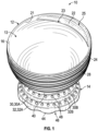
- FIG. 1 illustrates a representative embodiment of such a tableware article configured as a bowl 10.
- the bowl 10 includes a container portion configured as a bowl portion 12, and a base portion 14 coupled to the bowl portion 12 and configured to support the bowl portion above the base portion.
- the bowl portion 12 includes a well 13 defined by a curved wall 24.
- a rim 16 of the bowl portion 12 can be sloped such that the rim 16 has an upper rim portion 18 and a lower rim portion 20, with the upper rim portion being higher than the lower rim portion when the bowl is supported on a level surface.
- the bowl portion 12 includes also a handle portion 22.
- the handle portion 22 extends radially inwardly from the interior surface 21 of the upper rim portion 18 toward the center of the bowl portion 12.
- a radially inward edge 23 and a radially outward edge 25 of the handle portion 22 can be curved, such that the handle portion forms a crescent-shaped member.
- the handle portion 22 can have a variety of different shapes.
- the inward edge 23 of the handle portion 22 can be straight, while the outward edge 25 is curved to match the curvature of the bowl portion 12.
- the handle portion 22 can also extend along any suitable proportion of the circumference of the bowl portion 12, as desired.
- a thickness of the wall 24 vary about the circumference of the bowl portion 12.
- the wall 24 has first thickness t1 along the portion of the circumference of the bowl adjacent the upper rim portion 18 and/or the handle portion 22.
- the thickness of the wall 24 decreases along the circumference of the bowl such that a portion of the wall diametrically opposite the handle portion 22 has second thickness t2 that is less than the first thickness t1.
- the thickness t 1 can be about 4.5 mm
- the thickness t 2 can be about 2.8 mm.
- an exterior surface 26 of the bowl portion 12 can be textured to, for example, facilitate gripping the bowl portion without slipping.
- the exterior surface 26 can include a plurality of circumferentially-extending ribs or ridges 28 spaced apart along the height of the bowl portion 12.
- the exterior surface 26 can include any of various other textures or surface treatments, such as bumps, protrusions, etc.
- the exterior surface 26 need not include any texturing or surface treatment, and can be smooth, as shown in FIG. 12 .
- the surface 26 may also include graphics, patterns, etc., as desired.
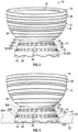
- the base portion 14 can be movable between an extended position ( FIGS. 1-5 ) and a retracted position ( FIGS. 8 and 9 ).
- the base portion 14 can comprise a tiered structure including a plurality of curved (e.g., circular) first extension portions configured as hinge portions 30, and curved (e.g., circular) second extension portions 32.
- the hinge portions 30 and the extension portions 32 can be arranged alternatingly one above the other.
- the base portion includes an extension portion 32A configured as a foot portion.
- a first hinge portion 30A can extend from the foot portion 32A at an angle to the foot portion (e.g., angled radially inward toward the bowl).
- the first hinge portion 30A and the foot portion 32A can be coupled to each other at a first hinge line 34 of the hinge portion 30A.
- An extension portion 32B can be coupled to the first hinge portion 30A at a second hinge line 36 of the hinge portion 30A.
- the extension portion 32B can extend vertically relative to the hinge portion 30A, as shown in FIGS. 2-5 .
- the extension portion 32B can also be angled inwardly, as desired.
- a second hinge portion 30B can extend from the extension portion 32B at an angle such that the second hinge portion is oriented radially inwardly toward the center of the bowl.
- the second hinge portion 30B can be coupled to the extension portion 32B at a first hinge line 38 of the hinge portion 30B.
- the second hinge portion 30B can be coupled to a coupling portion 40 of the bowl portion 12 at a second hinge line 42.
- the hinge portions 30A, 30B can be pivotable about their respective hinge lines.
- the first hinge portion 30A can be pivotable about the hinge line 34 and the hinge line 36
- the second hinge portion 30B can be pivotable about the hinge line 38 and the hinge line 42.
- the hinge lines 34, 36, 38, 42 can be configured as living hinges, wherein the material of the respective hinge lines is relatively thin and flexible such that pivoting motion of the various portions of the base portion 14 occurs about the hinge lines.
- the hinge lines 34, 36, 38, 42 may also comprise other types of hinges, as desired.
- the foot portion 32A can have a diameter Di
- the extension portion 32B can have a diameter D 2
- the coupling portion 42 can have a diameter D 3 .
- the diameter D 1 of the foot portion 32A can be larger than the diameter D 2 of the extension 32B, which can be larger than the diameter D 3 of the coupling portion 42.
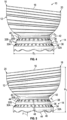
- FIGS. 5-8 illustrate motion of the base portion 14 and the foot portion 32A between the extended position and the retracted position.
- the second hinge portion 30B can be configured to pivot first when force is applied to the base portion 14.
- the second hinge portion 30B can pivot upwardly in the direction of arrow 44 about the hinge lines 38, 42, as shown in FIG. 5 .
- the hinge portion 30B has completed its pivot, the base portion can be in the position shown in FIG. 6 with the hinge portion 30B (out of view in FIG. 6 ) disposed concentrically and radially inwardly of the extension portion 32B.
- extension portion 32B can pivot downwardly about the hinge line 38 of the hinge portion 30B, and about the hinge line 36 of the hinge portion 30A, such that the extension portion 32B is inverted relative to the foot portion 32A.
- the portion of the base portion 14 on the left side of the figure is collapsed such that the corresponding portion of the foot portion 32A is in the retracted position, while the portion of the base portion (and, hence, of the foot portion 32A) on the right side of the figure remains in the extended position.
- the extension portion 32B is fully inverted, the base portion 14 is fully collapsed and the foot portion 32A is in the retracted position, as shown in FIG. 8 .
- the extension portion 32B (out of view in FIG. 8 ) can be nested concentrically between the coupling portion 42 and the foot portion 32A.
- the foot portion 32A and the hinge line 34 are also brought adjacent the bowl portion 12, as shown in FIGS. 8 and 9 .
- Motion of the foot portion 32A between the extended and retracted positions can raise and lower the bowl portion 12 relative to a surface on which the bowl 10 is situated.
- the bowl 10 when the base portion 14 is in the extended position, the bowl 10 can have a first height dimension H 1 measured from the lower edge of the foot portion 32A to the apex of the upper rim portion 18.
- the height H 1 can be about 8.7 cm.
- the height of the apex of the upper rim portion 18 can decrease to a second height H 2 .
- the bowl 10 can be supported on the hinge portion 30B when the foot portion 32A is in the retracted position.
- the second height dimension H 2 can be measured from the lowermost portion of the hinge portion 30B to the apex of the upper rim portion 18.
- the height H 2 can be about 6.5 cm.
- motion of the foot portion 32A between the extended and retracted positions can raise and lower the height of the bowl portion 12 by about 1.2 cm.
- the bowl 10 may also be configured to rest on the foot portion 32A when the foot portion is in the retracted position.
- the bowl 10 can be placed in a liquid bath 50 (e.g., a heated water bath) with the foot portion 32A in the extended position.
- a liquid bath 50 e.g., a heated water bath
- the foot portion 32A can have a scalloped edge defining a plurality of alternating extension portions 44 and recesses 46.
- the hinge portions 30A, 30B can also define a plurality of openings 48 extending around their circumferences. In this manner, water can flow into the interior volume defined by the base portion 14 (and air can flow out) through the recessed portions 46 and/or through the openings 48.
- the water bath 50 can have a depth less than a height of the base portion 14 when the foot portion 32A is in the extended position.
- the foot portion 32A can rest on a lower surface 52 of the water bath (e.g., on the bottom of a pot) and the bowl portion 12 can be supported above the water bath in order to heat the contents of the bowl.
- a user can grip the handle portion 22 and remove the bowl from the water bath.
- the base portion 14 can then be collapsed to move the foot portion 32A to the retracted position for serving.
- the bowl 10 is made from any of various flexible polymeric materials, such as silicone, plastic, etc., metals such as stainless steel, or porcelain, glass, or combinations thereof.
- the bowl portion 12 and the base portion 14 can be made from different materials.
- the bowl portion can be made from plastic, and the base portion can be made from silicone.
- the bowl portion 12 can include a member such as a metal plate (e.g., embedded in the lower portion of the bowl) to promote heating of the contents of the bowl and/or heat retention upon removal of the bowl from the water bath 50.
- the foot portion 32A need not have extensions or recesses.
- the lower edge of the foot portion 32A can be straight, or can have any other desired shape.
- the hinge portions 30A, 30B may have more or fewer openings 48 than in the illustrated embodiment, as desired.
- the base portion 14 can also comprise any desired number of hinge portions and extension portions depending upon, for example, the size of the tableware article, the desired height difference between the extended and retracted positions, etc.
- the bowl portion 12 is circular-shaped
- FIG. 13 illustrates another tableware article 100 having a container portion configured as a plate portion 102.
- the plate portion 102 can define a well 103, and can be coupled to a base portion 104.
- the base portion 104 can include a foot portion 106, and hinge portions 108, 110 separated by, and pivotable about, an extension portion 112, similar to the base portion 14 of FIG. 1 .
- the base portion 104 can be collapsible such that the foot portion 106 is movable between an extended position and a retracted position, as described above.
- the foot portion 106 can also include alternating extension portions 114 and recessed portions 116, and the hinge portions 108, 110 can define a plurality of openings 118 to facilitate placement of the base portion in a water bath.
- the plate portion 102 can also include a handle portion 120 extending radially inward toward the center of the well 103, similar to the handle portion 22 of FIG. 1 . In certain configurations, a diameter of the container portion 102 and/or a depth of the well 103 can be varied, as desired.
- FIG. 14 illustrates another embodiment of a tableware article 200 including a container portion 202 defining a plurality of compartments or wells 214 in the manner of, for example, a bento box.
- a base portion 204 is coupled to the container portion 202, and can include a foot portion 206, and hinge portions 208, 210.
- the hinge portions 208, 210 can be separated by, and pivotable about, an extension portion 212, similar to the base portion 14 of FIG. 1 .
- the base portion 204 can be collapsible such that the foot portion 206 is movable between an extended position and a retracted position, similar to the embodiments described above.
- the foot portion 206 can also include a plurality of extension portions 218 and recessed portions 220, and the hinge portions 208, 210 can define a plurality of openings 222.
- the wells 214 of the container portion 202 are separated by walls 216, and can be configured to receive, for example, different foods to be heated and/or served in the container portion.
- the container portion 202 defines three wells 214A, 214B, 214C, although the container portion may include more or fewer wells, as desired.
- collapsible base portion embodiments described herein can also be applicable to other types of tableware, including dishes, platters, trays, saucers, cups, bottles, and mugs, to name a few.
- FIGS. 15 and 16 illustrate additional embodiments of the bowl 10 of FIG. 1 .
- the singular forms “a,” “an,” and “the” include the plural forms unless the context clearly dictates otherwise. Additionally, the term “includes” means “comprises.” Further, the terms “coupled” and “associated” generally mean electrically, electromagnetically, and/or physically ( e.g. , mechanically or chemically) coupled or linked and does not exclude the presence of intermediate elements between the coupled or associated items absent specific contrary language.
- values, procedures, or apparatus may be referred to as "lowest,” “best,” “minimum,” or the like. It will be appreciated that such descriptions are intended to indicate that a selection among many alternatives can be made, and such selections need not be better, smaller, or otherwise preferable to other selections.
Landscapes
- Engineering & Computer Science (AREA)
- Mechanical Engineering (AREA)
- Food Science & Technology (AREA)
- Ceramic Engineering (AREA)
- Table Devices Or Equipment (AREA)
Description
- The present application relates to tableware having an extendable and retractable base.
- It can be desirable to place a tableware article, such as a plate or a bowl, in a bath of hot water in order to heat the contents of the tableware article. However, many plates and bowls do not have a base with sufficient height to allow them to be stably set in even shallow water. Moreover, setting a plate or a bowl in water often traps air beneath it, further destabilizing the plate or bowl. Accordingly, there is a need for improvements to tableware.
-
WO 2008/ 103183 A2 discloses an article of tableware according to the preamble of claim 1.CN 201806 387U discloses a foldable bowl comprising a bowl body integrally molded by silica gel material; the bowl body is divided into a plurality of sections connected by foldable grooves in the axial direction, the foldable grooves are V-shaped and the sections can be folded and unfolded by utilizing the foldable grooves. When the foldable bowl is used, the foldable bowl can be compressed from the top to the bottom, and is very thin on the side surface after folding. Therefore, the pollution to the inner walls of the bowls is avoided when a plurality of bowls are stacked by adopting the conventional manor that the outer wall of an upper bowl is embedded into the inner wall of a lower bowl. Furthermore by adopting the foldable bowl, more space is saved during the storage and transportation, and packaging is easier. - The present invention provides an article of tableware according to claim 1 and a method according to
claim 10.
The dependent claims relate to respective special embodiments thereof. - The foregoing and other objects, features, and advantages of the disclosed technology will become more apparent from the following detailed description, which proceeds with reference to the accompanying figures.
-
-
FIG. 1 is a perspective view of a representative embodiment of an article of tableware configured as a bowl. -
FIG. 2 is a front view of the bowl ofFIG. 1 . -
FIG. 3 is a rear view of the bowl ofFIG. 1 . -
FIG. 4 is a left side view of the bowl ofFIG. 1 . -
FIG. 5 is a right side view of the bowl ofFIG. 1 . -
FIG. 6 is a perspective view of the bowl ofFIG. 1 illustrating the base portion in a partially collapsed position with the second hinge portion pivoted upwardly toward the bowl portion. -
FIG. 7 is a perspective view of the bowl ofFIG. 1 illustrating a portion of the base portion collapsed such that a portion of the foot portion is in the retracted position and a portion of the foot portion is in the extended position. -
FIG. 8 is a front view of the bowl ofFIG. 1 illustrating the foot portion in the retracted position. -
FIG. 9 is a right side view of the bowl ofFIG. 1 illustrating the foot portion in the retracted position. -
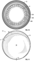
FIG. 10 is a bottom plan view of the bowl ofFIG. 1 with the foot portion shown in the extended position. -
FIG. 11 is a top plan view of the bowl ofFIG. 1 . -
FIG. 12 is a right side view of another embodiment of the bowl ofFIG. 1 . -
FIG. 13 is a perspective view of another embodiment of an article of tableware configured as a plate. -
FIG. 14 is a perspective view of another embodiment of an article of tableware including a container portion having a plurality of wells. -
FIG. 15 is a right side view of another embodiment of the bowl ofFIG. 1 . -
FIG. 16 is a perspective view of another embodiment of the bowl ofFIG. 1 . - Various embodiments of tableware articles including a movable or collapsible base are described herein. A representative embodiment includes a container portion supported on a base portion that is collapsible such that a foot portion of the base portion is movable between an extended position and a retracted position. By moving the foot portion between the extended position and the retracted position, the distance or height of the container portion above a surface on which the tableware article is set can be adjusted. Thus, when the foot portion is in the extended position, the tableware article can be placed, for example, in a shallow bath of hot water such that the container portion is supported above the water bath in order to heat the contents of the container portion. This method of heating the contents of the container portion can be desirable when heating, for example, food for infants or young children. The tableware article can then be removed from the water bath, and the base portion can be collapsed such that the foot portion moves from the extended position to the retracted position for serving.
-
FIG. 1 illustrates a representative embodiment of such a tableware article configured as abowl 10. Thebowl 10 includes a container portion configured as abowl portion 12, and abase portion 14 coupled to thebowl portion 12 and configured to support the bowl portion above the base portion. Thebowl portion 12 includes a well 13 defined by acurved wall 24. - With reference to
FIGS. 4 and 5 , arim 16 of thebowl portion 12 can be sloped such that therim 16 has anupper rim portion 18 and alower rim portion 20, with the upper rim portion being higher than the lower rim portion when the bowl is supported on a level surface. - Referring to
FIGS. 1 ,2 , and6 , thebowl portion 12 includes also ahandle portion 22. In the illustrated configuration, thehandle portion 22 extends radially inwardly from theinterior surface 21 of theupper rim portion 18 toward the center of thebowl portion 12. A radiallyinward edge 23 and a radiallyoutward edge 25 of thehandle portion 22 can be curved, such that the handle portion forms a crescent-shaped member. In other embodiments, thehandle portion 22 can have a variety of different shapes. For example, in some embodiments theinward edge 23 of thehandle portion 22 can be straight, while theoutward edge 25 is curved to match the curvature of thebowl portion 12. Thehandle portion 22 can also extend along any suitable proportion of the circumference of thebowl portion 12, as desired. - A thickness of the
wall 24 vary about the circumference of thebowl portion 12. With reference toFIG. 10 , thewall 24 has first thickness t1 along the portion of the circumference of the bowl adjacent theupper rim portion 18 and/or thehandle portion 22. The thickness of thewall 24 decreases along the circumference of the bowl such that a portion of the wall diametrically opposite thehandle portion 22 has second thickness t2 that is less than the first thickness t1. In this manner, where thebowl 10 is made from a flexible material, the increased thickness of thewall 24 at thehandle portion 22 can reduce deformation of the bowl when the bowl is grasped or lifted using thehandle portion 22, as described in greater detail below. In a representative embodiment, the thickness t1 can be about 4.5 mm, and the thickness t2 can be about 2.8 mm. - In the illustrated embodiment, an
exterior surface 26 of thebowl portion 12 can be textured to, for example, facilitate gripping the bowl portion without slipping. For example, with reference toFIGS. 1-9 , theexterior surface 26 can include a plurality of circumferentially-extending ribs orridges 28 spaced apart along the height of thebowl portion 12. Alternatively, theexterior surface 26 can include any of various other textures or surface treatments, such as bumps, protrusions, etc. In other embodiments, theexterior surface 26 need not include any texturing or surface treatment, and can be smooth, as shown inFIG. 12 . Thesurface 26 may also include graphics, patterns, etc., as desired. - As mentioned above, the
base portion 14 can be movable between an extended position (FIGS. 1-5 ) and a retracted position (FIGS. 8 and 9 ). In the illustrated embodiment, thebase portion 14 can comprise a tiered structure including a plurality of curved (e.g., circular) first extension portions configured as hinge portions 30, and curved (e.g., circular) second extension portions 32. For example, referring toFIGS. 1-5 , the hinge portions 30 and the extension portions 32 can be arranged alternatingly one above the other. In the illustrated embodiment, the base portion includes anextension portion 32A configured as a foot portion. Afirst hinge portion 30A can extend from thefoot portion 32A at an angle to the foot portion (e.g., angled radially inward toward the bowl). Thefirst hinge portion 30A and thefoot portion 32A can be coupled to each other at afirst hinge line 34 of thehinge portion 30A. Anextension portion 32B can be coupled to thefirst hinge portion 30A at asecond hinge line 36 of thehinge portion 30A. In some embodiments, theextension portion 32B can extend vertically relative to thehinge portion 30A, as shown inFIGS. 2-5 . However, in other embodiments, theextension portion 32B can also be angled inwardly, as desired. - A
second hinge portion 30B can extend from theextension portion 32B at an angle such that the second hinge portion is oriented radially inwardly toward the center of the bowl. Thesecond hinge portion 30B can be coupled to theextension portion 32B at afirst hinge line 38 of thehinge portion 30B. Thesecond hinge portion 30B can be coupled to acoupling portion 40 of thebowl portion 12 at asecond hinge line 42. In the illustrated embodiment, thehinge portions first hinge portion 30A can be pivotable about thehinge line 34 and thehinge line 36, and thesecond hinge portion 30B can be pivotable about thehinge line 38 and thehinge line 42. - In certain embodiments, the hinge lines 34, 36, 38, 42 can be configured as living hinges, wherein the material of the respective hinge lines is relatively thin and flexible such that pivoting motion of the various portions of the
base portion 14 occurs about the hinge lines. However, the hinge lines 34, 36, 38, 42 may also comprise other types of hinges, as desired. - With reference to
FIG. 4 , thefoot portion 32A can have a diameter Di, theextension portion 32B can have a diameter D2, and thecoupling portion 42 can have a diameter D3. In the illustrated embodiment, the diameter D1 of thefoot portion 32A can be larger than the diameter D2 of theextension 32B, which can be larger than the diameter D3 of thecoupling portion 42. -
FIGS. 5-8 illustrate motion of thebase portion 14 and thefoot portion 32A between the extended position and the retracted position. In some embodiments, thesecond hinge portion 30B can be configured to pivot first when force is applied to thebase portion 14. For example, when a force F is applied to thefoot portion 32A, thesecond hinge portion 30B can pivot upwardly in the direction ofarrow 44 about the hinge lines 38, 42, as shown inFIG. 5 . When thehinge portion 30B has completed its pivot, the base portion can be in the position shown inFIG. 6 with thehinge portion 30B (out of view inFIG. 6 ) disposed concentrically and radially inwardly of theextension portion 32B. - With reference to
FIG. 7 , further application of force can cause theextension portion 32B to pivot downwardly about thehinge line 38 of thehinge portion 30B, and about thehinge line 36 of thehinge portion 30A, such that theextension portion 32B is inverted relative to thefoot portion 32A. InFIG. 7 , the portion of thebase portion 14 on the left side of the figure is collapsed such that the corresponding portion of thefoot portion 32A is in the retracted position, while the portion of the base portion (and, hence, of thefoot portion 32A) on the right side of the figure remains in the extended position. When theextension portion 32B is fully inverted, thebase portion 14 is fully collapsed and thefoot portion 32A is in the retracted position, as shown inFIG. 8 . When thefoot portion 32A is in the retracted position, theextension portion 32B (out of view inFIG. 8 ) can be nested concentrically between thecoupling portion 42 and thefoot portion 32A. Thefoot portion 32A and thehinge line 34 are also brought adjacent thebowl portion 12, as shown inFIGS. 8 and 9 . - Motion of the
foot portion 32A between the extended and retracted positions can raise and lower thebowl portion 12 relative to a surface on which thebowl 10 is situated. For example, referring again toFIG. 5 , when thebase portion 14 is in the extended position, thebowl 10 can have a first height dimension H1 measured from the lower edge of thefoot portion 32A to the apex of theupper rim portion 18. In a representative embodiment, the height H1 can be about 8.7 cm. Referring toFIG. 9 , when thefoot portion 32A is in the retracted position, the height of the apex of theupper rim portion 18 can decrease to a second height H2. In the illustrated embodiment, thebowl 10 can be supported on thehinge portion 30B when thefoot portion 32A is in the retracted position. Thus, the second height dimension H2 can be measured from the lowermost portion of thehinge portion 30B to the apex of theupper rim portion 18. In a representative embodiment, the height H2 can be about 6.5 cm. Thus, in certain embodiments, motion of thefoot portion 32A between the extended and retracted positions can raise and lower the height of thebowl portion 12 by about 1.2 cm. In other embodiments, thebowl 10 may also be configured to rest on thefoot portion 32A when the foot portion is in the retracted position. - Referring again to
FIG. 3 , in use, thebowl 10 can be placed in a liquid bath 50 (e.g., a heated water bath) with thefoot portion 32A in the extended position. In the illustrated embodiment, thefoot portion 32A can have a scalloped edge defining a plurality of alternatingextension portions 44 and recesses 46. Thehinge portions openings 48 extending around their circumferences. In this manner, water can flow into the interior volume defined by the base portion 14 (and air can flow out) through the recessedportions 46 and/or through theopenings 48. In the illustrated embodiment, thewater bath 50 can have a depth less than a height of thebase portion 14 when thefoot portion 32A is in the extended position. In this manner, thefoot portion 32A can rest on alower surface 52 of the water bath (e.g., on the bottom of a pot) and thebowl portion 12 can be supported above the water bath in order to heat the contents of the bowl. When it is desired to remove thebowl 10 from thewater bath 50, a user can grip thehandle portion 22 and remove the bowl from the water bath. Thebase portion 14 can then be collapsed to move thefoot portion 32A to the retracted position for serving. - The
bowl 10 is made from any of various flexible polymeric materials, such as silicone, plastic, etc., metals such as stainless steel, or porcelain, glass, or combinations thereof. In some embodiments, thebowl portion 12 and thebase portion 14 can be made from different materials. For example, in a representative embodiment, the bowl portion can be made from plastic, and the base portion can be made from silicone. In certain embodiments, thebowl portion 12 can include a member such as a metal plate (e.g., embedded in the lower portion of the bowl) to promote heating of the contents of the bowl and/or heat retention upon removal of the bowl from thewater bath 50. - In other embodiments, the
foot portion 32A need not have extensions or recesses. For example, the lower edge of thefoot portion 32A can be straight, or can have any other desired shape. Additionally, thehinge portions fewer openings 48 than in the illustrated embodiment, as desired. Thebase portion 14 can also comprise any desired number of hinge portions and extension portions depending upon, for example, the size of the tableware article, the desired height difference between the extended and retracted positions, etc. Thebowl portion 12 is circular-shaped - The collapsible base embodiments described herein can also be applicable to other types of tableware or dishware. For example,
FIG. 13 illustrates anothertableware article 100 having a container portion configured as aplate portion 102. Theplate portion 102 can define a well 103, and can be coupled to abase portion 104. Thebase portion 104 can include afoot portion 106, and hingeportions base portion 14 ofFIG. 1 . In this manner, thebase portion 104 can be collapsible such that thefoot portion 106 is movable between an extended position and a retracted position, as described above. - The
foot portion 106 can also include alternating extension portions 114 and recessedportions 116, and thehinge portions openings 118 to facilitate placement of the base portion in a water bath. Theplate portion 102 can also include ahandle portion 120 extending radially inward toward the center of the well 103, similar to thehandle portion 22 ofFIG. 1 . In certain configurations, a diameter of thecontainer portion 102 and/or a depth of the well 103 can be varied, as desired. -
FIG. 14 illustrates another embodiment of atableware article 200 including acontainer portion 202 defining a plurality of compartments or wells 214 in the manner of, for example, a bento box. Abase portion 204 is coupled to thecontainer portion 202, and can include afoot portion 206, and hingeportions hinge portions extension portion 212, similar to thebase portion 14 ofFIG. 1 . In this manner, thebase portion 204 can be collapsible such that thefoot portion 206 is movable between an extended position and a retracted position, similar to the embodiments described above. Thefoot portion 206 can also include a plurality ofextension portions 218 and recessedportions 220, and thehinge portions openings 222. - In the illustrated embodiment, the wells 214 of the
container portion 202 are separated bywalls 216, and can be configured to receive, for example, different foods to be heated and/or served in the container portion. For example, in the illustrated embodiment, thecontainer portion 202 defines threewells - In other embodiments, the collapsible base portion embodiments described herein can also be applicable to other types of tableware, including dishes, platters, trays, saucers, cups, bottles, and mugs, to name a few.
-
FIGS. 15 and16 illustrate additional embodiments of thebowl 10 ofFIG. 1 . - As used in this application and in the claims, the singular forms "a," "an," and "the" include the plural forms unless the context clearly dictates otherwise. Additionally, the term "includes" means "comprises." Further, the terms "coupled" and "associated" generally mean electrically, electromagnetically, and/or physically (e.g., mechanically or chemically) coupled or linked and does not exclude the presence of intermediate elements between the coupled or associated items absent specific contrary language.
- In some examples, values, procedures, or apparatus may be referred to as "lowest," "best," "minimum," or the like. It will be appreciated that such descriptions are intended to indicate that a selection among many alternatives can be made, and such selections need not be better, smaller, or otherwise preferable to other selections.
- In the description, certain terms may be used such as "up," "down," "upper," "lower," "horizontal," "vertical," "left," "right," and the like. These terms are used, where applicable, to provide some clarity of description when dealing with relative relationships. But, these terms are not intended to imply absolute relationships, positions, and/or orientations. For example, with respect to an object, an "upper" surface can become a "lower" surface simply by turning the object over. Nevertheless, it is still the same object.
- In view of the many possible embodiments to which the principles of the disclosed technology may be applied, it should be recognized that the illustrated embodiments are only preferred examples and should not be taken as limiting the scope of the disclosure. Rather, the scope of the disclosure is defined by the following claims.
Claims (10)
- An article of tableware, comprising:a bowl portion (12) comprising a wall (24) defining a well (13); anda base portion (14) coupled to the bowl portion (12), the base portion (14) including a foot portion (32A) and a hinge portion (30), the hinge portion (30) including a first hinge line (34) and a second hinge line (36), the foot portion (32A) being coupled to the hinge portion (30) at the first hinge line (34), the hinge portion (30) being pivotable about the first and second hinge lines (34, 36) such that the foot portion (32A) is movable between an extended position and a retracted position to adjust a height of the tableware article (10),wherein the tableware article (10) comprises a flexible material, and the wall (24) of the bowl portion (12) is configured to limit deformation of the bowl portion (12),the wall (24) has a first thickness along a portion of a circumference of the bowl portion (12) adjacent an upper rim portion (18) and/or a handle portion (22), the thickness of the wall (24) decreases along the circumference of the bowl, and a second thickness of the wall (24) at a portion diametrically opposite the handle portion (22) is less than the first thickness, andwherein the hinge portion (30) defines a plurality of openings (48).
- The tableware article (10) of claim 1, wherein the base portion (14) further includes an extension portion (32B) coupled to the hinge portion (30) at the second hinge line (36) such that the hinge portion (30) is disposed between the foot portion (32A) and the extension portion (32B), and wherein the extension portion (32B) extends vertically relative to the hinge portion (30).
- The tableware article (10) of claim 2, wherein a diameter of the extension portion (32B) is less than a diameter of the foot portion (32A) such that when the foot portion (32A) is in the retracted position, the extension portion (32B) is disposed concentrically within the foot portion (32A).
- The tableware article (10) of claim 2, wherein: the hinge portion (30) is a first hinge portion (30A); and the base portion (14) further comprises a second hinge portion (30B) disposed between the bowl portion (12) and the extension portion (32B).
- The tableware article (10) of claim 4, wherein the second hinge portion (30) is coupled to the extension portion (32B) at a third hinge line (38), is coupled to the bowl portion (12) at a fourth hinge line (42), and is pivotable about the third and fourth hinge lines (38, 42).
- The tableware article (10) of claim 1, wherein the first and second hinge lines (34, 36) are configured as living hinges.
- The tableware article (10) of claim 1, wherein the bowl portion (12) is configured as a bowl, an exterior surface (26) of the bowl portion (12) including a plurality of circumferentially-extending ridges (28).
- The tableware article (10) of claim 1, wherein a rim portion (16) of the bowl portion (12) is sloped such that the rim portion defines the upper rim portion (18) and a lower rim portion (20).
- The tableware article (10) of claim 8, further comprising the handle portion (22) disposed within the bowl portion (12), the handle portion (22) extending radially inwardly from an interior surface of the bowl portion (12), and the handle portion (22) being crescent-shaped.
- A method of using the tableware article (10) of claim 1, comprising:situating the tableware article (10) in a liquid bath (50) with the foot portion (32A) in the extended position;removing the tableware article (10) from the liquid bath (50); andmoving the foot portion (32A) to the retracted position.
Applications Claiming Priority (2)
| Application Number | Priority Date | Filing Date | Title |
|---|---|---|---|
| US15/597,653 US10667634B2 (en) | 2017-05-17 | 2017-05-17 | Tableware article with collapsible base |
| PCT/US2018/032881 WO2018213386A1 (en) | 2017-05-17 | 2018-05-16 | Tableware article with collapsible base |
Publications (3)
| Publication Number | Publication Date |
|---|---|
| EP3624649A1 EP3624649A1 (en) | 2020-03-25 |
| EP3624649A4 EP3624649A4 (en) | 2021-05-12 |
| EP3624649B1 true EP3624649B1 (en) | 2023-10-04 |
Family
ID=64270298
Family Applications (1)
| Application Number | Title | Priority Date | Filing Date |
|---|---|---|---|
| EP18803036.5A Active EP3624649B1 (en) | 2017-05-17 | 2018-05-16 | Tableware article with collapsible base |
Country Status (4)
| Country | Link |
|---|---|
| US (2) | US10667634B2 (en) |
| EP (1) | EP3624649B1 (en) |
| JP (1) | JP2020519401A (en) |
| WO (1) | WO2018213386A1 (en) |
Families Citing this family (18)
| Publication number | Priority date | Publication date | Assignee | Title |
|---|---|---|---|---|
| USD1082441S1 (en) * | 2017-11-23 | 2025-07-08 | Faisal Khan | Plate |
| RU2712337C1 (en) * | 2019-05-20 | 2020-01-28 | Виталий Анатольевич Денисов | Cutlery in form of cup or bowl with lower edge |
| USD953816S1 (en) | 2020-03-06 | 2022-06-07 | Olababy Incorporated | Bowl and lid assembly |
| USD974850S1 (en) * | 2020-03-06 | 2023-01-10 | Olababy Incorporated | Bowl with a base |
| USD974848S1 (en) * | 2020-03-09 | 2023-01-10 | Olababy Incorporated | Plate having separator walls and a base |
| USD974849S1 (en) * | 2020-03-09 | 2023-01-10 | Olababy Incorporated | Plate with a base |
| USD1006543S1 (en) * | 2020-07-01 | 2023-12-05 | Shenzhen Jinweixin Industrial Co., Ltd. | Silicone dinner plate |
| USD1007247S1 (en) * | 2020-07-01 | 2023-12-12 | Shenzhen Jinweixin Industrial Co., Ltd. | Silicone dinner plate |
| US12268336B2 (en) * | 2021-07-18 | 2025-04-08 | Michael A Jones | Elevated colander |
| USD1002281S1 (en) * | 2021-08-11 | 2023-10-24 | Xiamen Newtop Material Company | Silicone dinner plate |
| USD1003666S1 (en) * | 2021-10-14 | 2023-11-07 | Hongpei Song | Silicone bowl |
| USD1008742S1 (en) * | 2022-03-04 | 2023-12-26 | Shenzhen Jinweixin Industrial Co., Ltd | Silicone bowl |
| USD1051668S1 (en) * | 2023-03-27 | 2024-11-19 | Domi Domi, Llc | Bowl |
| USD1071666S1 (en) * | 2023-04-04 | 2025-04-22 | Doddl Ltd | Tableware |
| USD1049781S1 (en) * | 2023-04-15 | 2024-11-05 | Ranbo Cao | Folding water wave bowl |
| USD1014196S1 (en) * | 2023-04-28 | 2024-02-13 | Xiamen Newtop Material Company | Silicone bowl |
| USD1055636S1 (en) * | 2023-06-26 | 2024-12-31 | Dream Lion International Limited | Dinner plate |
| USD1045520S1 (en) * | 2024-01-29 | 2024-10-08 | Binbin Lai | Glass salad bowl |
Family Cites Families (46)
| Publication number | Priority date | Publication date | Assignee | Title |
|---|---|---|---|---|
| US2170311A (en) | 1939-08-22 | smith | ||
| US766427A (en) * | 1904-02-12 | 1904-08-02 | John H Crowell | Dish. |
| US1021004A (en) * | 1910-08-16 | 1912-03-26 | A H Heisey & Co Inc | Bowl. |
| US1220495A (en) * | 1916-01-18 | 1917-03-27 | Harry S Cadby | Dish. |
| US2667117A (en) | 1950-06-02 | 1954-01-26 | Millard | Adjustable colander for cooking and serving vegetables and the like |
| US2625020A (en) | 1950-07-12 | 1953-01-13 | John R Oliver | Mixing bowl |
| CH685989A5 (en) * | 1992-05-12 | 1995-11-30 | Erfis Ag | Foldable structure, in particular Beholtnis. |
| US6129698A (en) | 1996-05-24 | 2000-10-10 | Beck; Robert C | Catheter |
| US6129687A (en) * | 1997-08-21 | 2000-10-10 | Powell; David | Rollable massaging device |
| USD433884S (en) * | 2000-01-27 | 2000-11-21 | Dart Industries Inc. | Colander with scrubbing interior |
| US6412652B1 (en) * | 2001-01-10 | 2002-07-02 | Deidre Woram | Variable height container having a displaceable access means for the materials within the container |
| US7654402B2 (en) | 2003-12-16 | 2010-02-02 | Dart Industries Inc. | Collapsible container |
| US20070251874A1 (en) * | 2006-04-28 | 2007-11-01 | Chef'n Corporation | Collapsible straining device |
| CN2914879Y (en) | 2006-06-12 | 2007-06-27 | 龚利红 | Folding bowl |
| US20080072768A1 (en) | 2006-09-21 | 2008-03-27 | Foster Gregory J | Food steamer |
| USD558536S1 (en) * | 2007-02-20 | 2008-01-01 | Progressive International Corp. | Collapsible colander |
| JP3158362U (en) | 2007-02-20 | 2010-04-02 | プログレッシブ インターナショナル コーポレーション | Foldable drainer bowl and bowl |
| USD571614S1 (en) * | 2007-02-23 | 2008-06-24 | Progressive International Corporation | Collapsible bowl |
| US7678271B2 (en) | 2007-03-22 | 2010-03-16 | Progressive International Corporation | Collapsible colander and bowl |
| ES1067648Y (en) | 2008-04-09 | 2008-09-01 | Sp Berner Plastic Group Sl | COLLAPSABLE CONTAINER FOR DOMESTIC USE. |
| USD611769S1 (en) * | 2009-01-08 | 2010-03-16 | Progressive International Corporation | Collapsible bowl |
| CN201370498Y (en) | 2009-01-22 | 2009-12-30 | 新兴县百利丰不锈钢制品有限公司 | Foldable telescopic plastic basket |
| US8337073B2 (en) * | 2009-12-12 | 2012-12-25 | Roberts Michael L | Spiraling bowl |
| CN201709686U (en) | 2010-04-23 | 2011-01-19 | 杨文斌 | Foldable plastic bowl |
| CN201806387U (en) | 2010-07-15 | 2011-04-27 | 张亚铭 | Foldable bowl |
| USD645705S1 (en) * | 2011-03-17 | 2011-09-27 | Shamoon Ellis N | Collapsible bowl |
| USD660661S1 (en) * | 2011-07-20 | 2012-05-29 | Robinson Home Products Inc. | Colander |
| USD652258S1 (en) * | 2011-07-20 | 2012-01-17 | Robinson Home Products Inc. | Mixing bowl |
| USD656800S1 (en) * | 2011-07-20 | 2012-04-03 | Robinson Home Products Inc. | Large colander |
| US8887942B2 (en) * | 2012-01-18 | 2014-11-18 | HumanGear, Inc. | Collapsible cup assembly with a container lid |
| US20140246445A1 (en) * | 2013-03-01 | 2014-09-04 | Robinson Home Products Inc. | Angled collapsible container |
| USD731685S1 (en) * | 2013-08-16 | 2015-06-09 | Infusion Living LLC | Collapsible pillar candlestick and vase |
| USD718579S1 (en) * | 2013-10-29 | 2014-12-02 | Robinson Home Products Inc. | Berry colander |
| USD746640S1 (en) * | 2014-01-31 | 2016-01-05 | Progressive International Corporation | Collapsible storage bowl |
| US10196169B2 (en) * | 2014-03-10 | 2019-02-05 | Sam Tung Tsui | Collapsible household containers |
| US10988896B2 (en) * | 2014-03-10 | 2021-04-27 | Sam Tung Tsui | Collapsible household containers |
| GB2525592B (en) * | 2014-04-25 | 2017-04-26 | Bang Products Ltd | Drainage bowl with resilient Bi-stable diaphragm member |
| US20150321593A1 (en) * | 2014-05-09 | 2015-11-12 | Leslie NORTH | Cup Holder Support |
| US20180370674A1 (en) * | 2015-11-20 | 2018-12-27 | Nestec S.A. | Partially collapsible fluid dispensing container |
| USD784777S1 (en) * | 2015-12-17 | 2017-04-25 | Progressive International Corporation | Colander |
| USD816435S1 (en) * | 2017-05-13 | 2018-05-01 | Helen Of Troy Limited | Collapsible colander |
| USD857460S1 (en) * | 2018-07-26 | 2019-08-27 | Radio Systems Corporation | Collapsible triangle bowl |
| USD975369S1 (en) * | 2019-07-12 | 2023-01-10 | Qin Wang | Collapsible pet bowl |
| USD953816S1 (en) * | 2020-03-06 | 2022-06-07 | Olababy Incorporated | Bowl and lid assembly |
| USD935853S1 (en) * | 2021-02-01 | 2021-11-16 | Quanzhou Beisisaile Technology Co., Ltd. | Collapsible colander |
| USD945840S1 (en) * | 2021-05-07 | 2022-03-15 | Shenzhen Qianyi Technology Co., Ltd. | Collapsible colander strainer |
-
2017
- 2017-05-17 US US15/597,653 patent/US10667634B2/en active Active
-
2018
- 2018-05-16 WO PCT/US2018/032881 patent/WO2018213386A1/en not_active Ceased
- 2018-05-16 EP EP18803036.5A patent/EP3624649B1/en active Active
- 2018-05-16 JP JP2019563278A patent/JP2020519401A/en active Pending
-
2020
- 2020-04-27 US US29/732,756 patent/USD1026565S1/en active Active
Also Published As
| Publication number | Publication date |
|---|---|
| US10667634B2 (en) | 2020-06-02 |
| USD1026565S1 (en) | 2024-05-14 |
| US20180332984A1 (en) | 2018-11-22 |
| JP2020519401A (en) | 2020-07-02 |
| EP3624649A1 (en) | 2020-03-25 |
| EP3624649A4 (en) | 2021-05-12 |
| WO2018213386A1 (en) | 2018-11-22 |
Similar Documents
| Publication | Publication Date | Title |
|---|---|---|
| US10667634B2 (en) | Tableware article with collapsible base | |
| CA2736328C (en) | Cup and bowl carrier | |
| US12089568B2 (en) | Ergonomic bowls and other vessels for water and foodstuff | |
| EP1670688B1 (en) | Ergonomic disposable cup having improved structural integrity | |
| US4718555A (en) | Carrying tray | |
| JP2004538047A5 (en) | ||
| US20060266748A1 (en) | Combined plate and cupholder | |
| JP2004538047A (en) | Reversible food container | |
| US20150090726A1 (en) | Assisted eating aid | |
| JP2006503643A (en) | Ergonomically improved disposable dish | |
| US12121167B2 (en) | Ergonomic bowls and other vessels for water and foodstuff | |
| US20140246445A1 (en) | Angled collapsible container | |
| CA2807745C (en) | Serving vessel set | |
| JP6041106B2 (en) | Container for food and / or drink to be consumed on the move and method for producing it | |
| US8684221B2 (en) | Pastry tray | |
| US20180215496A1 (en) | Germ-free metallic container apparatus and method of fabrication | |
| RU133398U1 (en) | GLASS OF DISPOSABLE USE FOR VENDING DEVICES | |
| WO2006065132A2 (en) | Carriers for cups | |
| US10238238B1 (en) | Serving spoon with depression forming feature | |
| GB2367233A (en) | Device for carrying food and drink | |
| KR20180111022A (en) | Baby food plate | |
| CA2950252A1 (en) | Combined plate and collapsible beverage holder | |
| JP7291447B2 (en) | container holder | |
| KR101908860B1 (en) | A vessel fitted with detachable handles | |
| JP3186165U (en) | Ceramic sitter |
Legal Events
| Date | Code | Title | Description |
|---|---|---|---|
| STAA | Information on the status of an ep patent application or granted ep patent |
Free format text: STATUS: THE INTERNATIONAL PUBLICATION HAS BEEN MADE |
|
| PUAI | Public reference made under article 153(3) epc to a published international application that has entered the european phase |
Free format text: ORIGINAL CODE: 0009012 |
|
| STAA | Information on the status of an ep patent application or granted ep patent |
Free format text: STATUS: REQUEST FOR EXAMINATION WAS MADE |
|
| 17P | Request for examination filed |
Effective date: 20191104 |
|
| AK | Designated contracting states |
Kind code of ref document: A1 Designated state(s): AL AT BE BG CH CY CZ DE DK EE ES FI FR GB GR HR HU IE IS IT LI LT LU LV MC MK MT NL NO PL PT RO RS SE SI SK SM TR |
|
| AX | Request for extension of the european patent |
Extension state: BA ME |
|
| DAV | Request for validation of the european patent (deleted) | ||
| DAX | Request for extension of the european patent (deleted) | ||
| RIC1 | Information provided on ipc code assigned before grant |
Ipc: A47J 27/10 20060101ALI20201221BHEP Ipc: A47G 19/02 20060101AFI20201221BHEP |
|
| REG | Reference to a national code |
Ref legal event code: R079 Free format text: PREVIOUS MAIN CLASS: A47J0027100000 Ref country code: DE Ref legal event code: R079 Ref document number: 602018058771 Country of ref document: DE Free format text: PREVIOUS MAIN CLASS: A47J0027100000 Ipc: A47G0019020000 |
|
| A4 | Supplementary search report drawn up and despatched |
Effective date: 20210414 |
|
| RIC1 | Information provided on ipc code assigned before grant |
Ipc: A47G 19/02 20060101AFI20210408BHEP Ipc: A47J 27/10 20060101ALI20210408BHEP |
|
| STAA | Information on the status of an ep patent application or granted ep patent |
Free format text: STATUS: EXAMINATION IS IN PROGRESS |
|
| 17Q | First examination report despatched |
Effective date: 20221020 |
|
| GRAP | Despatch of communication of intention to grant a patent |
Free format text: ORIGINAL CODE: EPIDOSNIGR1 |
|
| STAA | Information on the status of an ep patent application or granted ep patent |
Free format text: STATUS: GRANT OF PATENT IS INTENDED |
|
| INTG | Intention to grant announced |
Effective date: 20230510 |
|
| GRAS | Grant fee paid |
Free format text: ORIGINAL CODE: EPIDOSNIGR3 |
|
| GRAA | (expected) grant |
Free format text: ORIGINAL CODE: 0009210 |
|
| STAA | Information on the status of an ep patent application or granted ep patent |
Free format text: STATUS: THE PATENT HAS BEEN GRANTED |
|
| AK | Designated contracting states |
Kind code of ref document: B1 Designated state(s): AL AT BE BG CH CY CZ DE DK EE ES FI FR GB GR HR HU IE IS IT LI LT LU LV MC MK MT NL NO PL PT RO RS SE SI SK SM TR |
|
| REG | Reference to a national code |
Ref country code: GB Ref legal event code: FG4D |
|
| REG | Reference to a national code |
Ref country code: CH Ref legal event code: EP |
|
| REG | Reference to a national code |
Ref country code: DE Ref legal event code: R096 Ref document number: 602018058771 Country of ref document: DE |
|
| REG | Reference to a national code |
Ref country code: IE Ref legal event code: FG4D |
|
| REG | Reference to a national code |
Ref country code: LT Ref legal event code: MG9D |
|
| REG | Reference to a national code |
Ref country code: NL Ref legal event code: MP Effective date: 20231004 |
|
| REG | Reference to a national code |
Ref country code: AT Ref legal event code: MK05 Ref document number: 1616799 Country of ref document: AT Kind code of ref document: T Effective date: 20231004 |
|
| PG25 | Lapsed in a contracting state [announced via postgrant information from national office to epo] |
Ref country code: NL Free format text: LAPSE BECAUSE OF FAILURE TO SUBMIT A TRANSLATION OF THE DESCRIPTION OR TO PAY THE FEE WITHIN THE PRESCRIBED TIME-LIMIT Effective date: 20231004 |
|
| PG25 | Lapsed in a contracting state [announced via postgrant information from national office to epo] |
Ref country code: GR Free format text: LAPSE BECAUSE OF FAILURE TO SUBMIT A TRANSLATION OF THE DESCRIPTION OR TO PAY THE FEE WITHIN THE PRESCRIBED TIME-LIMIT Effective date: 20240105 |
|
| PG25 | Lapsed in a contracting state [announced via postgrant information from national office to epo] |
Ref country code: IS Free format text: LAPSE BECAUSE OF FAILURE TO SUBMIT A TRANSLATION OF THE DESCRIPTION OR TO PAY THE FEE WITHIN THE PRESCRIBED TIME-LIMIT Effective date: 20240204 |
|
| PG25 | Lapsed in a contracting state [announced via postgrant information from national office to epo] |
Ref country code: LT Free format text: LAPSE BECAUSE OF FAILURE TO SUBMIT A TRANSLATION OF THE DESCRIPTION OR TO PAY THE FEE WITHIN THE PRESCRIBED TIME-LIMIT Effective date: 20231004 |
|
| PG25 | Lapsed in a contracting state [announced via postgrant information from national office to epo] |
Ref country code: AT Free format text: LAPSE BECAUSE OF FAILURE TO SUBMIT A TRANSLATION OF THE DESCRIPTION OR TO PAY THE FEE WITHIN THE PRESCRIBED TIME-LIMIT Effective date: 20231004 |
|
| PG25 | Lapsed in a contracting state [announced via postgrant information from national office to epo] |
Ref country code: ES Free format text: LAPSE BECAUSE OF FAILURE TO SUBMIT A TRANSLATION OF THE DESCRIPTION OR TO PAY THE FEE WITHIN THE PRESCRIBED TIME-LIMIT Effective date: 20231004 |
|
| PG25 | Lapsed in a contracting state [announced via postgrant information from national office to epo] |
Ref country code: LT Free format text: LAPSE BECAUSE OF FAILURE TO SUBMIT A TRANSLATION OF THE DESCRIPTION OR TO PAY THE FEE WITHIN THE PRESCRIBED TIME-LIMIT Effective date: 20231004 Ref country code: IS Free format text: LAPSE BECAUSE OF FAILURE TO SUBMIT A TRANSLATION OF THE DESCRIPTION OR TO PAY THE FEE WITHIN THE PRESCRIBED TIME-LIMIT Effective date: 20240204 Ref country code: GR Free format text: LAPSE BECAUSE OF FAILURE TO SUBMIT A TRANSLATION OF THE DESCRIPTION OR TO PAY THE FEE WITHIN THE PRESCRIBED TIME-LIMIT Effective date: 20240105 Ref country code: ES Free format text: LAPSE BECAUSE OF FAILURE TO SUBMIT A TRANSLATION OF THE DESCRIPTION OR TO PAY THE FEE WITHIN THE PRESCRIBED TIME-LIMIT Effective date: 20231004 Ref country code: BG Free format text: LAPSE BECAUSE OF FAILURE TO SUBMIT A TRANSLATION OF THE DESCRIPTION OR TO PAY THE FEE WITHIN THE PRESCRIBED TIME-LIMIT Effective date: 20240104 Ref country code: AT Free format text: LAPSE BECAUSE OF FAILURE TO SUBMIT A TRANSLATION OF THE DESCRIPTION OR TO PAY THE FEE WITHIN THE PRESCRIBED TIME-LIMIT Effective date: 20231004 Ref country code: PT Free format text: LAPSE BECAUSE OF FAILURE TO SUBMIT A TRANSLATION OF THE DESCRIPTION OR TO PAY THE FEE WITHIN THE PRESCRIBED TIME-LIMIT Effective date: 20240205 |
|
| PG25 | Lapsed in a contracting state [announced via postgrant information from national office to epo] |
Ref country code: SE Free format text: LAPSE BECAUSE OF FAILURE TO SUBMIT A TRANSLATION OF THE DESCRIPTION OR TO PAY THE FEE WITHIN THE PRESCRIBED TIME-LIMIT Effective date: 20231004 Ref country code: RS Free format text: LAPSE BECAUSE OF FAILURE TO SUBMIT A TRANSLATION OF THE DESCRIPTION OR TO PAY THE FEE WITHIN THE PRESCRIBED TIME-LIMIT Effective date: 20231004 Ref country code: PL Free format text: LAPSE BECAUSE OF FAILURE TO SUBMIT A TRANSLATION OF THE DESCRIPTION OR TO PAY THE FEE WITHIN THE PRESCRIBED TIME-LIMIT Effective date: 20231004 Ref country code: NO Free format text: LAPSE BECAUSE OF FAILURE TO SUBMIT A TRANSLATION OF THE DESCRIPTION OR TO PAY THE FEE WITHIN THE PRESCRIBED TIME-LIMIT Effective date: 20240104 Ref country code: LV Free format text: LAPSE BECAUSE OF FAILURE TO SUBMIT A TRANSLATION OF THE DESCRIPTION OR TO PAY THE FEE WITHIN THE PRESCRIBED TIME-LIMIT Effective date: 20231004 Ref country code: HR Free format text: LAPSE BECAUSE OF FAILURE TO SUBMIT A TRANSLATION OF THE DESCRIPTION OR TO PAY THE FEE WITHIN THE PRESCRIBED TIME-LIMIT Effective date: 20231004 |
|
| REG | Reference to a national code |
Ref country code: DE Ref legal event code: R097 Ref document number: 602018058771 Country of ref document: DE |
|
| PG25 | Lapsed in a contracting state [announced via postgrant information from national office to epo] |
Ref country code: DK Free format text: LAPSE BECAUSE OF FAILURE TO SUBMIT A TRANSLATION OF THE DESCRIPTION OR TO PAY THE FEE WITHIN THE PRESCRIBED TIME-LIMIT Effective date: 20231004 |
|
| PG25 | Lapsed in a contracting state [announced via postgrant information from national office to epo] |
Ref country code: CZ Free format text: LAPSE BECAUSE OF FAILURE TO SUBMIT A TRANSLATION OF THE DESCRIPTION OR TO PAY THE FEE WITHIN THE PRESCRIBED TIME-LIMIT Effective date: 20231004 |
|
| PG25 | Lapsed in a contracting state [announced via postgrant information from national office to epo] |
Ref country code: SK Free format text: LAPSE BECAUSE OF FAILURE TO SUBMIT A TRANSLATION OF THE DESCRIPTION OR TO PAY THE FEE WITHIN THE PRESCRIBED TIME-LIMIT Effective date: 20231004 |
|
| PG25 | Lapsed in a contracting state [announced via postgrant information from national office to epo] |
Ref country code: SM Free format text: LAPSE BECAUSE OF FAILURE TO SUBMIT A TRANSLATION OF THE DESCRIPTION OR TO PAY THE FEE WITHIN THE PRESCRIBED TIME-LIMIT Effective date: 20231004 Ref country code: SK Free format text: LAPSE BECAUSE OF FAILURE TO SUBMIT A TRANSLATION OF THE DESCRIPTION OR TO PAY THE FEE WITHIN THE PRESCRIBED TIME-LIMIT Effective date: 20231004 Ref country code: RO Free format text: LAPSE BECAUSE OF FAILURE TO SUBMIT A TRANSLATION OF THE DESCRIPTION OR TO PAY THE FEE WITHIN THE PRESCRIBED TIME-LIMIT Effective date: 20231004 Ref country code: IT Free format text: LAPSE BECAUSE OF FAILURE TO SUBMIT A TRANSLATION OF THE DESCRIPTION OR TO PAY THE FEE WITHIN THE PRESCRIBED TIME-LIMIT Effective date: 20231004 Ref country code: EE Free format text: LAPSE BECAUSE OF FAILURE TO SUBMIT A TRANSLATION OF THE DESCRIPTION OR TO PAY THE FEE WITHIN THE PRESCRIBED TIME-LIMIT Effective date: 20231004 Ref country code: DK Free format text: LAPSE BECAUSE OF FAILURE TO SUBMIT A TRANSLATION OF THE DESCRIPTION OR TO PAY THE FEE WITHIN THE PRESCRIBED TIME-LIMIT Effective date: 20231004 Ref country code: CZ Free format text: LAPSE BECAUSE OF FAILURE TO SUBMIT A TRANSLATION OF THE DESCRIPTION OR TO PAY THE FEE WITHIN THE PRESCRIBED TIME-LIMIT Effective date: 20231004 |
|
| PLBE | No opposition filed within time limit |
Free format text: ORIGINAL CODE: 0009261 |
|
| STAA | Information on the status of an ep patent application or granted ep patent |
Free format text: STATUS: NO OPPOSITION FILED WITHIN TIME LIMIT |
|
| 26N | No opposition filed |
Effective date: 20240705 |
|
| PG25 | Lapsed in a contracting state [announced via postgrant information from national office to epo] |
Ref country code: SI Free format text: LAPSE BECAUSE OF FAILURE TO SUBMIT A TRANSLATION OF THE DESCRIPTION OR TO PAY THE FEE WITHIN THE PRESCRIBED TIME-LIMIT Effective date: 20231004 |
|
| PG25 | Lapsed in a contracting state [announced via postgrant information from national office to epo] |
Ref country code: SI Free format text: LAPSE BECAUSE OF FAILURE TO SUBMIT A TRANSLATION OF THE DESCRIPTION OR TO PAY THE FEE WITHIN THE PRESCRIBED TIME-LIMIT Effective date: 20231004 |
|
| REG | Reference to a national code |
Ref country code: DE Ref legal event code: R119 Ref document number: 602018058771 Country of ref document: DE |
|
| REG | Reference to a national code |
Ref country code: CH Ref legal event code: PL |
|
| PG25 | Lapsed in a contracting state [announced via postgrant information from national office to epo] |
Ref country code: MC Free format text: LAPSE BECAUSE OF FAILURE TO SUBMIT A TRANSLATION OF THE DESCRIPTION OR TO PAY THE FEE WITHIN THE PRESCRIBED TIME-LIMIT Effective date: 20231004 |
|
| PG25 | Lapsed in a contracting state [announced via postgrant information from national office to epo] |
Ref country code: LU Free format text: LAPSE BECAUSE OF NON-PAYMENT OF DUE FEES Effective date: 20240516 |
|
| GBPC | Gb: european patent ceased through non-payment of renewal fee |
Effective date: 20240516 |
|
| PG25 | Lapsed in a contracting state [announced via postgrant information from national office to epo] |
Ref country code: MC Free format text: LAPSE BECAUSE OF FAILURE TO SUBMIT A TRANSLATION OF THE DESCRIPTION OR TO PAY THE FEE WITHIN THE PRESCRIBED TIME-LIMIT Effective date: 20231004 Ref country code: LU Free format text: LAPSE BECAUSE OF NON-PAYMENT OF DUE FEES Effective date: 20240516 Ref country code: CH Free format text: LAPSE BECAUSE OF NON-PAYMENT OF DUE FEES Effective date: 20240531 |
|
| REG | Reference to a national code |
Ref country code: BE Ref legal event code: MM Effective date: 20240531 |
|
| PG25 | Lapsed in a contracting state [announced via postgrant information from national office to epo] |
Ref country code: DE Free format text: LAPSE BECAUSE OF NON-PAYMENT OF DUE FEES Effective date: 20241203 |
|
| PG25 | Lapsed in a contracting state [announced via postgrant information from national office to epo] |
Ref country code: IE Free format text: LAPSE BECAUSE OF NON-PAYMENT OF DUE FEES Effective date: 20240516 |
|
| PG25 | Lapsed in a contracting state [announced via postgrant information from national office to epo] |
Ref country code: BE Free format text: LAPSE BECAUSE OF NON-PAYMENT OF DUE FEES Effective date: 20240531 |
|
| PG25 | Lapsed in a contracting state [announced via postgrant information from national office to epo] |
Ref country code: FR Free format text: LAPSE BECAUSE OF NON-PAYMENT OF DUE FEES Effective date: 20240531 |
|
| PG25 | Lapsed in a contracting state [announced via postgrant information from national office to epo] |
Ref country code: GB Free format text: LAPSE BECAUSE OF NON-PAYMENT OF DUE FEES Effective date: 20240516 |
|
| PG25 | Lapsed in a contracting state [announced via postgrant information from national office to epo] |
Ref country code: CY Free format text: LAPSE BECAUSE OF FAILURE TO SUBMIT A TRANSLATION OF THE DESCRIPTION OR TO PAY THE FEE WITHIN THE PRESCRIBED TIME-LIMIT; INVALID AB INITIO Effective date: 20180516 |
|
| PG25 | Lapsed in a contracting state [announced via postgrant information from national office to epo] |
Ref country code: HU Free format text: LAPSE BECAUSE OF FAILURE TO SUBMIT A TRANSLATION OF THE DESCRIPTION OR TO PAY THE FEE WITHIN THE PRESCRIBED TIME-LIMIT; INVALID AB INITIO Effective date: 20180516 |
|
| PG25 | Lapsed in a contracting state [announced via postgrant information from national office to epo] |
Ref country code: FI Free format text: LAPSE BECAUSE OF FAILURE TO SUBMIT A TRANSLATION OF THE DESCRIPTION OR TO PAY THE FEE WITHIN THE PRESCRIBED TIME-LIMIT Effective date: 20231004 |