EP3624647B1 - Drinking vessel with tilt-indicating device - Google Patents
Drinking vessel with tilt-indicating device Download PDFInfo
- Publication number
- EP3624647B1 EP3624647B1 EP18721862.3A EP18721862A EP3624647B1 EP 3624647 B1 EP3624647 B1 EP 3624647B1 EP 18721862 A EP18721862 A EP 18721862A EP 3624647 B1 EP3624647 B1 EP 3624647B1
- Authority
- EP
- European Patent Office
- Prior art keywords
- drinking vessel
- container
- tilt
- display chamber
- vessel according
- Prior art date
- Legal status (The legal status is an assumption and is not a legal conclusion. Google has not performed a legal analysis and makes no representation as to the accuracy of the status listed.)
- Active
Links
Images




Classifications
-
- A—HUMAN NECESSITIES
- A47—FURNITURE; DOMESTIC ARTICLES OR APPLIANCES; COFFEE MILLS; SPICE MILLS; SUCTION CLEANERS IN GENERAL
- A47G—HOUSEHOLD OR TABLE EQUIPMENT
- A47G23/00—Other table equipment
- A47G23/10—Devices for counting or marking the number of consumptions
- A47G23/12—Consumption counters combined with table-ware or table-service
- A47G23/16—Consumption counters combined with table-ware or table-service combined with drinking vessels or with lids therefor
-
- G—PHYSICS
- G04—HOROLOGY
- G04F—TIME-INTERVAL MEASURING
- G04F1/00—Apparatus which can be set and started to measure-off predetermined or adjustably-fixed time intervals without driving mechanisms, e.g. egg timers
- G04F1/04—Apparatus which can be set and started to measure-off predetermined or adjustably-fixed time intervals without driving mechanisms, e.g. egg timers by movement or acceleration due to gravity
- G04F1/06—Apparatus which can be set and started to measure-off predetermined or adjustably-fixed time intervals without driving mechanisms, e.g. egg timers by movement or acceleration due to gravity by flowing-away of a prefixed quantity of fine-granular or liquid materials, e.g. sand-glass, water-clock
-
- G—PHYSICS
- G08—SIGNALLING
- G08B—SIGNALLING SYSTEMS, e.g. PERSONAL CALLING SYSTEMS; ORDER TELEGRAPHS; ALARM SYSTEMS
- G08B5/00—Visible signalling systems, e.g. visible personal calling systems or remote indication of seats occupied
- G08B5/06—Visible signalling systems, e.g. visible personal calling systems or remote indication of seats occupied using hydraulic transmission; using pneumatic transmission
-
- A—HUMAN NECESSITIES
- A47—FURNITURE; DOMESTIC ARTICLES OR APPLIANCES; COFFEE MILLS; SPICE MILLS; SUCTION CLEANERS IN GENERAL
- A47G—HOUSEHOLD OR TABLE EQUIPMENT
- A47G19/00—Table service
- A47G19/22—Drinking vessels or saucers used for table service
- A47G19/2205—Drinking glasses or vessels
- A47G19/2227—Drinking glasses or vessels with means for amusing or giving information to the user
-
- A—HUMAN NECESSITIES
- A47—FURNITURE; DOMESTIC ARTICLES OR APPLIANCES; COFFEE MILLS; SPICE MILLS; SUCTION CLEANERS IN GENERAL
- A47G—HOUSEHOLD OR TABLE EQUIPMENT
- A47G2200/00—Details not otherwise provided for in A47G
- A47G2200/18—Time
-
- G—PHYSICS
- G01—MEASURING; TESTING
- G01C—MEASURING DISTANCES, LEVELS OR BEARINGS; SURVEYING; NAVIGATION; GYROSCOPIC INSTRUMENTS; PHOTOGRAMMETRY OR VIDEOGRAMMETRY
- G01C9/00—Measuring inclination, e.g. by clinometers, by levels
- G01C9/18—Measuring inclination, e.g. by clinometers, by levels by using liquids
-
- G—PHYSICS
- G08—SIGNALLING
- G08B—SIGNALLING SYSTEMS, e.g. PERSONAL CALLING SYSTEMS; ORDER TELEGRAPHS; ALARM SYSTEMS
- G08B21/00—Alarms responsive to a single specified undesired or abnormal condition and not otherwise provided for
- G08B21/18—Status alarms
- G08B21/24—Reminder alarms, e.g. anti-loss alarms
Definitions
- the present invention relates to a drinking vessel, in particular a drinking vessel which has a device for monitoring drinking.
- the drinking vessel is particularly but not exclusively, for monitoring liquid intake of vulnerable patients or the like.
- Maintaining liquid intake can be problematic for vulnerable persons, and by extension a problematic task for carers of vulnerable people.
- the repeated water drinking reminding device comprises a prompter and a cup body fixing device, wherein the prompter is an object, and different surfaces of the object have different colours, different patterns or different shapes; the prompter can rotate for 360 degrees.
- the prompter can be formed by a plurality of prompter parts which are separated from one another, and can be an integrated part of which different parts can rotate independently.
- the prompter and the cup body fixing device are connected.
- the surfaces with the different colours, the different patterns or the different shapes can be shown through the rotation of the prompter, so that one colour, one pattern or one shape is shown before a person drinks water, and another colour, another pattern or another shape is shown through the rotation after the person drinks water.
- the function of reminding the person to repeatedly drink water is realized by the change comparison of the colours, the patterns or the shapes.
- WO 201 524 575 discloses a device arranged to be used as a cup or a cup holder for liquid or medicaments and/or for receiving a cup for liquid or medicaments comprising: a receptacle for storing said liquid, medicament or cup.
- the invention is characterized in that said device further comprises a time assessment device, a motion sensor, and communication means.
- the invention further relates to a method to alert a cup or cup holder user that the cup or cup holder has not been used for a certain time period. The method comprises the steps of: starting said time assessment device, checking if said motion sensor has detected motion, and resetting the time assessment device in the case of detected motion, triggering the communication means to communicate when the time assessment device has reached a first pre-determined time assessment.
- CN 204 617 788 U discloses a drinking vessel according to the preamble of claim 1.
- This drinking vessel comprising a side wall defining an open topped container, and a base; and a tilt-indicating device for visibly indicating when the container has been tilted.
- the present invention arose in order to overcome problems suffered by existing devices.
- the invention provides a drinking vessel which incorporates a mechanism to indicate if it has not been drunk from for a period of time, for example around 2 hours.
- the indication may be visible from a distance, for example around 3-5 meters away. This distance may help to alert a care-giver or nurse if there is a risk that a client or patient may be getting dehydrated. In particular nurses move through wards quickly and need to easily identify those who are not drinking.
- the container may be dishwasher safe and does not require batteries or other external power sources.
- the drinking vessel and the tilt-indicating device may be able to withstand a wash cycle of between 61 and 70°C, with exposure to dishwash chemicals, followed by a rinse cycle at no less than 82°C for no less than 10 seconds.
- the drinking vessel and tilt-indicating device must also be able to work in environments such as hospital wards which tend to be very warm.
- the drinking vessel may thereby be arranged, styled and constructed for hospital or care-home patients/residents, particularly elderly people.
- Some embodiments of the device may comprise a plastic cup, similar in form to existing hospital/care-home plastic cups, with the ability to make a nurse or carer aware if the patient has taken a drink within a 2 hour period that is started when the container has been filled.
- Preferred embodiments may be arranged to demonstrate how much someone is drinking but be more concerned with "if' the patient is drinking.
- the tilt-indication device may be arranged to be functional when the container is filled halfway and needs to be light as patients tend to be weak.
- the tilt-indication device may be arranged to be activated and able to show if a user has or has not taken a sip for the 2- hour period in which the water is in the container.
- Preferred embodiments are simple to ensure a practical price point, and lightweight to maximise usability for vulnerable or compromised users, and have a similar lifespan to existing cups so as to ensure cost-effectiveness.
- the indications may comprise analogue 100ml and 200ml indicator levels.
- the drinking vessel does not require input or additional work for the nurse or carer and the device is easy to clean.
- the invention enable nurses or carers to be more efficient by focusing their limited time on patients who are not drinking.
- the drinking vessel does not change its appearance merely because it has been lifted up; a change of appearance is triggered by tipping the drinking vessel or tilting the device.
- the container is liable to be filled halfway to be light as users may be envisaged to tend to be weak.
- Variant embodiments of the device may comprise a sippy-cup embodiment, or a dementia embodiment (using a red coloured container, because people with late stage dementia find a red glass easier to see).
- a standard embodiment may be a clear/white version with 100ml and 200ml indicator levels.
- the invention enables nurses and carers to be more efficient by focusing their limited time on patients who are not drinking.
- the drinking vessel may be similar to existing cups used in hospital.
- a drinking vessel comprising a sidewall 8 defining an open topped container 7, and a base 2.
- the drinking vessel 100 has a tilt-indicating device 6 for visibly indicating when the container has been tilted, which will occur when a user tilts the container 7 to take a drink.
- the device 6 is arranged to indicate if the container has not been drunk from within a specified time period, for example about 2 hours. This indication should be visible from around 3-5 meters away and would help to alert a care-giver or nurse if there is a risk that a client or patient may be getting dehydrated.
- the drinking vessel is dishwasher-safe and does not use batteries or other external power sources.
- the embodiment thereby provides a container 7 which may be a plastic cup similar in form to existing hospital/care-home plastic cups, with the ability to make a nurse or carer aware if the patient has taken a drink within a 2 hour period.
- the tilt-indicator device 6 is permanently located inside the container 7, in this example a 1.5mm thick injection moulded polypropylene container 7 which is transparent or translucent.
- the device 6 in this embodiment has a support member 12 provided on the base 2.
- a flow control member 1 is mounted on the support member 12, and a housing 3 is located over the flow control member 1 and support member 12, forming a fluid-tight seal with the base 2.
- the housing 3 has a transparent or translucent portion 4 which provides a viewing window so that part of the inside of the housing 3 is visible through the container sidewall 8.
- the volume beneath the flow control member 1 defines a reservoir 19 within which is an indicator fluid 9, in this example a viscous liquid such as glycerol, a sol or a gel.
- the indicator fluid could alternatively comprise a fine particulate material such as a powder or sand which will flow freely under gravity.
- the indicator fluid preferably includes a colouring agent for ease of visibility.
- the flow control member 1 in this embodiment has a waist portion 25 which co-operates with an inner surface of the viewing window 4 to define a display chamber 20 which is visible through the container sidewall 8.
- the flow control member 1 has a hollow tubular core which provides a feed passage 17 through which indicator fluid 9 can freely flowfrom the reservoir 19 to the upper part of the inside of the housing 3 and into the display chamber 20 when the container 7 is sufficiently tilted.
- Part of the flow control member 1 (in this example the lowest circumferential portion 26) co-operates with an internal surface of the housing 3 to define a return passage 18 which permits indicator fluid 9 to drain from the display chamber 20 to the reservoir 19.
- the return passage 18 is narrow relative to the feed passage 17.
- Indicator fluid 9 can flow through the feed passage 17 at a first speed and can drain through the return passage 18 at a second speed which is slower than the first speed.
- the size of the return passage 18 can be selected to allow a specific indicator fluid to pass through within a pre-set time, for example two hours. Without limiting the invention, the size of the return passage 18 might be determined by a gap between the flow control member 1 and the internal surface of the housing in the range 0.25 mm to 1 mm, notably 0.5 mm to 0.75 mm.
- Indicator fluid 9 flows from the reservoir 19 through the feed passage 18 and into the display chamber 20 relatively quickly, for example within 2-4 seconds.
- indicator fluid drains slowly from the display chamber 20 through the return passage 18 over a period of about two hours.
- the indicator fluid 9 may be, for example, a viscous liquid which is bright green in colour and will be visible in lighter and darker environments.
- indicator fluid 9 When the indicator fluid is all within the reservoir 19, notably when the drinking vessel has been on a flat surface for two hours or more, the green liquid sits inactive and non-visible for the user.
- the visible presence of indicator fluid 9 in the display chamber 20 is evidence of a user having taken a drink from the container within the preceding two hours. In this way a carer may monitor whether regular sips are taken.
- the device 6 in this embodiment is assembled on the base 2 and inserted into a cavity 5 at the bottom of the container wall 8 and then permanently secured, for example via sonic welding. Accordingly, the base 2 in this example is common to the container 7 and the tilt-indicator device 6.
- the device 6 may be assembled and fixed to the base of a conventional container 7 by sonic welding or other appropriate means.
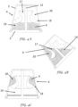
- One such embodiment of the tilt-indicating device is shown in Figures 4A-4C .
- the device In Figure 4A , the device is in an upright position in which the reservoir 19 is beneath the display chamber 20.
- the indicator fluid 9 is all contained within the reservoir 19. Tilting the device ( Figure 4B ) from the upright position to a tilted position in which at least some of the display chamber 20 is below at least part of the reservoir 19 permits indicator fluid to flow from the reservoir through the feed passage 17 to the display chamber at a first speed.
- the flow control member 1 has a larger central space 27, some of which is available to allow extra volume for liquid within the container 7 when the device is mounted in a container.
- the housing 3 (not shown in Figures 5 and 6 for clarity) makes a sealing fit with the outer circumference of the flow control member and defines an annular space with the base 2 within which indicator fluid is contained.
- the flow control member 1 is supported by a plurality of support members 12 on the base.
- the flow control member 1 has a floor 22 which slopes from a first end 21A to a second end 21B.
- a single return passage 18 from the floor 22 allows indicator fluid 9 to drain slowly from the display chamber 20.
- the diameter of the return passage 18 may in one embodiment be in the range 0.25 mm to 1 mm, notably 0.4 to 0.6 mm, and the length may in one embodiment in the range 1 to 6 mm, notably 2.5 to 4.5 mm. Preferred dimensions will depend on the flow characteristics of the indicator fluid and the desired dwell time.
- a further embodiment of the drinking vessel 100 includes a flexible tilt-indicating device, which is applied to an external surface of the container wall 8 and which will be referred to by reference number 16.
- This second embodiment is similar to previous embodiments, using a viscous liquid as an indicator fluid to show whether a user has had a drink within a pre-set time period, but comprises a retrofit device16 that may be affixed in use onto any existing drinking container 7.
- the device 16 has internal structures 11 which cooperate with walls 13 of the device to define a reservoir 19, one or more display chambers 20, one or more feed passages 17, and one or more return passages 18.
- the device 16 comprises an adhesive surface 28 with a peelable backing sheet 15.
- the or each display chamber is visible through transparent windows 14.
- a device array 23 comprises a plurality of tilt-indicating devices 16 on a backing sheet 15.
- the device array 23 may for example contain 10 or 16 adhesive stickers.
- each tilt-indicating device 16 is separated from a neighbouring tilt-indicating device by a portion of sheet material 15 provided with a line of scoring or perforation 24 to facilitate separation of one device 16 from the device array.
- the carer removes the backing 15 to uncover the adhesive surface 28, and affixes the tilt-indicating device 16 onto any drinking vessel or container.
- the indicator fluid 9 may have a green colouring to represent or indicate that the user has taken a drink.
- the adhesive backing is preferably strong enough to allow the flexible tilt-indicating device16 to be attached to any of a variety of containers and to resist fluids and be resistant to a dishwasher machine wash.
- the tilt-indicating device may be provided in or on a receptacle which has an opening for receiving the base of the container.
- the receptacle may, for example, be in the form of a ring, or a toroid, into which a conventional cup is inserted, the cup being a close fit for the opening of the receptacle so that the receptacle will be lifted when the cup is lifted.
Landscapes
- Physics & Mathematics (AREA)
- General Physics & Mathematics (AREA)
- Table Devices Or Equipment (AREA)
- Details Of Rigid Or Semi-Rigid Containers (AREA)
Description
- The present invention relates to a drinking vessel, in particular a drinking vessel which has a device for monitoring drinking. The drinking vessel is particularly but not exclusively, for monitoring liquid intake of vulnerable patients or the like.
- Increasingly ageing populations across many societies lead to problems in caring, particularly where ageing people become vulnerable.
- Maintaining liquid intake can be problematic for vulnerable persons, and by extension a problematic task for carers of vulnerable people.
- Carers need to ensure, often in busy environments, that their charges or users are maintaining hydration. Commercial solutions exist but such digital water trackers are expensive and focussed on a healthy living active lifestyle market.
-
CN 204 071 517 (LIU ) discloses a repeated water drinking reminding device. The repeated water drinking reminding device comprises a prompter and a cup body fixing device, wherein the prompter is an object, and different surfaces of the object have different colours, different patterns or different shapes; the prompter can rotate for 360 degrees. The prompter can be formed by a plurality of prompter parts which are separated from one another, and can be an integrated part of which different parts can rotate independently. The prompter and the cup body fixing device are connected. The surfaces with the different colours, the different patterns or the different shapes can be shown through the rotation of the prompter, so that one colour, one pattern or one shape is shown before a person drinks water, and another colour, another pattern or another shape is shown through the rotation after the person drinks water. The function of reminding the person to repeatedly drink water is realized by the change comparison of the colours, the patterns or the shapes. -
WO 201 524 575 (GUSTAFSSON -
CN 204 617 788 U discloses a drinking vessel according to the preamble ofclaim 1. This drinking vessel comprising a side wall defining an open topped container, and a base; and a tilt-indicating device for visibly indicating when the container has been tilted. - The present invention arose in order to overcome problems suffered by existing devices.
- According to the invention there is provided a drinking vessel as specified in
claim 1. Preferred features are specified in the dependent claims. - The invention provides a drinking vessel which incorporates a mechanism to indicate if it has not been drunk from for a period of time, for example around 2 hours.
- The indication may be visible from a distance, for example around 3-5 meters away. This distance may help to alert a care-giver or nurse if there is a risk that a client or patient may be getting dehydrated. In particular nurses move through wards quickly and need to easily identify those who are not drinking.
- The container may be dishwasher safe and does not require batteries or other external power sources. For example the drinking vessel and the tilt-indicating device may be able to withstand a wash cycle of between 61 and 70°C, with exposure to dishwash chemicals, followed by a rinse cycle at no less than 82°C for no less than 10 seconds. The drinking vessel and tilt-indicating device must also be able to work in environments such as hospital wards which tend to be very warm.
- The drinking vessel may thereby be arranged, styled and constructed for hospital or care-home patients/residents, particularly elderly people.
- Some embodiments of the device may comprise a plastic cup, similar in form to existing hospital/care-home plastic cups, with the ability to make a nurse or carer aware if the patient has taken a drink within a 2 hour period that is started when the container has been filled. Preferred embodiments may be arranged to demonstrate how much someone is drinking but be more concerned with "if' the patient is drinking.
- The tilt-indication device may be arranged to be functional when the container is filled halfway and needs to be light as patients tend to be weak.
- The tilt-indication device may be arranged to be activated and able to show if a user has or has not taken a sip for the 2- hour period in which the water is in the container.
- Preferred embodiments are simple to ensure a practical price point, and lightweight to maximise usability for vulnerable or compromised users, and have a similar lifespan to existing cups so as to ensure cost-effectiveness.
- The indications may comprise analogue 100ml and 200ml indicator levels.
- In the preferred embodiments the drinking vessel does not require input or additional work for the nurse or carer and the device is easy to clean. In this way the invention enable nurses or carers to be more efficient by focusing their limited time on patients who are not drinking.
- The drinking vessel does not change its appearance merely because it has been lifted up; a change of appearance is triggered by tipping the drinking vessel or tilting the device.
- In use it may be envisaged that the container is liable to be filled halfway to be light as users may be envisaged to tend to be weak.
- Variant embodiments of the device may comprise a sippy-cup embodiment, or a dementia embodiment (using a red coloured container, because people with late stage dementia find a red glass easier to see). A standard embodiment may be a clear/white version with 100ml and 200ml indicator levels.
- The invention enables nurses and carers to be more efficient by focusing their limited time on patients who are not drinking.
- For medical aesthetic reasons the drinking vessel may be similar to existing cups used in hospital.
- The invention will now be further described, by way of example only, with reference to the following drawings, in which:
-
Figure 1 shows an exploded isometric view of a first embodiment of a drinking vessel in accordance with the present invention; -
Figure 2 shows a first isometric sectional view of the assembled embodiment shown inFigure 1 ; -
Figure 3 shows a second isometric sectional view of the assembled embodiment shown inFigure 1 ; -
Figures 4A-C show isometric sectional views of a tilt-indicating device in accordance with another aspect of the present invention; -
Figures 5-6 show, respectively, a top plan view and a perspective view of part of a tilt-indicating device in accordance with a further embodiment of an aspect of the present invention; -
Figure 7 shows a sectional view through the device ofFigures 5 and 6 , with a housing; -
Figure 8 shows isometric views of a drinking vessel in accordance with another embodiment of the present invention; -
Figures 9A and 9B show isometric views of the tilt-indicator device used for the device shown inFigure 8 ; and -
Figures 10A and 10B show further isometric views of tilt-indicator devices for the drinking vessel shown inFigure 8 . - With reference to the
first embodiment 100 shown inFigures 1-3 , there is provided a drinking vessel comprising asidewall 8 defining an open toppedcontainer 7, and abase 2. Thedrinking vessel 100 has a tilt-indicatingdevice 6 for visibly indicating when the container has been tilted, which will occur when a user tilts thecontainer 7 to take a drink. - The
device 6 is arranged to indicate if the container has not been drunk from within a specified time period, for example about 2 hours. This indication should be visible from around 3-5 meters away and would help to alert a care-giver or nurse if there is a risk that a client or patient may be getting dehydrated. The drinking vessel is dishwasher-safe and does not use batteries or other external power sources. The embodiment thereby provides acontainer 7 which may be a plastic cup similar in form to existing hospital/care-home plastic cups, with the ability to make a nurse or carer aware if the patient has taken a drink within a 2 hour period. - In this embodiment, the tilt-
indicator device 6 is permanently located inside thecontainer 7, in this example a 1.5mm thick injection mouldedpolypropylene container 7 which is transparent or translucent. Thedevice 6 in this embodiment has asupport member 12 provided on thebase 2. Aflow control member 1 is mounted on thesupport member 12, and ahousing 3 is located over theflow control member 1 andsupport member 12, forming a fluid-tight seal with thebase 2. Thehousing 3 has a transparent ortranslucent portion 4 which provides a viewing window so that part of the inside of thehousing 3 is visible through thecontainer sidewall 8. - Referring to
Figure 2 , the volume beneath theflow control member 1 defines areservoir 19 within which is anindicator fluid 9, in this example a viscous liquid such as glycerol, a sol or a gel. The indicator fluid could alternatively comprise a fine particulate material such as a powder or sand which will flow freely under gravity. The indicator fluid preferably includes a colouring agent for ease of visibility. - The
flow control member 1 in this embodiment has awaist portion 25 which co-operates with an inner surface of theviewing window 4 to define adisplay chamber 20 which is visible through thecontainer sidewall 8. - The
flow control member 1 has a hollow tubular core which provides afeed passage 17 through whichindicator fluid 9 can freely flowfrom thereservoir 19 to the upper part of the inside of thehousing 3 and into thedisplay chamber 20 when thecontainer 7 is sufficiently tilted. Part of the flow control member 1 (in this example the lowest circumferential portion 26) co-operates with an internal surface of thehousing 3 to define areturn passage 18 which permitsindicator fluid 9 to drain from thedisplay chamber 20 to thereservoir 19. - The
return passage 18 is narrow relative to thefeed passage 17.Indicator fluid 9 can flow through thefeed passage 17 at a first speed and can drain through thereturn passage 18 at a second speed which is slower than the first speed. It will be appreciated that the size of thereturn passage 18 can be selected to allow a specific indicator fluid to pass through within a pre-set time, for example two hours. Without limiting the invention, the size of thereturn passage 18 might be determined by a gap between theflow control member 1 and the internal surface of the housing in the range 0.25 mm to 1 mm, notably 0.5 mm to 0.75 mm. - As the user tilts the
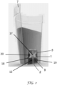
container 7, to take a drink (Figure 3 ).Indicator fluid 9 flows from thereservoir 19 through thefeed passage 18 and into thedisplay chamber 20 relatively quickly, for example within 2-4 seconds. When thecontainer 7 is returned to an upright position, indicator fluid drains slowly from thedisplay chamber 20 through thereturn passage 18 over a period of about two hours. Theindicator fluid 9 may be, for example, a viscous liquid which is bright green in colour and will be visible in lighter and darker environments. - When the indicator fluid is all within the
reservoir 19, notably when the drinking vessel has been on a flat surface for two hours or more, the green liquid sits inactive and non-visible for the user. The visible presence ofindicator fluid 9 in thedisplay chamber 20 is evidence of a user having taken a drink from the container within the preceding two hours. In this way a carer may monitor whether regular sips are taken. - In manufacture the
device 6 in this embodiment is assembled on thebase 2 and inserted into acavity 5 at the bottom of thecontainer wall 8 and then permanently secured, for example via sonic welding. Accordingly, thebase 2 in this example is common to thecontainer 7 and the tilt-indicator device 6. - In other embodiments, the
device 6 may be assembled and fixed to the base of aconventional container 7 by sonic welding or other appropriate means. One such embodiment of the tilt-indicating device is shown inFigures 4A-4C . InFigure 4A , the device is in an upright position in which thereservoir 19 is beneath thedisplay chamber 20. Theindicator fluid 9 is all contained within thereservoir 19. Tilting the device (Figure 4B ) from the upright position to a tilted position in which at least some of thedisplay chamber 20 is below at least part of thereservoir 19 permits indicator fluid to flow from the reservoir through thefeed passage 17 to the display chamber at a first speed. - Returning the device from the tilted position to the upright position (
Figure 4C ) permitsindicator fluid 9 to flow from thedisplay chamber 20 to thereservoir 19 through thereturn passage 18 as a second speed which is slower than the first speed. - Referring now to
Figures 5-7 , a further embodiment of a tilt-indicating device is illustrated. In this embodiment, theflow control member 1 has a largercentral space 27, some of which is available to allow extra volume for liquid within thecontainer 7 when the device is mounted in a container. The housing 3 (not shown inFigures 5 and 6 for clarity) makes a sealing fit with the outer circumference of the flow control member and defines an annular space with thebase 2 within which indicator fluid is contained. Theflow control member 1 is supported by a plurality ofsupport members 12 on the base. - The
flow control member 1 has afloor 22 which slopes from afirst end 21A to asecond end 21B. Asingle return passage 18 from thefloor 22 allowsindicator fluid 9 to drain slowly from thedisplay chamber 20. Without wishing to limit the invention, the diameter of thereturn passage 18 may in one embodiment be in the range 0.25 mm to 1 mm, notably 0.4 to 0.6 mm, and the length may in one embodiment in therange 1 to 6 mm, notably 2.5 to 4.5 mm. Preferred dimensions will depend on the flow characteristics of the indicator fluid and the desired dwell time. - It will be appreciated that other arrangements are possible, in which a plurality of
passages 18 are provided in theflow control member 1, depending on the nature of theindicator fluid 9 and the desired dwell time for the indicator fluid in the display chamber. - Referring now to
Figure 8 , a further embodiment of thedrinking vessel 100 includes a flexible tilt-indicating device, which is applied to an external surface of thecontainer wall 8 and which will be referred to byreference number 16. - This second embodiment is similar to previous embodiments, using a viscous liquid as an indicator fluid to show whether a user has had a drink within a pre-set time period, but comprises a retrofit device16 that may be affixed in use onto any existing
drinking container 7. - As shown in
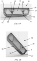
Figures 9A and 9B , thedevice 16 hasinternal structures 11 which cooperate withwalls 13 of the device to define areservoir 19, one ormore display chambers 20, one ormore feed passages 17, and one ormore return passages 18. - Referring now to
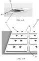
Figures 10A and 10B , thedevice 16 comprises anadhesive surface 28 with apeelable backing sheet 15. The or each display chamber is visible throughtransparent windows 14. In the embodiment ofFigure 10B , adevice array 23 comprises a plurality of tilt-indicatingdevices 16 on abacking sheet 15. Thedevice array 23 may for example contain 10 or 16 adhesive stickers. Preferably each tilt-indicatingdevice 16 is separated from a neighbouring tilt-indicating device by a portion ofsheet material 15 provided with a line of scoring orperforation 24 to facilitate separation of onedevice 16 from the device array. After separating adevice 16, the carer removes thebacking 15 to uncover theadhesive surface 28, and affixes the tilt-indicatingdevice 16 onto any drinking vessel or container. - The
indicator fluid 9 may have a green colouring to represent or indicate that the user has taken a drink. In the illustrated embodiment, there are twoclear viewing windows 14 that are situated over both thetriangular display chambers 20, which are spaced apart byinternal structures 11. This is to make the alert visible from multiple angles for the doctor or nurse depending on the position that the user places the container down to rest, wherein a window being empty is an indicator or alert that the user has not had a drink in the last two hours. - The adhesive backing is preferably strong enough to allow the flexible tilt-indicating device16 to be attached to any of a variety of containers and to resist fluids and be resistant to a dishwasher machine wash.
- In another embodiment, the tilt-indicating device may be provided in or on a receptacle which has an opening for receiving the base of the container. The receptacle may, for example, be in the form of a ring, or a toroid, into which a conventional cup is inserted, the cup being a close fit for the opening of the receptacle so that the receptacle will be lifted when the cup is lifted.
- The articles 'a' and 'an' are used herein to mean 'at least one' unless the context requires otherwise.
- The invention has been described by way of examples only and it will be appreciated that variation may be made to the above-mentioned embodiments without departing from the scope of invention as defined by the claims.
Claims (11)
- A drinking vessel (100) comprising a side wall (8) defining an open topped container (7), and a base (2); and a tilt-indicating device (6, 16) for visibly indicating when the container (7) has been tilted; characterised in that the tilt-indicating device (6, 16) comprises:a reservoir (19) and a display chamber (20);an indicator fluid (9) in the reservoir (19);a feed passage (17) connecting the reservoir (19) and the display chamber (20); anda return passage (18) which permits indicator fluid (9) to drain from the display chamber (20) to the reservoir (19); whereintilting of the container (7) from an upright position permits indicator fluid (9) to flow from the reservoir (19) through the feed passage (17) to the display chamber (20) at a first speed, andreturning the container (7) from a tilted position to the upright position permits indicator fluid (9) to flow from the display chamber (20) to the reservoir (19) through the return passage (18) at a second speed which is slower than the first speed.
- A drinking vessel according to claim 1, wherein the indicator fluid (9) includes a colouring agent.
- A drinking vessel according to claim 1, wherein the indicator fluid (9) is green in colour.
- A drinking vessel according to any one of the preceding claims, wherein the indicator fluid (9) is a viscous liquid.
- A drinking vessel according to any one of the preceding claims, wherein the tilt-indicating device (6) includes a housing (3) and a flow control member (1) within the housing (3); the return passage (18) being disposed through part of the flow control member (1) or being defined between part of the flow control member (1) and an internal surface of the housing (3).
- A drinking vessel according to any one of the preceding claims, wherein the side wall (8) is formed from a transparent or translucent material and the tilt-indicating device (6) is located inside the container (7).
- A drinking vessel according to claim 6, wherein the display chamber (20) is annular.
- A drinking vessel according to claim 7, wherein the return passage (18) is provided at a single location within the display chamber (20), and wherein the display chamber (20) has a floor which slopes downwardly from a point on the display chamber (20) opposite the return passage (18).
- A drinking vessel according to any one of claims 6-8, wherein the return passage (18) is located closer to the side wall (8) of the container (7) than is the feed passage (17).
- A drinking vessel according to any one of the preceding claims, wherein the side wall (8) of the container (7) has a red colour.
- A drinking vessel according to any one of claims 1-5, wherein the tilt-indicating device (16) is affixed to the side wall (8) of the container (7) by an adhesive material.
Applications Claiming Priority (2)
| Application Number | Priority Date | Filing Date | Title |
|---|---|---|---|
| GBGB1707985.6A GB201707985D0 (en) | 2017-05-18 | 2017-05-18 | A drinking device |
| PCT/IB2018/052678 WO2018211339A1 (en) | 2017-05-18 | 2018-04-18 | Drinking vessel with tilt-indicating device |
Publications (3)
| Publication Number | Publication Date |
|---|---|
| EP3624647A1 EP3624647A1 (en) | 2020-03-25 |
| EP3624647B1 true EP3624647B1 (en) | 2023-09-20 |
| EP3624647C0 EP3624647C0 (en) | 2023-09-20 |
Family
ID=59220676
Family Applications (1)
| Application Number | Title | Priority Date | Filing Date |
|---|---|---|---|
| EP18721862.3A Active EP3624647B1 (en) | 2017-05-18 | 2018-04-18 | Drinking vessel with tilt-indicating device |
Country Status (3)
| Country | Link |
|---|---|
| EP (1) | EP3624647B1 (en) |
| GB (1) | GB201707985D0 (en) |
| WO (1) | WO2018211339A1 (en) |
Families Citing this family (2)
| Publication number | Priority date | Publication date | Assignee | Title |
|---|---|---|---|---|
| US11829839B2 (en) * | 2019-11-16 | 2023-11-28 | Carlo St. Regis | Gear train design enabling mechanical accelerometers and latches |
| DE102021102510B3 (en) | 2021-02-03 | 2021-12-09 | Thomas Haupt | Analog display device for displaying a quantity of liquid to be dispensed from a container |
Family Cites Families (10)
| Publication number | Priority date | Publication date | Assignee | Title |
|---|---|---|---|---|
| JPS4853980U (en) * | 1971-10-26 | 1973-07-12 | ||
| DE2558403C2 (en) * | 1975-12-23 | 1984-09-20 | Wolfgang 7102 Weinsberg Seitz | Drinking vessel, especially beer glass |
| JPS61204577U (en) * | 1985-06-13 | 1986-12-23 | ||
| JPH0489074U (en) * | 1990-12-10 | 1992-08-03 | ||
| DE29710177U1 (en) * | 1997-06-11 | 1997-12-04 | Fischer, Peter, Dipl.-Phys. Dr.med., 53227 Bonn | hourglass |
| WO2015024575A1 (en) | 2013-08-19 | 2015-02-26 | Portable Axxelerated Media Sweden Ab | Intelligent cup or cup holder |
| IL230670A0 (en) * | 2014-01-27 | 2014-04-30 | Ashkan Aghajani | Elapsed time indicator |
| CN204071517U (en) | 2014-07-15 | 2015-01-07 | 刘荃荃 | Repeatedly drink water alarm set |
| CN204617788U (en) * | 2015-05-18 | 2015-09-09 | 徐建家 | The water tumbler of tool prompting drinking water function |
| US9619991B1 (en) * | 2016-07-19 | 2017-04-11 | Bashir Roohani | Method and apparatus for using water to disable an alarm clock |
-
2017
- 2017-05-18 GB GBGB1707985.6A patent/GB201707985D0/en not_active Ceased
-
2018
- 2018-04-18 EP EP18721862.3A patent/EP3624647B1/en active Active
- 2018-04-18 WO PCT/IB2018/052678 patent/WO2018211339A1/en not_active Ceased
Also Published As
| Publication number | Publication date |
|---|---|
| WO2018211339A1 (en) | 2018-11-22 |
| GB201707985D0 (en) | 2017-07-05 |
| EP3624647C0 (en) | 2023-09-20 |
| EP3624647A1 (en) | 2020-03-25 |
Similar Documents
| Publication | Publication Date | Title |
|---|---|---|
| US6793094B2 (en) | Anti-tipping container for liquids and semi-solid foods | |
| US7554434B1 (en) | Electronic indicator system for medicine bottle | |
| EP3589924B1 (en) | Drinking apparatus, system and associated methods | |
| US7963692B2 (en) | Monitoring apparatus | |
| JP2005529801A (en) | Container / bottle cap with storage room | |
| US20090050514A1 (en) | Dual compartment medicine container | |
| EP0591494A1 (en) | Thermally insulated baby bottle | |
| JP2010516584A (en) | wine glass | |
| EP3624647B1 (en) | Drinking vessel with tilt-indicating device | |
| MXPA05000514A (en) | Method and apparatus for metering liquid nutritional supplements. | |
| WO2021163207A1 (en) | Cup having measurement indicators | |
| CN107105909B (en) | Drinking utensils with compensation body | |
| US8262282B2 (en) | Monitoring apparatus | |
| US5045076A (en) | Disposable insulated surgical basins | |
| US20060124718A1 (en) | Dual-purpose cup | |
| US11672737B1 (en) | Medicine cup apparatus with ring attachment | |
| KR20120005056U (en) | cap for medicine vessel with inform part | |
| KR20140090827A (en) | apparatus for contain liquid with medicine admistration timer | |
| CN213373072U (en) | Thyroid gland postoperative is with bedside first-aid kit | |
| CN207803968U (en) | A kind of tumbler cup | |
| JPH0329661A (en) | Medicine container | |
| CN209575296U (en) | A kind of Portable medicine box | |
| KR200243793Y1 (en) | Diet bowl | |
| JP6311103B1 (en) | Cumulative capacity display container | |
| US20060102649A1 (en) | Good Cup |
Legal Events
| Date | Code | Title | Description |
|---|---|---|---|
| STAA | Information on the status of an ep patent application or granted ep patent |
Free format text: STATUS: UNKNOWN |
|
| STAA | Information on the status of an ep patent application or granted ep patent |
Free format text: STATUS: THE INTERNATIONAL PUBLICATION HAS BEEN MADE |
|
| PUAI | Public reference made under article 153(3) epc to a published international application that has entered the european phase |
Free format text: ORIGINAL CODE: 0009012 |
|
| STAA | Information on the status of an ep patent application or granted ep patent |
Free format text: STATUS: REQUEST FOR EXAMINATION WAS MADE |
|
| 17P | Request for examination filed |
Effective date: 20191023 |
|
| AK | Designated contracting states |
Kind code of ref document: A1 Designated state(s): AL AT BE BG CH CY CZ DE DK EE ES FI FR GB GR HR HU IE IS IT LI LT LU LV MC MK MT NL NO PL PT RO RS SE SI SK SM TR |
|
| AX | Request for extension of the european patent |
Extension state: BA ME |
|
| DAV | Request for validation of the european patent (deleted) | ||
| DAX | Request for extension of the european patent (deleted) | ||
| GRAP | Despatch of communication of intention to grant a patent |
Free format text: ORIGINAL CODE: EPIDOSNIGR1 |
|
| STAA | Information on the status of an ep patent application or granted ep patent |
Free format text: STATUS: GRANT OF PATENT IS INTENDED |
|
| INTG | Intention to grant announced |
Effective date: 20230413 |
|
| GRAS | Grant fee paid |
Free format text: ORIGINAL CODE: EPIDOSNIGR3 |
|
| GRAA | (expected) grant |
Free format text: ORIGINAL CODE: 0009210 |
|
| STAA | Information on the status of an ep patent application or granted ep patent |
Free format text: STATUS: THE PATENT HAS BEEN GRANTED |
|
| AK | Designated contracting states |
Kind code of ref document: B1 Designated state(s): AL AT BE BG CH CY CZ DE DK EE ES FI FR GB GR HR HU IE IS IT LI LT LU LV MC MK MT NL NO PL PT RO RS SE SI SK SM TR |
|
| REG | Reference to a national code |
Ref country code: GB Ref legal event code: FG4D |
|
| REG | Reference to a national code |
Ref country code: CH Ref legal event code: EP |
|
| REG | Reference to a national code |
Ref country code: IE Ref legal event code: FG4D |
|
| REG | Reference to a national code |
Ref country code: DE Ref legal event code: R096 Ref document number: 602018057877 Country of ref document: DE |
|
| U01 | Request for unitary effect filed |
Effective date: 20231018 |
|
| U07 | Unitary effect registered |
Designated state(s): AT BE BG DE DK EE FI FR IT LT LU LV MT NL PT SE SI Effective date: 20231025 |
|
| PG25 | Lapsed in a contracting state [announced via postgrant information from national office to epo] |
Ref country code: GR Free format text: LAPSE BECAUSE OF FAILURE TO SUBMIT A TRANSLATION OF THE DESCRIPTION OR TO PAY THE FEE WITHIN THE PRESCRIBED TIME-LIMIT Effective date: 20231221 |
|
| PG25 | Lapsed in a contracting state [announced via postgrant information from national office to epo] |
Ref country code: RS Free format text: LAPSE BECAUSE OF FAILURE TO SUBMIT A TRANSLATION OF THE DESCRIPTION OR TO PAY THE FEE WITHIN THE PRESCRIBED TIME-LIMIT Effective date: 20230920 Ref country code: NO Free format text: LAPSE BECAUSE OF FAILURE TO SUBMIT A TRANSLATION OF THE DESCRIPTION OR TO PAY THE FEE WITHIN THE PRESCRIBED TIME-LIMIT Effective date: 20231220 Ref country code: HR Free format text: LAPSE BECAUSE OF FAILURE TO SUBMIT A TRANSLATION OF THE DESCRIPTION OR TO PAY THE FEE WITHIN THE PRESCRIBED TIME-LIMIT Effective date: 20230920 Ref country code: GR Free format text: LAPSE BECAUSE OF FAILURE TO SUBMIT A TRANSLATION OF THE DESCRIPTION OR TO PAY THE FEE WITHIN THE PRESCRIBED TIME-LIMIT Effective date: 20231221 |
|
| PG25 | Lapsed in a contracting state [announced via postgrant information from national office to epo] |
Ref country code: IS Free format text: LAPSE BECAUSE OF FAILURE TO SUBMIT A TRANSLATION OF THE DESCRIPTION OR TO PAY THE FEE WITHIN THE PRESCRIBED TIME-LIMIT Effective date: 20240120 |
|
| PG25 | Lapsed in a contracting state [announced via postgrant information from national office to epo] |
Ref country code: ES Free format text: LAPSE BECAUSE OF FAILURE TO SUBMIT A TRANSLATION OF THE DESCRIPTION OR TO PAY THE FEE WITHIN THE PRESCRIBED TIME-LIMIT Effective date: 20230920 |
|
| PG25 | Lapsed in a contracting state [announced via postgrant information from national office to epo] |
Ref country code: SM Free format text: LAPSE BECAUSE OF FAILURE TO SUBMIT A TRANSLATION OF THE DESCRIPTION OR TO PAY THE FEE WITHIN THE PRESCRIBED TIME-LIMIT Effective date: 20230920 Ref country code: RO Free format text: LAPSE BECAUSE OF FAILURE TO SUBMIT A TRANSLATION OF THE DESCRIPTION OR TO PAY THE FEE WITHIN THE PRESCRIBED TIME-LIMIT Effective date: 20230920 Ref country code: IS Free format text: LAPSE BECAUSE OF FAILURE TO SUBMIT A TRANSLATION OF THE DESCRIPTION OR TO PAY THE FEE WITHIN THE PRESCRIBED TIME-LIMIT Effective date: 20240120 Ref country code: ES Free format text: LAPSE BECAUSE OF FAILURE TO SUBMIT A TRANSLATION OF THE DESCRIPTION OR TO PAY THE FEE WITHIN THE PRESCRIBED TIME-LIMIT Effective date: 20230920 Ref country code: CZ Free format text: LAPSE BECAUSE OF FAILURE TO SUBMIT A TRANSLATION OF THE DESCRIPTION OR TO PAY THE FEE WITHIN THE PRESCRIBED TIME-LIMIT Effective date: 20230920 Ref country code: SK Free format text: LAPSE BECAUSE OF FAILURE TO SUBMIT A TRANSLATION OF THE DESCRIPTION OR TO PAY THE FEE WITHIN THE PRESCRIBED TIME-LIMIT Effective date: 20230920 |
|
| U20 | Renewal fee for the european patent with unitary effect paid |
Year of fee payment: 7 Effective date: 20240425 |
|
| PG25 | Lapsed in a contracting state [announced via postgrant information from national office to epo] |
Ref country code: PL Free format text: LAPSE BECAUSE OF FAILURE TO SUBMIT A TRANSLATION OF THE DESCRIPTION OR TO PAY THE FEE WITHIN THE PRESCRIBED TIME-LIMIT Effective date: 20230920 |
|
| REG | Reference to a national code |
Ref country code: DE Ref legal event code: R097 Ref document number: 602018057877 Country of ref document: DE |
|
| PLBE | No opposition filed within time limit |
Free format text: ORIGINAL CODE: 0009261 |
|
| STAA | Information on the status of an ep patent application or granted ep patent |
Free format text: STATUS: NO OPPOSITION FILED WITHIN TIME LIMIT |
|
| 26N | No opposition filed |
Effective date: 20240621 |
|
| PG25 | Lapsed in a contracting state [announced via postgrant information from national office to epo] |
Ref country code: MC Free format text: LAPSE BECAUSE OF FAILURE TO SUBMIT A TRANSLATION OF THE DESCRIPTION OR TO PAY THE FEE WITHIN THE PRESCRIBED TIME-LIMIT Effective date: 20230920 |
|
| PG25 | Lapsed in a contracting state [announced via postgrant information from national office to epo] |
Ref country code: MC Free format text: LAPSE BECAUSE OF FAILURE TO SUBMIT A TRANSLATION OF THE DESCRIPTION OR TO PAY THE FEE WITHIN THE PRESCRIBED TIME-LIMIT Effective date: 20230920 |
|
| REG | Reference to a national code |
Ref country code: CH Ref legal event code: PL |
|
| PG25 | Lapsed in a contracting state [announced via postgrant information from national office to epo] |
Ref country code: CH Free format text: LAPSE BECAUSE OF NON-PAYMENT OF DUE FEES Effective date: 20240430 |
|
| PG25 | Lapsed in a contracting state [announced via postgrant information from national office to epo] |
Ref country code: IE Free format text: LAPSE BECAUSE OF NON-PAYMENT OF DUE FEES Effective date: 20240418 |
|
| U20 | Renewal fee for the european patent with unitary effect paid |
Year of fee payment: 8 Effective date: 20250423 |
|
| PGFP | Annual fee paid to national office [announced via postgrant information from national office to epo] |
Ref country code: GB Payment date: 20250423 Year of fee payment: 8 |
|
| PG25 | Lapsed in a contracting state [announced via postgrant information from national office to epo] |
Ref country code: CY Free format text: LAPSE BECAUSE OF FAILURE TO SUBMIT A TRANSLATION OF THE DESCRIPTION OR TO PAY THE FEE WITHIN THE PRESCRIBED TIME-LIMIT; INVALID AB INITIO Effective date: 20180418 |
|
| PG25 | Lapsed in a contracting state [announced via postgrant information from national office to epo] |
Ref country code: HU Free format text: LAPSE BECAUSE OF FAILURE TO SUBMIT A TRANSLATION OF THE DESCRIPTION OR TO PAY THE FEE WITHIN THE PRESCRIBED TIME-LIMIT; INVALID AB INITIO Effective date: 20180418 |