EP3624550A1 - Deployment of a wireless aircraft network - Google Patents
Deployment of a wireless aircraft network Download PDFInfo
- Publication number
- EP3624550A1 EP3624550A1 EP19197107.6A EP19197107A EP3624550A1 EP 3624550 A1 EP3624550 A1 EP 3624550A1 EP 19197107 A EP19197107 A EP 19197107A EP 3624550 A1 EP3624550 A1 EP 3624550A1
- Authority
- EP
- European Patent Office
- Prior art keywords
- wireless
- channel
- network
- sensors
- data
- Prior art date
- Legal status (The legal status is an assumption and is not a legal conclusion. Google has not performed a legal analysis and makes no representation as to the accuracy of the status listed.)
- Granted
Links
Images


Classifications
-
- H—ELECTRICITY
- H04—ELECTRIC COMMUNICATION TECHNIQUE
- H04W—WIRELESS COMMUNICATION NETWORKS
- H04W48/00—Access restriction; Network selection; Access point selection
- H04W48/16—Discovering, processing access restriction or access information
-
- H—ELECTRICITY
- H04—ELECTRIC COMMUNICATION TECHNIQUE
- H04W—WIRELESS COMMUNICATION NETWORKS
- H04W40/00—Communication routing or communication path finding
- H04W40/02—Communication route or path selection, e.g. power-based or shortest path routing
- H04W40/04—Communication route or path selection, e.g. power-based or shortest path routing based on wireless node resources
- H04W40/08—Communication route or path selection, e.g. power-based or shortest path routing based on wireless node resources based on transmission power
-
- H—ELECTRICITY
- H04—ELECTRIC COMMUNICATION TECHNIQUE
- H04B—TRANSMISSION
- H04B7/00—Radio transmission systems, i.e. using radiation field
- H04B7/14—Relay systems
- H04B7/15—Active relay systems
- H04B7/185—Space-based or airborne stations; Stations for satellite systems
- H04B7/18502—Airborne stations
- H04B7/18506—Communications with or from aircraft, i.e. aeronautical mobile service
-
- H—ELECTRICITY
- H04—ELECTRIC COMMUNICATION TECHNIQUE
- H04W—WIRELESS COMMUNICATION NETWORKS
- H04W40/00—Communication routing or communication path finding
- H04W40/02—Communication route or path selection, e.g. power-based or shortest path routing
- H04W40/04—Communication route or path selection, e.g. power-based or shortest path routing based on wireless node resources
- H04W40/10—Communication route or path selection, e.g. power-based or shortest path routing based on wireless node resources based on available power or energy
-
- H—ELECTRICITY
- H04—ELECTRIC COMMUNICATION TECHNIQUE
- H04W—WIRELESS COMMUNICATION NETWORKS
- H04W52/00—Power management, e.g. Transmission Power Control [TPC] or power classes
- H04W52/04—Transmission power control [TPC]
- H04W52/30—Transmission power control [TPC] using constraints in the total amount of available transmission power
- H04W52/36—Transmission power control [TPC] using constraints in the total amount of available transmission power with a discrete range or set of values, e.g. step size, ramping or offsets
- H04W52/365—Power headroom reporting
-
- H—ELECTRICITY
- H04—ELECTRIC COMMUNICATION TECHNIQUE
- H04W—WIRELESS COMMUNICATION NETWORKS
- H04W76/00—Connection management
- H04W76/10—Connection setup
- H04W76/15—Setup of multiple wireless link connections
-
- H—ELECTRICITY
- H04—ELECTRIC COMMUNICATION TECHNIQUE
- H04L—TRANSMISSION OF DIGITAL INFORMATION, e.g. TELEGRAPHIC COMMUNICATION
- H04L12/00—Data switching networks
- H04L12/28—Data switching networks characterised by path configuration, e.g. LAN [Local Area Networks] or WAN [Wide Area Networks]
- H04L12/40—Bus networks
- H04L2012/40267—Bus for use in transportation systems
- H04L2012/4028—Bus for use in transportation systems the transportation system being an aircraft
-
- H—ELECTRICITY
- H04—ELECTRIC COMMUNICATION TECHNIQUE
- H04W—WIRELESS COMMUNICATION NETWORKS
- H04W48/00—Access restriction; Network selection; Access point selection
- H04W48/17—Selecting a data network PoA [Point of Attachment]
-
- H—ELECTRICITY
- H04—ELECTRIC COMMUNICATION TECHNIQUE
- H04W—WIRELESS COMMUNICATION NETWORKS
- H04W84/00—Network topologies
- H04W84/02—Hierarchically pre-organised networks, e.g. paging networks, cellular networks, WLAN [Wireless Local Area Network] or WLL [Wireless Local Loop]
- H04W84/04—Large scale networks; Deep hierarchical networks
- H04W84/06—Airborne or Satellite Networks
Definitions
- Exemplary embodiments pertain to the art of avionics communication and more particularly to deployment of a wireless aircraft network.
- aircraft communication is predominantly wired using point-to-point wired connections and/or bus connections.
- aircraft systems communicate with each other through a standard, wired interface such as, for example, avionic buses CAN, Ethernet, and the like.
- wired interfaces electromagnetic interferences is relatively minimal and network deployment primarily involves configuration of network elements and message scheduling.
- deployment of wired network application involves significant manual effort, leading to sub-optimal network configurations and higher deployment time and costs.
- scalability of large wired networks may be limited by challenges in cable routing and associated certification activities.
- an exemplary avionic wireless sensor system includes a plurality of wireless sensors, a plurality of wireless data controllers each including a processing circuit and memory, and a network controller configured to operate the plurality of wireless data controllers and to perform a wireless network deployment operation responsive to a deployment trigger, the wireless network deployment operation including scanning a plurality of wireless channels to determine an energy level for each channel in the plurality of wireless channels. Selecting a primary channel and a secondary channel from the plurality of wireless channels based at least in part on the energy level. Selecting a primary wireless controller and a secondary wireless data controller for each of the plurality of the wireless sensor nodes and establishing wireless communication with each of a plurality of wireless sensors over the primary channel and the secondary channel.
- further embodiments may include that establishing wireless communication with each of the plurality of wireless sensors over the primary channel and the secondary channel includes transmitting, by the plurality of wireless data controllers, a beacon signal to the plurality of wireless sensors on a pre-defined wireless channel, wherein each of the plurality of wireless sensors are configured to scan for the beacon signal periodically. Establishing wireless communication with each of the plurality of wireless sensors over the predefined channel.
- Transmitting credentialing data to the plurality of wireless sensors over the predefined channel responsive to receiving, from the plurality of wireless sensors, the credentialing data establishing a primary connection with each of the plurality of wireless sensors on the corresponding first wireless data controller on the primary channel and establishing a secondary connection with each of the plurality of wireless sensors on the corresponding second wireless data controller on the secondary channel.
- further embodiments may include that establishing the primary connection with the first wireless data controller is based on one or more signal characteristics of the primary channel on the first gateway device.
- further embodiments may include that the network controller is further configured to receive sensor configuration data from each of the plurality of wireless sensors, wherein the sensor data interface data comprises network parameters for the wireless sensor, store the sensor configuration data for each of the plurality of wireless sensors in a deployment matrix in the memory, and transmit the deployment matrix to each of the plurality of the wireless data controllers.
- further embodiments may include that the network controller is further configured to periodically obtain sensor configuration data from each of the plurality of wireless sensors, compare the obtained sensor configuration data to the sensor configuration data in the deployment matrix, and based on a determination that the obtained sensor configuration data does not match the sensor configuration data in the deployment matrix, triggering the wireless network deployment operation.
- determining the energy level for each channel in the plurality of wireless channels includes obtaining, by the plurality of wireless data controllers, a plurality of sample energy levels for each wireless channel and averaging the plurality of sample energy levels to determine the energy level for each channel in the plurality of wireless channels.
- further embodiments may include that the selecting the primary channel and the secondary channel includes comparing the energy level of each channel in the plurality of wireless channels to a calculated threshold to identify two or more candidate channels in the plurality of wireless channels that include energy levels below the calculate threshold, selecting the primary channel from the two or more candidate channels, and selecting the secondary channel from the two or more candidate channels, wherein the energy level for the primary channel is less than the energy level for the secondary channel.
- further embodiments may include that the plurality of wireless sensors are located on an aircraft.
- further embodiments may include that the network controller is further configured to trigger the wireless network deployment operation based at least in part on an operation of the aircraft.
- controller is further configured to trigger the wireless network deployment operation periodically.
- a method for deployment of a wireless network includes scanning, by a network controller, a plurality of wireless channels to determine an energy level for each channel in the plurality of wireless channels. Selecting a primary channel and a secondary channel from the plurality of wireless channels based at least in part on the energy level. Selecting a primary wireless controller and a secondary wireless data controller for each of the plurality of the wireless sensor nodes and establishing wireless communication with each of a plurality of wireless sensors over the primary channel and the secondary channel.
- further embodiments may include establishing wireless communication with each of the plurality of wireless sensors over the primary channel and the secondary channel includes transmitting, by a plurality of wireless data controllers, a beacon signal to the plurality of wireless sensors on a pre-defined wireless channel, wherein each of the plurality of wireless sensors are configured to scan for the beacon signal periodically, establishing wireless communication with each of the plurality of wireless sensors over the predefined channel, transmitting credentialing data to the plurality of wireless sensors over the predefined channel, and responsive to receiving, from the plurality of wireless sensors, the credentialing data establishing a primary connection with each of the plurality of wireless sensors on the first corresponding wireless data controller on the primary channel and establishing a secondary connection with each of the plurality of wireless sensors on the corresponding second wireless data controller on the secondary channel.
- further embodiments may include that establishing the primary connection with the first wireless data controller is based on one or more signal characteristics of the primary channel on the first gateway device.
- further embodiments may include receiving sensor configuration data from each of the plurality of wireless sensors, wherein the sensor data interface data comprises network parameters for the wireless sensor and storing the sensor configuration data for each of the plurality of wireless sensors in a deployment matrix in the memory.
- further embodiments may include periodically obtaining sensor configuration data from each of the plurality of wireless sensors, comparing the obtained sensor configuration data to the sensor configuration data in the deployment matrix, and based on a determination that the obtained sensor configuration data does not match the sensor configuration data in the deployment matrix, triggering a wireless network redeployment operation.
- determining the energy level for each channel in the plurality of wireless channels includes obtaining, by a plurality of wireless data controllers, a plurality of sample energy levels for each wireless channel and averaging the plurality of sample energy levels to determine the energy level for each channel in the plurality of wireless channels.
- further embodiments may include that the selecting the primary channel and the secondary channel includes comparing the energy level of each channel in the plurality of wireless channels to a calculated threshold to identify two or more candidate channels in the plurality of wireless channels that include energy levels below the calculate threshold, selecting the primary channel from the two or more candidate channels, and selecting the secondary channel from the two or more candidate channels, wherein the energy level for the primary channel is less than the energy level for the secondary channel.
- further embodiments may include that the plurality of wireless sensors are located on an aircraft.
- further embodiments may include triggering a wireless network redeployment operation based at least in part on an operation of the aircraft.
- further embodiments may include triggering a wireless network redeployment operation periodically.
- wireless networks on aircrafts present challenges. Some of these challenges include issues with establishing a seamless communication between network elements in the presence of electromagnetic interference from existing onboard radio communication systems for the aircraft (e.g., Wi-Fi and multi-path radio propagation due to the aircraft internal structure.) Another challenge includes issues with optimizing the network topology and deployment time for the application specific spatial distribution of the network elements and installation zones. Also, aircraft downtime for deployment of the wireless network elements can be costly.
- the disclosure now provides a process for automatically evaluating an aircraft environment and providing a deployment architecture for a wireless aircraft network to reduce network installation time and cost.
- This automated process defines network topology and configuration by selection of optimal wireless network channels. Also, this process allows for network re-configuration for the addition and removal of network nodes.
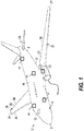
- FIG. 1 depicts a perspective view of an aircraft 2 that may incorporate embodiments of the present disclosure.
- Aircraft 2 includes a fuselage 4 extending from a nose portion 6 to a tail portion 8 through a body portion 10.
- Body portion 10 houses an aircraft cabin 14 that includes a crew compartment 15 and a passenger compartment 16.
- Body portion 10 supports a first wing 17 and a second wing 18.
- First wing 17 extends from a first root portion 20 to a first tip portion 21 through a first airfoil portion 23.
- First airfoil portion 23 includes a leading edge 25 and a trailing edge 26.
- Second wing 18 extends from a second root portion (not shown) to a second tip portion 31 through a second airfoil portion 33.
- Second airfoil portion 33 includes a leading edge 35 and a trailing edge 36.
- Tail portion 8 includes a stabilizer 38.
- Aircraft 2 includes an engine 54 configured to provide propulsion to the aircraft 2.
- the aircraft 2 includes one or more wireless data controllers 40 operable to establish wireless communication with a plurality of sensors 42.
- the sensors 42 can have the same or different characteristics in terms of data rates and priorities in the context of particular avionic applications. Some sensors 42 may only generate updated values several times per second, while other sensors 42 may generate hundreds or thousands of updated values per second. For instance, some sensor data can be event driven and other sensor data is continuously generated at a known interval. Further, some sensor data is exclusively used for monitoring but not control operations, while other sensor data may be used for both monitoring and control operations or exclusively for control operations on the aircraft 2.
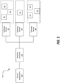
- FIG. 2 depicts a diagram of an avionic wireless sensor system according to one or more embodiments.
- the system 200 includes a network controller 202 that is configured to operate multiple wireless data controllers 40.
- the multiple wireless data controllers 40 can be wireless routers or switches deployed throughout an aircraft or other vehicle.
- the wireless data controllers 40 are operable to connect to sensors 42 via wireless networking protocols such as, for example, IEEE 802.15. As such, sensors 42 are referred to wireless sensors.
- the wireless sensors 42 can include a sensing means, a transceiver, and a battery or other power source.
- the wireless sensors 42 can transmit sensor data to the wireless data controllers 40 which are managed by the network controller 202.
- the network controller 202 can interface with one or more aircraft applications 220 and provide the sensor data received from the wireless sensors 42. While the illustrated example shows an airplane, any type of vehicle can be utilized for deployment of these wireless sensors including, but not limited to, helicopters, ships, and any other vehicle that may or may not have the potential for electromagnetic interference.
- the network controller 202, wireless data controllers 40, and sensors 42 can be implemented by executable instructions and/or circuitry such as a processing circuit and memory.
- the processing circuit can be embodied in any type of central processing unit (CPU), including a microprocessor, a digital signal processor (DSP), a microcontroller, an application specific integrated circuit (ASIC), a field programmable gate array (FPGA), or the like.
- the memory may include random access memory (RAM), read only memory (ROM), or other electronic, optical, magnetic, or any other computer readable medium onto which is stored data and algorithms as executable instructions in a non-transitory form.
- the network controller 202 is configured to deploy and re-deploy a wireless network that utilizes two channels to connect to each wireless sensor 42.
- Each of the wireless data controllers 40 can broadcast more than one channel for the sensors 42 to connect to.
- the wireless sensors 42 can connect to two of the wireless data controllers 40 based on signal characteristics for the data controllers 40 or any other characteristic such as proximity, for example.
- the network controller 202 can re-deploy the wireless network based on a wireless sensor 42 coming online or going offline or for any other reason such as, for example, a change in the aircraft operation or can be done periodically.
- FIG. 3 depicts a flow diagram of an exemplary method for deploying a wireless network.
- the method 300 begins at process step 302 which is the initiation of the network deployment.
- the network controller 202 Before connecting to any network nodes (e.g., wireless sensors 42), the network controller 202 first scans the energy level of the operating network channels to identify and select the two least energized network channels (primary and secondary) for use in the network, as shown at block 304. This process step 304 will be discussed in greater detail with reference to FIG. 4 .
- the process step 306 has the network controller 202 deploy the wireless network through the wireless data controllers 40 to connect to network nodes (e.g., wireless sensors 42).
- the network controller 202 can monitor the network nodes to determine, at decision block 308, whether a network node goes offline or comes back online. If a network node does get added/removed, the process step 310 is initiated and the network controller 202 automatically reconfigures the wireless network by proceeding to process step 310. If no network node is added/removed, the network controller 202 continues to operate the wireless network.
- reconfiguration process step 310 can be initiated based on reconfiguration trigger as shown in decision block 308. These triggers can include that a certain amount of time has elapsed, an operation of the aircraft, a user request, a change in energy level of the primary or secondary channel, and the like. For example, an operation of the aircraft that triggers a reconfiguration can include a change in altitude, a landing or take-off operation, environmental factors such weather, or at an aircraft user's request.
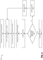
- FIG. 4 depicts a flow chart of a process for an energy level scan and selection of channels for deployment in the wireless network according to one or more embodiments.
- the process 304 begins with block 402 with the energy level scan and channel selection which can be initiated, as described above, by a network deployment or reconfiguration.
- the process 304 includes performing an energy detection for a wireless network channel.
- wireless network channel refers to a single path provided by a wireless transmission medium via electrical separation, such as, for example, by frequency division or time division multiplexing.
- the energy detection for the wireless network channel refers to the detection of the energy level present on a channel (frequency range) based on the noise floor, ambient energy, interference sources, and unidentifiable Wi-Fi transmissions that may have been corrupted or can no longer be decoded. Energy values are in units of decibels.
- the process 304 includes sampling energy values over N samples.
- the N samples can be set by the network controller 202 or predefined by a network administrator.
- the wireless data controllers 40 perform the energy level scan. The samples are averaged over the N samples to compute the energy value for the channel, as shown at block 408.
- An energy level threshold is calculated, at block 410, for comparison to the energy level calculated for the channel.
- the energy level threshold is utilized to determine if the channel is busy or idle.
- the method 304 compares the energy value for the channel to the energy level threshold to determine if the channel should be nominated or discarded. If the channel energy value is less than the threshold, the channel is nominated, as shown at block 414. If the channel energy value is above the threshold, the channel is discarded, as shown at block 416. A next channel is selected, at block 418, and the method 304 repeats until a certain number of channels have been nominated or if the method 304 runs out of channels.
- the network controller 202 selects the two network channels with the lowest energy levels from the nominated network channels.
- the two network channels can be referred to as a primary channel and a secondary channel for deployment in the wireless network.
- the primary channel and secondary channel provide for a redundant connection to the wireless network for the wireless sensors 42.
- Each of the wireless data controllers 40 can broadcast the primary channel and secondary channel.
- a particular wireless sensor 42 can connect to a primary channel though a first wireless data controller, and redundantly connect to the secondary channel through a second wireless data controller.
- the wireless sensor 42 can select the first and second wireless data controllers based on signal characteristic, proximity, and the like.
- FIG. 5 depicts a flow diagram of a method for configuration of the wireless network and generation of the deployment matrix according to one or more embodiments.
- the method 306 includes the start of the automatic configuration protocol, as shown at block 502.
- the configuration can begin when the primary and second network channels have been selected or can be done concurrently with the energy level scan and network channel selection.
- the network controller 202 through the wireless data controllers (WDC) 40, transmits a beacon on a predefined channel, as shown at block 504. This pre-defined channel is known to the wireless sensors 42.
- the wireless sensors 42 can periodically scan for this beacon transmission or can be sent an indication that triggers the scan for this beacon on the predefined channel and generates a sensor association matrix, as shown at block 506.
- This beacon can transmit credentialing information to each of the wireless sensors 42 that allows the wireless sensors 42 to connect to the wireless data controllers 40.
- the wireless sensors 42 can verify the quality and strength of the radio frequency signal for each wireless data controller 40 and can tag the identifiers (WDC IDs) of the wireless data controllers 40 based on their signal characteristics.
- the wireless sensors 42 identify and select the top two wireless data controllers 40 based on signal characteristic with one wireless data controller being designated as the primary channel data controller and the other wireless data controller being designated as the secondary channel data controller.
- the identifiers for these wireless data controllers are stored in the wireless sensor data memory.
- the credentialing information e.g., password, credentials, etc.
- the wireless sensor 42 associates with primary wireless data controller and secondary wireless data controller.
- the wireless sensor 42 can transmit sensor configuration data to the network controller 202.
- the sensor configuration data includes a sensor association matrix (SAM) and a sensor data interface (SDIx) description, as shown in the tables below.
- SAM sensor association matrix
- the sensor association matrix (SAM) includes the wireless sensor identifier and the identifiers of the primary and secondary WDCs.
- An example SAM is depicted in Table 1.
- each sensor includes information such as the sensor node ID, the number of sensing parameters, information about the sensing parameters as well as a data rate for the sensor.
- the sensor node 5 is a temperature sensor that returns temperature in units of Celsius at a data rate of 1 hertz.
- Table 2 Example Sensor Data Interface Sensor Node ID 5 No. of Parameters 1 Parameter Name Unit Data Rate Temperature Celsius 1 Hz
- the method 306 includes the network controller 202 generating a deployment matrix, as shown at block 512.
- An example deployment matrix is depicted in Table 3 below.
- the deployment matrix is created for each wireless data controller 40 and includes information about the wireless sensors connected through the wireless data controllers 40.
- the identifier for the WDC is included as well as the primary channel and the secondary channel.
- the maximum number of wireless sensors is stored in the deployment matrix along with the wireless sensor IDs for each node.
- the last column the sensor node description from the SDIx, as shown in table 2.
- Table 3 Example Deployment Matrix WDC ID Primary Channel Secondary Channel Max No. of Sensor Nodes Permitted Sensor Nodes SDIx description for Permitted Sensor Nodes C001 5 8 5 2, 5, 7, 11, 23 From Table 2
- the network controller 202 After the network controller generates the deployment matrix for each wireless data controller, the network controller 202 transmits the each respective deployment matrix to the WDCs, as shown in block 514.
- the network controller 202 also maintains the deployment matrix in a memory which can be utilized for reconfiguration. After completion of the network configuration, the network elements can be restarted to operate on the wireless network based on the configuration developed from this process 306.
- the network can be reconfigured and the primary and secondary channels can be adjusted based on the triggering of a redeployment.
- the redeployment can include a reconfiguration of the network elements as described in method 306, a rescan and reselection of a channels as described in method 304, or both.
- a redeployment can occur after an initial configuration of the wireless network, during every network boot up, the network controller 202 scans the physical configuration of the wireless data controllers 40 and the wireless sensors 42 and compares this with the deployment matrixes stored in the memory for the network controller 202. In case an additional wireless sensor is detected, an automatic network deployment is performed either for the new wireless sensors or for all wireless sensors.
- the deployment can be just the reconfiguration of the network or can include the channel assignment/selection. If a wireless sensor has been removed from the network, the network controller 202 can trigger a redeployment or can remove the wireless sensor from the deployment matrix.
Landscapes
- Engineering & Computer Science (AREA)
- Computer Networks & Wireless Communication (AREA)
- Signal Processing (AREA)
- Physics & Mathematics (AREA)
- Astronomy & Astrophysics (AREA)
- Aviation & Aerospace Engineering (AREA)
- General Physics & Mathematics (AREA)
- Computer Security & Cryptography (AREA)
- Mobile Radio Communication Systems (AREA)
- Quality & Reliability (AREA)
- Electromagnetism (AREA)
Abstract
Description
- Exemplary embodiments pertain to the art of avionics communication and more particularly to deployment of a wireless aircraft network.
- Architecture of aircraft is evolving based on application needs, customer needs, market segments and the availability of advanced technologies. In the process of making advanced technologies more available on aircraft, there are attempts to make aircraft more intelligent, more electrical and more data driven. Considering the cost of an aircraft design life cycle and operations, it is may be beneficial to have modular and re-usable architecture while still maintaining robustness and reliability. At present, aircraft communication is predominantly wired using point-to-point wired connections and/or bus connections. Typically, aircraft systems communicate with each other through a standard, wired interface such as, for example, avionic buses CAN, Ethernet, and the like. For wired interfaces, electromagnetic interferences is relatively minimal and network deployment primarily involves configuration of network elements and message scheduling. However, deployment of wired network application involves significant manual effort, leading to sub-optimal network configurations and higher deployment time and costs. Also, scalability of large wired networks may be limited by challenges in cable routing and associated certification activities.
- In accordance with an aspect of the invention, there is provided an exemplary avionic wireless sensor system. The system includes a plurality of wireless sensors, a plurality of wireless data controllers each including a processing circuit and memory, and a network controller configured to operate the plurality of wireless data controllers and to perform a wireless network deployment operation responsive to a deployment trigger, the wireless network deployment operation including scanning a plurality of wireless channels to determine an energy level for each channel in the plurality of wireless channels. Selecting a primary channel and a secondary channel from the plurality of wireless channels based at least in part on the energy level. Selecting a primary wireless controller and a secondary wireless data controller for each of the plurality of the wireless sensor nodes and establishing wireless communication with each of a plurality of wireless sensors over the primary channel and the secondary channel.
- In addition to one or more of the features described above, or as an alternative to any of the foregoing embodiments, further embodiments may include that establishing wireless communication with each of the plurality of wireless sensors over the primary channel and the secondary channel includes transmitting, by the plurality of wireless data controllers, a beacon signal to the plurality of wireless sensors on a pre-defined wireless channel, wherein each of the plurality of wireless sensors are configured to scan for the beacon signal periodically. Establishing wireless communication with each of the plurality of wireless sensors over the predefined channel. Transmitting credentialing data to the plurality of wireless sensors over the predefined channel responsive to receiving, from the plurality of wireless sensors, the credentialing data establishing a primary connection with each of the plurality of wireless sensors on the corresponding first wireless data controller on the primary channel and establishing a secondary connection with each of the plurality of wireless sensors on the corresponding second wireless data controller on the secondary channel.
- In addition to one or more of the features described above, or as an alternative to any of the foregoing embodiments, further embodiments may include that establishing the primary connection with the first wireless data controller is based on one or more signal characteristics of the primary channel on the first gateway device.
- In addition to one or more of the features described above, or as an alternative to any of the foregoing embodiments, further embodiments may include that the network controller is further configured to receive sensor configuration data from each of the plurality of wireless sensors, wherein the sensor data interface data comprises network parameters for the wireless sensor, store the sensor configuration data for each of the plurality of wireless sensors in a deployment matrix in the memory, and transmit the deployment matrix to each of the plurality of the wireless data controllers.
- In addition to one or more of the features described above, or as an alternative to any of the foregoing embodiments, further embodiments may include that the network controller is further configured to periodically obtain sensor configuration data from each of the plurality of wireless sensors, compare the obtained sensor configuration data to the sensor configuration data in the deployment matrix, and based on a determination that the obtained sensor configuration data does not match the sensor configuration data in the deployment matrix, triggering the wireless network deployment operation.
- In addition to one or more of the features described above, or as an alternative to any of the foregoing embodiments, further embodiments may include that determining the energy level for each channel in the plurality of wireless channels includes obtaining, by the plurality of wireless data controllers, a plurality of sample energy levels for each wireless channel and averaging the plurality of sample energy levels to determine the energy level for each channel in the plurality of wireless channels.
- In addition to one or more of the features described above, or as an alternative to any of the foregoing embodiments, further embodiments may include that the selecting the primary channel and the secondary channel includes comparing the energy level of each channel in the plurality of wireless channels to a calculated threshold to identify two or more candidate channels in the plurality of wireless channels that include energy levels below the calculate threshold, selecting the primary channel from the two or more candidate channels, and selecting the secondary channel from the two or more candidate channels, wherein the energy level for the primary channel is less than the energy level for the secondary channel.
- In addition to one or more of the features described above, or as an alternative to any of the foregoing embodiments, further embodiments may include that the plurality of wireless sensors are located on an aircraft.
- In addition to one or more of the features described above, or as an alternative to any of the foregoing embodiments, further embodiments may include that the network controller is further configured to trigger the wireless network deployment operation based at least in part on an operation of the aircraft.
- In addition to one or more of the features described above, or as an alternative to any of the foregoing embodiments, further embodiments may include that the controller is further configured to trigger the wireless network deployment operation periodically.
- In accordance with a further aspect of the invention, there is provided a method for deployment of a wireless network that includes scanning, by a network controller, a plurality of wireless channels to determine an energy level for each channel in the plurality of wireless channels. Selecting a primary channel and a secondary channel from the plurality of wireless channels based at least in part on the energy level. Selecting a primary wireless controller and a secondary wireless data controller for each of the plurality of the wireless sensor nodes and establishing wireless communication with each of a plurality of wireless sensors over the primary channel and the secondary channel.
- In addition to one or more of the features described above, or as an alternative to any of the foregoing embodiments, further embodiments may include establishing wireless communication with each of the plurality of wireless sensors over the primary channel and the secondary channel includes transmitting, by a plurality of wireless data controllers, a beacon signal to the plurality of wireless sensors on a pre-defined wireless channel, wherein each of the plurality of wireless sensors are configured to scan for the beacon signal periodically, establishing wireless communication with each of the plurality of wireless sensors over the predefined channel, transmitting credentialing data to the plurality of wireless sensors over the predefined channel, and responsive to receiving, from the plurality of wireless sensors, the credentialing data establishing a primary connection with each of the plurality of wireless sensors on the first corresponding wireless data controller on the primary channel and establishing a secondary connection with each of the plurality of wireless sensors on the corresponding second wireless data controller on the secondary channel.
- In addition to one or more of the features described above, or as an alternative to any of the foregoing embodiments, further embodiments may include that establishing the primary connection with the first wireless data controller is based on one or more signal characteristics of the primary channel on the first gateway device.
- In addition to one or more of the features described above, or as an alternative to any of the foregoing embodiments, further embodiments may include receiving sensor configuration data from each of the plurality of wireless sensors, wherein the sensor data interface data comprises network parameters for the wireless sensor and storing the sensor configuration data for each of the plurality of wireless sensors in a deployment matrix in the memory.
- In addition to one or more of the features described above, or as an alternative to any of the foregoing embodiments, further embodiments may include periodically obtaining sensor configuration data from each of the plurality of wireless sensors, comparing the obtained sensor configuration data to the sensor configuration data in the deployment matrix, and based on a determination that the obtained sensor configuration data does not match the sensor configuration data in the deployment matrix, triggering a wireless network redeployment operation.
- In addition to one or more of the features described above, or as an alternative to any of the foregoing embodiments, further embodiments may include that determining the energy level for each channel in the plurality of wireless channels includes obtaining, by a plurality of wireless data controllers, a plurality of sample energy levels for each wireless channel and averaging the plurality of sample energy levels to determine the energy level for each channel in the plurality of wireless channels.
- In addition to one or more of the features described above, or as an alternative to any of the foregoing embodiments, further embodiments may include that the selecting the primary channel and the secondary channel includes comparing the energy level of each channel in the plurality of wireless channels to a calculated threshold to identify two or more candidate channels in the plurality of wireless channels that include energy levels below the calculate threshold, selecting the primary channel from the two or more candidate channels, and selecting the secondary channel from the two or more candidate channels, wherein the energy level for the primary channel is less than the energy level for the secondary channel.
- In addition to one or more of the features described above, or as an alternative to any of the foregoing embodiments, further embodiments may include that the plurality of wireless sensors are located on an aircraft.
- In addition to one or more of the features described above, or as an alternative to any of the foregoing embodiments, further embodiments may include triggering a wireless network redeployment operation based at least in part on an operation of the aircraft.
- In addition to one or more of the features described above, or as an alternative to any of the foregoing embodiments, further embodiments may include triggering a wireless network redeployment operation periodically.
- The following descriptions should not be considered limiting in any way. With reference to the accompanying drawings, like elements are numbered alike:
-
FIG. 1 is a perspective view of an aircraft that may incorporate embodiments of the present disclosure; -
FIG. 2 is a block diagram of a system in accordance with an embodiment of the disclosure; -
FIG. 3 is a process flow of a method in accordance with an embodiment of the disclosure; -
FIG. 4 is a process flow of a method in accordance with an embodiment of the disclosure; and -
FIG. 5 is a process flow of a method in accordance with an embodiment of the disclosure. - A detailed description of one or more embodiments of the disclosed systems and methods are presented with reference to the Figures by way of example and not limitation.
- Generally, the aerospace industry is moving towards replacing the onboard wired networks for aircraft with wireless solutions. However, wireless networks on aircrafts present challenges. Some of these challenges include issues with establishing a seamless communication between network elements in the presence of electromagnetic interference from existing onboard radio communication systems for the aircraft (e.g., Wi-Fi and multi-path radio propagation due to the aircraft internal structure.) Another challenge includes issues with optimizing the network topology and deployment time for the application specific spatial distribution of the network elements and installation zones. Also, aircraft downtime for deployment of the wireless network elements can be costly.
- The disclosure now provides a process for automatically evaluating an aircraft environment and providing a deployment architecture for a wireless aircraft network to reduce network installation time and cost. This automated process defines network topology and configuration by selection of optimal wireless network channels. Also, this process allows for network re-configuration for the addition and removal of network nodes.
- Referring now to the figures,
FIG. 1 depicts a perspective view of anaircraft 2 that may incorporate embodiments of the present disclosure.Aircraft 2 includes a fuselage 4 extending from anose portion 6 to atail portion 8 through abody portion 10.Body portion 10 houses an aircraft cabin 14 that includes acrew compartment 15 and apassenger compartment 16.Body portion 10 supports afirst wing 17 and asecond wing 18.First wing 17 extends from a first root portion 20 to afirst tip portion 21 through afirst airfoil portion 23.First airfoil portion 23 includes a leadingedge 25 and atrailing edge 26.Second wing 18 extends from a second root portion (not shown) to asecond tip portion 31 through asecond airfoil portion 33.Second airfoil portion 33 includes a leadingedge 35 and atrailing edge 36.Tail portion 8 includes astabilizer 38.Aircraft 2 includes anengine 54 configured to provide propulsion to theaircraft 2. - In embodiments, the
aircraft 2 includes one or morewireless data controllers 40 operable to establish wireless communication with a plurality ofsensors 42. Thesensors 42 can have the same or different characteristics in terms of data rates and priorities in the context of particular avionic applications. Somesensors 42 may only generate updated values several times per second, whileother sensors 42 may generate hundreds or thousands of updated values per second. For instance, some sensor data can be event driven and other sensor data is continuously generated at a known interval. Further, some sensor data is exclusively used for monitoring but not control operations, while other sensor data may be used for both monitoring and control operations or exclusively for control operations on theaircraft 2. - Turning now to a more detailed description of aspects of the present disclosure,
FIG. 2 depicts a diagram of an avionic wireless sensor system according to one or more embodiments. Thesystem 200 includes anetwork controller 202 that is configured to operate multiplewireless data controllers 40. In some embodiments, the multiplewireless data controllers 40 can be wireless routers or switches deployed throughout an aircraft or other vehicle. Thewireless data controllers 40 are operable to connect tosensors 42 via wireless networking protocols such as, for example, IEEE 802.15. As such,sensors 42 are referred to wireless sensors. - The
wireless sensors 42 can include a sensing means, a transceiver, and a battery or other power source. Thewireless sensors 42 can transmit sensor data to thewireless data controllers 40 which are managed by thenetwork controller 202. Thenetwork controller 202 can interface with one ormore aircraft applications 220 and provide the sensor data received from thewireless sensors 42. While the illustrated example shows an airplane, any type of vehicle can be utilized for deployment of these wireless sensors including, but not limited to, helicopters, ships, and any other vehicle that may or may not have the potential for electromagnetic interference. - In some embodiments, the
network controller 202,wireless data controllers 40, andsensors 42 can be implemented by executable instructions and/or circuitry such as a processing circuit and memory. The processing circuit can be embodied in any type of central processing unit (CPU), including a microprocessor, a digital signal processor (DSP), a microcontroller, an application specific integrated circuit (ASIC), a field programmable gate array (FPGA), or the like. Also, in embodiments, the memory may include random access memory (RAM), read only memory (ROM), or other electronic, optical, magnetic, or any other computer readable medium onto which is stored data and algorithms as executable instructions in a non-transitory form. - In one or more embodiments, the
network controller 202 is configured to deploy and re-deploy a wireless network that utilizes two channels to connect to eachwireless sensor 42. Each of thewireless data controllers 40 can broadcast more than one channel for thesensors 42 to connect to. Thewireless sensors 42 can connect to two of thewireless data controllers 40 based on signal characteristics for thedata controllers 40 or any other characteristic such as proximity, for example. Thenetwork controller 202 can re-deploy the wireless network based on awireless sensor 42 coming online or going offline or for any other reason such as, for example, a change in the aircraft operation or can be done periodically. -
FIG. 3 depicts a flow diagram of an exemplary method for deploying a wireless network. Themethod 300 begins atprocess step 302 which is the initiation of the network deployment. Before connecting to any network nodes (e.g., wireless sensors 42), thenetwork controller 202 first scans the energy level of the operating network channels to identify and select the two least energized network channels (primary and secondary) for use in the network, as shown atblock 304. Thisprocess step 304 will be discussed in greater detail with reference toFIG. 4 . Once the two network channels are selected, theprocess step 306 has thenetwork controller 202 deploy the wireless network through thewireless data controllers 40 to connect to network nodes (e.g., wireless sensors 42). Once the network is deployed, thenetwork controller 202 can monitor the network nodes to determine, atdecision block 308, whether a network node goes offline or comes back online. If a network node does get added/removed, theprocess step 310 is initiated and thenetwork controller 202 automatically reconfigures the wireless network by proceeding to processstep 310. If no network node is added/removed, thenetwork controller 202 continues to operate the wireless network. In one or more embodiments,reconfiguration process step 310 can be initiated based on reconfiguration trigger as shown indecision block 308. These triggers can include that a certain amount of time has elapsed, an operation of the aircraft, a user request, a change in energy level of the primary or secondary channel, and the like. For example, an operation of the aircraft that triggers a reconfiguration can include a change in altitude, a landing or take-off operation, environmental factors such weather, or at an aircraft user's request. - Additional processes may also be included. It should be understood that the processes depicted in
FIG. 3 represent mere illustrations and that other processes may be added or existing processes may be removed, modified, or rearranged without departing from the scope and spirit of the present disclosure. -
FIG. 4 depicts a flow chart of a process for an energy level scan and selection of channels for deployment in the wireless network according to one or more embodiments. Theprocess 304 begins withblock 402 with the energy level scan and channel selection which can be initiated, as described above, by a network deployment or reconfiguration. Atblock 404, theprocess 304 includes performing an energy detection for a wireless network channel. Herein, wireless network channel refers to a single path provided by a wireless transmission medium via electrical separation, such as, for example, by frequency division or time division multiplexing. The energy detection for the wireless network channel refers to the detection of the energy level present on a channel (frequency range) based on the noise floor, ambient energy, interference sources, and unidentifiable Wi-Fi transmissions that may have been corrupted or can no longer be decoded. Energy values are in units of decibels. Atblock 406, theprocess 304 includes sampling energy values over N samples. The N samples can be set by thenetwork controller 202 or predefined by a network administrator. In one or more embodiments, thewireless data controllers 40 perform the energy level scan. The samples are averaged over the N samples to compute the energy value for the channel, as shown atblock 408. An energy level threshold is calculated, atblock 410, for comparison to the energy level calculated for the channel. The energy level threshold is utilized to determine if the channel is busy or idle. At decision block 412, themethod 304 compares the energy value for the channel to the energy level threshold to determine if the channel should be nominated or discarded. If the channel energy value is less than the threshold, the channel is nominated, as shown atblock 414. If the channel energy value is above the threshold, the channel is discarded, as shown atblock 416. A next channel is selected, atblock 418, and themethod 304 repeats until a certain number of channels have been nominated or if themethod 304 runs out of channels. - In one or more embodiments, the
network controller 202 selects the two network channels with the lowest energy levels from the nominated network channels. The two network channels can be referred to as a primary channel and a secondary channel for deployment in the wireless network. The primary channel and secondary channel provide for a redundant connection to the wireless network for thewireless sensors 42. Each of thewireless data controllers 40 can broadcast the primary channel and secondary channel. Aparticular wireless sensor 42 can connect to a primary channel though a first wireless data controller, and redundantly connect to the secondary channel through a second wireless data controller. Thewireless sensor 42 can select the first and second wireless data controllers based on signal characteristic, proximity, and the like. - Additional processes may also be included. It should be understood that the processes depicted in
FIG. 4 represent illustrations and that other processes may be added or existing processes may be removed, modified, or rearranged without departing from the scope and spirit of the present disclosure. -
FIG. 5 depicts a flow diagram of a method for configuration of the wireless network and generation of the deployment matrix according to one or more embodiments. The method 306 (fromFIG. 3 ) includes the start of the automatic configuration protocol, as shown atblock 502. The configuration can begin when the primary and second network channels have been selected or can be done concurrently with the energy level scan and network channel selection. Thenetwork controller 202, through the wireless data controllers (WDC) 40, transmits a beacon on a predefined channel, as shown atblock 504. This pre-defined channel is known to thewireless sensors 42. Thewireless sensors 42 can periodically scan for this beacon transmission or can be sent an indication that triggers the scan for this beacon on the predefined channel and generates a sensor association matrix, as shown atblock 506. This beacon can transmit credentialing information to each of thewireless sensors 42 that allows thewireless sensors 42 to connect to thewireless data controllers 40. Thewireless sensors 42 can verify the quality and strength of the radio frequency signal for eachwireless data controller 40 and can tag the identifiers (WDC IDs) of thewireless data controllers 40 based on their signal characteristics. Thewireless sensors 42 identify and select the top twowireless data controllers 40 based on signal characteristic with one wireless data controller being designated as the primary channel data controller and the other wireless data controller being designated as the secondary channel data controller. The identifiers for these wireless data controllers (e.g., primary and secondary) are stored in the wireless sensor data memory. Atblock 508, the credentialing information (e.g., password, credentials, etc.) is utilized by thewireless sensor 42. And atblock 510, thewireless sensor 42 associates with primary wireless data controller and secondary wireless data controller. Through the primary wireless data controller, thewireless sensor 42 can transmit sensor configuration data to thenetwork controller 202. The sensor configuration data includes a sensor association matrix (SAM) and a sensor data interface (SDIx) description, as shown in the tables below. The sensor association matrix (SAM) includes the wireless sensor identifier and the identifiers of the primary and secondary WDCs. An example SAM is depicted in Table 1.Table 1 - Example Sensor Association Matrix Sensor Node ID Primary WDC ID Secondary WDC ID 5 C001 C002 - An example of a sensor data interface (SDIx) is depicted in Table 2, where each sensor includes information such as the sensor node ID, the number of sensing parameters, information about the sensing parameters as well as a data rate for the sensor. In the example in Table 2, the sensor node 5 is a temperature sensor that returns temperature in units of Celsius at a data rate of 1 hertz.
Table 2 - Example Sensor Data Interface Sensor Node ID 5 No. of Parameters 1 Parameter Name Unit Data Rate Temperature Celsius 1 Hz - Returning to
FIG. 5 , themethod 306 includes thenetwork controller 202 generating a deployment matrix, as shown atblock 512. An example deployment matrix is depicted in Table 3 below. The deployment matrix is created for eachwireless data controller 40 and includes information about the wireless sensors connected through thewireless data controllers 40. The identifier for the WDC is included as well as the primary channel and the secondary channel. The maximum number of wireless sensors is stored in the deployment matrix along with the wireless sensor IDs for each node. The last column the sensor node description from the SDIx, as shown in table 2.Table 3 - Example Deployment Matrix WDC ID Primary Channel Secondary Channel Max No. of Sensor Nodes Permitted Sensor Nodes SDIx description for Permitted Sensor Nodes C001 5 8 5 2, 5, 7, 11, 23 From Table 2 - After the network controller generates the deployment matrix for each wireless data controller, the
network controller 202 transmits the each respective deployment matrix to the WDCs, as shown inblock 514. Thenetwork controller 202 also maintains the deployment matrix in a memory which can be utilized for reconfiguration. After completion of the network configuration, the network elements can be restarted to operate on the wireless network based on the configuration developed from thisprocess 306. - Additional processes may also be included. It should be understood that the processes depicted in
FIG. 5 represent illustrations and that other processes may be added or existing processes may be removed, modified, or rearranged without departing from the scope and spirit of the present disclosure. - In one or more embodiments, the network can be reconfigured and the primary and secondary channels can be adjusted based on the triggering of a redeployment. The redeployment can include a reconfiguration of the network elements as described in
method 306, a rescan and reselection of a channels as described inmethod 304, or both. In one or more embodiments, a redeployment can occur after an initial configuration of the wireless network, during every network boot up, thenetwork controller 202 scans the physical configuration of thewireless data controllers 40 and thewireless sensors 42 and compares this with the deployment matrixes stored in the memory for thenetwork controller 202. In case an additional wireless sensor is detected, an automatic network deployment is performed either for the new wireless sensors or for all wireless sensors. The deployment, as mentioned above, can be just the reconfiguration of the network or can include the channel assignment/selection. If a wireless sensor has been removed from the network, thenetwork controller 202 can trigger a redeployment or can remove the wireless sensor from the deployment matrix. - The term "about" is intended to include the degree of error associated with measurement of the particular quantity based upon the equipment available at the time of filing the application. For example, "about" can include a range of ± 8% or 5%, or 2% of a given value.
- The terminology used herein is for the purpose of describing particular embodiments only and is not intended to be limiting of the present disclosure. As used herein, the singular forms "a", "an" and "the" are intended to include the plural forms as well, unless the context clearly indicates otherwise. It will be further understood that the terms "comprises" and/or "comprising," when used in this specification, specify the presence of stated features, integers, steps, operations, elements, and/or components, but do not preclude the presence or addition of one or more other features, integers, steps, operations, element components, and/or groups thereof.
- While the present disclosure has been described with reference to an exemplary embodiment or embodiments, it will be understood by those skilled in the art that various changes may be made and equivalents may be substituted for elements thereof without departing from the scope of the present disclosure. In addition, many modifications may be made to adapt a particular situation or material to the teachings of the present disclosure without departing from the essential scope thereof. Therefore, it is intended that the present disclosure not be limited to the particular embodiment disclosed as the best mode contemplated for carrying out this present disclosure, but that the present disclosure will include all embodiments falling within the scope of the claims.
Claims (15)
- An avionic wireless sensor system (200) comprising:a plurality of wireless sensors (42);a plurality of wireless data controllers (40) each comprising a processing circuit and memory;a network controller (202) configured to operate the plurality of wireless data controllers (40) and to perform a wireless network deployment operation (300) responsive to a deployment trigger, the wireless network deployment operation (300) comprising:scanning a plurality of wireless channels to determine an energy level for each channel in the plurality of wireless channels;selecting a primary channel and a secondary channel from the plurality of wireless channels based at least in part on the energy level of each channel;selecting a primary wireless data controller (40) and a secondary wireless data controller (40) for each of the plurality of wireless sensors (42); andestablishing, by the network controller (202), wireless communication with at least one of the plurality of wireless sensors (42) over the primary channel and the secondary channel.
- The avionic wireless sensor system of Claim 1, wherein the network controller (202) is further configured to:receive sensor configuration data from each of the plurality of wireless sensors (42), wherein the sensor configuration data comprises network parameters for the wireless sensor (42);store the sensor configuration data for each of the plurality of wireless sensors (42) in a deployment matrix in the memory; andtransmit the deployment matrix to each of the plurality of wireless data controllers (40).
- The avionic wireless sensor system of Claim 2, wherein the network controller (202) is further configured to:periodically obtain sensor configuration data from each of the plurality of wireless sensors (42);compare the obtained sensor configuration data to the sensor configuration data in the deployment matrix; and
based on a determination that the obtained sensor configuration data does not match the sensor configuration data in the deployment matrix, trigger the wireless network deployment operation (300). - The avionic wireless sensor system of any preceding Claim, wherein the plurality of wireless sensors (42) are located on an aircraft.
- The avionic wireless sensor system of Claim 4, wherein the network controller (202) is further configured to trigger the wireless network deployment operation (300) based at least in part on an operation of the aircraft.
- The avionic wireless sensor system of any preceding Claim, wherein the network controller (202) is further configured to trigger the wireless network deployment operation (300) periodically.
- A method of wireless network deployment (300), the method comprising:scanning, by a network controller (202), a plurality of wireless channels to determine an energy level for each channel in the plurality of wireless channels;selecting a primary channel and a secondary channel from the plurality of wireless channels based at least in part on the energy level;selecting a primary wireless data controller (40) and a secondary wireless data controller (40) for each of a plurality of wireless sensors (42); andestablishing, by the network controller (202), wireless communication with at least one of the plurality of wireless sensors (42) over the primary channel and the secondary channel.
- The method of Claim 7, further comprising:receiving sensor configuration data from each of the plurality of wireless sensors (42), wherein the sensor configuration data comprises network parameters for the wireless sensor (42); andstoring the sensor configuration data for each of the plurality of wireless sensors (42) in a deployment matrix in the memory.
- The method of Claim 8, further comprising:periodically obtaining sensor configuration data from each of the plurality of wireless sensors (42);comparing the obtained sensor configuration data to the sensor configuration data in the deployment matrix; andbased on a determination that the obtained sensor configuration data does not match the sensor configuration data in the deployment matrix, triggering a wireless network redeployment operation.
- The method of any of Claims 7 to 9, wherein the plurality of wireless sensors (42) are located on an aircraft, and wherein, optionally, the method further comprises triggering a/the wireless network redeployment operation based at least in part on an operation of the aircraft.
- The method of any of Claims 7 to 10, further comprising triggering a/the wireless network redeployment operation periodically.
- The system or method of any preceding Claim, wherein establishing wireless communication with each of the plurality of wireless sensors (42) over the primary channel and the secondary channel comprises:transmitting, by the plurality of wireless data controllers (40), a beacon signal to the plurality of wireless sensors (42) on a pre-defined wireless channel, wherein each of the plurality of wireless sensors (42) are configured to scan for the beacon signal periodically;establishing wireless communication with each of the plurality of wireless sensors (42) over the pre-defined channel;transmitting credentialing data to the plurality of wireless sensors (42) over the pre-defined channel;responsive to receiving, from the plurality of wireless sensors (42), the credentialing data:establishing a primary connection with each of the plurality of wireless sensors (42) on the corresponding primary wireless data controller (40) on the primary channel; andestablishing a secondary connection with each of the plurality of wireless sensors (42) on the corresponding secondary wireless data controller (40) on the secondary channel.
- The system or method of Claim 12, wherein establishing the primary connection with the primary wireless data controller (40) is based on one or more signal characteristics of the primary channel on the primary wireless data controller (40).
- The system or method of any preceding Claim, wherein determining the energy level for each channel in the plurality of wireless channels comprises:obtaining, by the plurality of wireless data controllers (40), a plurality of sample energy levels for each wireless channel; andaveraging the plurality of sample energy levels to determine the energy level for each channel in the plurality of wireless channels.
- The system or method of any preceding Claim, wherein selecting the primary channel and the secondary channel comprises:comparing the energy level of each channel in the plurality of wireless channels to a calculated threshold to identify two or more candidate channels in the plurality of wireless channels that include energy levels below the calculated threshold;selecting the primary channel from the two or more candidate channels; andselecting the secondary channel from the two or more candidate channels, wherein the energy level for the primary channel is less than the energy level for the secondary channel.
Applications Claiming Priority (1)
| Application Number | Priority Date | Filing Date | Title |
|---|---|---|---|
| IN201811034573 | 2018-09-13 |
Publications (2)
| Publication Number | Publication Date |
|---|---|
| EP3624550A1 true EP3624550A1 (en) | 2020-03-18 |
| EP3624550B1 EP3624550B1 (en) | 2021-08-18 |
Family
ID=67997336
Family Applications (1)
| Application Number | Title | Priority Date | Filing Date |
|---|---|---|---|
| EP19197107.6A Active EP3624550B1 (en) | 2018-09-13 | 2019-09-12 | Deployment of a wireless aircraft network |
Country Status (2)
| Country | Link |
|---|---|
| US (1) | US10827411B2 (en) |
| EP (1) | EP3624550B1 (en) |
Families Citing this family (2)
| Publication number | Priority date | Publication date | Assignee | Title |
|---|---|---|---|---|
| DE102023202079B4 (en) * | 2023-03-08 | 2024-12-12 | Infineon Technologies Ag | Apparatus, method and system for providing a sensor node of a wireless network using comparison information |
| EP4668589A1 (en) | 2024-06-18 | 2025-12-24 | ARINC Incorporated | Code-division multiple-access (cdma) based intra-aircraft wireless sensor network (iawsn) |
Citations (3)
| Publication number | Priority date | Publication date | Assignee | Title |
|---|---|---|---|---|
| EP2139275A2 (en) * | 2008-06-25 | 2009-12-30 | Honeywell International Inc. | System and method to deterministically and dynamically prevent interference to the operation of safety-of-life radio equipment |
| US9232499B1 (en) * | 2012-03-14 | 2016-01-05 | Marvell International Ltd. | Common channels for wireless network access |
| EP2978271A1 (en) * | 2014-07-25 | 2016-01-27 | Airbus Operations GmbH | Radio channel access on board aircraft |
Family Cites Families (14)
| Publication number | Priority date | Publication date | Assignee | Title |
|---|---|---|---|---|
| US7420952B2 (en) | 2002-10-28 | 2008-09-02 | Mesh Dynamics, Inc. | High performance wireless networks using distributed control |
| US7616966B2 (en) | 2004-10-29 | 2009-11-10 | Hien Nguyen | Determining optimal access point locations for access points that perform automatic channel selection and automatic power adjustment |
| US7567822B2 (en) | 2005-10-11 | 2009-07-28 | Cisco Technology, Inc. | Automated configuration of RF WLANs via selected sensors |
| US7564404B2 (en) * | 2007-08-10 | 2009-07-21 | Daniel A. Katz | Determining precise direction and distance to a satellite radio beacon |
| US8694624B2 (en) | 2009-05-19 | 2014-04-08 | Symbol Technologies, Inc. | Systems and methods for concurrent wireless local area network access and sensing |
| US9467899B2 (en) * | 2014-05-02 | 2016-10-11 | Google Inc. | Frequency agility for an ISM band home area network |
| US10039031B2 (en) | 2015-06-19 | 2018-07-31 | Fortinet, Inc. | Automatically deployed wireless network |
| US10165531B1 (en) * | 2015-12-17 | 2018-12-25 | Spearlx Technologies, Inc. | Transmission and reception of signals in a time synchronized wireless sensor actuator network |
| US11452132B2 (en) * | 2017-05-03 | 2022-09-20 | Idac Holdings, Inc. | Transmission adaptation and grant-free access |
| US10229016B2 (en) * | 2017-06-01 | 2019-03-12 | The University Of Akron | Redundant computer system utilizing comparison diagnostics and voting techniques |
| US10442422B2 (en) * | 2017-12-22 | 2019-10-15 | Goodrich Corporation | Systems and methods for monitoring a health status of a servo valve |
| US10782191B2 (en) * | 2018-03-06 | 2020-09-22 | Kidde Technologies, Inc. | Method to isolate individual channels in a multi-channel fiber optic event detection system |
| US10666498B2 (en) * | 2018-04-26 | 2020-05-26 | Rosemount Aerospace Inc. | Architecture for wireless avionics communication networks |
| US20200065405A1 (en) * | 2018-08-22 | 2020-02-27 | Uptake Technologies, Inc. | Computer System & Method for Simplifying a Geospatial Dataset Representing an Operating Environment for Assets |
-
2019
- 2019-04-15 US US16/383,883 patent/US10827411B2/en active Active
- 2019-09-12 EP EP19197107.6A patent/EP3624550B1/en active Active
Patent Citations (3)
| Publication number | Priority date | Publication date | Assignee | Title |
|---|---|---|---|---|
| EP2139275A2 (en) * | 2008-06-25 | 2009-12-30 | Honeywell International Inc. | System and method to deterministically and dynamically prevent interference to the operation of safety-of-life radio equipment |
| US9232499B1 (en) * | 2012-03-14 | 2016-01-05 | Marvell International Ltd. | Common channels for wireless network access |
| EP2978271A1 (en) * | 2014-07-25 | 2016-01-27 | Airbus Operations GmbH | Radio channel access on board aircraft |
Non-Patent Citations (1)
| Title |
|---|
| KRICHEN DHOUHA ET AL: "An optimized spectrum allocation scheme for future aircraft Cognitive Radio Wireless Sensor Networks", 2014 14TH INTERNATIONAL SYMPOSIUM ON COMMUNICATIONS AND INFORMATION TECHNOLOGIES (ISCIT), IEEE, 24 September 2014 (2014-09-24), pages 107 - 111, XP032724049, DOI: 10.1109/ISCIT.2014.7011880 * |
Also Published As
| Publication number | Publication date |
|---|---|
| US20200092788A1 (en) | 2020-03-19 |
| US10827411B2 (en) | 2020-11-03 |
| EP3624550B1 (en) | 2021-08-18 |
Similar Documents
| Publication | Publication Date | Title |
|---|---|---|
| Park et al. | Wireless avionics intracommunications: A survey of benefits, challenges, and solutions | |
| JP2022191381A (en) | Wireless communication method and apparatus | |
| US9652901B2 (en) | Health management unit and method for monitoring health information and transmitting information from the aircraft | |
| EP3296205A1 (en) | Systems and methods for interfacing with an aircraft cabin control system | |
| EP3624550B1 (en) | Deployment of a wireless aircraft network | |
| US20160165617A1 (en) | Access point, wireless communication method, and program | |
| CN106209277A (en) | Method for measuring channel state information and user equipment | |
| EP4557799A1 (en) | Terminal, radio communication method, and base station | |
| CN110800221A (en) | Method and system for coordinating enhanced handover in 3rd Generation Partnership Project (3GPP) networks using unmanned aerial vehicle (UAV) flight paths | |
| US20210074168A1 (en) | Flight control system and flight control apparatus | |
| EP3863227B1 (en) | Detecting vlan misconfiguration | |
| CN109005521B (en) | Train track abnormity early warning system | |
| CN108702665A (en) | A kind of measurement report method and device | |
| KR101657006B1 (en) | Mobile node, Method of managing movement of mobile nodes and system thereof | |
| US12568142B2 (en) | Shared sensor grid and method for sharing sensor grid | |
| CN113938178B (en) | A method and system for realizing voice radio communication based on drone | |
| CN117280719A (en) | Information transmission method and device, storage medium | |
| KR102065984B1 (en) | Advanced Dynamic Time Division Multiple Access system and method of operating a network | |
| EP3597002B1 (en) | Monitoring system for a cellular telephone network | |
| CN113260570B (en) | Method for verifying the presence of a device on an aircraft and associated device | |
| CN117413560A (en) | Measurement reporting when changing measurement modes in wireless communication systems | |
| CN109995414A (en) | A method for automatic sequencing of UAV swarms in the air | |
| KR101996615B1 (en) | Advanced Dynamic Time Division Multiple Access system and method of operating a network | |
| US10644786B1 (en) | Plug-and-play vehicle communication system and method | |
| WO2026062839A1 (en) | Terminal, wireless communication method, and base station |
Legal Events
| Date | Code | Title | Description |
|---|---|---|---|
| PUAI | Public reference made under article 153(3) epc to a published international application that has entered the european phase |
Free format text: ORIGINAL CODE: 0009012 |
|
| STAA | Information on the status of an ep patent application or granted ep patent |
Free format text: STATUS: THE APPLICATION HAS BEEN PUBLISHED |
|
| AK | Designated contracting states |
Kind code of ref document: A1 Designated state(s): AL AT BE BG CH CY CZ DE DK EE ES FI FR GB GR HR HU IE IS IT LI LT LU LV MC MK MT NL NO PL PT RO RS SE SI SK SM TR |
|
| AX | Request for extension of the european patent |
Extension state: BA ME |
|
| STAA | Information on the status of an ep patent application or granted ep patent |
Free format text: STATUS: REQUEST FOR EXAMINATION WAS MADE |
|
| 17P | Request for examination filed |
Effective date: 20200916 |
|
| RBV | Designated contracting states (corrected) |
Designated state(s): AL AT BE BG CH CY CZ DE DK EE ES FI FR GB GR HR HU IE IS IT LI LT LU LV MC MK MT NL NO PL PT RO RS SE SI SK SM TR |
|
| GRAP | Despatch of communication of intention to grant a patent |
Free format text: ORIGINAL CODE: EPIDOSNIGR1 |
|
| STAA | Information on the status of an ep patent application or granted ep patent |
Free format text: STATUS: GRANT OF PATENT IS INTENDED |
|
| RIC1 | Information provided on ipc code assigned before grant |
Ipc: H04W 84/06 20090101ALI20210212BHEP Ipc: H04W 84/18 20090101AFI20210212BHEP Ipc: H04L 12/40 20060101ALN20210212BHEP Ipc: H04W 48/16 20090101ALI20210212BHEP Ipc: H04W 48/00 20090101ALI20210212BHEP Ipc: H04W 72/04 20090101ALN20210212BHEP |
|
| INTG | Intention to grant announced |
Effective date: 20210304 |
|
| RIC1 | Information provided on ipc code assigned before grant |
Ipc: H04L 12/40 20060101ALN20210222BHEP Ipc: H04W 84/18 20090101AFI20210222BHEP Ipc: H04W 48/00 20090101ALI20210222BHEP Ipc: H04W 48/16 20090101ALI20210222BHEP Ipc: H04W 72/04 20090101ALN20210222BHEP Ipc: H04W 84/06 20090101ALI20210222BHEP |
|
| GRAS | Grant fee paid |
Free format text: ORIGINAL CODE: EPIDOSNIGR3 |
|
| GRAA | (expected) grant |
Free format text: ORIGINAL CODE: 0009210 |
|
| STAA | Information on the status of an ep patent application or granted ep patent |
Free format text: STATUS: THE PATENT HAS BEEN GRANTED |
|
| AK | Designated contracting states |
Kind code of ref document: B1 Designated state(s): AL AT BE BG CH CY CZ DE DK EE ES FI FR GB GR HR HU IE IS IT LI LT LU LV MC MK MT NL NO PL PT RO RS SE SI SK SM TR |
|
| REG | Reference to a national code |
Ref country code: GB Ref legal event code: FG4D |
|
| REG | Reference to a national code |
Ref country code: CH Ref legal event code: EP |
|
| REG | Reference to a national code |
Ref country code: DE Ref legal event code: R096 Ref document number: 602019006935 Country of ref document: DE |
|
| REG | Reference to a national code |
Ref country code: IE Ref legal event code: FG4D Ref country code: AT Ref legal event code: REF Ref document number: 1422803 Country of ref document: AT Kind code of ref document: T Effective date: 20210915 |
|
| REG | Reference to a national code |
Ref country code: LT Ref legal event code: MG9D |
|
| REG | Reference to a national code |
Ref country code: NL Ref legal event code: MP Effective date: 20210818 |
|
| REG | Reference to a national code |
Ref country code: AT Ref legal event code: MK05 Ref document number: 1422803 Country of ref document: AT Kind code of ref document: T Effective date: 20210818 |
|
| PG25 | Lapsed in a contracting state [announced via postgrant information from national office to epo] |
Ref country code: ES Free format text: LAPSE BECAUSE OF FAILURE TO SUBMIT A TRANSLATION OF THE DESCRIPTION OR TO PAY THE FEE WITHIN THE PRESCRIBED TIME-LIMIT Effective date: 20210818 Ref country code: FI Free format text: LAPSE BECAUSE OF FAILURE TO SUBMIT A TRANSLATION OF THE DESCRIPTION OR TO PAY THE FEE WITHIN THE PRESCRIBED TIME-LIMIT Effective date: 20210818 Ref country code: SE Free format text: LAPSE BECAUSE OF FAILURE TO SUBMIT A TRANSLATION OF THE DESCRIPTION OR TO PAY THE FEE WITHIN THE PRESCRIBED TIME-LIMIT Effective date: 20210818 Ref country code: RS Free format text: LAPSE BECAUSE OF FAILURE TO SUBMIT A TRANSLATION OF THE DESCRIPTION OR TO PAY THE FEE WITHIN THE PRESCRIBED TIME-LIMIT Effective date: 20210818 Ref country code: LT Free format text: LAPSE BECAUSE OF FAILURE TO SUBMIT A TRANSLATION OF THE DESCRIPTION OR TO PAY THE FEE WITHIN THE PRESCRIBED TIME-LIMIT Effective date: 20210818 Ref country code: BG Free format text: LAPSE BECAUSE OF FAILURE TO SUBMIT A TRANSLATION OF THE DESCRIPTION OR TO PAY THE FEE WITHIN THE PRESCRIBED TIME-LIMIT Effective date: 20211118 Ref country code: AT Free format text: LAPSE BECAUSE OF FAILURE TO SUBMIT A TRANSLATION OF THE DESCRIPTION OR TO PAY THE FEE WITHIN THE PRESCRIBED TIME-LIMIT Effective date: 20210818 Ref country code: HR Free format text: LAPSE BECAUSE OF FAILURE TO SUBMIT A TRANSLATION OF THE DESCRIPTION OR TO PAY THE FEE WITHIN THE PRESCRIBED TIME-LIMIT Effective date: 20210818 Ref country code: NO Free format text: LAPSE BECAUSE OF FAILURE TO SUBMIT A TRANSLATION OF THE DESCRIPTION OR TO PAY THE FEE WITHIN THE PRESCRIBED TIME-LIMIT Effective date: 20211118 Ref country code: PT Free format text: LAPSE BECAUSE OF FAILURE TO SUBMIT A TRANSLATION OF THE DESCRIPTION OR TO PAY THE FEE WITHIN THE PRESCRIBED TIME-LIMIT Effective date: 20211220 |
|
| PG25 | Lapsed in a contracting state [announced via postgrant information from national office to epo] |
Ref country code: PL Free format text: LAPSE BECAUSE OF FAILURE TO SUBMIT A TRANSLATION OF THE DESCRIPTION OR TO PAY THE FEE WITHIN THE PRESCRIBED TIME-LIMIT Effective date: 20210818 Ref country code: LV Free format text: LAPSE BECAUSE OF FAILURE TO SUBMIT A TRANSLATION OF THE DESCRIPTION OR TO PAY THE FEE WITHIN THE PRESCRIBED TIME-LIMIT Effective date: 20210818 Ref country code: GR Free format text: LAPSE BECAUSE OF FAILURE TO SUBMIT A TRANSLATION OF THE DESCRIPTION OR TO PAY THE FEE WITHIN THE PRESCRIBED TIME-LIMIT Effective date: 20211119 |
|
| PG25 | Lapsed in a contracting state [announced via postgrant information from national office to epo] |
Ref country code: NL Free format text: LAPSE BECAUSE OF FAILURE TO SUBMIT A TRANSLATION OF THE DESCRIPTION OR TO PAY THE FEE WITHIN THE PRESCRIBED TIME-LIMIT Effective date: 20210818 |
|
| PG25 | Lapsed in a contracting state [announced via postgrant information from national office to epo] |
Ref country code: DK Free format text: LAPSE BECAUSE OF FAILURE TO SUBMIT A TRANSLATION OF THE DESCRIPTION OR TO PAY THE FEE WITHIN THE PRESCRIBED TIME-LIMIT Effective date: 20210818 |
|
| REG | Reference to a national code |
Ref country code: DE Ref legal event code: R097 Ref document number: 602019006935 Country of ref document: DE |
|
| REG | Reference to a national code |
Ref country code: BE Ref legal event code: MM Effective date: 20210930 |
|
| PG25 | Lapsed in a contracting state [announced via postgrant information from national office to epo] |
Ref country code: SM Free format text: LAPSE BECAUSE OF FAILURE TO SUBMIT A TRANSLATION OF THE DESCRIPTION OR TO PAY THE FEE WITHIN THE PRESCRIBED TIME-LIMIT Effective date: 20210818 Ref country code: SK Free format text: LAPSE BECAUSE OF FAILURE TO SUBMIT A TRANSLATION OF THE DESCRIPTION OR TO PAY THE FEE WITHIN THE PRESCRIBED TIME-LIMIT Effective date: 20210818 Ref country code: RO Free format text: LAPSE BECAUSE OF FAILURE TO SUBMIT A TRANSLATION OF THE DESCRIPTION OR TO PAY THE FEE WITHIN THE PRESCRIBED TIME-LIMIT Effective date: 20210818 Ref country code: MC Free format text: LAPSE BECAUSE OF FAILURE TO SUBMIT A TRANSLATION OF THE DESCRIPTION OR TO PAY THE FEE WITHIN THE PRESCRIBED TIME-LIMIT Effective date: 20210818 Ref country code: EE Free format text: LAPSE BECAUSE OF FAILURE TO SUBMIT A TRANSLATION OF THE DESCRIPTION OR TO PAY THE FEE WITHIN THE PRESCRIBED TIME-LIMIT Effective date: 20210818 Ref country code: CZ Free format text: LAPSE BECAUSE OF FAILURE TO SUBMIT A TRANSLATION OF THE DESCRIPTION OR TO PAY THE FEE WITHIN THE PRESCRIBED TIME-LIMIT Effective date: 20210818 Ref country code: AL Free format text: LAPSE BECAUSE OF FAILURE TO SUBMIT A TRANSLATION OF THE DESCRIPTION OR TO PAY THE FEE WITHIN THE PRESCRIBED TIME-LIMIT Effective date: 20210818 |
|
| PLBE | No opposition filed within time limit |
Free format text: ORIGINAL CODE: 0009261 |
|
| STAA | Information on the status of an ep patent application or granted ep patent |
Free format text: STATUS: NO OPPOSITION FILED WITHIN TIME LIMIT |
|
| 26N | No opposition filed |
Effective date: 20220519 |
|
| PG25 | Lapsed in a contracting state [announced via postgrant information from national office to epo] |
Ref country code: LU Free format text: LAPSE BECAUSE OF NON-PAYMENT OF DUE FEES Effective date: 20210912 Ref country code: IT Free format text: LAPSE BECAUSE OF FAILURE TO SUBMIT A TRANSLATION OF THE DESCRIPTION OR TO PAY THE FEE WITHIN THE PRESCRIBED TIME-LIMIT Effective date: 20210818 Ref country code: IE Free format text: LAPSE BECAUSE OF NON-PAYMENT OF DUE FEES Effective date: 20210912 Ref country code: BE Free format text: LAPSE BECAUSE OF NON-PAYMENT OF DUE FEES Effective date: 20210930 |
|
| PG25 | Lapsed in a contracting state [announced via postgrant information from national office to epo] |
Ref country code: SI Free format text: LAPSE BECAUSE OF FAILURE TO SUBMIT A TRANSLATION OF THE DESCRIPTION OR TO PAY THE FEE WITHIN THE PRESCRIBED TIME-LIMIT Effective date: 20210818 |
|
| REG | Reference to a national code |
Ref country code: DE Ref legal event code: R081 Ref document number: 602019006935 Country of ref document: DE Owner name: ARINC INC. (N.D.GES.D. STAATES DELAWARE), ANNA, US Free format text: FORMER OWNER: ROSEMOUNT AEROSPACE INC., BURNSVILLE, MN, US |
|
| REG | Reference to a national code |
Ref country code: GB Ref legal event code: 732E Free format text: REGISTERED BETWEEN 20230223 AND 20230301 |
|
| REG | Reference to a national code |
Ref country code: CH Ref legal event code: PL |
|
| PG25 | Lapsed in a contracting state [announced via postgrant information from national office to epo] |
Ref country code: CY Free format text: LAPSE BECAUSE OF FAILURE TO SUBMIT A TRANSLATION OF THE DESCRIPTION OR TO PAY THE FEE WITHIN THE PRESCRIBED TIME-LIMIT Effective date: 20210818 |
|
| PG25 | Lapsed in a contracting state [announced via postgrant information from national office to epo] |
Ref country code: LI Free format text: LAPSE BECAUSE OF NON-PAYMENT OF DUE FEES Effective date: 20220930 Ref country code: HU Free format text: LAPSE BECAUSE OF FAILURE TO SUBMIT A TRANSLATION OF THE DESCRIPTION OR TO PAY THE FEE WITHIN THE PRESCRIBED TIME-LIMIT; INVALID AB INITIO Effective date: 20190912 Ref country code: CH Free format text: LAPSE BECAUSE OF NON-PAYMENT OF DUE FEES Effective date: 20220930 |
|
| PG25 | Lapsed in a contracting state [announced via postgrant information from national office to epo] |
Ref country code: MK Free format text: LAPSE BECAUSE OF FAILURE TO SUBMIT A TRANSLATION OF THE DESCRIPTION OR TO PAY THE FEE WITHIN THE PRESCRIBED TIME-LIMIT Effective date: 20210818 |
|
| PG25 | Lapsed in a contracting state [announced via postgrant information from national office to epo] |
Ref country code: MT Free format text: LAPSE BECAUSE OF FAILURE TO SUBMIT A TRANSLATION OF THE DESCRIPTION OR TO PAY THE FEE WITHIN THE PRESCRIBED TIME-LIMIT Effective date: 20210818 |
|
| PGFP | Annual fee paid to national office [announced via postgrant information from national office to epo] |
Ref country code: DE Payment date: 20250820 Year of fee payment: 7 |
|
| PGFP | Annual fee paid to national office [announced via postgrant information from national office to epo] |
Ref country code: GB Payment date: 20250822 Year of fee payment: 7 |
|
| PGFP | Annual fee paid to national office [announced via postgrant information from national office to epo] |
Ref country code: FR Payment date: 20250821 Year of fee payment: 7 |
|
| PG25 | Lapsed in a contracting state [announced via postgrant information from national office to epo] |
Ref country code: TR Free format text: LAPSE BECAUSE OF FAILURE TO SUBMIT A TRANSLATION OF THE DESCRIPTION OR TO PAY THE FEE WITHIN THE PRESCRIBED TIME-LIMIT Effective date: 20210818 |
|
| P01 | Opt-out of the competence of the unified patent court (upc) registered |
Free format text: CASE NUMBER: UPC_APP_0018949_3624550/2025 Effective date: 20251222 |