EP3624419A1 - Avionics data network - Google Patents
Avionics data network Download PDFInfo
- Publication number
- EP3624419A1 EP3624419A1 EP19197297.5A EP19197297A EP3624419A1 EP 3624419 A1 EP3624419 A1 EP 3624419A1 EP 19197297 A EP19197297 A EP 19197297A EP 3624419 A1 EP3624419 A1 EP 3624419A1
- Authority
- EP
- European Patent Office
- Prior art keywords
- data
- network
- networking
- time slot
- schema
- Prior art date
- Legal status (The legal status is an assumption and is not a legal conclusion. Google has not performed a legal analysis and makes no representation as to the accuracy of the status listed.)
- Granted
Links
Images




Classifications
-
- H—ELECTRICITY
- H04—ELECTRIC COMMUNICATION TECHNIQUE
- H04L—TRANSMISSION OF DIGITAL INFORMATION, e.g. TELEGRAPHIC COMMUNICATION
- H04L5/00—Arrangements affording multiple use of the transmission path
- H04L5/003—Arrangements for allocating sub-channels of the transmission path
- H04L5/0044—Allocation of payload; Allocation of data channels, e.g. PDSCH or PUSCH
-
- B—PERFORMING OPERATIONS; TRANSPORTING
- B64—AIRCRAFT; AVIATION; COSMONAUTICS
- B64C—AEROPLANES; HELICOPTERS
- B64C13/00—Control systems or transmitting systems for actuating flying-control surfaces, lift-increasing flaps, air brakes, or spoilers
- B64C13/24—Transmitting means
- B64C13/38—Transmitting means with power amplification
- B64C13/50—Transmitting means with power amplification using electrical energy
- B64C13/503—Fly-by-Wire
-
- H—ELECTRICITY
- H04—ELECTRIC COMMUNICATION TECHNIQUE
- H04L—TRANSMISSION OF DIGITAL INFORMATION, e.g. TELEGRAPHIC COMMUNICATION
- H04L67/00—Network arrangements or protocols for supporting network services or applications
- H04L67/01—Protocols
- H04L67/12—Protocols specially adapted for proprietary or special-purpose networking environments, e.g. medical networks, sensor networks, networks in vehicles or remote metering networks
-
- B—PERFORMING OPERATIONS; TRANSPORTING
- B64—AIRCRAFT; AVIATION; COSMONAUTICS
- B64D—EQUIPMENT FOR FITTING IN OR TO AIRCRAFT; FLIGHT SUITS; PARACHUTES; ARRANGEMENT OR MOUNTING OF POWER PLANTS OR PROPULSION TRANSMISSIONS IN AIRCRAFT
- B64D2221/00—Electric power distribution systems onboard aircraft
Definitions
- the disclosure relates to a method and apparatus for operating an avionics data network and more specifically to operating a network switch core.
- an avionics 'platform' consists of a variety of elements such as sensors, data concentrators, a data communications network, radio frequency sensors and communication equipment, computational elements, effectors, and graphical displays. These components must share information with other components over the data communications network.
- a federated system is an application-specific subsystem in a self-contained package having its own dedicated logic, processors, and input/output interfaces. Multiple and separated federated systems rely on common subsets of data sources, but lack the sharing of processing resources and interfaces among federated systems.
- a set of federated systems can be communicatively interconnected by utilizing separate data buses or a shared data network.
- Network components utilized to construct the data network can utilize a specialized data protocol, including relays, switches, communicative connections, and the like, to ensure performance of the network architecture for the specialized data, as for example, under the performance of the network communications defined by the ARINC 664 part 7 specification.
- aspects of the disclosure relate to an avionics data network including a network switch core configured for a time-sensitive networking (TSN) schema, a set of ARINC networking end nodes communicatively connected with the network switch core, and an ARINC legacy module connected with the network switch core and configured to receive a set of ARINC networking data from the set of ARINC networking end nodes, determine an available unallocated time slot of the TSN schema, and selectively scheduling the delivery of the set of ARINC networking data from the network switch core to another ARINC networking end node during the available unallocated time slot.
- TSN time-sensitive networking
- aspects of the disclosure relate to a method of operating a network architecture, including receiving, at a set of data ingress ports for a network switch core certified for time-sensitive networking (TSN) schema network, a set of data frames from an ARINC schema end node of the network, determining, by an ARINC legacy module, a next available unallocated time slot of the TSN schema network, selectively scheduling, by the ARINC legacy module, the set of data frames for the determined next available unallocated time slot, and delivering, by the switch core, the set of data frames, without modification of the set of data frames, to another ARINC schema end node of the network during the determined next available unallocated time slot.
- the ARINC legacy module operations are configured to render the ARINC communications compliant with the TSN schema.
- aspects of the disclosure described herein are provided with respect to a specialized avionics data protocol, but it will be understood that the apparatus and method described herein can be implemented in any environment using a data communications network interconnecting a set of data-generating components with a set of data-consuming components.
- aspects of the disclosure can include data communications networks configured to operate according to defined network characteristics or specifications. For example, contemporary aircraft operate a set of components interconnected by way of a data network defined by a network standard, such as the ARINC, or a subdivision thereof, for example, ARINC 664 part 7 (“A664p7”) specification, incorporated herein in its entirety.
- the A664p7 specification defines compliant network operations including, but not limited to, redundancy, dedicated bandwidth, deterministic quality of service, and network switching performance. While aspects of the disclosure are described with respect to the A664p7 specification or A664p7 data frames, transmissions, and the like, the disclosure can be applicable to any legacy data transmissions.
- Additional, updated or new network standards can be incorporated into contemporary aircraft in order to operate the set of interconnected components. In some instances, it is desirable to ensure the updated or new network standards are compatible with legacy systems, such as the A664p7 specification, or A664p7 data transmissions.
- updated or new network standards can include time-sensitive networking (TSN) based standards, specifications, or transmission schemas.
- TSN time-sensitive networking
- a further non-limiting example of a TSN based standard can include network operations in accordance with the Institute of Electrical and Electronics Engineers (IEEE) 802.1 TSN schemas. Additional TSN schemas can be included.
- sensing or measuring can include determining a value indicative of or related to the respective value, rather than directly sensing or measuring the value itself.
- the sensed or measured values can further be provided to additional components.
- the value can be provided to a controller module or processor, and the controller module or processor can perform processing on the value to determine a representative value or an electrical characteristic representative of said value.
- connection references e.g., attached, coupled, connected, and joined are to be construed broadly and can include intermediate members between a collection of elements and relative movement between elements unless otherwise indicated. As such, connection references do not necessarily infer that two elements are directly connected and in fixed relation to each other. In non-limiting examples, connections or disconnections can be selectively configured to provide, enable, disable, or the like, an electrical connection or communicative connection between respective elements.
- a "system” or a “controller module” can include at least one processor and memory.
- the memory can include Random Access Memory (RAM), Read-Only Memory (ROM), non-volatile memory (NVM, such as flash memory, or one or more different types of portable electronic memory, such as discs, DVDs, CD-ROMs, etc., or any suitable combination of these types of memory.
- the processor can be configured to run any suitable programs or executable instructions designed to carry out various methods, functionality, processing tasks, calculations, or the like, to enable or achieve the technical operations or operations described herein.
- the program can include a computer program product that can include machine-readable media for carrying or having machine-executable instructions or data structures stored thereon.
- Such machine-readable media can be any available media, which can be accessed by a general purpose or special purpose computer or other machine with a processor.
- a computer program can include routines, programs, objects, components, data structures, algorithms, etc., that have the technical effect of performing particular tasks or implement particular abstract data types.
- an aircraft 10 can include at least one propulsion engine, shown as a left engine system 12 and right engine system 14.
- the aircraft 10 can further include one or more aircraft computers 18, including, but not limited to data storage or processing units, or functional systems such as the flight management system or autopilot system, and a set of fixed aircraft components, such as line-replaceable units (LRU) 20, networking end nodes, or modular components of a vehicle or aircraft.
- LRU line-replaceable units
- the aircraft computers or LRUs 20 can be designed to operate according to a particular operation, interoperability, or form factor standards, such as those defined by ARINC series standards.
- the aircraft computers 18 can be positioned near the nose or cockpit of the aircraft 10 and the LRUs 20 can be positioned throughout the aircraft 10.
- the aircraft computers 18 and LRUs 20 can be configured to be communicatively coupled by way of a series of data transmission pathways 22, network relays, or network switches 16.
- the data transmission pathways 22 can include a physical connection between the respective components 18, 20, such as a wired connection including Ethernet, or can include wireless transmission connections, including, but not limited to, WiFi (e.g. 802.11 networks), Bluetooth, and the like.
- WiFi e.g. 802.11 networks
- Bluetooth e.g. 802.11 networks
- the LRUs 20 can include, for example, entirely contained systems, sensors, radios, or other auxiliary equipment to manage or operate aircraft functions. At least a set of aircraft computers 18 or LRUs 20 can, for example, generate data, which can be modified, computed, or processed prior to, or in preparation for packaging the data into data frames to be transmitted over the avionics data network by way of the pathways 22 or switches 16. At least another set of aircraft computers 18 or LRUs 20 can, for example, consume the data transmitted over the avionics data network. In some instances, a single aircraft computer 18 or LRU 20 can operate to both generate and consume data.
- the illustrated aircraft 10 aspects is merely one non-limiting example of an aircraft 10 that can be used in aspects of the disclosure described herein. Particularities of the illustrated aircraft 10 aspects, including relative size, length, number of engines, type of engines, and location of various components are not germane to the aspects of the disclosure, unless otherwise noted.
- components such as the aircraft computers 18 or LRUs 20, the components can be removably fixed to the aircraft for maintenance, diagnostics, or repair purposes, but statically fixed during, for example, flight.
- aircraft computers 18 and LRUs 20 are described, any data generating or data receiving or consuming components fixed relative to an aircraft can be included as aspects of the disclosure as fixed components.
- systems such as a flight management system, primary flight display, cockpit display system, autopilot, or autoland systems can be considered fixed components, as used herein.
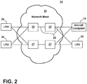
- FIG. 2 illustrates a non-limiting schematic view of an avionics data network 24, according to aspects of the disclosure.
- the avionics data network 24 can include, but is not limited to, a set of redundant network switching units, such as a first set of switching units 26 defining a first path and a second set of switching units 27 defining a second, or redundant, path.
- the first and second switching units 26, 27 collectively define a network mesh 28 for routing the transmission of data frames to and from the aircraft computer 18 and LRUs 20, via the transmission pathways 22.
- the network mesh 28 is further shown having a set of transmission pathways 22 between the network switching units 26 to provide redundancy in transmission pathways 22.
- the network mesh 28, the first set of switching units 26, the second set of switching units 27, or a combination thereof can be arranged, configured, or otherwise enabled to utilize a TSN based transmission schema.
- the aspects of the disclosure illustrated in FIG. 2 is merely one representation of the avionics data network 24, and alternative configurations, organization, and component quantities, including, but not limited to, aircraft computers 18, LRUs 20, or network switching units 26, are envisioned.
- FIG. 3 a simplified avionics data network 24 is illustrated, wherein a set of data-generating sources 30 are communicatively coupled with a set of data-consuming destinations 32, by way of a single network switching unit 26 via corresponding transmission pathways 22. Only a single network switching unit 26 is illustrated for ease of understanding, and it will be understood that any number of, or subset of the network switching units 26 of the avionics data network 24 can be further include or configured, as shown.
- the data-generating sources 30 or data-consuming destinations 32 can include any of the aforementioned aircraft computers 18 or LRUs 20, and are described herein as sources 30 or destinations 32 to provide a directional description of the data transmission. In this sense, each of the sources 30 or destinations 32 can be considered a networking end node.
- the network switching unit 26 can further comprise a switch core 34 having at least one ingress port 36, at least one egress port 38, switching logic 40, and a controller module 42.
- Each respective ingress port 36 can include an associated ingress memory buffer 37, and each respective egress port 38 can include an associated egress memory buffer 39 or egress port 38 queue.
- the memory size and capabilities of the respective buffers 37, 39 can vary, as desired.
- the network switching unit 26 can also include a legacy module 44 having an ingress port 41, an egress port 43, a processor or controller module 46, and memory 48.
- the legacy module 44 can be positioned, located, or disposed away from or apart from (e.g. removed from, or as a separate physical or virtual component) from the switch core 34. In this sense, the legacy module 44 can be separately configured, enabled, replaced, updated, or otherwise functionally adapted, relative to the switch core 34 or the network switching unit 26.
- the switch core 34 can be configured to couple with the set of data-generating sources 30 via the transmission pathways 22 received in respective ingress ports 36 of the switch core 34 and supply networking data, network communications, data frames, data packets, or the like (hereafter, "data frames"), generated by the sources 30 to the switch core 34.
- the switch core 34 can be configured to couple with the data-consuming sources 32 via the transmission pathways 22 received in the respective egress ports 38 of the core 34 and send data frames destined for the destinations 32 from the switching switch core 34.
- the data frames can include at least a portion of data defining the data-generating source 30 of the respective data frame, as well as the predetermined data-consuming destination or destinations 32 of the data frame.
- the switching core 34 provides a respective ingress or egress port 36, 38 for the data-generating source 30 or data-consuming destination 32, however alternative configurations are envisioned.
- a single ingress or egress port 36, 38 is configured to couple with a second network switching unit 26, and can thus carry data frames for any data-consuming destination 32 coupled with the second network switching unit 26.
- the switch core 34 includes an egress port 43 configured to connect with the ingress port 41 of the legacy module 44, and an ingress port 41 configured to connect with the egress port 43 of the legacy module 44.
- the switch core 34 can be in, for example, unidirectional communication with the data-generating sources 30 (i.e. only receiving data frames from the source 30) and data-consuming destinations 32 (i.e. only sending data frames to the destination 32), the switch core 34 and the legacy module 44 can be in bidirectional communication, sending and receiving, or exchanging data frames between the components 34, 44.
- a first set of transmission pathways 22 and ingress or egress ports 36, 38 of the switch core 34 can be defined by a particular pathway or communication schema utilized, for example, the A664p7 specification.
- the set of ingress ports 36 and set of egress ports 38 can include physical interfaces, such as Ethernet ports configured to operate at, for example, 10/100 or Gigabit per second (or faster) bandwidth speeds.
- the set of ingress and egress ports 36, 38 can be one or more antennas.
- a second set of transmission pathways 22 and ingress or egress ports 36, 38 of the switch core 34 can alternatively or additionally be defined by a different particular pathway or communication schema utilized, for example, a TSN schema.
- the network switching unit 26 can be configured or adapted to utilize the TSN schema, and thus, incorporating aspects of the disclosure to enable or otherwise facilitate legacy communications with otherwise incompatible transmission of data frames.
- the A664p7 communications or data frames generated by A664p7-compatible data-generating sources 30, or consumed by A664p7-compatible data-consuming destinations 32 can be communicated or transmitted via the TSN network switching unit 26 or the TSN switch core 34, by way of the incorporated legacy module 44, such as an A664p7 legacy module 44.
- transmission pathways 22 and ingress or egress ports 36, 38, 41, 43 are described herein, aspects of the disclosure are envisioned wherein the utilized pathways 22 or ports 36, 38 are compatible with, or compliant with the TSN specification or transmission schema, and adapted to carry or transmit A664p7 compatible communications or data frames, even when the A664p7 compatible communications or data frames are otherwise incompatible with the TSN specification to transmission schema.
- the switching logic 40 and the controller module 42 of the switch core 34 can operate together to route data frames of or through the switch core 34, as needed.
- the controller module 42 can further include a processor and suitable memory for including a portion of a computer program having an executable instruction set for controlling the operation of the controller module 42 or switching logic 40.
- the program can include a computer program product that can include machine-readable media for carrying or having machine-executable instructions or data structures stored thereon. Such machine-readable media can be any available media, which can be accessed by a general purpose or special purpose computer or other machine with a processor.
- Such a computer program can include routines, programs, objects, components, data structures, algorithms, etc. that have the technical effect of performing particular tasks or implement particular abstract data types.
- the one or more functions or routines of the controller module 42 can be converted to a computer program comprising a set of executable instructions, for execution by the controller or controller module 42.
- the controller module 42 can determine the predetermined data-consuming destination 32 for a data frame supplied to an ingress port 36 of the switch core 34, based at least partially on the data within the data frame. The controller module 42 can then command the switching logic 40 to route and forward the data frame to the egress port 38 (or an associated buffer 39 thereof) associated with the predetermined data-consuming destination 32 for delivery. In another instance, the controller module 42 can be configured to make a determination if a data frame received at an ingress port 36 is validated, verified, or authorized to arrive from the receiving ingress port 36.
- the controller module 42 can be configured to command the switching logic 40 to, for example, ignore or drop the data frame without forwarding the data frame on to a destination 32. In this sense, the controller module 42 can be configured to ensure only authorized data frames are transmitted through the avionics data network 24 or network switching unit 26.
- the controller module 42 can be configured to command the switching logic 40 to switch, direct, or forward the data frame traffic (or aspects representative of the same) received at the one or more ingress ports 36 to the egress port 43 connected with the legacy module 44, for example, by placing the received data frames in a sequential first-in, first-out (FIFO) queue to retain timing or ordering priority.
- the controller module 42 can then command the switching logic 40 to switch, direct, or forward the data frames (or aspects representative thereof) returned to the switch core 34 by the legacy module 44 to the egress port 38 or egress port buffer 39 associated with the predetermined data-consuming destination 32 for delivery.
- the legacy module 44 can be adapted or configured to determine whether the legacy A664p7 data frames received from legacy data-generating sources 30 can be delivered or communicated by the TSN schema based network switching unit 26 or switch core 34.
- the legacy module 44 can receive, or define a time-based allocation for delivering network traffic in accordance with the TSN schema.
- the time-based allocation for delivering network traffic can be at least partially based on allocated time slots for particular message delivery (e.g.
- specific data, or specific communications between at least one data-generating source 30 or data-consuming destination 32 is allocated a specific portion of time on the network to deliver related network traffic) or unallocated time slots (wherein no specific data or communications are allotted to the respective time slot for delivery).
- the allocated and unallocated time slots can be dynamically configured (e.g. at startup), manually configured, or defined by a component of the network, including but not limited to the network switching unit 26, the switch core 34, the legacy module 44, another networking component, or a combination thereof.
- the legacy module 44 can be configured to identify unallocated, or even under-utilized allocated time slots, and arrange, provide for, enable, or otherwise ensure the legacy A664p7 data frames are delivered by way of the TSN schema based network switching unit 26 or switch core 34 during those unallocated under-utilized allocated time slots.
- the legacy module 44 can receive at least a subset of incoming data frames received at the set of ingress ports 36 (or buffers 37 thereof), or aspects representative thereof, to identify A664p7 legacy data frames received by the network switching unit 26 or network core 34.
- the legacy module 44 can facilitate the legacy A664p7 data frame delivery by commanding, instruction, controllably delivering, or otherwise selectively scheduling the delivery of at least a subset of the data frames by way of the switching logic 40 or controller module 42 of the switch core 34.
- the legacy module 44 can facilitate or prepare for the delivery, if for example, the selectively scheduled delivery is during a future time period, by arranging or enabling the A664p7 data frames to be copied into the egress buffer 39.
- the switch core 34 or the network switching unit 26 can operably deliver the legacy A664p7 data frames from the egress port(s) 38 to another A664p7 based networking end node, such as one or more of the set of data-consuming destinations 32.
- aspects of the disclosure can be included wherein the legacy module 44 can be further configured to determine or ensure a respective A664p7 legacy data frame can be completely delivered (e.g. fully, without truncating) during the selected delivery time slot. For instance, if a set of data frames have been queued (e.g. in the egress buffer 39), a subset of data frames may not be deliverable based on the time slot.
- the legacy module 44 or the switch core 34 can be configured to estimate, predict, determine, or otherwise allocate a set of data frames that are sure to be delivered in the selected time slot, and either hold, retain, buffer, exclude, or drop data frames that are determined to be not deliverable or not completely deliverable during the selected time slot.
- the delivery of the A664p7 legacy data frames can be based on a first-in, first-out (FIFO) arrangement.
- aspects of the disclosure can enable or allow for the delivery of at least a subset of legacy A664p7 data frames by way of a TSN based network schema, whereby the legacy module 44 operations are configured to render the otherwise incompatible A664p7 data frames compliant with the TSN schema.
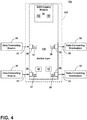
- FIG. 4 illustrates another avionics data network 124 according to another aspect of the present disclosure.
- the avionics data network 124 is similar to the avionics data network 24; therefore, like parts will be identified with like numerals increased by 100, with it being understood that the description of the like parts of the avionics data network 24 applies to the avionics data network 124, unless otherwise noted.
- the legacy module 44 of the network switching unit 126 is incorporated (e.g. as software or hardware) as a portion of the switch core 134.
- the operation of the legacy module 44, the network switching unit 126, the switch core 134, or a combination thereof can operate or perform as described, but without the legacy module 44 being apart from the network switching unit 126 or the switch core 134.
- FIG. 5 illustrates another avionics data network 224 according to another aspect of the present disclosure.
- the avionics data network 224 is similar to the avionics data network 24, 124; therefore, like parts will be identified with like numerals increased by 200, with it being understood that the description of the like parts of the avionics data network 24, 124 applies to the avionics data network 224, unless otherwise noted.
- the avionics data network 224 can include a master time signal 250 that is provided to at least a subset of the following components: the data-generating sources 230, the data-consuming destinations 232, or the network switching unit 226.
- the subset of components 226, 230, 232 can receive a time synchronization value (e.g. a "master time”) from the master time signal 250 for at least partial synchronization of operations.
- a time synchronization value e.g. a "master time
- At least a subset of the data-generating sources 30 can be configured or adapted to transmit, send, or provide legacy A664p7 data frames during a predetermined schedule, managed or regulated by the time synchronization value.
- the subset of the data-generating sources 230 can be configured or adapted to store locally (e.g. at the data-generating source 230, for instance in a buffer, not shown), and to send the locally stored legacy A664p7 data frames during the predetermined schedule.
- FIG. 6 illustrates another avionics data network 324 according to another aspect of the present disclosure.
- the avionics data network 324 is similar to the avionics data network 24, 124, 224; therefore, like parts will be identified with like numerals increased by 300, with it being understood that the description of the like parts of the avionics data network 24, 124, 224 applies to the avionics data network 324, unless otherwise noted.
- One difference is that the data-consuming destinations 332 or the network switching unit 324 can be configured or adapted to enable the splitting or separation of a single legacy data frame into a set of data frames or messages to be reassembled at a later time or at a downstream destination.
- aspects of the disclosure can be included wherein the legacy module 44 can be further configured to determine or ensure a respective A664p7 legacy data frame can be completely delivered (e.g. fully, without truncating) during the selected delivery time slot.
- aspects of the disclosure including FIG. 6 can be adapted or configured to determine whether a respective A664p7 legacy data frame can be completely delivered during the selected delivery time slot, and if not, to separate the respective A664p7 legacy data frame into a first A664p7 networking message and a second A664p7 networking message.
- the first A664p7 networking message can be scheduled for delivery, while the second A664p7 networking message can be further scheduled during the next unallocated or available time slot.
- the data-consuming destination 332 can further include a reassembly module 360 that can be adapted or configured to receive each of the first and second A664p7 networking messages, and reassemble them to the original A664p7 legacy data frame.
- a reassembly module 360 can be adapted or configured to receive each of the first and second A664p7 networking messages, and reassemble them to the original A664p7 legacy data frame.
- FIG. 7 illustrates a flow chart demonstrating a method 400 of operating a network architecture 24.
- the method 400 begins by receiving, at a set of data ingress ports 36 for a network switch core 34 certified for time-sensitive networking (TSN) schema network, a set of data frames from an A664p7 schema end node 30 of the network 24, at 410.
- the method 400 includes determining, by an A664p7 legacy module 44, a next available unallocated time slot of the TSN schema network, at 420.
- the method 400 continues by selectively scheduling, by the A664p7 legacy module 44, the set of data frames for the determined next available unallocated time slot, at 430.
- the method 400 proceeds to delivering, by the switch core 34, the set of data frames, without modification of the set of data frames, to another A664p7 schema end node 32 of the network during the determined next available unallocated time slot, at 440.
- the A664p7 legacy module 44 operations are configured to render the A664p7 communications compliant with the TSN schema.
- the method 400 can further include determining, by the A664p7 legacy module 44 or the switch core 34, whether at least a subset of the data frames can be completely delivered during the next available unallocated time slot, or delivering the set of data frames further includes delivering the subset of the data frames determined to be completely delivered during the next available unallocated time slot.
- the aspects disclosed herein provide an avionics data network for receiving and delivering a set of data frames.
- the technical effect is that the above described aspects enable the delivery of legacy A664p7 data frame in a TSN based network by way of the legacy module 44 enabling the delivery of the data frames during underutilized or unallocated time slots.
- different, otherwise non-compatible network schemas can effectively coexist on a single network.
- One advantage that can be realized in the above aspects is that the above described aspects will permit the use of legacy A664p7 equipment to be used along with equipment that supports the newer TSN protocol.
- Another advantage can include providing a deterministic Ethernet solution to aircraft customers, allowing, enabling, or otherwise accelerating the transition from several older network schemas to a new network schema.
Landscapes
- Engineering & Computer Science (AREA)
- Signal Processing (AREA)
- Computer Networks & Wireless Communication (AREA)
- Health & Medical Sciences (AREA)
- Computing Systems (AREA)
- General Health & Medical Sciences (AREA)
- Medical Informatics (AREA)
- Automation & Control Theory (AREA)
- Aviation & Aerospace Engineering (AREA)
- Small-Scale Networks (AREA)
- Data Exchanges In Wide-Area Networks (AREA)
Abstract
Description
- The disclosure relates to a method and apparatus for operating an avionics data network and more specifically to operating a network switch core.
- For contemporary aircraft, an avionics 'platform' consists of a variety of elements such as sensors, data concentrators, a data communications network, radio frequency sensors and communication equipment, computational elements, effectors, and graphical displays. These components must share information with other components over the data communications network.
- Legacy incarnations of these platform elements are in the form of individual subsystem elements often referred to as "federated systems". A federated system is an application-specific subsystem in a self-contained package having its own dedicated logic, processors, and input/output interfaces. Multiple and separated federated systems rely on common subsets of data sources, but lack the sharing of processing resources and interfaces among federated systems. A set of federated systems can be communicatively interconnected by utilizing separate data buses or a shared data network.
- Network components utilized to construct the data network can utilize a specialized data protocol, including relays, switches, communicative connections, and the like, to ensure performance of the network architecture for the specialized data, as for example, under the performance of the network communications defined by the ARINC 664 part 7 specification.
- In one aspect, aspects of the disclosure relate to an avionics data network including a network switch core configured for a time-sensitive networking (TSN) schema, a set of ARINC networking end nodes communicatively connected with the network switch core, and an ARINC legacy module connected with the network switch core and configured to receive a set of ARINC networking data from the set of ARINC networking end nodes, determine an available unallocated time slot of the TSN schema, and selectively scheduling the delivery of the set of ARINC networking data from the network switch core to another ARINC networking end node during the available unallocated time slot.
- In another aspect, aspects of the disclosure relate to a method of operating a network architecture, including receiving, at a set of data ingress ports for a network switch core certified for time-sensitive networking (TSN) schema network, a set of data frames from an ARINC schema end node of the network, determining, by an ARINC legacy module, a next available unallocated time slot of the TSN schema network, selectively scheduling, by the ARINC legacy module, the set of data frames for the determined next available unallocated time slot, and delivering, by the switch core, the set of data frames, without modification of the set of data frames, to another ARINC schema end node of the network during the determined next available unallocated time slot. The ARINC legacy module operations are configured to render the ARINC communications compliant with the TSN schema.
- In the drawings:
-
FIG. 1 is a top down schematic view of an example aircraft and avionics data network architecture of an aircraft, in accordance with various aspects described herein. -
FIG. 2 is a schematic view of an example avionics data network ofFIG. 1 , in accordance with various aspects described herein. -
FIG. 3 is a schematic view of a network switch of the avionics data network having a legacy module, in accordance with various aspects described herein. -
FIG. 4 is a schematic view of another network switch of the avionics data network having a legacy module, in accordance with various aspects described herein. -
FIG. 5 is a schematic view of a network switch of the avionics data network having a legacy module and a master time signal, in accordance with various aspects described herein. -
FIG. 6 is a schematic view of yet another network switch of the avionics data network having a legacy module, in accordance with various aspects described herein. -
FIG. 7 is a flow chart showing a method of operating the avionics data network, in accordance with various aspects described herein. - Aspects of the disclosure described herein are provided with respect to a specialized avionics data protocol, but it will be understood that the apparatus and method described herein can be implemented in any environment using a data communications network interconnecting a set of data-generating components with a set of data-consuming components. Aspects of the disclosure can include data communications networks configured to operate according to defined network characteristics or specifications. For example, contemporary aircraft operate a set of components interconnected by way of a data network defined by a network standard, such as the ARINC, or a subdivision thereof, for example, ARINC 664 part 7 ("A664p7") specification, incorporated herein in its entirety. The A664p7 specification defines compliant network operations including, but not limited to, redundancy, dedicated bandwidth, deterministic quality of service, and network switching performance. While aspects of the disclosure are described with respect to the A664p7 specification or A664p7 data frames, transmissions, and the like, the disclosure can be applicable to any legacy data transmissions.
- Additional, updated or new network standards can be incorporated into contemporary aircraft in order to operate the set of interconnected components. In some instances, it is desirable to ensure the updated or new network standards are compatible with legacy systems, such as the A664p7 specification, or A664p7 data transmissions. One non-limiting example of updated or new network standards can include time-sensitive networking (TSN) based standards, specifications, or transmission schemas. A further non-limiting example of a TSN based standard can include network operations in accordance with the Institute of Electrical and Electronics Engineers (IEEE) 802.1 TSN schemas. Additional TSN schemas can be included.
- While "a set of' various elements will be described, it will be understood that "a set" can include any number of the respective elements, including only one element. Also as used herein, while sensors can be described as "sensing" or "measuring" a respective value, sensing or measuring can include determining a value indicative of or related to the respective value, rather than directly sensing or measuring the value itself. The sensed or measured values can further be provided to additional components. For instance, the value can be provided to a controller module or processor, and the controller module or processor can perform processing on the value to determine a representative value or an electrical characteristic representative of said value.
- All directional references (e.g., radial, axial, upper, lower, upward, downward, left, right, lateral, front, back, top, bottom, above, below, vertical, horizontal, clockwise, counterclockwise) are only used for identification purposes to aid the reader's understanding of the disclosure, and do not create limitations, particularly as to the position, orientation, or use thereof. Connection references (e.g., attached, coupled, connected, and joined) are to be construed broadly and can include intermediate members between a collection of elements and relative movement between elements unless otherwise indicated. As such, connection references do not necessarily infer that two elements are directly connected and in fixed relation to each other. In non-limiting examples, connections or disconnections can be selectively configured to provide, enable, disable, or the like, an electrical connection or communicative connection between respective elements.
- As used herein, a "system" or a "controller module" can include at least one processor and memory. Non-limiting examples of the memory can include Random Access Memory (RAM), Read-Only Memory (ROM), non-volatile memory (NVM, such as flash memory, or one or more different types of portable electronic memory, such as discs, DVDs, CD-ROMs, etc., or any suitable combination of these types of memory. The processor can be configured to run any suitable programs or executable instructions designed to carry out various methods, functionality, processing tasks, calculations, or the like, to enable or achieve the technical operations or operations described herein. The program can include a computer program product that can include machine-readable media for carrying or having machine-executable instructions or data structures stored thereon. Such machine-readable media can be any available media, which can be accessed by a general purpose or special purpose computer or other machine with a processor. Generally, such a computer program can include routines, programs, objects, components, data structures, algorithms, etc., that have the technical effect of performing particular tasks or implement particular abstract data types.
- The exemplary drawings are for purposes of illustration only and the dimensions, positions, order and relative sizes reflected in the drawings attached hereto can vary.
- As illustrated in
FIG. 1 , anaircraft 10 can include at least one propulsion engine, shown as aleft engine system 12 andright engine system 14. Theaircraft 10 can further include one ormore aircraft computers 18, including, but not limited to data storage or processing units, or functional systems such as the flight management system or autopilot system, and a set of fixed aircraft components, such as line-replaceable units (LRU) 20, networking end nodes, or modular components of a vehicle or aircraft. In the aircraft environment, the aircraft computers orLRUs 20 can be designed to operate according to a particular operation, interoperability, or form factor standards, such as those defined by ARINC series standards. In the exemplary aspects illustrated, theaircraft computers 18 can be positioned near the nose or cockpit of theaircraft 10 and theLRUs 20 can be positioned throughout theaircraft 10. Theaircraft computers 18 andLRUs 20 can be configured to be communicatively coupled by way of a series ofdata transmission pathways 22, network relays, or network switches 16. Thedata transmission pathways 22 can include a physical connection between therespective components aircraft computers 18,LRUs 20,pathways 22, and switches 16 can form an avionics data network for the aircraft. - The
LRUs 20 can include, for example, entirely contained systems, sensors, radios, or other auxiliary equipment to manage or operate aircraft functions. At least a set ofaircraft computers 18 orLRUs 20 can, for example, generate data, which can be modified, computed, or processed prior to, or in preparation for packaging the data into data frames to be transmitted over the avionics data network by way of thepathways 22 or switches 16. At least another set ofaircraft computers 18 orLRUs 20 can, for example, consume the data transmitted over the avionics data network. In some instances, asingle aircraft computer 18 orLRU 20 can operate to both generate and consume data. As used herein, "consume," "consuming," or "consumption" of data will be understood to include, but is not limited to, performing or executing a computer program, routine, calculation, or process on at least a portion of the data, storing the data in memory, or otherwise making use of at least a portion of the data. - The illustrated
aircraft 10 aspects is merely one non-limiting example of anaircraft 10 that can be used in aspects of the disclosure described herein. Particularities of the illustratedaircraft 10 aspects, including relative size, length, number of engines, type of engines, and location of various components are not germane to the aspects of the disclosure, unless otherwise noted. - In some example components, such as the
aircraft computers 18 or LRUs 20, the components can be removably fixed to the aircraft for maintenance, diagnostics, or repair purposes, but statically fixed during, for example, flight. Additionally, whileaircraft computers 18 and LRUs 20 are described, any data generating or data receiving or consuming components fixed relative to an aircraft can be included as aspects of the disclosure as fixed components. For example, systems such as a flight management system, primary flight display, cockpit display system, autopilot, or autoland systems can be considered fixed components, as used herein. -
FIG. 2 illustrates a non-limiting schematic view of anavionics data network 24, according to aspects of the disclosure. Theavionics data network 24 can include, but is not limited to, a set of redundant network switching units, such as a first set of switchingunits 26 defining a first path and a second set of switchingunits 27 defining a second, or redundant, path. The first andsecond switching units network mesh 28 for routing the transmission of data frames to and from theaircraft computer 18 andLRUs 20, via thetransmission pathways 22. Thenetwork mesh 28 is further shown having a set oftransmission pathways 22 between thenetwork switching units 26 to provide redundancy intransmission pathways 22. In one non-limiting example, thenetwork mesh 28, the first set of switchingunits 26, the second set of switchingunits 27, or a combination thereof, can be arranged, configured, or otherwise enabled to utilize a TSN based transmission schema. The aspects of the disclosure illustrated inFIG. 2 is merely one representation of theavionics data network 24, and alternative configurations, organization, and component quantities, including, but not limited to,aircraft computers 18,LRUs 20, ornetwork switching units 26, are envisioned. - Turning now to
FIG. 3 , a simplifiedavionics data network 24 is illustrated, wherein a set of data-generatingsources 30 are communicatively coupled with a set of data-consumingdestinations 32, by way of a singlenetwork switching unit 26 via correspondingtransmission pathways 22. Only a singlenetwork switching unit 26 is illustrated for ease of understanding, and it will be understood that any number of, or subset of thenetwork switching units 26 of theavionics data network 24 can be further include or configured, as shown. Moreover, as explained above, the data-generatingsources 30 or data-consumingdestinations 32 can include any of theaforementioned aircraft computers 18 orLRUs 20, and are described herein assources 30 ordestinations 32 to provide a directional description of the data transmission. In this sense, each of thesources 30 ordestinations 32 can be considered a networking end node. - The
network switching unit 26 can further comprise aswitch core 34 having at least one ingress port 36, at least oneegress port 38, switchinglogic 40, and acontroller module 42. Each respective ingress port 36 can include an associatedingress memory buffer 37, and eachrespective egress port 38 can include an associatedegress memory buffer 39 oregress port 38 queue. The memory size and capabilities of therespective buffers network switching unit 26 can also include alegacy module 44 having aningress port 41, anegress port 43, a processor orcontroller module 46, andmemory 48. In the non-limiting example illustrated, thelegacy module 44 can be positioned, located, or disposed away from or apart from (e.g. removed from, or as a separate physical or virtual component) from theswitch core 34. In this sense, thelegacy module 44 can be separately configured, enabled, replaced, updated, or otherwise functionally adapted, relative to theswitch core 34 or thenetwork switching unit 26. - The
switch core 34 can be configured to couple with the set of data-generatingsources 30 via thetransmission pathways 22 received in respective ingress ports 36 of theswitch core 34 and supply networking data, network communications, data frames, data packets, or the like (hereafter, "data frames"), generated by thesources 30 to theswitch core 34. Likewise, theswitch core 34 can be configured to couple with the data-consumingsources 32 via thetransmission pathways 22 received in therespective egress ports 38 of thecore 34 and send data frames destined for thedestinations 32 from the switchingswitch core 34. It is understood that the data frames can include at least a portion of data defining the data-generatingsource 30 of the respective data frame, as well as the predetermined data-consuming destination ordestinations 32 of the data frame. - As shown, the switching
core 34 provides a respective ingress oregress port 36, 38 for the data-generatingsource 30 or data-consumingdestination 32, however alternative configurations are envisioned. For example, one alternative configuration envisions a single ingress oregress port 36, 38 is configured to couple with a secondnetwork switching unit 26, and can thus carry data frames for any data-consumingdestination 32 coupled with the secondnetwork switching unit 26. In addition to theaforementioned switch core 34ports 36, 38, theswitch core 34 includes anegress port 43 configured to connect with theingress port 41 of thelegacy module 44, and aningress port 41 configured to connect with theegress port 43 of thelegacy module 44. In this sense, while theswitch core 34 can be in, for example, unidirectional communication with the data-generating sources 30 (i.e. only receiving data frames from the source 30) and data-consuming destinations 32 (i.e. only sending data frames to the destination 32), theswitch core 34 and thelegacy module 44 can be in bidirectional communication, sending and receiving, or exchanging data frames between thecomponents - A first set of
transmission pathways 22 and ingress oregress ports 36, 38 of theswitch core 34 can be defined by a particular pathway or communication schema utilized, for example, the A664p7 specification. For instance, when thetransmission pathway 22 is an Ethernet cord, the set of ingress ports 36 and set ofegress ports 38 can include physical interfaces, such as Ethernet ports configured to operate at, for example, 10/100 or Gigabit per second (or faster) bandwidth speeds. In another instance when thetransmission pathway 22 is a wireless transmission, the set of ingress andegress ports 36, 38 can be one or more antennas. A second set oftransmission pathways 22 and ingress oregress ports 36, 38 of theswitch core 34 can alternatively or additionally be defined by a different particular pathway or communication schema utilized, for example, a TSN schema. Furthermore, in yet another non-limiting example, thenetwork switching unit 26 can be configured or adapted to utilize the TSN schema, and thus, incorporating aspects of the disclosure to enable or otherwise facilitate legacy communications with otherwise incompatible transmission of data frames. In the non-limiting example described, the A664p7 communications or data frames generated by A664p7-compatible data-generatingsources 30, or consumed by A664p7-compatible data-consumingdestinations 32 can be communicated or transmitted via the TSNnetwork switching unit 26 or theTSN switch core 34, by way of the incorporatedlegacy module 44, such as anA664p7 legacy module 44. - While a number of
transmission pathways 22 and ingress oregress ports pathways 22 orports 36, 38 are compatible with, or compliant with the TSN specification or transmission schema, and adapted to carry or transmit A664p7 compatible communications or data frames, even when the A664p7 compatible communications or data frames are otherwise incompatible with the TSN specification to transmission schema. - The switching
logic 40 and thecontroller module 42 of theswitch core 34 can operate together to route data frames of or through theswitch core 34, as needed. For example, thecontroller module 42 can further include a processor and suitable memory for including a portion of a computer program having an executable instruction set for controlling the operation of thecontroller module 42 or switchinglogic 40. The program can include a computer program product that can include machine-readable media for carrying or having machine-executable instructions or data structures stored thereon. Such machine-readable media can be any available media, which can be accessed by a general purpose or special purpose computer or other machine with a processor. Generally, such a computer program can include routines, programs, objects, components, data structures, algorithms, etc. that have the technical effect of performing particular tasks or implement particular abstract data types. In implementation, the one or more functions or routines of thecontroller module 42 can be converted to a computer program comprising a set of executable instructions, for execution by the controller orcontroller module 42. - In one instance, the
controller module 42 can determine the predetermined data-consumingdestination 32 for a data frame supplied to an ingress port 36 of theswitch core 34, based at least partially on the data within the data frame. Thecontroller module 42 can then command the switchinglogic 40 to route and forward the data frame to the egress port 38 (or an associatedbuffer 39 thereof) associated with the predetermined data-consumingdestination 32 for delivery. In another instance, thecontroller module 42 can be configured to make a determination if a data frame received at an ingress port 36 is validated, verified, or authorized to arrive from the receiving ingress port 36. When an arriving data frame is received at an invalid, unverified, or unauthorized receiving ingress port 36, thecontroller module 42 can be configured to command the switchinglogic 40 to, for example, ignore or drop the data frame without forwarding the data frame on to adestination 32. In this sense, thecontroller module 42 can be configured to ensure only authorized data frames are transmitted through theavionics data network 24 ornetwork switching unit 26. - In yet another instance, the
controller module 42 can be configured to command the switchinglogic 40 to switch, direct, or forward the data frame traffic (or aspects representative of the same) received at the one or more ingress ports 36 to theegress port 43 connected with thelegacy module 44, for example, by placing the received data frames in a sequential first-in, first-out (FIFO) queue to retain timing or ordering priority. Thecontroller module 42 can then command the switchinglogic 40 to switch, direct, or forward the data frames (or aspects representative thereof) returned to theswitch core 34 by thelegacy module 44 to theegress port 38 oregress port buffer 39 associated with the predetermined data-consumingdestination 32 for delivery. - In another non-limiting instance, the
legacy module 44, orcontroller module 46 thereof, can be adapted or configured to determine whether the legacy A664p7 data frames received from legacy data-generatingsources 30 can be delivered or communicated by the TSN schema basednetwork switching unit 26 orswitch core 34. In this sense, and in accordance with the TSN schema, thelegacy module 44 can receive, or define a time-based allocation for delivering network traffic in accordance with the TSN schema. Also in accordance with a TSN schema, the time-based allocation for delivering network traffic can be at least partially based on allocated time slots for particular message delivery (e.g. specific data, or specific communications between at least one data-generatingsource 30 or data-consumingdestination 32 is allocated a specific portion of time on the network to deliver related network traffic) or unallocated time slots (wherein no specific data or communications are allotted to the respective time slot for delivery). In non-limiting examples, the allocated and unallocated time slots can be dynamically configured (e.g. at startup), manually configured, or defined by a component of the network, including but not limited to thenetwork switching unit 26, theswitch core 34, thelegacy module 44, another networking component, or a combination thereof. - For instance, the
legacy module 44 can be configured to identify unallocated, or even under-utilized allocated time slots, and arrange, provide for, enable, or otherwise ensure the legacy A664p7 data frames are delivered by way of the TSN schema basednetwork switching unit 26 orswitch core 34 during those unallocated under-utilized allocated time slots. In another non-limiting example, thelegacy module 44 can receive at least a subset of incoming data frames received at the set of ingress ports 36 (or buffers 37 thereof), or aspects representative thereof, to identify A664p7 legacy data frames received by thenetwork switching unit 26 ornetwork core 34. - In another non-limiting example, the
legacy module 44 can facilitate the legacy A664p7 data frame delivery by commanding, instruction, controllably delivering, or otherwise selectively scheduling the delivery of at least a subset of the data frames by way of the switchinglogic 40 orcontroller module 42 of theswitch core 34. In yet another non-limiting example, thelegacy module 44 can facilitate or prepare for the delivery, if for example, the selectively scheduled delivery is during a future time period, by arranging or enabling the A664p7 data frames to be copied into theegress buffer 39. - Upon reaching the selectively scheduled time slot, the
switch core 34 or thenetwork switching unit 26 can operably deliver the legacy A664p7 data frames from the egress port(s) 38 to another A664p7 based networking end node, such as one or more of the set of data-consumingdestinations 32. - In another non-limiting example, aspects of the disclosure can be included wherein the
legacy module 44 can be further configured to determine or ensure a respective A664p7 legacy data frame can be completely delivered (e.g. fully, without truncating) during the selected delivery time slot. For instance, if a set of data frames have been queued (e.g. in the egress buffer 39), a subset of data frames may not be deliverable based on the time slot. Thelegacy module 44 or theswitch core 34 can be configured to estimate, predict, determine, or otherwise allocate a set of data frames that are sure to be delivered in the selected time slot, and either hold, retain, buffer, exclude, or drop data frames that are determined to be not deliverable or not completely deliverable during the selected time slot. In one non-limiting example, the delivery of the A664p7 legacy data frames can be based on a first-in, first-out (FIFO) arrangement. - In this sense, aspects of the disclosure can enable or allow for the delivery of at least a subset of legacy A664p7 data frames by way of a TSN based network schema, whereby the
legacy module 44 operations are configured to render the otherwise incompatible A664p7 data frames compliant with the TSN schema. -
FIG. 4 illustrates anotheravionics data network 124 according to another aspect of the present disclosure. Theavionics data network 124 is similar to theavionics data network 24; therefore, like parts will be identified with like numerals increased by 100, with it being understood that the description of the like parts of theavionics data network 24 applies to theavionics data network 124, unless otherwise noted. One difference is that thelegacy module 44 of thenetwork switching unit 126 is incorporated (e.g. as software or hardware) as a portion of theswitch core 134. In this non-limiting example, the operation of thelegacy module 44, thenetwork switching unit 126, theswitch core 134, or a combination thereof, can operate or perform as described, but without thelegacy module 44 being apart from thenetwork switching unit 126 or theswitch core 134. -
FIG. 5 illustrates anotheravionics data network 224 according to another aspect of the present disclosure. Theavionics data network 224 is similar to theavionics data network avionics data network avionics data network 224, unless otherwise noted. One difference is that theavionics data network 224 can include amaster time signal 250 that is provided to at least a subset of the following components: the data-generatingsources 230, the data-consumingdestinations 232, or thenetwork switching unit 226. In this sense, the subset ofcomponents master time signal 250 for at least partial synchronization of operations. - In one non-limiting example, at least a subset of the data-generating
sources 30 can be configured or adapted to transmit, send, or provide legacy A664p7 data frames during a predetermined schedule, managed or regulated by the time synchronization value. In another non-limiting example, the subset of the data-generatingsources 230 can be configured or adapted to store locally (e.g. at the data-generatingsource 230, for instance in a buffer, not shown), and to send the locally stored legacy A664p7 data frames during the predetermined schedule. -
FIG. 6 illustrates anotheravionics data network 324 according to another aspect of the present disclosure. Theavionics data network 324 is similar to theavionics data network avionics data network avionics data network 324, unless otherwise noted. One difference is that the data-consumingdestinations 332 or thenetwork switching unit 324 can be configured or adapted to enable the splitting or separation of a single legacy data frame into a set of data frames or messages to be reassembled at a later time or at a downstream destination. - For example, as described with reference to
FIG. 3 , aspects of the disclosure can be included wherein thelegacy module 44 can be further configured to determine or ensure a respective A664p7 legacy data frame can be completely delivered (e.g. fully, without truncating) during the selected delivery time slot. Aspects of the disclosure includingFIG. 6 can be adapted or configured to determine whether a respective A664p7 legacy data frame can be completely delivered during the selected delivery time slot, and if not, to separate the respective A664p7 legacy data frame into a first A664p7 networking message and a second A664p7 networking message. In this example, the first A664p7 networking message can be scheduled for delivery, while the second A664p7 networking message can be further scheduled during the next unallocated or available time slot. - The data-consuming
destination 332 can further include areassembly module 360 that can be adapted or configured to receive each of the first and second A664p7 networking messages, and reassemble them to the original A664p7 legacy data frame. -
FIG. 7 illustrates a flow chart demonstrating amethod 400 of operating anetwork architecture 24. Themethod 400 begins by receiving, at a set of data ingress ports 36 for anetwork switch core 34 certified for time-sensitive networking (TSN) schema network, a set of data frames from an A664p7schema end node 30 of thenetwork 24, at 410. Next, themethod 400 includes determining, by anA664p7 legacy module 44, a next available unallocated time slot of the TSN schema network, at 420. Themethod 400 continues by selectively scheduling, by theA664p7 legacy module 44, the set of data frames for the determined next available unallocated time slot, at 430. Then, themethod 400 proceeds to delivering, by theswitch core 34, the set of data frames, without modification of the set of data frames, to another A664p7schema end node 32 of the network during the determined next available unallocated time slot, at 440. TheA664p7 legacy module 44 operations are configured to render the A664p7 communications compliant with the TSN schema. - The sequence depicted is for illustrative purposes only and is not meant to limit the
method 400 in any way as it is understood that the portions of the method can proceed in a different logical order, additional or intervening portions can be included, or described portions of the method can be divided into multiple portions, or described portions of the method can be omitted without detracting from the described method. For example, themethod 400 can further include determining, by theA664p7 legacy module 44 or theswitch core 34, whether at least a subset of the data frames can be completely delivered during the next available unallocated time slot, or delivering the set of data frames further includes delivering the subset of the data frames determined to be completely delivered during the next available unallocated time slot. - Many other possible aspects and configurations in addition to that shown in the above figures are contemplated by the present disclosure.
- The aspects disclosed herein provide an avionics data network for receiving and delivering a set of data frames. The technical effect is that the above described aspects enable the delivery of legacy A664p7 data frame in a TSN based network by way of the
legacy module 44 enabling the delivery of the data frames during underutilized or unallocated time slots. In this sense, different, otherwise non-compatible network schemas can effectively coexist on a single network. One advantage that can be realized in the above aspects is that the above described aspects will permit the use of legacy A664p7 equipment to be used along with equipment that supports the newer TSN protocol. Another advantage can include providing a deterministic Ethernet solution to aircraft customers, allowing, enabling, or otherwise accelerating the transition from several older network schemas to a new network schema. - To the extent not already described, the different features and structures of the various aspects can be used in combination with others as desired. That one feature cannot be illustrated in the aspects is not meant to be construed that it cannot be, but is done for brevity of description. Thus, the various features of the different aspects can be mixed and matched as desired to form new aspects, whether or not the new aspects are expressly described. All combinations or permutations of features described herein are covered by this disclosure.
- Further aspects of the invention are provided by the subject matter of the following clauses:
- 1. An avionics data network including a network switch core configured for a time-sensitive networking (TSN) schema, a set of ARINC 664 part 7 (A664p7) networking end nodes communicatively connected with the network switch core, and an A664p7 legacy module connected with the network switch core and configured to receive a set of A664p7 networking data from the set of A664p7 networking end nodes, determine an available unallocated time slot of the TSN schema, and selectively scheduling the delivery of the set of A664p7 networking data from the network switch core to another A664p7 networking end node during the available unallocated time slot.
- 2. The avionics data network of any preceding clause wherein the set of A664p7 networking end nodes are otherwise incompatible with the TSN schema.
- 3. The avionics data network of any preceding clause wherein the TSN schema is in accordance with Institute of Electrical and Electronics Engineers (IEEE) 802.1 TSN schemas.
- 4. The avionics data network of any preceding clause wherein at least a subset of the A664p7 networking end nodes further receives a time synchronization value.
- 5. The avionics data network of any preceding clause wherein the subset of the A664p7 networking end nodes are configured to send A664p7 networking data, received by the A664p7 legacy module, during a predetermined schedule.
- 6. The avionics data network of any preceding clause wherein the subset of A664p7 networking end nodes generate A664p7 networking data asynchronously, and locally store the generated A664p7 networking data until sending during the predetermined schedule.
- 7. The avionics data network of any preceding clause wherein the A664p7 legacy module is apart from the network switch core.
- 8. The avionics data network of any preceding clause wherein the A664p7 legacy module is further configured to determine whether at least a subset of the A664p7 networking data can be completely delivered during the available unallocated time slot.
- 9. The avionics data network of any preceding clause wherein the A664p7 legacy module is further configured to selectively schedule the delivery of the subset of the A664p7 networking data upon determining the subset of the A664p7 networking data can be completely delivered during the available unallocated time slot.
- 10. The avionics data network of any preceding clause wherein the A664p7 legacy module is further configured to divide the subset of the A664p7 networking data into at least a first A664p7 networking message and a second A664p7 networking message upon determining the subset of the A664p7 networking data cannot be completely delivered during the available unallocated time slot, and further configured to selectively schedule the delivery of the first A664p7 networking message.
- 11. The avionics data network of any preceding clause wherein the A664p7 legacy module is further configured to selectively schedule the delivery of the second A664p7 networking message during another unallocated time slot.
- 12. The avionics data network of any preceding clause wherein the another A664p7 networking end node is configured to reassemble the first and second A664p7 network messages.
- 13. The avionics data network of any preceding clause wherein the network switch core includes an egress port queue, and wherein selectively scheduling the delivery of the set of A664p7 networking data from the network switch core to another A664p7 networking end node includes queuing the set of A664p7 networking data in the egress port queue.
- 14. An avionics data network including a network switch core configured for a time-sensitive networking (TSN) schema and defining a set of allocated and unallocated time slots for delivering data by way of the network switch core, a set of ARINC 664 part 7 (A664p7) networking end nodes communicatively connected with the network switch core, and an A664p7 legacy module having a controller module configured to identify incoming A664p7 communications from the set of A664p7 networking end nodes, determine the next available unallocated time slot of the TSN schema, controllably deliver at least a subset of the identified incoming A664p7 communications to at least another subset of the A664p7 networking end nodes by way of the TSN schema and network switch core, wherein the A664p7 legacy module operations are configured to render the A664p7 communications compliant with the TSN schema.
- 15. The avionics data network of any preceding clause wherein the A664p7 legacy module is apart from the network switch core.
- 16. The avionics data network of any preceding clause wherein the A664p7 legacy module is further configured to determine whether at least a subset of the A664p7 communications can be completely delivered during the next available unallocated time slot.
- 17. The avionics data network of any preceding clause wherein the A664p7 legacy module is further configured to controllably deliver of the subset of the A664p7 communications upon determining the subset of the A664p7 communications can be completely delivered during the next available unallocated time slot.
- 18. A method of operating a network architecture including receiving, at a set of data ingress ports for a network switch core certified for time-sensitive networking (TSN) schema network, a set of data frames from an ARINC 664 part 7 (A664p7) schema end node of the network, determining, by an A664p7 legacy module, a next available unallocated time slot of the TSN schema network, selectively scheduling, by the A664p7 legacy module, the set of data frames for the determined next available unallocated time slot, and delivering, by the switch core, the set of data frames, without modification of the set of data frames, to another A664p7 schema end node of the network during the determined next available unallocated time slot, wherein the A664p7 legacy module operations are configured to render the A664p7 communications compliant with the TSN schema.
- 19. The method of any preceding clause, further comprising determining, by the A664p7 legacy module, whether at least a subset of the data frames can be completely delivered during the next available unallocated time slot.
- 20. The method of any preceding clause wherein the delivering the set of data frames includes delivering the subset of the data frames determined to be completely delivered during the next available unallocated time slot.
- This written description uses examples to disclose aspects of the disclosure, including the best mode, and also to enable any person skilled in the art to practice the disclosure, including making and using any devices or systems and performing any incorporated methods. The patentable scope of the disclosure is defined by the claims, and can include other examples that occur to those skilled in the art. Such other examples are intended to be within the scope of the claims if they have structural elements that do not differ from the literal language of the claims, or if they include equivalent structural elements with insubstantial differences from the literal languages of the claims.
Claims (15)
- An avionics data network (24, 124, 224, 324) comprising:a network switch core (34, 134) configured for a time-sensitive networking, TSN, schema;a set of ARINC 664 part 7, A664p7, networking end nodes (30, 32, 230, 232, 332) communicatively connected with the network switch core (34, 134); andan A664p7 legacy module (44) connected with the network switch core (34, 134) and configured to receive a set of A664p7 networking data from the set of A664p7 networking end nodes (30, 230), determine an available unallocated time slot of the TSN schema, and selectively scheduling the delivery of the set of A664p7 networking data from the network switch core (34, 134) to another A664p7 networking end node (32, 232, 332) during the available unallocated time slot.
- The avionics data network (24, 124, 224, 324) of claim 1 wherein the set of A664p7 networking end nodes (30, 32, 230, 232, 332) are otherwise incompatible with the TSN schema.
- The avionics data network (24, 124, 224, 324) of claim 1 or 2 wherein the TSN schema is in accordance with Institute of Electrical and Electronics Engineers (IEEE) 802.1 TSN schemas.
- The avionics data network (24, 124, 224, 324) of any of claims 1 to 3 wherein at least a subset of the A664p7 networking end nodes (30, 32, 230, 232, 332) further receives a time synchronization value.
- The avionics data network (24, 124, 224, 324) of claim 4 wherein the subset of the A664p7 networking end nodes (230) are configured to send A664p7 networking data, received by the A664p7 legacy module (44), during a predetermined schedule.
- The avionics data network (24, 124, 224, 324) of claim 5 wherein the subset of A664p7 networking end nodes (30, 230) generate A664p7 networking data asynchronously, and locally store the generated A664p7 networking data until sending during the predetermined schedule.
- The avionics data network (24, 124, 224, 324) of any of claims 1 to 6, wherein the A664p7 legacy module (44) is apart from the network switch core (34).
- The avionics data network (24, 124, 224, 324) of any of claims 1 to 7, wherein the A664p7 legacy module (44) is further configured to determine whether at least a subset of the A664p7 networking data can be completely delivered during the available unallocated time slot.
- The avionics data network (24, 124, 224, 324) of claim 8 wherein the A664p7 legacy module (44) is further configured to selectively schedule the delivery of the subset of the A664p7 networking data upon determining the subset of the A664p7 networking data can be completely delivered during the available unallocated time slot.
- The avionics data network (24, 124, 224, 324) of claim 8 or 9, wherein the A664p7 legacy module (44) is further configured to divide the subset of the A664p7 networking data into at least a first A664p7 networking message and a second A664p7 networking message upon determining the subset of the A664p7 networking data cannot be completely delivered during the available unallocated time slot, and further configured to selectively schedule the delivery of the first A664p7 networking message.
- The avionics data network (24, 124, 224, 324) of claim 10 wherein the A664p7 legacy module (44) is further configured to selectively schedule the delivery of the second A664p7 networking message during another unallocated time slot.
- The avionics data network (24, 124, 224, 324) of claim 10 or 11 wherein the A664p7 legacy module (44) is further configured to selectively schedule the delivery of the second A664p7 networking message during another unallocated time slot and wherein the another A664p7 networking end node (332) is configured to reassemble the first and second A664p7 network messages.
- A method of operating a network architecture (24, 124, 224, 324) comprising:receiving, at a set of data ingress ports (36) for a network switch core (34, 134) certified for time-sensitive networking, TSN, schema network, a set of data frames from an ARINC 664 part 7, A664p7, schema end node (30, 230) of the network;determining, by an A664p7 legacy module (44), a next available unallocated time slot of the TSN schema network;selectively scheduling, by the A664p7 legacy module (44), the set of data frames for the determined next available unallocated time slot; anddelivering, by the switch core (34, 134), the set of data frames, without modification of the set of data frames, to another A664p7 schema end node (32, 232, 332) of the network during the determined next available unallocated time slot;wherein the A664p7 legacy module (44) operations are configured to render the A664p7 communications compliant with the TSN schema.
- The method of claim 13, further comprising determining, by the A664p7 legacy module (44), whether at least a subset of the data frames can be completely delivered during the next available unallocated time slot.
- The method of claim 14 wherein the delivering the set of data frames includes delivering the subset of the data frames determined to be completely delivered during the next available unallocated time slot.
Applications Claiming Priority (1)
| Application Number | Priority Date | Filing Date | Title |
|---|---|---|---|
| US16/131,526 US10270567B1 (en) | 2018-09-14 | 2018-09-14 | Avionics data networks |
Publications (2)
| Publication Number | Publication Date |
|---|---|
| EP3624419A1 true EP3624419A1 (en) | 2020-03-18 |
| EP3624419B1 EP3624419B1 (en) | 2021-10-27 |
Family
ID=66174808
Family Applications (1)
| Application Number | Title | Priority Date | Filing Date |
|---|---|---|---|
| EP19197297.5A Active EP3624419B1 (en) | 2018-09-14 | 2019-09-13 | Avionics data network |
Country Status (3)
| Country | Link |
|---|---|
| US (1) | US10270567B1 (en) |
| EP (1) | EP3624419B1 (en) |
| CN (1) | CN110912667B (en) |
Cited By (3)
| Publication number | Priority date | Publication date | Assignee | Title |
|---|---|---|---|---|
| EP3989514A1 (en) * | 2020-10-26 | 2022-04-27 | GE Aviation Systems LLC | Converged avionics data network |
| EP4239959A1 (en) * | 2022-03-01 | 2023-09-06 | GE Aviation Systems LLC | Converged avionics data network |
| DE112021005765B4 (en) | 2021-04-26 | 2024-10-10 | Mitsubishi Electric Corporation | communication device, communication method and program |
Families Citing this family (7)
| Publication number | Priority date | Publication date | Assignee | Title |
|---|---|---|---|---|
| US10979368B2 (en) * | 2017-08-02 | 2021-04-13 | Nebbiolo Technologies, Inc. | Architecture for converged industrial control and real time applications |
| US11516078B2 (en) | 2019-09-30 | 2022-11-29 | Samsung Electronics Co., Ltd. | Apparatus and method for supporting TSC |
| DE102019215058A1 (en) * | 2019-09-30 | 2021-04-01 | Airbus Operations Gmbh | AVIONICS NETWORK WITH SYNCHRONIZATION DOMAINS AND METHODS FOR SYNCHRONIZING NETWORK PARTICIPANTS IN AN AVIONICS NETWORK |
| US11284365B2 (en) * | 2019-10-25 | 2022-03-22 | Rockwell Collins, Inc. | Time synchronization over redundant and deterministic switch-based avionics networks |
| US11558256B2 (en) * | 2019-10-28 | 2023-01-17 | Ge Aviation Systems Llc | Method and system for automatic configuration of a communications interface for a specialized data network of an aircraft |
| US11411891B2 (en) | 2020-10-30 | 2022-08-09 | Ge Aviation Systems Llc | System and method for a time-sensitive network |
| CN114301564B (en) * | 2021-12-28 | 2024-08-20 | 北京和利时系统工程有限公司 | TSN node, time certainty method, device and medium of node |
Citations (1)
| Publication number | Priority date | Publication date | Assignee | Title |
|---|---|---|---|---|
| US20180084055A1 (en) * | 2016-09-19 | 2018-03-22 | General Electric Company | Vehicle control system |
Family Cites Families (15)
| Publication number | Priority date | Publication date | Assignee | Title |
|---|---|---|---|---|
| DE19954377C2 (en) | 1999-11-12 | 2003-04-17 | Airbus Gmbh | Data transmission system for aircraft |
| FR2832011B1 (en) | 2001-11-05 | 2005-05-20 | Airbus France | COMMUTED FULL DUPLEX ETHERNET TYPE COMMUNICATION NETWORK AND METHOD FOR IMPLEMENTING THE SAME |
| US7756145B2 (en) * | 2005-12-02 | 2010-07-13 | The Boeing Company | Methods and apparatus providing an airborne e-enabled architecture as a system of systems |
| US8315274B2 (en) * | 2006-03-29 | 2012-11-20 | Honeywell International Inc. | System and method for supporting synchronous system communications and operations |
| US8451860B2 (en) | 2007-02-08 | 2013-05-28 | The Boeing Company | Low-weight hybrid deterministic highspeed data bus |
| US7933202B2 (en) * | 2009-02-03 | 2011-04-26 | Honeywell International Inc. | Bounded minimal latency for network resources without synchronization |
| US20130208630A1 (en) * | 2012-02-15 | 2013-08-15 | Ge Aviation Systems Llc | Avionics full-duplex switched ethernet network |
| US9485113B2 (en) * | 2013-10-11 | 2016-11-01 | Ge Aviation Systems Llc | Data communications network for an aircraft |
| US9749256B2 (en) * | 2013-10-11 | 2017-08-29 | Ge Aviation Systems Llc | Data communications network for an aircraft |
| US10164793B2 (en) * | 2013-10-15 | 2018-12-25 | National Instruments Corporation | System and method for interoperability between multiple networks |
| GB2532773A (en) | 2014-11-27 | 2016-06-01 | Airbus Operations Sas | Improvements in or relating to avionics networks |
| EP3057273B1 (en) * | 2015-02-13 | 2019-03-27 | Mitsubishi Electric R&D Centre Europe B.V. | Method for a traffic shaping in a network |
| US9769082B2 (en) | 2015-04-01 | 2017-09-19 | Honeywell International Inc. | System and method for network bandwidth, buffers and timing management using hybrid scheduling of traffic with different priorities and guarantees |
| US9762509B2 (en) | 2015-04-20 | 2017-09-12 | Ge Aviation Systems Llc | Apparatus and method of operating a network traffic policing module |
| US10205784B2 (en) | 2016-03-21 | 2019-02-12 | General Electric Company | Communication system and method for controlling data distribution quality of service in time sensitive networks |
-
2018
- 2018-09-14 US US16/131,526 patent/US10270567B1/en active Active
-
2019
- 2019-09-06 CN CN201910842259.3A patent/CN110912667B/en active Active
- 2019-09-13 EP EP19197297.5A patent/EP3624419B1/en active Active
Patent Citations (1)
| Publication number | Priority date | Publication date | Assignee | Title |
|---|---|---|---|---|
| US20180084055A1 (en) * | 2016-09-19 | 2018-03-22 | General Electric Company | Vehicle control system |
Non-Patent Citations (1)
| Title |
|---|
| CONDOR ENGINEERING ET AL: "AFDX / ARINC 664 Tutorial (1500-049)", 1 May 2005 (2005-05-01), pages 1 - 55, XP055344187, Retrieved from the Internet <URL:http://www.cems.uwe.ac.uk/~a2-lenz/n-gunton/afdx_detailed.pdf> [retrieved on 20170209] * |
Cited By (6)
| Publication number | Priority date | Publication date | Assignee | Title |
|---|---|---|---|---|
| EP3989514A1 (en) * | 2020-10-26 | 2022-04-27 | GE Aviation Systems LLC | Converged avionics data network |
| US20220131598A1 (en) * | 2020-10-26 | 2022-04-28 | Ge Aviation Systems Llc | Converged avionics data network |
| US12170566B2 (en) * | 2020-10-26 | 2024-12-17 | Ge Aviation Systems Llc | Converged avionics data network |
| DE112021005765B4 (en) | 2021-04-26 | 2024-10-10 | Mitsubishi Electric Corporation | communication device, communication method and program |
| EP4239959A1 (en) * | 2022-03-01 | 2023-09-06 | GE Aviation Systems LLC | Converged avionics data network |
| US12192107B2 (en) | 2022-03-01 | 2025-01-07 | Ge Aviation Systems Llc | Converged avionics data network |
Also Published As
| Publication number | Publication date |
|---|---|
| CN110912667A (en) | 2020-03-24 |
| CN110912667B (en) | 2022-10-11 |
| US10270567B1 (en) | 2019-04-23 |
| EP3624419B1 (en) | 2021-10-27 |
Similar Documents
| Publication | Publication Date | Title |
|---|---|---|
| EP3624419B1 (en) | Avionics data network | |
| EP3086519B1 (en) | Apparatus and method of operating a network traffic policing module | |
| JP5868470B2 (en) | Aircraft data communication network | |
| CN102571556B (en) | For the method and apparatus distributed and prioritization data is transmitted | |
| EP1885092A1 (en) | End system scheduling for switched networks | |
| US10917355B1 (en) | Methods, systems and apparatuses for optimizing time-triggered ethernet (TTE) network scheduling by using a directional search for bin selection | |
| US10887244B1 (en) | Methods, systems and apparatuses for optimizing time-triggered ethernet (TTE) network scheduling by bin allocation, demand prediction and machine learning | |
| EP3055959B1 (en) | Data communications network for an aircraft | |
| CN109560959A (en) | The more net redundant transmission methods of isomery time trigger | |
| US9986036B2 (en) | Apparatus and method of operating a system | |
| EP3989514A1 (en) | Converged avionics data network | |
| US20160234128A1 (en) | Apparatus for managing data queues in a network | |
| Gavrilut et al. | Fault-tolerant topology selection for TTEthernet networks | |
| US11095563B1 (en) | Systems and methods for automatic priority assignment for virtual links | |
| US20210351979A1 (en) | Methods, systems and apparatuses for implementing time-triggered ethernet (tte) feature set scheduling with configuration-division multiplexing (cdm) to support in situ re-configuration and complex system commissioning | |
| EP4239959A1 (en) | Converged avionics data network | |
| Hotescu et al. | Multiplexing Avionics and additional flows on a QoS-aware AFDX network | |
| Geyer et al. | Evaluation of audio/video bridging forwarding method in an avionics switched ethernet context | |
| Suthaputchakun et al. | Performance analysis of AFDX switch for space onboard data networks | |
| US11811672B2 (en) | Data validity based network buffer management system | |
| Suthaputchakun et al. | Impact of end system scheduling policies on afdx performance in avionic on-board data network | |
| US8817622B1 (en) | Data network with aggregate flow monitoring | |
| Tang et al. | Performance Analysis of Critical Traffic of Airborne Integration TTE Network | |
| Tang et al. | Online schedule of sporadic life-critical traffic in ttethernet | |
| US20220224645A1 (en) | End system for an avionics communication system and associated avionics communication system |
Legal Events
| Date | Code | Title | Description |
|---|---|---|---|
| PUAI | Public reference made under article 153(3) epc to a published international application that has entered the european phase |
Free format text: ORIGINAL CODE: 0009012 |
|
| STAA | Information on the status of an ep patent application or granted ep patent |
Free format text: STATUS: THE APPLICATION HAS BEEN PUBLISHED |
|
| AK | Designated contracting states |
Kind code of ref document: A1 Designated state(s): AL AT BE BG CH CY CZ DE DK EE ES FI FR GB GR HR HU IE IS IT LI LT LU LV MC MK MT NL NO PL PT RO RS SE SI SK SM TR |
|
| AX | Request for extension of the european patent |
Extension state: BA ME |
|
| STAA | Information on the status of an ep patent application or granted ep patent |
Free format text: STATUS: REQUEST FOR EXAMINATION WAS MADE |
|
| 17P | Request for examination filed |
Effective date: 20200908 |
|
| RBV | Designated contracting states (corrected) |
Designated state(s): AL AT BE BG CH CY CZ DE DK EE ES FI FR GB GR HR HU IE IS IT LI LT LU LV MC MK MT NL NO PL PT RO RS SE SI SK SM TR |
|
| GRAP | Despatch of communication of intention to grant a patent |
Free format text: ORIGINAL CODE: EPIDOSNIGR1 |
|
| STAA | Information on the status of an ep patent application or granted ep patent |
Free format text: STATUS: GRANT OF PATENT IS INTENDED |
|
| INTG | Intention to grant announced |
Effective date: 20201113 |
|
| GRAJ | Information related to disapproval of communication of intention to grant by the applicant or resumption of examination proceedings by the epo deleted |
Free format text: ORIGINAL CODE: EPIDOSDIGR1 |
|
| STAA | Information on the status of an ep patent application or granted ep patent |
Free format text: STATUS: REQUEST FOR EXAMINATION WAS MADE |
|
| INTC | Intention to grant announced (deleted) | ||
| GRAP | Despatch of communication of intention to grant a patent |
Free format text: ORIGINAL CODE: EPIDOSNIGR1 |
|
| STAA | Information on the status of an ep patent application or granted ep patent |
Free format text: STATUS: GRANT OF PATENT IS INTENDED |
|
| INTG | Intention to grant announced |
Effective date: 20210416 |
|
| GRAS | Grant fee paid |
Free format text: ORIGINAL CODE: EPIDOSNIGR3 |
|
| GRAA | (expected) grant |
Free format text: ORIGINAL CODE: 0009210 |
|
| STAA | Information on the status of an ep patent application or granted ep patent |
Free format text: STATUS: THE PATENT HAS BEEN GRANTED |
|
| AK | Designated contracting states |
Kind code of ref document: B1 Designated state(s): AL AT BE BG CH CY CZ DE DK EE ES FI FR GB GR HR HU IE IS IT LI LT LU LV MC MK MT NL NO PL PT RO RS SE SI SK SM TR |
|
| REG | Reference to a national code |
Ref country code: GB Ref legal event code: FG4D |
|
| REG | Reference to a national code |
Ref country code: CH Ref legal event code: EP |
|
| REG | Reference to a national code |
Ref country code: AT Ref legal event code: REF Ref document number: 1442891 Country of ref document: AT Kind code of ref document: T Effective date: 20211115 |
|
| REG | Reference to a national code |
Ref country code: DE Ref legal event code: R096 Ref document number: 602019008663 Country of ref document: DE |
|
| REG | Reference to a national code |
Ref country code: IE Ref legal event code: FG4D |
|
| REG | Reference to a national code |
Ref country code: DE Ref legal event code: R079 Ref document number: 602019008663 Country of ref document: DE Free format text: PREVIOUS MAIN CLASS: H04L0029060000 Ipc: H04L0065000000 |
|
| REG | Reference to a national code |
Ref country code: LT Ref legal event code: MG9D |
|
| REG | Reference to a national code |
Ref country code: NL Ref legal event code: MP Effective date: 20211027 |
|
| REG | Reference to a national code |
Ref country code: AT Ref legal event code: MK05 Ref document number: 1442891 Country of ref document: AT Kind code of ref document: T Effective date: 20211027 |
|
| PG25 | Lapsed in a contracting state [announced via postgrant information from national office to epo] |
Ref country code: RS Free format text: LAPSE BECAUSE OF FAILURE TO SUBMIT A TRANSLATION OF THE DESCRIPTION OR TO PAY THE FEE WITHIN THE PRESCRIBED TIME-LIMIT Effective date: 20211027 Ref country code: LT Free format text: LAPSE BECAUSE OF FAILURE TO SUBMIT A TRANSLATION OF THE DESCRIPTION OR TO PAY THE FEE WITHIN THE PRESCRIBED TIME-LIMIT Effective date: 20211027 Ref country code: FI Free format text: LAPSE BECAUSE OF FAILURE TO SUBMIT A TRANSLATION OF THE DESCRIPTION OR TO PAY THE FEE WITHIN THE PRESCRIBED TIME-LIMIT Effective date: 20211027 Ref country code: BG Free format text: LAPSE BECAUSE OF FAILURE TO SUBMIT A TRANSLATION OF THE DESCRIPTION OR TO PAY THE FEE WITHIN THE PRESCRIBED TIME-LIMIT Effective date: 20220127 Ref country code: AT Free format text: LAPSE BECAUSE OF FAILURE TO SUBMIT A TRANSLATION OF THE DESCRIPTION OR TO PAY THE FEE WITHIN THE PRESCRIBED TIME-LIMIT Effective date: 20211027 |
|
| PG25 | Lapsed in a contracting state [announced via postgrant information from national office to epo] |
Ref country code: IS Free format text: LAPSE BECAUSE OF FAILURE TO SUBMIT A TRANSLATION OF THE DESCRIPTION OR TO PAY THE FEE WITHIN THE PRESCRIBED TIME-LIMIT Effective date: 20220227 Ref country code: SE Free format text: LAPSE BECAUSE OF FAILURE TO SUBMIT A TRANSLATION OF THE DESCRIPTION OR TO PAY THE FEE WITHIN THE PRESCRIBED TIME-LIMIT Effective date: 20211027 Ref country code: PT Free format text: LAPSE BECAUSE OF FAILURE TO SUBMIT A TRANSLATION OF THE DESCRIPTION OR TO PAY THE FEE WITHIN THE PRESCRIBED TIME-LIMIT Effective date: 20220228 Ref country code: PL Free format text: LAPSE BECAUSE OF FAILURE TO SUBMIT A TRANSLATION OF THE DESCRIPTION OR TO PAY THE FEE WITHIN THE PRESCRIBED TIME-LIMIT Effective date: 20211027 Ref country code: NO Free format text: LAPSE BECAUSE OF FAILURE TO SUBMIT A TRANSLATION OF THE DESCRIPTION OR TO PAY THE FEE WITHIN THE PRESCRIBED TIME-LIMIT Effective date: 20220127 Ref country code: NL Free format text: LAPSE BECAUSE OF FAILURE TO SUBMIT A TRANSLATION OF THE DESCRIPTION OR TO PAY THE FEE WITHIN THE PRESCRIBED TIME-LIMIT Effective date: 20211027 Ref country code: LV Free format text: LAPSE BECAUSE OF FAILURE TO SUBMIT A TRANSLATION OF THE DESCRIPTION OR TO PAY THE FEE WITHIN THE PRESCRIBED TIME-LIMIT Effective date: 20211027 Ref country code: HR Free format text: LAPSE BECAUSE OF FAILURE TO SUBMIT A TRANSLATION OF THE DESCRIPTION OR TO PAY THE FEE WITHIN THE PRESCRIBED TIME-LIMIT Effective date: 20211027 Ref country code: GR Free format text: LAPSE BECAUSE OF FAILURE TO SUBMIT A TRANSLATION OF THE DESCRIPTION OR TO PAY THE FEE WITHIN THE PRESCRIBED TIME-LIMIT Effective date: 20220128 Ref country code: ES Free format text: LAPSE BECAUSE OF FAILURE TO SUBMIT A TRANSLATION OF THE DESCRIPTION OR TO PAY THE FEE WITHIN THE PRESCRIBED TIME-LIMIT Effective date: 20211027 |
|
| REG | Reference to a national code |
Ref country code: DE Ref legal event code: R097 Ref document number: 602019008663 Country of ref document: DE |
|
| PG25 | Lapsed in a contracting state [announced via postgrant information from national office to epo] |
Ref country code: SM Free format text: LAPSE BECAUSE OF FAILURE TO SUBMIT A TRANSLATION OF THE DESCRIPTION OR TO PAY THE FEE WITHIN THE PRESCRIBED TIME-LIMIT Effective date: 20211027 Ref country code: SK Free format text: LAPSE BECAUSE OF FAILURE TO SUBMIT A TRANSLATION OF THE DESCRIPTION OR TO PAY THE FEE WITHIN THE PRESCRIBED TIME-LIMIT Effective date: 20211027 Ref country code: RO Free format text: LAPSE BECAUSE OF FAILURE TO SUBMIT A TRANSLATION OF THE DESCRIPTION OR TO PAY THE FEE WITHIN THE PRESCRIBED TIME-LIMIT Effective date: 20211027 Ref country code: EE Free format text: LAPSE BECAUSE OF FAILURE TO SUBMIT A TRANSLATION OF THE DESCRIPTION OR TO PAY THE FEE WITHIN THE PRESCRIBED TIME-LIMIT Effective date: 20211027 Ref country code: DK Free format text: LAPSE BECAUSE OF FAILURE TO SUBMIT A TRANSLATION OF THE DESCRIPTION OR TO PAY THE FEE WITHIN THE PRESCRIBED TIME-LIMIT Effective date: 20211027 Ref country code: CZ Free format text: LAPSE BECAUSE OF FAILURE TO SUBMIT A TRANSLATION OF THE DESCRIPTION OR TO PAY THE FEE WITHIN THE PRESCRIBED TIME-LIMIT Effective date: 20211027 |
|
| PLBE | No opposition filed within time limit |
Free format text: ORIGINAL CODE: 0009261 |
|
| STAA | Information on the status of an ep patent application or granted ep patent |
Free format text: STATUS: NO OPPOSITION FILED WITHIN TIME LIMIT |
|
| 26N | No opposition filed |
Effective date: 20220728 |
|
| PG25 | Lapsed in a contracting state [announced via postgrant information from national office to epo] |
Ref country code: AL Free format text: LAPSE BECAUSE OF FAILURE TO SUBMIT A TRANSLATION OF THE DESCRIPTION OR TO PAY THE FEE WITHIN THE PRESCRIBED TIME-LIMIT Effective date: 20211027 |
|
| PG25 | Lapsed in a contracting state [announced via postgrant information from national office to epo] |
Ref country code: SI Free format text: LAPSE BECAUSE OF FAILURE TO SUBMIT A TRANSLATION OF THE DESCRIPTION OR TO PAY THE FEE WITHIN THE PRESCRIBED TIME-LIMIT Effective date: 20211027 |
|
| PG25 | Lapsed in a contracting state [announced via postgrant information from national office to epo] |
Ref country code: MC Free format text: LAPSE BECAUSE OF FAILURE TO SUBMIT A TRANSLATION OF THE DESCRIPTION OR TO PAY THE FEE WITHIN THE PRESCRIBED TIME-LIMIT Effective date: 20211027 |
|
| REG | Reference to a national code |
Ref country code: CH Ref legal event code: PL |
|
| REG | Reference to a national code |
Ref country code: BE Ref legal event code: MM Effective date: 20220930 |
|
| PG25 | Lapsed in a contracting state [announced via postgrant information from national office to epo] |
Ref country code: IT Free format text: LAPSE BECAUSE OF FAILURE TO SUBMIT A TRANSLATION OF THE DESCRIPTION OR TO PAY THE FEE WITHIN THE PRESCRIBED TIME-LIMIT Effective date: 20211027 |
|
| P01 | Opt-out of the competence of the unified patent court (upc) registered |
Effective date: 20230411 |
|
| PG25 | Lapsed in a contracting state [announced via postgrant information from national office to epo] |
Ref country code: LU Free format text: LAPSE BECAUSE OF NON-PAYMENT OF DUE FEES Effective date: 20220913 |
|
| PG25 | Lapsed in a contracting state [announced via postgrant information from national office to epo] |
Ref country code: LI Free format text: LAPSE BECAUSE OF NON-PAYMENT OF DUE FEES Effective date: 20220930 Ref country code: IE Free format text: LAPSE BECAUSE OF NON-PAYMENT OF DUE FEES Effective date: 20220913 Ref country code: CH Free format text: LAPSE BECAUSE OF NON-PAYMENT OF DUE FEES Effective date: 20220930 |
|
| PG25 | Lapsed in a contracting state [announced via postgrant information from national office to epo] |
Ref country code: BE Free format text: LAPSE BECAUSE OF NON-PAYMENT OF DUE FEES Effective date: 20220930 |
|
| PG25 | Lapsed in a contracting state [announced via postgrant information from national office to epo] |
Ref country code: HU Free format text: LAPSE BECAUSE OF FAILURE TO SUBMIT A TRANSLATION OF THE DESCRIPTION OR TO PAY THE FEE WITHIN THE PRESCRIBED TIME-LIMIT; INVALID AB INITIO Effective date: 20190913 |
|
| PG25 | Lapsed in a contracting state [announced via postgrant information from national office to epo] |
Ref country code: CY Free format text: LAPSE BECAUSE OF FAILURE TO SUBMIT A TRANSLATION OF THE DESCRIPTION OR TO PAY THE FEE WITHIN THE PRESCRIBED TIME-LIMIT Effective date: 20211027 |
|
| PG25 | Lapsed in a contracting state [announced via postgrant information from national office to epo] |
Ref country code: MK Free format text: LAPSE BECAUSE OF FAILURE TO SUBMIT A TRANSLATION OF THE DESCRIPTION OR TO PAY THE FEE WITHIN THE PRESCRIBED TIME-LIMIT Effective date: 20211027 |
|
| PG25 | Lapsed in a contracting state [announced via postgrant information from national office to epo] |
Ref country code: TR Free format text: LAPSE BECAUSE OF FAILURE TO SUBMIT A TRANSLATION OF THE DESCRIPTION OR TO PAY THE FEE WITHIN THE PRESCRIBED TIME-LIMIT Effective date: 20211027 |
|
| PG25 | Lapsed in a contracting state [announced via postgrant information from national office to epo] |
Ref country code: MT Free format text: LAPSE BECAUSE OF FAILURE TO SUBMIT A TRANSLATION OF THE DESCRIPTION OR TO PAY THE FEE WITHIN THE PRESCRIBED TIME-LIMIT Effective date: 20211027 |
|
| PGFP | Annual fee paid to national office [announced via postgrant information from national office to epo] |
Ref country code: DE Payment date: 20250820 Year of fee payment: 7 |
|
| PGFP | Annual fee paid to national office [announced via postgrant information from national office to epo] |
Ref country code: GB Payment date: 20250820 Year of fee payment: 7 |
|
| PGFP | Annual fee paid to national office [announced via postgrant information from national office to epo] |
Ref country code: FR Payment date: 20250820 Year of fee payment: 7 |