EP3624399B1 - Techniques for secured partitioning of an optical transmission system to provide multi-client management access and a network management system implementing same - Google Patents
Techniques for secured partitioning of an optical transmission system to provide multi-client management access and a network management system implementing same Download PDFInfo
- Publication number
- EP3624399B1 EP3624399B1 EP19197087.0A EP19197087A EP3624399B1 EP 3624399 B1 EP3624399 B1 EP 3624399B1 EP 19197087 A EP19197087 A EP 19197087A EP 3624399 B1 EP3624399 B1 EP 3624399B1
- Authority
- EP
- European Patent Office
- Prior art keywords
- user
- access
- nms
- user request
- network element
- Prior art date
- Legal status (The legal status is an assumption and is not a legal conclusion. Google has not performed a legal analysis and makes no representation as to the accuracy of the status listed.)
- Active
Links
Images


Classifications
-
- H—ELECTRICITY
- H04—ELECTRIC COMMUNICATION TECHNIQUE
- H04Q—SELECTING
- H04Q11/00—Selecting arrangements for multiplex systems
- H04Q11/0001—Selecting arrangements for multiplex systems using optical switching
- H04Q11/0062—Network aspects
-
- H—ELECTRICITY
- H04—ELECTRIC COMMUNICATION TECHNIQUE
- H04L—TRANSMISSION OF DIGITAL INFORMATION, e.g. TELEGRAPHIC COMMUNICATION
- H04L41/00—Arrangements for maintenance, administration or management of data switching networks, e.g. of packet switching networks
- H04L41/28—Restricting access to network management systems or functions, e.g. using authorisation function to access network configuration
-
- H—ELECTRICITY
- H04—ELECTRIC COMMUNICATION TECHNIQUE
- H04L—TRANSMISSION OF DIGITAL INFORMATION, e.g. TELEGRAPHIC COMMUNICATION
- H04L63/00—Network architectures or network communication protocols for network security
- H04L63/08—Network architectures or network communication protocols for network security for authentication of entities
- H04L63/0876—Network architectures or network communication protocols for network security for authentication of entities based on the identity of the terminal or configuration, e.g. MAC address, hardware or software configuration or device fingerprint
-
- H—ELECTRICITY
- H04—ELECTRIC COMMUNICATION TECHNIQUE
- H04B—TRANSMISSION
- H04B10/00—Transmission systems employing electromagnetic waves other than radio-waves, e.g. infrared, visible or ultraviolet light, or employing corpuscular radiation, e.g. quantum communication
- H04B10/27—Arrangements for networking
-
- H—ELECTRICITY
- H04—ELECTRIC COMMUNICATION TECHNIQUE
- H04L—TRANSMISSION OF DIGITAL INFORMATION, e.g. TELEGRAPHIC COMMUNICATION
- H04L63/00—Network architectures or network communication protocols for network security
- H04L63/08—Network architectures or network communication protocols for network security for authentication of entities
- H04L63/0807—Network architectures or network communication protocols for network security for authentication of entities using tickets, e.g. Kerberos
-
- H—ELECTRICITY
- H04—ELECTRIC COMMUNICATION TECHNIQUE
- H04L—TRANSMISSION OF DIGITAL INFORMATION, e.g. TELEGRAPHIC COMMUNICATION
- H04L63/00—Network architectures or network communication protocols for network security
- H04L63/08—Network architectures or network communication protocols for network security for authentication of entities
- H04L63/0853—Network architectures or network communication protocols for network security for authentication of entities using an additional device, e.g. smartcard, SIM or a different communication terminal
-
- H—ELECTRICITY
- H04—ELECTRIC COMMUNICATION TECHNIQUE
- H04L—TRANSMISSION OF DIGITAL INFORMATION, e.g. TELEGRAPHIC COMMUNICATION
- H04L63/00—Network architectures or network communication protocols for network security
- H04L63/08—Network architectures or network communication protocols for network security for authentication of entities
- H04L63/0892—Network architectures or network communication protocols for network security for authentication of entities by using authentication-authorization-accounting [AAA] servers or protocols
-
- H—ELECTRICITY
- H04—ELECTRIC COMMUNICATION TECHNIQUE
- H04L—TRANSMISSION OF DIGITAL INFORMATION, e.g. TELEGRAPHIC COMMUNICATION
- H04L63/00—Network architectures or network communication protocols for network security
- H04L63/10—Network architectures or network communication protocols for network security for controlling access to devices or network resources
-
- H—ELECTRICITY
- H04—ELECTRIC COMMUNICATION TECHNIQUE
- H04L—TRANSMISSION OF DIGITAL INFORMATION, e.g. TELEGRAPHIC COMMUNICATION
- H04L63/00—Network architectures or network communication protocols for network security
- H04L63/10—Network architectures or network communication protocols for network security for controlling access to devices or network resources
- H04L63/102—Entity profiles
-
- H—ELECTRICITY
- H04—ELECTRIC COMMUNICATION TECHNIQUE
- H04L—TRANSMISSION OF DIGITAL INFORMATION, e.g. TELEGRAPHIC COMMUNICATION
- H04L67/00—Network arrangements or protocols for supporting network services or applications
- H04L67/2866—Architectures; Arrangements
- H04L67/30—Profiles
-
- H—ELECTRICITY
- H04—ELECTRIC COMMUNICATION TECHNIQUE
- H04Q—SELECTING
- H04Q11/00—Selecting arrangements for multiplex systems
-
- H—ELECTRICITY
- H04—ELECTRIC COMMUNICATION TECHNIQUE
- H04Q—SELECTING
- H04Q11/00—Selecting arrangements for multiplex systems
- H04Q11/0001—Selecting arrangements for multiplex systems using optical switching
- H04Q11/0062—Network aspects
- H04Q11/0067—Provisions for optical access or distribution networks, e.g. Gigabit Ethernet Passive Optical Network (GE-PON), ATM-based Passive Optical Network (A-PON), PON-Ring
-
- H—ELECTRICITY
- H04—ELECTRIC COMMUNICATION TECHNIQUE
- H04Q—SELECTING
- H04Q11/00—Selecting arrangements for multiplex systems
- H04Q11/0001—Selecting arrangements for multiplex systems using optical switching
- H04Q11/0062—Network aspects
- H04Q2011/0079—Operation or maintenance aspects
-
- H—ELECTRICITY
- H04—ELECTRIC COMMUNICATION TECHNIQUE
- H04Q—SELECTING
- H04Q11/00—Selecting arrangements for multiplex systems
- H04Q11/0001—Selecting arrangements for multiplex systems using optical switching
- H04Q11/0062—Network aspects
- H04Q2011/0086—Network resource allocation, dimensioning or optimisation
-
- H—ELECTRICITY
- H04—ELECTRIC COMMUNICATION TECHNIQUE
- H04Q—SELECTING
- H04Q2213/00—Indexing scheme relating to selecting arrangements in general and for multiplex systems
- H04Q2213/1301—Optical transmission, optical switches
Definitions
- the present application generally relates to communication systems and, more particularly, to techniques for logically partitioning an optical transmission system to provide a single point of access for multiple client/customers which enables a per-client "view" of the optical transmission system that reflects a given client's authorized equipment and privileges based on the user's corresponding domain.
- Network management may be conducted at different levels in various types of optical networks to avoid network failures and to assure network performance.
- an element management system EMS
- a communication network may also include a network management system (NMS) to manage the overall network by communicating with several EMSs.
- NMS network management system
- terminal or cable stations may be interconnected by cable segments to form a network.
- the network elements in an optical communication system may include equipment located at a cable station (e.g., terminal equipment and power feed equipment, computers, phones, printers and so on) as well as equipment associated with the cable station (e.g., adjacent repeaters, branching units and equalizers).
- an EMS may be located at a cable station (or at a separate location) and used to manage the network elements associated with this cable station.
- the EMS may include one or more servers for performing the element management functions and one or more workstations for providing a user interface (e.g., to display the information associated with the network elements managed by the EMS).
- An NMS may be located at one of the cable stations or at a separate location for managing the overall optical communication system or network.
- Optical communication systems in the subsea context are often owned and operated by consortiums of multiple parties, some or all of which desire complete data and operational independence for managing their part of the overall communication system.
- Previous approaches for supporting this access includes providing dedicated Element Management Systems (EMSs) and Network Management System (NMSs) hardware and software for each party, possibly in addition to separate server equipment for the common part of the system that all parties could access such as power feed equipment (PFEs).
- EMSs Element Management Systems
- NMSs Network Management System
- PFEs power feed equipment
- the dedicated EMS and NMS hardware and software ensures that each party can manage only their specific portions of an optical communication system as well as commonly owned equipment, as well as the ability to manage user logins and privilege levels for the equipment at a fine-grain level.
- providing dedicated EMS and NMS systems raise numerous technical challenges and can significantly increase costs related to hardware, software licensing, and technicians to maintain duplicate systems.
- Document US103149B1 discloses a system and method that facilitates audits of for instance optical network concentrators and presents results in a user friendly format.
- An automated network communication device audit tool gathers device information, parses the gathered information automatically, determines if additional information is required, analyzes the characteristic and operations of said network communications device and reports network communication device information including identification of problems and potential problems.
- Document WO 00/62575A1 discloses long haul optical fiber communication networks, especially long haul undersea optical fiber communication networks, that interface many different ISP domains with heterogeneous application requirements.
- Document US 2017/331791 A1 discloses a system that provides cloud-based identity and access management.
- the system receives a request for an identity management service for accessing an application and determines a user from a header value of the request.
- the system looks up a policy configured to be applied for the user, and applies the policy to the request.
- the system then sends the request to a microservice based on a result of the applying of the policy to the request, where the microservice performs the identity management service for accessing the application.
- LTE Line Terminating Equipment
- PFE Power Feed Equipment
- LME Line Monitoring Equipment
- each party may desire access to the LME equipment for operational purposes, but may also desire that data specific to their fiber pairs be private and inaccessible to other parties in the system.
- each party may desire to have fine-grain control over their specific user logins without other parties having the ability to "see" the user login data tables and security privileges.
- an NMS consistent with the present disclosure may include a scheme/configuration that logically partitions the optical communication system by domain. For each domain, partitioning can further define per-user access constraints and privileges including access to specific equipment by, for instance, fiber pair designation, wavelength designation, specifically identified hardware elements, component categories (e.g., repeaters, OADMS, PFEs, etc.,) or any combination thereof.
- partitioning can further define per-user access constraints and privileges including access to specific equipment by, for instance, fiber pair designation, wavelength designation, specifically identified hardware elements, component categories (e.g., repeaters, OADMS, PFEs, etc.,) or any combination thereof.
- the NMS system may utilize a proxy server approach to authentication, e.g., using Remote Authentication Dial In User Service (RADIUS) or other suitable approach, that allows for each party/customer to maintain separate authentication databases that can establish user logins, access privileges, and equipment-specific constraints.
- the NMS may therefore validate users via the proxy server, and enforce domain restrictions via the partitioning information such that each user has a secure 'view' of the optical communication system that includes only those portions of the system associated with their particular domain.
- Users may access the NMS directly via a graphical user interface (GUI) or indirectly via, for instance, a Representational State Transfer (ReST) based Application Programming Interface (API) for remote Operations System Support (OSS) programmed management.
- GUI graphical user interface
- ReST Representational State Transfer
- API Application Programming Interface
- an NMS consistent with the present disclosure allows for each domain to remotely host their own user credentials database in separate third-party server, which can increase isolation between system elements and the remote third-party servers for the purposes of data security and ease of management.
- the overall number of server components may be reduced relative to approaches that provide a dedicated NMS and/or EMS server system for each party desiring to access the system, and in some cases server processes consistent with the present disclosure can be hosted via public or private Cloud services.
- FIG. 1 shows an optical communication system 100 consistent with the present disclosure.
- the optical communication system 100 is shown in a highly simplified form for ease of description and not by limitation.
- the optical communication system 100 may be implemented as a subsea optical communication system wherein at least a portion of the elements are located below sea level.
- the optical communication system 100 may be implemented as a wavelength division multiplexing (WDM) system capable of transmitting via a plurality of channel wavelengths.
- WDM wavelength division multiplexing
- the optical communication system 100 includes an optical transmission path 103 that extends between a plurality of cable landing stations, namely cable landing stations 102-1, 102-2 and 102-3.
- the optical communication 100 includes an optical fiber cable collectively shown as 110 that spans a relatively large geographic distance (e.g., tens, hundreds, or thousands of kilometers).
- the undersea optical network may thus comprise a plurality of "wet" optical components that are disposed along the sea floor or disposed on a sea-based platform, for example.
- cable segments are not necessarily limited in this regard and the optical communication system 100 may include, at least in part, some lengths of land-based optical fiber segments.
- examples and scenarios disclosed herein refer to cable landing stations or CLSs, the disclosure is not necessarily limited in this regard.
- the techniques disclosed herein are equally applicable to any station located within the optical communication system including, for example, Network Operation Centers (NOCs) and Remote Operation Positions (ROPs), just to name a few.
- NOCs Network Operation Centers
- ROPs Remote Operation Positions
- the optical transmission path 103 includes at least one optical cable 110 comprising one or more optical fiber pairs.
- the optical transmission path 103 includes a plurality of optical components including repeaters 118-1, 118-2, and one or more branching units, e.g., BU 125.
- the BUs can include reprogrammable optical add/drop multiplexers (ROADMs) or other suitable optical filters/components (e.g., that can include circuitry for remote monitoring and control) for sending and receiving channel wavelengths from a branch path, e.g., branch path 114.
- Each cable landing station may include an Element Management System (EMS) for providing access to various optical components and for providing an interface to Command/Response Elements (CREs) within the system.
- EMS Element Management System
- Each of the cable landing stations 102-1 to 102-3 may be disposed along a shore or on a platform.
- Each of the cable landing stations 102-1 to 102-3 may include line terminating equipment (LTE) such as channel line cards (not shown), power feed equipment (PFE) 112-1, and so on.
- LTE line terminating equipment
- PFE power feed equipment
- the PFE 112-1 may be configured to provide a constant voltage or constant current along the optical transmission path 103.
- the first cable landing stations 102-1 includes an NMS 104-1, EMS 106-1 and LME 108-1.
- the NMS 104-1 may be implemented as the NMS 204 discussed in further detail with reference to FIG. 2 .
- Each NMS may be configured to communicate with N number of EMS systems.
- Each of the EMS systems may be configured to communicate with optical components such as repeaters and other elements local or otherwise adjacent to a given cable landing station.
- LME equipment may be utilized to perform high loss loopback (HLLB) or other measurements to ensure nominal performance and to detect faults, e.g., cable breaks, along the optical transmission path 103.
- HLLB high loss loopback
- more than one cable landing station may include similar components for redundancy and fault tolerance, and for local administration of network elements.
- the second cable landing station 102-2 can include NMS 104-2, EMS 106-2 and LME 108-2.
- each of the NMS components 104-1, 104-2 may collectively form a single NMS system 204 whereby users can log into any NMS component, e.g., directly via a graphical user interface (GUI), or via an API, and have requests serviced.
- GUI graphical user interface
- one of the NMS components may operate as a master whereby the slave NMS systems proxy or otherwise forward requests to the master for handling.
- the optical communication system 100 may be configured to automatically switch a slave NMS into the master role.
- FIG. 2 shows an example network management system (NMS) architecture 200 consistent with the present disclosure.
- the NMS architecture 200 is depicted in a highly simplified form for clarity and not limitation.
- the NMS architecture 200 may be implemented in different configurations including, for instance, a plurality of NMS servers, EMS servers, LME, and so on, to collectively provide the NMS architecture 200.
- components may be distributed among multiple cable landing stations, e.g., CLS 102-1 .. CLS 102-3 of FIG. 1 , to provide redundancy, fault tolerance and to provide multiple points of access for users of the NMS architecture 200.
- the NMS 204 may be therefore collectively be implemented as a single NMS server, e.g., NMS 104-1, or may comprise a plurality of NMS systems as shown in FIG. 1 , e.g., NMS 104-1, 104-2.
- the NMS 204 includes a plurality of associated components including a an authentication interface 206, a system resources database 212, a security manager 220, and a user interface 224.
- the NMS 204 may be implemented in hardware (e.g., circuitry), software, public/private cloud, or a combination thereof.
- the NMS 204 may be implemented at least in part as a plurality of non-transitory instructions stored in memory 207 that may be executed by a controller 205 (which may also be referred to as an NMS controller) to carry out the NMS processes, e.g., processes 500 and 600 of FIG. 5 and 6 , respectively.
- a controller may be implemented as a processor (e.g., x86 process or a virtual computer), field programmable gate array (FPGA), an application-specific integrated circuit (ASIC), or any other suitable processing device/circuitry.
- a processor e.g., x86 process or a virtual computer
- FPGA field programmable gate array
- ASIC application-specific integrated circuit
- the user interface 224 may comprise graphical user interface (GUI) components and/or API components to receive and process requests from a user, e.g., user 229.
- GUI graphical user interface
- the API of the user interface may implement a ReST architecture.
- the security manager 220 may be configured to ensure that requests received from a user are permissible based on the user's associated privileges and access rights. To perform authentication and validation of user rights when servicing requests from a user, the security manager 220 may utilize the authentication interface 206.
- the authentication interface 206 which may also be referred to as a proxy authentication interface, can communicate with a remote authenticator(s) 214 by way of a wide area network 208, e.g., the Internet.
- Each the remote authenticator 214 may correspond with a different customer domain and be configured to service authentication requests from the authentication interface 206.
- the authentication data in each remote authenticator may be stored in a standardized way, e.g., using a predefined schema, to allow each entity to provision their respective databases in a manner that comports with requirements of the NMS 204.
- the security manager 220 may transparently select a particular remote authenticator 214 based on a known association (e.g., stored in the memory 207) between the user 229 and their respective entity/domain.
- the user 229 may include an entity/customer identifier when communicating with the NMS 204 that allows the same to select an appropriate remote authenticator.
- the security manager 220 may then select a remote authenticator 214 based on the identified entity and communicate with the identified entities' remote authenticator for validation and authentication purposes.
- a remote authenticator this disclosure is not limited in this regard.
- the NMS 204 may utilize a local database for authentication purposes and may use the local database to authenticate users, or may both locally authenticate some users while using remote authenticators to authorize others depending on a desired configuration.
- each remote authenticator may further define access attributes for each user.
- access attributes may define what equipment within the optical communication system 1 a user has access to by, for instance, defining a particular category/type of equipment a user may access and their rights and access privileges for that equipment type.
- the security manager 220 then allows or disallows requests to equipment from the user 229 based on their access attributes and the partition mapping table, which is discussed in further detail below.
- the NMS 204 can include a system resources database 212 stored in the memory 207.
- the system resource database 212 may be distributed among a plurality of components including multiple NMSs and EMSs, for instance, and the embodiment shown in FIG. 2 is not intended to be limiting.
- each cable landing station may include an EMS that stores data representative of each associated optical component including, for instance, line cards, PFEs, repeaters, LMEs, equalizers, computer servers, and branching units.
- the NMS 204 may then utilize the EMS data from each of the cable landing stations to collectively and logically form the network elements table 230, although the data may be physically distributed among different cable landing stations.
- the system resources database 212 can include structured query language (SQL) databases, flat files (e.g., unique universal markup language (XML)), in-memory data structures, or any combination thereof.
- SQL structured query language
- XML unique universal markup language
- the partition mapping table 232 may be utilized to associate network elements from the network elements table 230 with customer domains/entities.
- the partition mapping table 232 may include a hierarchal structure that associates domains (which may be referred to as a customer ID), with cable landing stations. The partition mapping may then further define associations down to the equipment level, fiber optical cable, fiber pair(s), and/or one or more target wavelengths.
- the partition mapping table 232 may include one or more definitions that manifest as an XML document, although other types of file formats are within the scope of this disclosure.
- the NMS 204 may then utilize entries to allow user access to equipment/elements within the system 100 based on, for instance, a corresponding entry in the network elements table that associates equipment with its respective cable station, fiber optic cable(s), fiber pair(s), and/or channel wavelength(s).
- each customer domain may be associated with different cable landing stations, or two or more customer domains may be associated with one or more common cable landing stations.
- the secured partitioning scheme disclosed herein advantageously allows for such mixed domains by enabling fine-grain control over what specific elements a domain has access to down to the channel wavelength-level, depending on a desired configuration.
- the NMS 204 can receive requests from the user 229 and authenticate the user 229 via a remote authenticator and to receive access attributes associated with the user.
- the NMS 204 may then service requests from the user 229 and validate the requests based on the access attributes and the system resources database 212.
- the customer ID (or domain ID) associated with the user 229 may be used to determine what equipment is authorized based on one or more entries in the partition mapping table 232 as discussed above.
- the NMS 204 may determine if the request should be serviced by examining the access attributes for the user 229, the network elements table 230, and the partition mapping table 232.
- the request may then be serviced by the NMS 204 by communicating with the repeater R1 or the EMS responsible for the repeater R1.
- the data retrieved from the repeater R1 by the NMS 204 may be limited to only that data corresponding to the first fiber pair although repeater R1 may be associated with multiple fiber pairs.
- the NMS 204 may be configured to provide topology information to the user 229 based on a request from the same.
- the topology information may include data that represents the network elements the user 229 has access to.
- the topology information is derived from the network element table 230 and the partition mapping table 232.
- the topology information may than be utilized by a GUI of a computing device, e.g., smart phone, laptop, tablet, of the user 229 to visually present what particular elements the user 229 has access to.
- the topology information may be implemented as a Common Object Request Broker Architecture (CORBA) message that can be utilized by a user device to generate a dynamic user interface (See FIGs. 5 and 6 ).
- CORBA Common Object Request Broker Architecture
- the user 229 may make requests to specific equipment via the NMS based on the visualized topology information. For instance, a map may be presented via a GUI of the computing device that allows a user to select an icon or other visual indicator that represents equipment disposed along the optical transmission path 103.
- the user 229 may then request diagnostic data, adjust settings, or otherwise post requests to their assigned network elements/equipment.
- Initial provisioning for the NMS 204 includes generating an authentication server configuration for each authenticator, e.g., remote authenticators 214.
- the authentication server configuration allows for an arbitrary number of independent entities per optical communication system in a manner that allows each user to authenticate against data stored on within their respective entity's authentication database. For instance, requests to access the NMS 204 may be handled transparently via the authentication interface 206 that communicates with a remote a remote authenticator 214 via a wide area network (WAN) 208, e.g., via the Internet.
- WAN wide area network
- the communication 210 between the authentication interface 206 and the remote authenticator 214 may utilize a RADIUS authentication approach which can utilize an Authentication, Authorization, and Accounting (AAA) protocol.
- AAA Authentication, Authorization, and Accounting
- other authentication systems may be utilized such as TACACS+ or Red Hat Identity Manager (IdM), just to name a few.
- any number of remote authenticators may be utilized to allow for N different entities to utilize the NMS 204 and authenticate using their own server.
- the authentication proxy server 218 can determine which physical server or virtual instance to address (e.g., by domain) to retrieve authentication (e.g., login access) and authorization (e.g., access attribute) information.
- each authentication server of the remote authenticators 214 can be configured with a configuration that enables users to authenticate with the NMS 204 and obtain appropriate equipment access credentials.
- equipment access attributes or simply access attributes, may be stored in a table, flat file, or other data store by an authentication server.
- access attributes manifest as predefined definitions, and the predefined definitions being uniform across all authentication servers based on a common definition/specification.
- the access attributes may establish the category of equipment a given user is able to access.
- Table 1 One example specification for access attribute definitions is shown in Table 1. Table 1.
- basic access attributes include three types of user access attributes.
- the first type includes Global Access Attributes such as: TEMSUser, WetPlantUser.
- a user assigned with the attribute TEMSUser can access any resource available to the NMS system 204.
- a user assigned with the attribute WetPlantUser can access any wet plant network element available via the NMS system 204, e.g., repeaters, equalizers, undersea power conversion units, predetermined wavelength filtering units, and so on.
- a second type includes limited access to a specific network element.
- a user assigned to specific network element or group of elements users assigned the PFEUser attribute has access to Power Feed Equipment (PFE); users assigned the LMSUser attribute has access to Line Monitoring System (LMS) devices; users assigned the Terminal Line Amplifier (TLA) attribute has access to TLA devices; users assigned the CREUser attribute have access to Command Response Equipment (CRE), users assigned the sWMUUser have access to Switched Wavelength Multiplexing Units (sWMUs), and users assigned the WSSROADMUser attribute have access to Wavelength Selectable Switched Reconfigurable Optical Add Drop Multiplexers (WSSROAMs).
- PFE Power Feed Equipment
- LMS Line Monitoring System
- TLA Terminal Line Amplifier
- CRE Command Response Equipment
- users assigned the sWMUUser have access to Switched Wavelength Multiplexing Units (sWMUs)
- users assigned the WSSROADMUser attribute
- a third type includes restricted access. Users assigned with the RestrictedUser attribute can be blocked from access equipment in a particular cable station but allow access potentially at another. Note the provided example attributes are not intended to be limiting, and moreover, do not represent an exhaustive list of equipment type and access control categories. Numerous other types of equipment and access categories/behaviors are within the scope of this disclosure.
- Additional attribute definitions may define the access rights for each of the access attributes discussed above with regard to table 1.
- Table 2. Attribute Value Access Value Code TEMSUser View 0x1 TEMSUser Control 0x2 TEMSUser Admin 0x3
- Each user access attribute value can be assigned one of three access right possibilities, namely, view, control and admin. As shown above in Table 2, a user assigned the TEMSUser attribute may then further be assigned one of three access types: read-only via a View attribute, read-write via a Control attribute, and an admin-level for administration tasks beyond read-write such as firmware upgrades via the Admin attribute.
- User entries may then be generated and assigned with attributes including a customer domain, a username, a password, global or specific system resource access (e.g., as discussed above with regard to Table 1), and access rights to the assigned resources (e.g., as discussed above with regard to Table 2). Therefore, users may be generated and the system may be partitioned by domain (customer) with specific access to types of system resources with specific access rights. A user is thus partitioned by domain but not partitioned for specific access by customer and by cable station.
- attributes including a customer domain, a username, a password, global or specific system resource access (e.g., as discussed above with regard to Table 1), and access rights to the assigned resources (e.g., as discussed above with regard to Table 2). Therefore, users may be generated and the system may be partitioned by domain (customer) with specific access to types of system resources with specific access rights. A user is thus partitioned by domain but not partitioned for specific access by customer and by cable station.
- a system partition configuration file may be generated for the NMS 204 and stored as the partition mapping table 232.
- Generation of the system partition configuration file can include defining one or more rules that establish the specific equipment each customer can access, and the access rights for that equipment. Rule generation can further include defining what equipment a domain is allowed to access based on identifying one or more cable landing stations, fiber optic cables, fiber pairs, channel wavelengths, and/or specific equipment.
- the system partition configuration file may manifest as a XML description that allows for robust and full partitioning by domain and by resource.
- the partition configuration file may be system-specific and replicated such that the user interface 224 can access the same regardless of where the partitioning server function is instantiated/executed in the system.
- System level information can include, for example, system name, number of cable stations, number of fiber pairs, and number of customers/domains.
- Customer centric information can include, for example, partitioning information that pertains to users logged in directly or indirectly (e.g., via an API) of that customer type. Such information can define Wet Plant access for that user entity by cable and fiber pair (e.g., WSS ROADM #3, on cable #1, accessing ADMs #1 and #2 in the ⁇ Wet Plant> Section).
- the information can define Station partitioning access for that user entity such as in the NYC cable station shown in FIG. 3 .
- the stationing partitioning access definition can further define what fiber pairs in the cable station the user entity can access, e.g., fiber pair number 1 in the example below; define specific network element number (NE) access in that cable station for that user entity, e.g., NYC cable station, PFE #1 on cable #1 with unrestricted access (access may be determined by the user's normal access rights in this case); and LME #1 with Restricted access (e.g., a user of restricted type cannot access the LMS in this case).
- the definition file can go as fine-grain as the wavelength or band level in an undersea ROADM, for instance, if desired.
- SP-NMS Secured Partitioning NMS
- the NMS 204 can include a security manager 220 that may be disposed between the user interface 224 and the NMS 204.
- the user interface 224 may implement a ReST API or a user interface for direct access, although other architectures are within the scope of this disclosure.
- the security manager 220 may intercept requests made through the user interface 224 and can validate the request. In the context of authentication, e.g., during login, the security manager 220 may communicate with a remote authenticator, e.g., remote authenticators 214, via the authentication interface. The response from a given authenticator may then be communicated back to a user 229, e.g., in the form of an acknowledgement (ACK) or negative acknowledgement (NAK).
- ACK acknowledgement
- NAK negative acknowledgement
- the security manager 220 may also cache in a memory the user access attributes received from an authenticator.
- the security manager 220 may also access the partitioning configuration file within the partition mapping table 232, as discussed above, and cache the same in the memory 207.
- the security manager 220 can generate an access token 242 (which may be stored in the memory 207) that includes information that allows the user 229 to make subsequent requests in a secure partitioned manner.
- the access token 242 may be implemented as, for instance, a ALG_HS512 encrypted JavaScript Object Notation (JSON) Web Token (JWT).
- JSON JavaScript Object Notation
- the access token 242 may include a value representing the user's domain, and the user 229 may provide the access token 242 (or a representation thereof) when sending requests via the user interface 224.
- the access token 242 may further include an expiration value that causes the security manager to invalidate the access token after a predetermined period of time, e.g., based on a timer.
- the user 229 may re-establish the session through a re-authentication procedure, e.g., re-logging in.
- the security manager 220 can validate all requests to the NMS 204 for system resources, and management data such as alarms, performance data, control operations, and so on. To validate requests, the security manager 220 may validate the access token against a currently cached data within the memory 207 that provides an authentication record and resource authorization information. For each request, the security interface 220 may then examine the partitioning assigned to a given domain/user and will either validate (e.g., allow) access to the associated station and resource(s) being requested, or alternatively, disallow the request (e.g., based on user, domain, and/or associated partitioning attributes). In the event the request is validated, the security manager 220 may then allow the request to be satisfied by, for instance, the NMS 204 sending back requested topology information and/or requested management data.
- the security manager 220 may then allow the request to be satisfied by, for instance, the NMS 204 sending back requested topology information and/or requested management data.
- Requests may be handled via a user interface local to the NMS 204 and/or an external API network management operation request to/from the NMS 204, that in turn validates all requests on a per-user or per-customer domain basis, as discussed above.
- the NMS 204 can display an un-partitioned system which can display all resources/equipment available in a system.
- the partitioning scheme of the NMS 204 as controlled by the security manager 220 appears to be transparent. Stated differently, the user sends requests via the user interface 224, with those requests being validated by the security manager 220 or not, as the case may be.
- the user 229 thus has access to equipment that is assigned to their particular customer domain.
- the NMS 204 can return the token 242, which the client or API can cache and supply with every network management request.
- the NMS 204 may return only information related to the cable and fiber pair (or channel wavelength) which the calling entity has access to.
- the GUI may then only display cable, fiber pair and related network element resources based on the partitioned information it gets from the NMS 204, i.e., the topology information.
- the NMS 204 may only return information related to that configuration in the CORBA message that uses an Interface Definition Language (IDL) data structure to define partitioning access.
- IDL Interface Definition Language
- the client may then read this IDL definition and dynamically "learn" what features/entities of the system are available on the GUI. From that point, the user can initiate further system management operations based on their defined access rights to the available resources (View or Control).
- IDL Interface Definition Language
- the NMS 204 may include a ReST API that can work in a similar fashion. After the API makes a call to validate a given user, the token, e.g., token 242, may be returned in the API call and that token can be passed with all future ReST calls otherwise the call may be rejected by the NMS 204. Partitioned information in the JavaScript Object Notation (JSON) format can be passed back to the user for only those resources that calling entity can access for GET operations. ReST Control operations (PUT, POST and DELETE) may be only allowed if the calling entity has control access to the requested resources.
- JSON JavaScript Object Notation
- the NMS 204 can include a plurality of server components for servicing of requests for different aspects of the optical communication system.
- FIG. 4 shows a plurality of example server components for servicing user requests.
- the server modules include a wet plant manager 404, a common shelf manager 406, a line monitoring system manager 408, a line monitoring equipment manager 410, a power feed equipment manager 412, a command response equipment manager 414, and a line terminating equipment manager 416.
- the server modules include a wet plant manager 404, a common shelf manager 406, a line monitoring system manager 408, a line monitoring equipment manager 410, a power feed equipment manager 412, a command response equipment manager 414, and a line terminating equipment manager 416.
- the wet plant manager 404 can manage requests for resources and configuration related to wet Plant equipment such as Power Switched Branching Units (PSBUs), Dispersion Compensation Units (DCUs), Switched Wavelength Multiplexing Units (sWMUs) and WSS ROADMS.
- PSBUs Power Switched Branching Units
- DCUs Dispersion Compensation Units
- sWMUs Switched Wavelength Multiplexing Units
- WSS ROADMS WSS ROADMS.
- the common shelf manager 406 can manage requests for resources related to the Line Terminating Equipment Shelf.
- the LMS manager 408 can handle resources related to the Line Management System and related data interfaces such as High Loss Loopback (HLLB) data, Optical Spectrum Monitoring (OSM) data, and Optical Time Domain Reflectometer (OTDR) data.
- Line Monitoring Equipment manager 410 can manage requests for Line Monitoring Hardware specific resources such as port configuration, board temperature and operational status.
- the PFE manager 412 can manage requests for Power Feed Equipment data such as hardware configuration and voltage and current data for the system.
- the LTE manager 416 can manage requests for configuration and resources related to all other Line Terminating equipment such as Dry ROADMs, Internal Loading Equipment (ILE), and Terminal Line Amplifiers (TLAs).
- the Command Response Equipment manager 414 can manage requests for configuration and operation of the Command Response Equipment (CRE) used to communicate with the Wet Plant devices.
- CRE Command Response Equipment
- FIG. 5 shows one such process 500 for configuration of an NMS system consistent with the present disclosure.
- the process 500 includes acts of configuring authenticators, a partitioning configuration file, and provisioning the NMS system.
- the process 500 includes configuring authenticator(s).
- Configuration of authenticators e.g., remote authenticators 214, may include configuring one or more remote computer systems to handle remote authorization requests using, for instance, a AAA protocol.
- Configuration of the authenticators may further include deploying a common database schema that allows for users and associated access attributes to be stored, e.g., as discussed above with regard to Table 1, and retrieved in a common format.
- the process 500 further includes generating a partition configuration file such as the partition configuration XML file shown and discussed above with reference to FIG. 3 .
- the partition configuration may establish a plurality of domains, associated equipment, and access rules/properties. Access for each customer domain may be relatively fine-grain and may include definitions to limit access to equipment associated with one or more cable landing stations, optical cables, optical fiber pairs, channel wavelengths, or any combination thereof.
- the process 500 further includes provisioning an NMS system, e.g., the NMS 204.
- Provisioning the NMS system can include adding entries in the network elements table 230, with each entry defining equipment-centric details such as the type of equipment, IP address, cable landing station, optical fiber identifier, fiber pair(s), and/or associated channel wavelength(s).
- Act 506 may further include adding entries in the partition mapping table 232 to establish associations between domains and equipment within the network elements table.
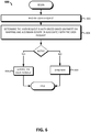
- FIG. 6 shows another example embodiment of a process 600 for servicing user requests by an NMS consistent with the present disclosure.
- a user request is received by the NMS, the user request may identify an operation to perform and include an equipment identifier for the operation.
- the user request may further include a domain identifier associated with the user, with the domain identifier corresponding to a domain identifier provisioned in the NMS.
- the NMS determines if the user request is authorized based at least in part on the partition mapping table 232 and the domain identifier associated with the user request.
- the NMS examines the partition mapping table 232 and the network element table 230 to determine what equipment a user can access based on their respective domain.
- domains may be associated with one or more cable landing stations, fiber cables, fiber optic pairs, and/or channel wavelengths.
- the NMS may allow or disallow access to equipment based on a user's domain and the associations defined for the same.
- the NMS generates a token to allow for repeated requests by the user to be validated without having to re-examine the partition mapping and network element tables. Therefore, subsequent user requests may be serviced based on the token file without performing database operations to determine if a user should have access to requested equipment, or not, as the case may be.
- the NMS may then service the request in act 606.
- Servicing of the user request may include, for instance, sending a message with topology information, log data for a target element, and/or adjusting an operational setting of a network element.
- the NMS may send a negative acknowledgement (NAK) in act 608 in the event the request is not authorized.
- NAK message may include an error code or other data, e.g., a character string, to indicate why the user request failed.
- a system for managing an optical communication system having an optical transmission path disposed between at least two cable landing stations and a plurality of network elements disposed along the optical transmission path, the system comprising a network element table, the network element table defining a plurality of network element definitions that each represent a different network element of the optical communication system, a partition mapping table to associate each of the plurality of network element definitions with at least one domain identifier based at least in part on a fiber pair and/or channel wavelength assigned to each network element, a network management system (NMS) controller to receive a user request to access a network element from a user, the user request being associated with a first domain identifier and including an identifier of an operation to perform, determine the user request is authorized to access the network element based on the partition mapping table indicating that the first domain identifier is associated with the network element of the user request, and in response to determining the user request is authorized, performing the operation.
- NMS network management system
- a computer-implemented method for managing an optical communication system having an optical transmission path disposed between at least two cable landing stations and a plurality of network elements disposed along the optical transmission path comprising receiving, by a controller, a user request to access a network element of the plurality of network elements from a user, the user request being associated with a first domain identifier and including an identifier of an operation to perform, and determine, by the controller, the user request is authorized to access the network element based on a partition mapping table indicating that the first domain identifier is associated with the network element of the user request, and in response to determining the user request is authorized, performing the operation.
- an optical system comprising an optical transmission path disposed between at least a first and second cable landing stations, a plurality of undersea optical components coupled to the optical transmission path, a network management system (NMS) controller to receive a user request to access an undersea optical component, the user request being associated with a first domain identifier and including an identifier of an operation to perform, determine the user request is authorized to access the undersea optical component based on a partition mapping table indicating that the first domain identifier is associated with the undersea optical component of the user request, and in response to determining the user request is authorized, performing the operation.
- NMS network management system
- Embodiments of the methods described herein may be implemented using a controller, processor and/or other programmable device. To that end, the methods described herein may be implemented on a tangible, non-transitory computer readable medium having instructions stored thereon that when executed by one or more processors perform the methods.
- the NMS 204 may include a storage medium to store instructions (in, for example, firmware or software) to perform the operations described herein.
- the storage medium may include any type of tangible medium, for example, any type of disk including floppy disks, optical disks, compact disk read-only memories (CD-ROMs), compact disk rewritables (CD-RWs), and magneto-optical disks, semiconductor devices such as read-only memories (ROMs), random access memories (RAMs) such as dynamic and static RAMs, erasable programmable read-only memories (EPROMs), electrically erasable programmable read-only memories (EEPROMs), flash memories, magnetic or optical cards, or any type of media suitable for storing electronic instructions.
- ROMs read-only memories
- RAMs random access memories
- EPROMs erasable programmable read-only memories
- EEPROMs electrically erasable programmable read-only memories
- flash memories magnetic or optical cards, or any type of media suitable for storing electronic instructions.
- any block diagrams herein represent conceptual views of illustrative circuitry embodying the principles of the disclosure.
- any block diagrams, flow charts, flow diagrams, state transition diagrams, pseudocode, and the like represent various processes which may be substantially represented in computer readable medium and so executed by a computer or processor, whether or not such computer or processor is explicitly shown.
- Software modules, or simply modules which are implied to be software may be represented herein as any combination of flowchart elements or other elements indicating performance of process steps and/or textual description. Such modules may be executed by hardware that is expressly or implicitly shown.
- processor may be provided through the use of dedicated hardware as well as hardware capable of executing software in association with appropriate software.
- the functions may be provided by a single dedicated processor, by a single shared processor, or by a plurality of individual processors, some of which may be shared.
- explicit use of the term "processor” should not be construed to refer exclusively to hardware capable of executing software, and may implicitly include, without limitation, digital signal processor (DSP) hardware, network processor, application specific integrated circuit (ASIC), field programmable gate array (FPGA), read-only memory (ROM) for storing software, random access memory (RAM), and non-volatile storage.
- DSP digital signal processor
- ASIC application specific integrated circuit
- FPGA field programmable gate array
- ROM read-only memory
- RAM random access memory
- non-volatile storage Other hardware, conventional and/or custom, may also be included.
Landscapes
- Engineering & Computer Science (AREA)
- Computer Networks & Wireless Communication (AREA)
- Signal Processing (AREA)
- Computer Security & Cryptography (AREA)
- Computing Systems (AREA)
- Computer Hardware Design (AREA)
- General Engineering & Computer Science (AREA)
- Power Engineering (AREA)
- Physics & Mathematics (AREA)
- Electromagnetism (AREA)
- Business, Economics & Management (AREA)
- Accounting & Taxation (AREA)
- Data Exchanges In Wide-Area Networks (AREA)
- Optical Communication System (AREA)
Description
- The present application generally relates to communication systems and, more particularly, to techniques for logically partitioning an optical transmission system to provide a single point of access for multiple client/customers which enables a per-client "view" of the optical transmission system that reflects a given client's authorized equipment and privileges based on the user's corresponding domain.
- Network management may be conducted at different levels in various types of optical networks to avoid network failures and to assure network performance. In a communication network, an element management system (EMS) may be used to supervise and manage network elements within a network. A communication network may also include a network management system (NMS) to manage the overall network by communicating with several EMSs.
- In an optical communication system such as a wavelength division multiplexed (WDM) system, for example, terminal or cable stations may be interconnected by cable segments to form a network. The network elements in an optical communication system may include equipment located at a cable station (e.g., terminal equipment and power feed equipment, computers, phones, printers and so on) as well as equipment associated with the cable station (e.g., adjacent repeaters, branching units and equalizers). In such a system, an EMS may be located at a cable station (or at a separate location) and used to manage the network elements associated with this cable station. The EMS may include one or more servers for performing the element management functions and one or more workstations for providing a user interface (e.g., to display the information associated with the network elements managed by the EMS). An NMS may be located at one of the cable stations or at a separate location for managing the overall optical communication system or network.
- Optical communication systems in the subsea context are often owned and operated by consortiums of multiple parties, some or all of which desire complete data and operational independence for managing their part of the overall communication system. Previous approaches for supporting this access includes providing dedicated Element Management Systems (EMSs) and Network Management System (NMSs) hardware and software for each party, possibly in addition to separate server equipment for the common part of the system that all parties could access such as power feed equipment (PFEs). The dedicated EMS and NMS hardware and software ensures that each party can manage only their specific portions of an optical communication system as well as commonly owned equipment, as well as the ability to manage user logins and privilege levels for the equipment at a fine-grain level. However, providing dedicated EMS and NMS systems raise numerous technical challenges and can significantly increase costs related to hardware, software licensing, and technicians to maintain duplicate systems.
- 1 Document
US103149B1 discloses a system and method that facilitates audits of for instance optical network concentrators and presents results in a user friendly format. An automated network communication device audit tool gathers device information, parses the gathered information automatically, determines if additional information is required, analyzes the characteristic and operations of said network communications device and reports network communication device information including identification of problems and potential problems. - Document
WO 00/62575A1 - Document
US 2017/331791 A1 discloses a system that provides cloud-based identity and access management. The system receives a request for an identity management service for accessing an application and determines a user from a header value of the request. The system looks up a policy configured to be applied for the user, and applies the policy to the request. The system then sends the request to a microservice based on a result of the applying of the policy to the request, where the microservice performs the identity management service for accessing the application. - Reference should be made to the following detailed description which should be read in conjunction with the following figures, wherein like numerals represent like parts:
-
FIG. 1 is a simplified block diagram of one exemplary embodiment of an optical system consistent with the present disclosure. -
FIG. 2 simplified block diagram of an exemplary embodiment a network management system (NMS) suitable for use in the optical communication system ofFIG. 1 . -
FIG. 3 is an example of a system partitioning configuration file consistent with an embodiment of the present disclosure. -
FIG. 4 is a simplified block diagram of an example NMS architecture consistent with the present disclosure. -
FIG. 5 shows an example method for provisioning an optical communication system to provide secured partitioning in accordance with an embodiment of the present disclosure. -
FIG. 6 shows an example method for servicing user requests within an optical communication system implementing secured partitioning in accordance with an embodiment of the present disclosure. - As discussed above, providing dedicated NMS server systems to permit multi-party NMS data access and control is a relatively inefficient use of hardware as each customer is given, essentially, duplicate hardware to manage login credentials, equipment privileges, and to handle requests to perform system operations and collect diagnostic data from network elements. While a single set of network management hardware and software remedies these inefficiencies in theory, the implementation of such as system raises technical complications due to the nature of optical communication systems whereby some equipment may be specific to a particular customer, while other equipment may be commonly owned.
- These multi-party challenges may be better understood by way of a simplified example. Consider a four fiber pair cable system that may be owned by a consortium of four different parties each owning a different fiber pair of the four fiber pairs and associated Line Terminating Equipment (LTE). Some LTE may be common equipment owned by all parties such as Power Feed Equipment (PFE) that provides power along the fiber optic cable. Further, some common equipment such as Line Monitoring Equipment (LME) may be commonly owned, but may store data on a per-fiber pair basis. In this example, each party may desire access to the LME equipment for operational purposes, but may also desire that data specific to their fiber pairs be private and inaccessible to other parties in the system. Moreover, each party may desire to have fine-grain control over their specific user logins without other parties having the ability to "see" the user login data tables and security privileges.
- Thus, the present disclosure is generally directed an approach that allows for a single NMS system to manage data access and control for N number of customer domains (or simply domains) and associated users. In particular, an NMS consistent with the present disclosure may include a scheme/configuration that logically partitions the optical communication system by domain. For each domain, partitioning can further define per-user access constraints and privileges including access to specific equipment by, for instance, fiber pair designation, wavelength designation, specifically identified hardware elements, component categories (e.g., repeaters, OADMS, PFEs, etc.,) or any combination thereof. The NMS system may utilize a proxy server approach to authentication, e.g., using Remote Authentication Dial In User Service (RADIUS) or other suitable approach, that allows for each party/customer to maintain separate authentication databases that can establish user logins, access privileges, and equipment-specific constraints. The NMS may therefore validate users via the proxy server, and enforce domain restrictions via the partitioning information such that each user has a secure 'view' of the optical communication system that includes only those portions of the system associated with their particular domain. Users may access the NMS directly via a graphical user interface (GUI) or indirectly via, for instance, a Representational State Transfer (ReST) based Application Programming Interface (API) for remote Operations System Support (OSS) programmed management.
- Therefore, users can have access to their respective portions of the system, including commonly owned elements, based on a secure, transparent partitioning scheme provided by the NMS that can provide fine-grain access to equipment based on a particular fiber cable, fiber pair(s), and/or channel wavelengths associated with a given domain. Moreover, an NMS consistent with the present disclosure allows for each domain to remotely host their own user credentials database in separate third-party server, which can increase isolation between system elements and the remote third-party servers for the purposes of data security and ease of management. Thus, the overall number of server components may be reduced relative to approaches that provide a dedicated NMS and/or EMS server system for each party desiring to access the system, and in some cases server processes consistent with the present disclosure can be hosted via public or private Cloud services. Numerous benefits of this reduction of hardware and server components/functions will be apparent in view of this disclosure and include, for instance, decreased complexity for installs and maintenance, increased rack/server room space for other equipment, fewer technicians to train, and greater flexibility in providing and administering API and GUI access to NMS server functionality.
- Turning to the Figures,
FIG. 1 shows anoptical communication system 100 consistent with the present disclosure. Theoptical communication system 100 is shown in a highly simplified form for ease of description and not by limitation. Theoptical communication system 100 may be implemented as a subsea optical communication system wherein at least a portion of the elements are located below sea level. Further, theoptical communication system 100 may be implemented as a wavelength division multiplexing (WDM) system capable of transmitting via a plurality of channel wavelengths. As shown, theoptical communication system 100 includes anoptical transmission path 103 that extends between a plurality of cable landing stations, namely cable landing stations 102-1, 102-2 and 102-3. - As shown, the
optical communication 100 includes an optical fiber cable collectively shown as 110 that spans a relatively large geographic distance (e.g., tens, hundreds, or thousands of kilometers). The undersea optical network may thus comprise a plurality of "wet" optical components that are disposed along the sea floor or disposed on a sea-based platform, for example. However, cable segments are not necessarily limited in this regard and theoptical communication system 100 may include, at least in part, some lengths of land-based optical fiber segments. Although examples and scenarios disclosed herein refer to cable landing stations or CLSs, the disclosure is not necessarily limited in this regard. For example, the techniques disclosed herein are equally applicable to any station located within the optical communication system including, for example, Network Operation Centers (NOCs) and Remote Operation Positions (ROPs), just to name a few. - Continuing on, the
optical transmission path 103 includes at least oneoptical cable 110 comprising one or more optical fiber pairs. Theoptical transmission path 103 includes a plurality of optical components including repeaters 118-1, 118-2, and one or more branching units, e.g.,BU 125. The BUs can include reprogrammable optical add/drop multiplexers (ROADMs) or other suitable optical filters/components (e.g., that can include circuitry for remote monitoring and control) for sending and receiving channel wavelengths from a branch path, e.g.,branch path 114. Each cable landing station may include an Element Management System (EMS) for providing access to various optical components and for providing an interface to Command/Response Elements (CREs) within the system. - Each of the cable landing stations 102-1 to 102-3 may be disposed along a shore or on a platform. Each of the cable landing stations 102-1 to 102-3 may include line terminating equipment (LTE) such as channel line cards (not shown), power feed equipment (PFE) 112-1, and so on. The PFE 112-1 may be configured to provide a constant voltage or constant current along the
optical transmission path 103. - As further shown, the first cable landing stations 102-1 includes an NMS 104-1, EMS 106-1 and LME 108-1. The NMS 104-1 may be implemented as the
NMS 204 discussed in further detail with reference toFIG. 2 . Each NMS may be configured to communicate with N number of EMS systems. Each of the EMS systems may be configured to communicate with optical components such as repeaters and other elements local or otherwise adjacent to a given cable landing station. LME equipment may be utilized to perform high loss loopback (HLLB) or other measurements to ensure nominal performance and to detect faults, e.g., cable breaks, along theoptical transmission path 103. - Optionally, more than one cable landing station may include similar components for redundancy and fault tolerance, and for local administration of network elements. For example, the second cable landing station 102-2 can include NMS 104-2, EMS 106-2 and LME 108-2. As discussed further below, each of the NMS components 104-1, 104-2, may collectively form a
single NMS system 204 whereby users can log into any NMS component, e.g., directly via a graphical user interface (GUI), or via an API, and have requests serviced. In this example, one of the NMS components may operate as a master whereby the slave NMS systems proxy or otherwise forward requests to the master for handling. In the event the master NMS goes offline, theoptical communication system 100 may be configured to automatically switch a slave NMS into the master role. -
FIG. 2 shows an example network management system (NMS)architecture 200 consistent with the present disclosure. TheNMS architecture 200 is depicted in a highly simplified form for clarity and not limitation. TheNMS architecture 200 may be implemented in different configurations including, for instance, a plurality of NMS servers, EMS servers, LME, and so on, to collectively provide theNMS architecture 200. In this way, components may be distributed among multiple cable landing stations, e.g., CLS 102-1 .. CLS 102-3 ofFIG. 1 , to provide redundancy, fault tolerance and to provide multiple points of access for users of theNMS architecture 200. TheNMS 204 may be therefore collectively be implemented as a single NMS server, e.g., NMS 104-1, or may comprise a plurality of NMS systems as shown inFIG. 1 , e.g., NMS 104-1, 104-2. - As further shown, the
NMS 204 includes a plurality of associated components including a anauthentication interface 206, asystem resources database 212, asecurity manager 220, and auser interface 224. TheNMS 204 may be implemented in hardware (e.g., circuitry), software, public/private cloud, or a combination thereof. In an embodiment, theNMS 204 may be implemented at least in part as a plurality of non-transitory instructions stored inmemory 207 that may be executed by a controller 205 (which may also be referred to as an NMS controller) to carry out the NMS processes, e.g., processes 500 and 600 ofFIG. 5 and6 , respectively. A controller, as generally referred to herein, may be implemented as a processor (e.g., x86 process or a virtual computer), field programmable gate array (FPGA), an application-specific integrated circuit (ASIC), or any other suitable processing device/circuitry. - The
user interface 224 may comprise graphical user interface (GUI) components and/or API components to receive and process requests from a user, e.g., user 229. In an embodiment, the API of the user interface may implement a ReST architecture. Thesecurity manager 220 may be configured to ensure that requests received from a user are permissible based on the user's associated privileges and access rights. To perform authentication and validation of user rights when servicing requests from a user, thesecurity manager 220 may utilize theauthentication interface 206. Theauthentication interface 206, which may also be referred to as a proxy authentication interface, can communicate with a remote authenticator(s) 214 by way of awide area network 208, e.g., the Internet. - Each the
remote authenticator 214 may correspond with a different customer domain and be configured to service authentication requests from theauthentication interface 206. As discussed in further detail below, the authentication data in each remote authenticator may be stored in a standardized way, e.g., using a predefined schema, to allow each entity to provision their respective databases in a manner that comports with requirements of theNMS 204. Thus, thesecurity manager 220 may transparently select a particularremote authenticator 214 based on a known association (e.g., stored in the memory 207) between the user 229 and their respective entity/domain. Alternatively, the user 229 may include an entity/customer identifier when communicating with theNMS 204 that allows the same to select an appropriate remote authenticator. In this case, thesecurity manager 220 may then select aremote authenticator 214 based on the identified entity and communicate with the identified entities' remote authenticator for validation and authentication purposes. Note while the embodiment ofFIG. 2 includes communication with a remote authenticator, this disclosure is not limited in this regard. For instance, theNMS 204 may utilize a local database for authentication purposes and may use the local database to authenticate users, or may both locally authenticate some users while using remote authenticators to authorize others depending on a desired configuration. - In addition to providing authentication data, each remote authenticator may further define access attributes for each user. As discussed in greater detail below with reference to Table 1, access attributes may define what equipment within the optical communication system 1 a user has access to by, for instance, defining a particular category/type of equipment a user may access and their rights and access privileges for that equipment type. The
security manager 220 then allows or disallows requests to equipment from the user 229 based on their access attributes and the partition mapping table, which is discussed in further detail below. - The
NMS 204 can include asystem resources database 212 stored in thememory 207. Thesystem resource database 212 may be distributed among a plurality of components including multiple NMSs and EMSs, for instance, and the embodiment shown inFIG. 2 is not intended to be limiting. For example, each cable landing station may include an EMS that stores data representative of each associated optical component including, for instance, line cards, PFEs, repeaters, LMEs, equalizers, computer servers, and branching units. TheNMS 204 may then utilize the EMS data from each of the cable landing stations to collectively and logically form the network elements table 230, although the data may be physically distributed among different cable landing stations. Thesystem resources database 212 can include structured query language (SQL) databases, flat files (e.g., unique universal markup language (XML)), in-memory data structures, or any combination thereof. - Continuing on, the partition mapping table 232 may be utilized to associate network elements from the network elements table 230 with customer domains/entities. For instance, the partition mapping table 232 may include a hierarchal structure that associates domains (which may be referred to as a customer ID), with cable landing stations. The partition mapping may then further define associations down to the equipment level, fiber optical cable, fiber pair(s), and/or one or more target wavelengths. As described further below with reference to
FIG. 3 , the partition mapping table 232 may include one or more definitions that manifest as an XML document, although other types of file formats are within the scope of this disclosure. TheNMS 204 may then utilize entries to allow user access to equipment/elements within thesystem 100 based on, for instance, a corresponding entry in the network elements table that associates equipment with its respective cable station, fiber optic cable(s), fiber pair(s), and/or channel wavelength(s). - Note that each customer domain may be associated with different cable landing stations, or two or more customer domains may be associated with one or more common cable landing stations. The secured partitioning scheme disclosed herein advantageously allows for such mixed domains by enabling fine-grain control over what specific elements a domain has access to down to the channel wavelength-level, depending on a desired configuration.
- Thus, in operation, the
NMS 204 can receive requests from the user 229 and authenticate the user 229 via a remote authenticator and to receive access attributes associated with the user. TheNMS 204 may then service requests from the user 229 and validate the requests based on the access attributes and thesystem resources database 212. In particular, the customer ID (or domain ID) associated with the user 229 may be used to determine what equipment is authorized based on one or more entries in the partition mapping table 232 as discussed above. - By way of example, consider a scenario where the user 229 requests log data for a first repeater R1 on a first fiber pair (PI) via the
user interface 224. In this example, theNMS 204, by way of thesecurity manager 220, may determine if the request should be serviced by examining the access attributes for the user 229, the network elements table 230, and the partition mapping table 232. If the first repeater R1 is associated with the user's customer domain, e.g., based on an entry in the partition mapping table 232 that associates the user's customer domain with the first fiber pair PI and a corresponding entry in the network elements table 230 that associates the first repeater (R1) with the first fiber pair PI, the request may then be serviced by theNMS 204 by communicating with the repeater R1 or the EMS responsible for the repeater R1. Note, the data retrieved from the repeater R1 by theNMS 204 may be limited to only that data corresponding to the first fiber pair although repeater R1 may be associated with multiple fiber pairs. - In an embodiment, the
NMS 204 may be configured to provide topology information to the user 229 based on a request from the same. The topology information may include data that represents the network elements the user 229 has access to. In an embodiment, the topology information is derived from the network element table 230 and the partition mapping table 232. - The topology information may than be utilized by a GUI of a computing device, e.g., smart phone, laptop, tablet, of the user 229 to visually present what particular elements the user 229 has access to. In some cases, the topology information may be implemented as a Common Object Request Broker Architecture (CORBA) message that can be utilized by a user device to generate a dynamic user interface (See
FIGs. 5 and6 ). In turn, the user 229 may make requests to specific equipment via the NMS based on the visualized topology information. For instance, a map may be presented via a GUI of the computing device that allows a user to select an icon or other visual indicator that represents equipment disposed along theoptical transmission path 103. The user 229 may then request diagnostic data, adjust settings, or otherwise post requests to their assigned network elements/equipment. - Initial provisioning for the
NMS 204 includes generating an authentication server configuration for each authenticator, e.g.,remote authenticators 214. The authentication server configuration allows for an arbitrary number of independent entities per optical communication system in a manner that allows each user to authenticate against data stored on within their respective entity's authentication database. For instance, requests to access theNMS 204 may be handled transparently via theauthentication interface 206 that communicates with a remote aremote authenticator 214 via a wide area network (WAN) 208, e.g., via the Internet. Thecommunication 210 between theauthentication interface 206 and theremote authenticator 214 may utilize a RADIUS authentication approach which can utilize an Authentication, Authorization, and Accounting (AAA) protocol. Note, other authentication systems may be utilized such as TACACS+ or Red Hat Identity Manager (IdM), just to name a few. - In any event, any number of remote authenticators may be utilized to allow for N different entities to utilize the
NMS 204 and authenticate using their own server. The authentication proxy server 218 can determine which physical server or virtual instance to address (e.g., by domain) to retrieve authentication (e.g., login access) and authorization (e.g., access attribute) information. - In an embodiment, each authentication server of the
remote authenticators 214 can be configured with a configuration that enables users to authenticate with theNMS 204 and obtain appropriate equipment access credentials. For each user, equipment access attributes, or simply access attributes, may be stored in a table, flat file, or other data store by an authentication server. In some cases, access attributes manifest as predefined definitions, and the predefined definitions being uniform across all authentication servers based on a common definition/specification. The access attributes may establish the category of equipment a given user is able to access. One example specification for access attribute definitions is shown in Table 1.Table 1. ATTRIBUTE Code Type TEMSUser 0x1 [Global Access] WetPlantUser 0x2 [Global Access] PFEUser 0x3 Limited Access LMSUser 0x4 Limited Access TLAUser 0x5 Limited Access CREUser 0x6 Limited Access sWMUUser 0x7 Limited Access WSSROADMUser 0x8 Limited Access #Special Restricted Attribute RestrictedUser 0x9 Restricted - As shown above, basic access attributes include three types of user access attributes. The first type includes Global Access Attributes such as: TEMSUser, WetPlantUser. A user assigned with the attribute TEMSUser can access any resource available to the
NMS system 204. Likewise, a user assigned with the attribute WetPlantUser can access any wet plant network element available via theNMS system 204, e.g., repeaters, equalizers, undersea power conversion units, predetermined wavelength filtering units, and so on. - A second type includes limited access to a specific network element. In some cases, a user assigned to specific network element or group of elements. In the example definitions provided above, users assigned the PFEUser attribute has access to Power Feed Equipment (PFE); users assigned the LMSUser attribute has access to Line Monitoring System (LMS) devices; users assigned the Terminal Line Amplifier (TLA) attribute has access to TLA devices; users assigned the CREUser attribute have access to Command Response Equipment (CRE), users assigned the sWMUUser have access to Switched Wavelength Multiplexing Units (sWMUs), and users assigned the WSSROADMUser attribute have access to Wavelength Selectable Switched Reconfigurable Optical Add Drop Multiplexers (WSSROAMs). The code and type definitions define the unique ID for the attribute and the type represents the type of access the attribute grants as enumerated and discussed above.
- A third type includes restricted access. Users assigned with the RestrictedUser attribute can be blocked from access equipment in a particular cable station but allow access potentially at another. Note the provided example attributes are not intended to be limiting, and moreover, do not represent an exhaustive list of equipment type and access control categories. Numerous other types of equipment and access categories/behaviors are within the scope of this disclosure.
- Continuing on, additional attribute definitions may define the access rights for each of the access attributes discussed above with regard to table 1. One such example is provided in Table 2.
Table 2. Attribute Value Access Value Code TEMSUser View 0x1 TEMSUser Control 0x2 TEMSUser Admin 0x3 - Each user access attribute value can be assigned one of three access right possibilities, namely, view, control and admin. As shown above in Table 2, a user assigned the TEMSUser attribute may then further be assigned one of three access types: read-only via a View attribute, read-write via a Control attribute, and an admin-level for administration tasks beyond read-write such as firmware upgrades via the Admin attribute.
- User entries may then be generated and assigned with attributes including a customer domain, a username, a password, global or specific system resource access (e.g., as discussed above with regard to Table 1), and access rights to the assigned resources (e.g., as discussed above with regard to Table 2). Therefore, users may be generated and the system may be partitioned by domain (customer) with specific access to types of system resources with specific access rights. A user is thus partitioned by domain but not partitioned for specific access by customer and by cable station.
- A system partition configuration file may be generated for the
NMS 204 and stored as the partition mapping table 232. Generation of the system partition configuration file can include defining one or more rules that establish the specific equipment each customer can access, and the access rights for that equipment. Rule generation can further include defining what equipment a domain is allowed to access based on identifying one or more cable landing stations, fiber optic cables, fiber pairs, channel wavelengths, and/or specific equipment. The system partition configuration file may manifest as a XML description that allows for robust and full partitioning by domain and by resource. The partition configuration file may be system-specific and replicated such that theuser interface 224 can access the same regardless of where the partitioning server function is instantiated/executed in the system. - One such example
XML configuration file 300 suitable for use within the partition mapping table 232 is shown inFIG. 3 . As shown, thepartitioning definition file 300 is hierarchical and broken up into sections. Each shown section will be discussed in turn but is not intended to be limiting. System level information can include, for example, system name, number of cable stations, number of fiber pairs, and number of customers/domains. Customer centric information can include, for example, partitioning information that pertains to users logged in directly or indirectly (e.g., via an API) of that customer type. Such information can define Wet Plant access for that user entity by cable and fiber pair (e.g.,WSS ROADM # 3, oncable # 1, accessingADMs # 1 and #2 in the <Wet Plant> Section). Further, the information can define Station partitioning access for that user entity such as in the NYC cable station shown inFIG. 3 . The stationing partitioning access definition can further define what fiber pairs in the cable station the user entity can access, e.g.,fiber pair number 1 in the example below; define specific network element number (NE) access in that cable station for that user entity, e.g., NYC cable station,PFE # 1 oncable # 1 with unrestricted access (access may be determined by the user's normal access rights in this case); andLME # 1 with Restricted access (e.g., a user of restricted type cannot access the LMS in this case). In some cases, the definition file can go as fine-grain as the wavelength or band level in an undersea ROADM, for instance, if desired. - As discussed above, the
NMS 204 can include asecurity manager 220 that may be disposed between theuser interface 224 and theNMS 204. Theuser interface 224 may implement a ReST API or a user interface for direct access, although other architectures are within the scope of this disclosure. Thesecurity manager 220 may intercept requests made through theuser interface 224 and can validate the request. In the context of authentication, e.g., during login, thesecurity manager 220 may communicate with a remote authenticator, e.g.,remote authenticators 214, via the authentication interface. The response from a given authenticator may then be communicated back to a user 229, e.g., in the form of an acknowledgement (ACK) or negative acknowledgement (NAK). - The
security manager 220 may also cache in a memory the user access attributes received from an authenticator. Thesecurity manager 220 may also access the partitioning configuration file within the partition mapping table 232, as discussed above, and cache the same in thememory 207. Utilizing the user access attributes and the partitioning configuration file, thesecurity manager 220 can generate an access token 242 (which may be stored in the memory 207) that includes information that allows the user 229 to make subsequent requests in a secure partitioned manner. Theaccess token 242 may be implemented as, for instance, a ALG_HS512 encrypted JavaScript Object Notation (JSON) Web Token (JWT). Theaccess token 242 may include a value representing the user's domain, and the user 229 may provide the access token 242 (or a representation thereof) when sending requests via theuser interface 224. Theaccess token 242 may further include an expiration value that causes the security manager to invalidate the access token after a predetermined period of time, e.g., based on a timer. In the event an access token expires, the user 229 may re-establish the session through a re-authentication procedure, e.g., re-logging in. - Continuing on, the
security manager 220 can validate all requests to theNMS 204 for system resources, and management data such as alarms, performance data, control operations, and so on. To validate requests, thesecurity manager 220 may validate the access token against a currently cached data within thememory 207 that provides an authentication record and resource authorization information. For each request, thesecurity interface 220 may then examine the partitioning assigned to a given domain/user and will either validate (e.g., allow) access to the associated station and resource(s) being requested, or alternatively, disallow the request (e.g., based on user, domain, and/or associated partitioning attributes). In the event the request is validated, thesecurity manager 220 may then allow the request to be satisfied by, for instance, theNMS 204 sending back requested topology information and/or requested management data. - Requests may be handled via a user interface local to the
NMS 204 and/or an external API network management operation request to/from theNMS 204, that in turn validates all requests on a per-user or per-customer domain basis, as discussed above. In the case of the client GUI, theNMS 204 can display an un-partitioned system which can display all resources/equipment available in a system. From the perspective of the user 229, the partitioning scheme of theNMS 204 as controlled by thesecurity manager 220 appears to be transparent. Stated differently, the user sends requests via theuser interface 224, with those requests being validated by thesecurity manager 220 or not, as the case may be. The user 229 thus has access to equipment that is assigned to their particular customer domain. - In an embodiment, and in the context of a partitioned system, after successful login or API requests for user validation, the
NMS 204 can return the token 242, which the client or API can cache and supply with every network management request. On receiving a client request, for example for access system level information, theNMS 204 may return only information related to the cable and fiber pair (or channel wavelength) which the calling entity has access to. The GUI may then only display cable, fiber pair and related network element resources based on the partitioned information it gets from theNMS 204, i.e., the topology information. - For example, if the user/client 229 request is from a user that only has access to
fiber pair # 1, theNMS 204 may only return information related to that configuration in the CORBA message that uses an Interface Definition Language (IDL) data structure to define partitioning access. The client may then read this IDL definition and dynamically "learn" what features/entities of the system are available on the GUI. From that point, the user can initiate further system management operations based on their defined access rights to the available resources (View or Control). - The
NMS 204 may include a ReST API that can work in a similar fashion. After the API makes a call to validate a given user, the token, e.g., token 242, may be returned in the API call and that token can be passed with all future ReST calls otherwise the call may be rejected by theNMS 204. Partitioned information in the JavaScript Object Notation (JSON) format can be passed back to the user for only those resources that calling entity can access for GET operations. ReST Control operations (PUT, POST and DELETE) may be only allowed if the calling entity has control access to the requested resources. - Continuing on, in an embodiment, the
NMS 204 can include a plurality of server components for servicing of requests for different aspects of the optical communication system.FIG. 4 shows a plurality of example server components for servicing user requests. As shown inFIG. 4 , the server modules include awet plant manager 404, acommon shelf manager 406, a linemonitoring system manager 408, a linemonitoring equipment manager 410, a powerfeed equipment manager 412, a commandresponse equipment manager 414, and a line terminatingequipment manager 416. Each will now be discussed in turn, but the particular server component examples discussed below are not exhaustive and other embodiments are within the scope of this disclosure. - The
wet plant manager 404 can manage requests for resources and configuration related to wet Plant equipment such as Power Switched Branching Units (PSBUs), Dispersion Compensation Units (DCUs), Switched Wavelength Multiplexing Units (sWMUs) and WSS ROADMS. Thecommon shelf manager 406 can manage requests for resources related to the Line Terminating Equipment Shelf. TheLMS manager 408 can handle resources related to the Line Management System and related data interfaces such as High Loss Loopback (HLLB) data, Optical Spectrum Monitoring (OSM) data, and Optical Time Domain Reflectometer (OTDR) data. LineMonitoring Equipment manager 410 can manage requests for Line Monitoring Hardware specific resources such as port configuration, board temperature and operational status. ThePFE manager 412 can manage requests for Power Feed Equipment data such as hardware configuration and voltage and current data for the system. TheLTE manager 416 can manage requests for configuration and resources related to all other Line Terminating equipment such as Dry ROADMs, Internal Loading Equipment (ILE), and Terminal Line Amplifiers (TLAs). The CommandResponse Equipment manager 414 can manage requests for configuration and operation of the Command Response Equipment (CRE) used to communicate with the Wet Plant devices. - Aspects and embodiments of the foregoing may be implemented in one or more processes executable by a controller of an NMS system consistent with the present disclosure, e.g., the
controller 205 ofFIG. 2 .FIG. 5 shows onesuch process 500 for configuration of an NMS system consistent with the present disclosure. - The
process 500 includes acts of configuring authenticators, a partitioning configuration file, and provisioning the NMS system. Inact 504, theprocess 500 includes configuring authenticator(s). Configuration of authenticators, e.g.,remote authenticators 214, may include configuring one or more remote computer systems to handle remote authorization requests using, for instance, a AAA protocol. Configuration of the authenticators may further include deploying a common database schema that allows for users and associated access attributes to be stored, e.g., as discussed above with regard to Table 1, and retrieved in a common format. - In
act 506, theprocess 500 further includes generating a partition configuration file such as the partition configuration XML file shown and discussed above with reference toFIG. 3 . The partition configuration may establish a plurality of domains, associated equipment, and access rules/properties. Access for each customer domain may be relatively fine-grain and may include definitions to limit access to equipment associated with one or more cable landing stations, optical cables, optical fiber pairs, channel wavelengths, or any combination thereof. - In
act 506, theprocess 500 further includes provisioning an NMS system, e.g., theNMS 204. Provisioning the NMS system can include adding entries in the network elements table 230, with each entry defining equipment-centric details such as the type of equipment, IP address, cable landing station, optical fiber identifier, fiber pair(s), and/or associated channel wavelength(s). Act 506 may further include adding entries in the partition mapping table 232 to establish associations between domains and equipment within the network elements table. -
FIG. 6 shows another example embodiment of aprocess 600 for servicing user requests by an NMS consistent with the present disclosure. Inact 602, a user request is received by the NMS, the user request may identify an operation to perform and include an equipment identifier for the operation. The user request may further include a domain identifier associated with the user, with the domain identifier corresponding to a domain identifier provisioned in the NMS. - In
act 604, the NMS determines if the user request is authorized based at least in part on the partition mapping table 232 and the domain identifier associated with the user request. In an embodiment, the NMS examines the partition mapping table 232 and the network element table 230 to determine what equipment a user can access based on their respective domain. As discussed above, domains may be associated with one or more cable landing stations, fiber cables, fiber optic pairs, and/or channel wavelengths. Thus, the NMS may allow or disallow access to equipment based on a user's domain and the associations defined for the same. In some cases, the NMS generates a token to allow for repeated requests by the user to be validated without having to re-examine the partition mapping and network element tables. Therefore, subsequent user requests may be serviced based on the token file without performing database operations to determine if a user should have access to requested equipment, or not, as the case may be. - In response to user request being authenticated, the NMS may then service the request in
act 606. Servicing of the user request may include, for instance, sending a message with topology information, log data for a target element, and/or adjusting an operational setting of a network element. On the other hand, the NMS may send a negative acknowledgement (NAK) inact 608 in the event the request is not authorized. The NAK message may include an error code or other data, e.g., a character string, to indicate why the user request failed. - In accordance with an aspect of the present disclosure a system for managing an optical communication system is disclosed. The optical communication system having an optical transmission path disposed between at least two cable landing stations and a plurality of network elements disposed along the optical transmission path, the system comprising a network element table, the network element table defining a plurality of network element definitions that each represent a different network element of the optical communication system, a partition mapping table to associate each of the plurality of network element definitions with at least one domain identifier based at least in part on a fiber pair and/or channel wavelength assigned to each network element, a network management system (NMS) controller to receive a user request to access a network element from a user, the user request being associated with a first domain identifier and including an identifier of an operation to perform, determine the user request is authorized to access the network element based on the partition mapping table indicating that the first domain identifier is associated with the network element of the user request, and in response to determining the user request is authorized, performing the operation.
- In accordance with another aspect of the present disclosure a computer-implemented method for managing an optical communication system having an optical transmission path disposed between at least two cable landing stations and a plurality of network elements disposed along the optical transmission path is disclosed. The method comprising receiving, by a controller, a user request to access a network element of the plurality of network elements from a user, the user request being associated with a first domain identifier and including an identifier of an operation to perform, and determine, by the controller, the user request is authorized to access the network element based on a partition mapping table indicating that the first domain identifier is associated with the network element of the user request, and in response to determining the user request is authorized, performing the operation.
- In accordance with another aspect of the present disclosure an optical system is disclosed. The optical system comprising an optical transmission path disposed between at least a first and second cable landing stations, a plurality of undersea optical components coupled to the optical transmission path, a network management system (NMS) controller to receive a user request to access an undersea optical component, the user request being associated with a first domain identifier and including an identifier of an operation to perform, determine the user request is authorized to access the undersea optical component based on a partition mapping table indicating that the first domain identifier is associated with the undersea optical component of the user request, and in response to determining the user request is authorized, performing the operation.
- The foregoing description of example embodiments has been presented for the purposes of illustration and description. It is not intended to be exhaustive or to limit the present disclosure to the precise forms disclosed. Many modifications and variations are possible in light of this disclosure. It is intended that the scope of the present disclosure be limited not by this detailed description, but rather by the claims appended hereto.
- Embodiments of the methods described herein may be implemented using a controller, processor and/or other programmable device. To that end, the methods described herein may be implemented on a tangible, non-transitory computer readable medium having instructions stored thereon that when executed by one or more processors perform the methods.
- Thus, for example, the
NMS 204 may include a storage medium to store instructions (in, for example, firmware or software) to perform the operations described herein. The storage medium may include any type of tangible medium, for example, any type of disk including floppy disks, optical disks, compact disk read-only memories (CD-ROMs), compact disk rewritables (CD-RWs), and magneto-optical disks, semiconductor devices such as read-only memories (ROMs), random access memories (RAMs) such as dynamic and static RAMs, erasable programmable read-only memories (EPROMs), electrically erasable programmable read-only memories (EEPROMs), flash memories, magnetic or optical cards, or any type of media suitable for storing electronic instructions. - It will be appreciated by those skilled in the art that any block diagrams herein represent conceptual views of illustrative circuitry embodying the principles of the disclosure. Similarly, it will be appreciated that any block diagrams, flow charts, flow diagrams, state transition diagrams, pseudocode, and the like represent various processes which may be substantially represented in computer readable medium and so executed by a computer or processor, whether or not such computer or processor is explicitly shown. Software modules, or simply modules which are implied to be software, may be represented herein as any combination of flowchart elements or other elements indicating performance of process steps and/or textual description. Such modules may be executed by hardware that is expressly or implicitly shown.
- The functions of the various elements shown in the figures, including any functional blocks labeled as "processor", may be provided through the use of dedicated hardware as well as hardware capable of executing software in association with appropriate software. The functions may be provided by a single dedicated processor, by a single shared processor, or by a plurality of individual processors, some of which may be shared. Moreover, explicit use of the term "processor" should not be construed to refer exclusively to hardware capable of executing software, and may implicitly include, without limitation, digital signal processor (DSP) hardware, network processor, application specific integrated circuit (ASIC), field programmable gate array (FPGA), read-only memory (ROM) for storing software, random access memory (RAM), and non-volatile storage. Other hardware, conventional and/or custom, may also be included.
- Unless otherwise stated, use of the word "substantially" may be construed to include a precise relationship, condition, arrangement, orientation, and/or other characteristic, and deviations thereof as understood by one of ordinary skill in the art, to the extent that such deviations do not materially affect the disclosed methods and systems. Throughout the entirety of the present disclosure, use of the articles "a" and/or "an" and/or "the" to modify a noun may be understood to be used for convenience and to include one, or more than one, of the modified noun, unless otherwise specifically stated. The terms "comprising", "including" and "having" are intended to be inclusive and mean that there may be additional elements other than the listed elements.
- Although the methods and systems have been described relative to a specific embodiment thereof, they are not so limited. Obviously, many modifications and variations may become apparent in light of the above teachings. Many additional changes in the details, materials, and arrangement of parts, herein described and illustrated, may be made by those skilled in the art.
Claims (14)
- A system for managing an optical communication system (100) having an optical transmission path (103) disposed between at least two cable landing stations (102-1, 102-2, 102-3) and a plurality of network elements disposed along the optical transmission path, the system comprising:a network element table (230), the network element table (230) defining a plurality of network element definitions that each represent a different network element of the optical communication system (100);a partition mapping table (232) to associate each of the plurality of network element definitions with at least one domain identifier based at least in part on a fiber pair and/or channel wavelength assigned to each network element,a network management system (NMS) controller (205) associated with a network management system (NMS) (104-1, 204) to:receive a user request to access a network element from a user, the user request being associated with a first domain identifier and including an identifier of an operation to perform;determine the user request is authorized to access the network element based on the partition mapping table indicating that the first domain identifier is associated with the network element of the user request; and in response to determining the user request is authorized, performing the operation,the system being characterized by a plurality of authenticator servers for storing a plurality of user access credentials and associated user access attributes, wherein the NMS includes an authentication interface to communicate with the plurality of authenticator servers to validate user credentials received within a user request, and wherein each of the plurality of authenticator servers is associated with a different domain identifier.
- The system (100) of claim 1, with one or more of the following:wherein each of the plurality of the authenticator servers implement an Authentication, Authorization, and Accounting (AAA) protocol to receive authentication requests from the NMS controller (205),wherein the user access attributes define a first type of equipment a user has access to and one or more privileges for accessing the first type of equipment.
- The system (100) of claim 1, wherein the partition mapping table (232) includes at least one partition mapping configuration file, the at least one partition mapping configuration file defining a plurality of rules that associate each domain identifier with one or more cable landing stations (102-1, 102-2, 102-3), and equipment access rights for network elements associated with each cable landing station (102-1, 102-2, 102-3).
- The system (100) of claim 1, wherein the NMS controller (205) generates an access token in a memory in response to determining the user request is authorized, the access token to allow the NMS controller (205)to validate subsequent user requests without accessing the partition mapping table (232) and/or the network element table (230).
- The system (100) of claim 1, wherein the partition mapping table (232)and the network element table (230) are distributed across a plurality of NMS server computers disposed in different cable landing stations (102-1, 102-2, 102-3).
- The system (100)of claim 1, wherein the operation identifier within the user request comprises at least one of a request to retrieve log data from the network element and/or adjust a setting of the network element.
- The system (100) of claim 1, wherein the NMS controller (205) is configured to send a negative acknowledgement (NAK) to the user in response to a user request that attempts to perform an operation on equipment not assigned or restricted to the user based on the partition mapping table (232) and a domain identifier associated with the user request.
- The system (100) of claim 1, wherein the plurality of network elements are undersea network elements, the undersea network elements including at least one of an optical repeater, branching unit, and/or optical equalizer.
- A computer-implemented method for managing an optical communication system having an optical transmission path disposed between at least two cable landing stations (102-1, 102-2, 102-3) and a plurality of network elements disposed along the optical transmission path, the method comprising:receiving, by a controller, a user request to access a network element of the plurality of network elements from a user, the user request being associated with a first domain identifier and including an identifier of an operation to perform; anddetermining, by the controller (205), the user request is authorized to access the network element based on a partition mapping table indicating that the first domain identifier is associated with the network element of the user request, and in response to determining the user request is authorized, performing the operation, characterized by user credentials received with the user request being validated via a plurality of authenticator servers, each of the plurality of authenticator servers being associated with a different domain identifier, andwherein the plurality of authenticator servers store a plurality of user access credentials and associated user access attributes.
- The computer-implemented method of claim 9, further comprising sending a message with topology information to a user device to cause a graphical user interface (GUI) of the user device to visually depict the topology information.
- The computer-implemented method of claim 10, wherein the message is a Common Object Request Broker Architecture (CORBA) or JavaScript Object Notation (JSON) message.
- The computer-implemented method of claim 9, wherein in response to determining the user request is not authorized, sending a negative acknowledgment to the user.
- The computer-implemented method of claim 9, further comprising generating the partition mapping table, the partition mapping table associating each domain with one or more authorized cable landing stations and authorized equipment within each cable landing station.
- An optical communication system, the optical communication system comprising:a system for managing the optical communications (100) according to any of claims 1 to 8;
a plurality of undersea optical components coupled to the optical transmission path; the network management system (NMS) controller as referred to in any of the preceding claims 1-8 further configured to:receive a further user request to access one of the plurality of undersea optical components, the further user request being associated with a first domain identifier and including an identifier of an operation to perform;determine the further user request is authorized to access the undersea optical component based on a partition mapping table indicating that the first domain identifier is associated with the undersea optical component of the further request; andin response to determining the further user request is authorized, performing the operation.
Applications Claiming Priority (1)
| Application Number | Priority Date | Filing Date | Title |
|---|---|---|---|
| US16/129,787 US11044252B2 (en) | 2018-09-12 | 2018-09-12 | Techniques for secured partitioning of an optical transmission system to provide multi-client management access and a network management system implementing same |
Publications (2)
| Publication Number | Publication Date |
|---|---|
| EP3624399A1 EP3624399A1 (en) | 2020-03-18 |
| EP3624399B1 true EP3624399B1 (en) | 2021-04-14 |
Family
ID=67981878
Family Applications (1)
| Application Number | Title | Priority Date | Filing Date |
|---|---|---|---|
| EP19197087.0A Active EP3624399B1 (en) | 2018-09-12 | 2019-09-12 | Techniques for secured partitioning of an optical transmission system to provide multi-client management access and a network management system implementing same |
Country Status (4)
| Country | Link |
|---|---|
| US (1) | US11044252B2 (en) |
| EP (1) | EP3624399B1 (en) |
| JP (1) | JP7436090B2 (en) |
| CN (1) | CN110896506B (en) |
Families Citing this family (9)
| Publication number | Priority date | Publication date | Assignee | Title |
|---|---|---|---|---|
| US11817907B2 (en) * | 2018-12-26 | 2023-11-14 | Nec Corporation | Optical transmission device and optical transmission method |
| US11275635B2 (en) * | 2019-09-10 | 2022-03-15 | Digitalocean Llc | Method and system for managing and executing serverless functions in a messaging service |
| WO2021245847A1 (en) * | 2020-06-03 | 2021-12-09 | 日本電気株式会社 | Optical signal monitoring device, and optical signal monitoring method |
| US11620363B1 (en) | 2021-03-15 | 2023-04-04 | SHAYRE, Inc. | Systems and methods for authentication and authorization for software license management |
| US11632362B1 (en) * | 2021-04-14 | 2023-04-18 | SHAYRE, Inc. | Systems and methods for using JWTs for information security |
| US11621830B1 (en) | 2021-06-28 | 2023-04-04 | SHAYRE, Inc. | Systems and methods for facilitating asynchronous secured point-to-point communications |
| US11871165B2 (en) * | 2022-01-21 | 2024-01-09 | Subcom, Llc | Enhanced line monitoring and parameter reporting for high fiber count undersea fiber optic transmission systems with multiple switchable branches |
| CN116150731B (en) * | 2022-11-28 | 2023-09-15 | 深圳市富临通实业股份有限公司 | Method for preventing MCU internal program from plagiarism based on UID |
| US12506743B1 (en) * | 2024-11-26 | 2025-12-23 | Calm.Com, Inc. | Decentralized user authorization |
Family Cites Families (17)
| Publication number | Priority date | Publication date | Assignee | Title |
|---|---|---|---|---|
| US6202066B1 (en) * | 1997-11-19 | 2001-03-13 | The United States Of America As Represented By The Secretary Of Commerce | Implementation of role/group permission association using object access type |
| WO2000062575A1 (en) | 1999-04-14 | 2000-10-19 | Tyco Submarine Systems, Ltd. | System and method for transmitting packets over a long-haul optical network |
| US7103149B1 (en) | 2001-04-06 | 2006-09-05 | Cisco Technologu, Inc. | Optical transport concentrator audit system and method |
| US6999999B2 (en) * | 2001-12-28 | 2006-02-14 | Hewlett-Packard Development Company, L.P. | System and method for securing fiber channel drive access in a partitioned data library |
| US7848649B2 (en) * | 2003-02-28 | 2010-12-07 | Intel Corporation | Method and system to frame and format optical control and data bursts in WDM-based photonic burst switched networks |
| CN101128827A (en) * | 2005-02-24 | 2008-02-20 | 塞朗德系统有限公司 | Method and device for distributed data management in a switching network |
| US8775544B2 (en) * | 2009-02-04 | 2014-07-08 | Citrix Systems, Inc. | Methods and systems for dynamically switching between communications protocols |
| US8844040B2 (en) * | 2009-03-20 | 2014-09-23 | Citrix Systems, Inc. | Systems and methods for using end point auditing in connection with traffic management |
| US8935765B2 (en) * | 2013-03-15 | 2015-01-13 | Fluke Corporation | Method to enable mobile devices to rendezvous in a communication network |
| US10305751B2 (en) * | 2013-09-30 | 2019-05-28 | Infinera Corporation | Optical bandwidth manager |
| US9769097B2 (en) | 2014-05-29 | 2017-09-19 | Multi Media, LLC | Extensible chat rooms in a hosted chat environment |
| CN105306387B (en) * | 2014-07-31 | 2018-11-13 | 华为技术有限公司 | A kind of partition method and equipment |
| US9998446B2 (en) * | 2014-08-29 | 2018-06-12 | Box, Inc. | Accessing a cloud-based service platform using enterprise application authentication |
| US9769087B2 (en) | 2015-08-03 | 2017-09-19 | Infinera Corporation | Providing ownership-based view and management of shared optical network resources |
| US10110466B2 (en) * | 2015-11-23 | 2018-10-23 | Tyco Electronics Subsea Communications Llc | Optical communication system with distributed wet plant manager |
| US10425386B2 (en) | 2016-05-11 | 2019-09-24 | Oracle International Corporation | Policy enforcement point for a multi-tenant identity and data security management cloud service |
| US10056978B2 (en) * | 2016-06-10 | 2018-08-21 | Tyco Electronics Subsea Communications Llc | Techniques for provisioning network elements of a data communications network (DCN) and an optical communication system using the same |
-
2018
- 2018-09-12 US US16/129,787 patent/US11044252B2/en active Active
-
2019
- 2019-09-12 CN CN201910867051.7A patent/CN110896506B/en active Active
- 2019-09-12 EP EP19197087.0A patent/EP3624399B1/en active Active
- 2019-09-12 JP JP2019165840A patent/JP7436090B2/en active Active
Also Published As
| Publication number | Publication date |
|---|---|
| JP2020042821A (en) | 2020-03-19 |
| CN110896506A (en) | 2020-03-20 |
| US20200084209A1 (en) | 2020-03-12 |
| US11044252B2 (en) | 2021-06-22 |
| JP7436090B2 (en) | 2024-02-21 |
| EP3624399A1 (en) | 2020-03-18 |
| CN110896506B (en) | 2024-03-26 |
Similar Documents
| Publication | Publication Date | Title |
|---|---|---|
| US11044252B2 (en) | Techniques for secured partitioning of an optical transmission system to provide multi-client management access and a network management system implementing same | |
| US12341769B2 (en) | Automatic generation of network access policies | |
| US20220217117A1 (en) | Deployment of a custom address to a remotely managed computational instance | |
| US9331998B2 (en) | Dynamic secured network in a cloud environment | |
| US10523514B2 (en) | Secure cloud fabric to connect subnets in different network domains | |
| US10812462B2 (en) | Session management for mobile devices | |
| US20210099360A1 (en) | Methods, systems, and computer readable media for providing a multi-tenant software-defined wide area network (sd-wan) node | |
| RU2595517C2 (en) | Objects of virtual network interface | |
| US20190058709A1 (en) | Tenant management method and system in a cloud computing environment | |
| US8909053B2 (en) | Tenant isolation in a multi-tenant cloud system | |
| US10805153B2 (en) | Provisioning network devices using a vendor-neutral platform | |
| US20020083146A1 (en) | Data model for automated server configuration | |
| US9413778B1 (en) | Security policy creation in a computing environment | |
| US20210051028A1 (en) | Certificate discovery and workflow automation | |
| US9935834B1 (en) | Automated configuration of virtual port channels | |
| US20170366441A1 (en) | Transmitting test traffic on a communication link | |
| US20250358137A1 (en) | Autonomous distributed wide area network having control plane and order management on a blockchain | |
| US20120117630A1 (en) | Method and System for Secure Management of Co-Located Customer Premises Equipment | |
| US20160378816A1 (en) | System and method of verifying provisioned virtual services | |
| US20130031227A1 (en) | Transmission of configuration to a device for provisioning in a network | |
| US9313105B2 (en) | Network management using secure mesh command and control framework | |
| CN119835058B (en) | Network device management method, system, computer device and readable storage medium | |
| US20250348512A1 (en) | Multi-Instance Communication Support for a Computing Platform | |
| Dimou et al. | Demonstration of a cross security domain service management capability for federated missions |
Legal Events
| Date | Code | Title | Description |
|---|---|---|---|
| PUAI | Public reference made under article 153(3) epc to a published international application that has entered the european phase |
Free format text: ORIGINAL CODE: 0009012 |
|
| STAA | Information on the status of an ep patent application or granted ep patent |
Free format text: STATUS: THE APPLICATION HAS BEEN PUBLISHED |
|
| AK | Designated contracting states |
Kind code of ref document: A1 Designated state(s): AL AT BE BG CH CY CZ DE DK EE ES FI FR GB GR HR HU IE IS IT LI LT LU LV MC MK MT NL NO PL PT RO RS SE SI SK SM TR |
|
| AX | Request for extension of the european patent |
Extension state: BA ME |
|
| STAA | Information on the status of an ep patent application or granted ep patent |
Free format text: STATUS: REQUEST FOR EXAMINATION WAS MADE |
|
| 17P | Request for examination filed |
Effective date: 20200916 |
|
| RBV | Designated contracting states (corrected) |
Designated state(s): AL AT BE BG CH CY CZ DE DK EE ES FI FR GB GR HR HU IE IS IT LI LT LU LV MC MK MT NL NO PL PT RO RS SE SI SK SM TR |
|
| RIC1 | Information provided on ipc code assigned before grant |
Ipc: H04L 12/24 20060101AFI20201215BHEP Ipc: H04Q 11/00 20060101ALI20201215BHEP |
|
| GRAP | Despatch of communication of intention to grant a patent |
Free format text: ORIGINAL CODE: EPIDOSNIGR1 |
|
| STAA | Information on the status of an ep patent application or granted ep patent |
Free format text: STATUS: GRANT OF PATENT IS INTENDED |
|
| INTG | Intention to grant announced |
Effective date: 20210129 |
|
| GRAS | Grant fee paid |
Free format text: ORIGINAL CODE: EPIDOSNIGR3 |
|
| GRAA | (expected) grant |
Free format text: ORIGINAL CODE: 0009210 |
|
| STAA | Information on the status of an ep patent application or granted ep patent |
Free format text: STATUS: THE PATENT HAS BEEN GRANTED |
|
| AK | Designated contracting states |
Kind code of ref document: B1 Designated state(s): AL AT BE BG CH CY CZ DE DK EE ES FI FR GB GR HR HU IE IS IT LI LT LU LV MC MK MT NL NO PL PT RO RS SE SI SK SM TR |
|
| REG | Reference to a national code |
Ref country code: GB Ref legal event code: FG4D |
|
| REG | Reference to a national code |
Ref country code: CH Ref legal event code: EP |
|
| REG | Reference to a national code |
Ref country code: DE Ref legal event code: R096 Ref document number: 602019003891 Country of ref document: DE |
|
| REG | Reference to a national code |
Ref country code: IE Ref legal event code: FG4D |
|
| REG | Reference to a national code |
Ref country code: AT Ref legal event code: REF Ref document number: 1383437 Country of ref document: AT Kind code of ref document: T Effective date: 20210515 |
|
| REG | Reference to a national code |
Ref country code: LT Ref legal event code: MG9D |
|
| REG | Reference to a national code |
Ref country code: AT Ref legal event code: MK05 Ref document number: 1383437 Country of ref document: AT Kind code of ref document: T Effective date: 20210414 |
|
| REG | Reference to a national code |
Ref country code: NL Ref legal event code: MP Effective date: 20210414 |
|
| PG25 | Lapsed in a contracting state [announced via postgrant information from national office to epo] |
Ref country code: FI Free format text: LAPSE BECAUSE OF FAILURE TO SUBMIT A TRANSLATION OF THE DESCRIPTION OR TO PAY THE FEE WITHIN THE PRESCRIBED TIME-LIMIT Effective date: 20210414 Ref country code: HR Free format text: LAPSE BECAUSE OF FAILURE TO SUBMIT A TRANSLATION OF THE DESCRIPTION OR TO PAY THE FEE WITHIN THE PRESCRIBED TIME-LIMIT Effective date: 20210414 Ref country code: LT Free format text: LAPSE BECAUSE OF FAILURE TO SUBMIT A TRANSLATION OF THE DESCRIPTION OR TO PAY THE FEE WITHIN THE PRESCRIBED TIME-LIMIT Effective date: 20210414 Ref country code: NL Free format text: LAPSE BECAUSE OF FAILURE TO SUBMIT A TRANSLATION OF THE DESCRIPTION OR TO PAY THE FEE WITHIN THE PRESCRIBED TIME-LIMIT Effective date: 20210414 Ref country code: BG Free format text: LAPSE BECAUSE OF FAILURE TO SUBMIT A TRANSLATION OF THE DESCRIPTION OR TO PAY THE FEE WITHIN THE PRESCRIBED TIME-LIMIT Effective date: 20210714 Ref country code: AT Free format text: LAPSE BECAUSE OF FAILURE TO SUBMIT A TRANSLATION OF THE DESCRIPTION OR TO PAY THE FEE WITHIN THE PRESCRIBED TIME-LIMIT Effective date: 20210414 |
|
| REG | Reference to a national code |
Ref country code: DE Ref legal event code: R079 Ref document number: 602019003891 Country of ref document: DE Free format text: PREVIOUS MAIN CLASS: H04L0012240000 Ipc: H04L0041000000 |
|
| PG25 | Lapsed in a contracting state [announced via postgrant information from national office to epo] |
Ref country code: PL Free format text: LAPSE BECAUSE OF FAILURE TO SUBMIT A TRANSLATION OF THE DESCRIPTION OR TO PAY THE FEE WITHIN THE PRESCRIBED TIME-LIMIT Effective date: 20210414 Ref country code: LV Free format text: LAPSE BECAUSE OF FAILURE TO SUBMIT A TRANSLATION OF THE DESCRIPTION OR TO PAY THE FEE WITHIN THE PRESCRIBED TIME-LIMIT Effective date: 20210414 Ref country code: NO Free format text: LAPSE BECAUSE OF FAILURE TO SUBMIT A TRANSLATION OF THE DESCRIPTION OR TO PAY THE FEE WITHIN THE PRESCRIBED TIME-LIMIT Effective date: 20210714 Ref country code: SE Free format text: LAPSE BECAUSE OF FAILURE TO SUBMIT A TRANSLATION OF THE DESCRIPTION OR TO PAY THE FEE WITHIN THE PRESCRIBED TIME-LIMIT Effective date: 20210414 Ref country code: PT Free format text: LAPSE BECAUSE OF FAILURE TO SUBMIT A TRANSLATION OF THE DESCRIPTION OR TO PAY THE FEE WITHIN THE PRESCRIBED TIME-LIMIT Effective date: 20210816 Ref country code: RS Free format text: LAPSE BECAUSE OF FAILURE TO SUBMIT A TRANSLATION OF THE DESCRIPTION OR TO PAY THE FEE WITHIN THE PRESCRIBED TIME-LIMIT Effective date: 20210414 Ref country code: GR Free format text: LAPSE BECAUSE OF FAILURE TO SUBMIT A TRANSLATION OF THE DESCRIPTION OR TO PAY THE FEE WITHIN THE PRESCRIBED TIME-LIMIT Effective date: 20210715 Ref country code: IS Free format text: LAPSE BECAUSE OF FAILURE TO SUBMIT A TRANSLATION OF THE DESCRIPTION OR TO PAY THE FEE WITHIN THE PRESCRIBED TIME-LIMIT Effective date: 20210814 |
|
| REG | Reference to a national code |
Ref country code: DE Ref legal event code: R097 Ref document number: 602019003891 Country of ref document: DE |
|
| PG25 | Lapsed in a contracting state [announced via postgrant information from national office to epo] |
Ref country code: SK Free format text: LAPSE BECAUSE OF FAILURE TO SUBMIT A TRANSLATION OF THE DESCRIPTION OR TO PAY THE FEE WITHIN THE PRESCRIBED TIME-LIMIT Effective date: 20210414 Ref country code: EE Free format text: LAPSE BECAUSE OF FAILURE TO SUBMIT A TRANSLATION OF THE DESCRIPTION OR TO PAY THE FEE WITHIN THE PRESCRIBED TIME-LIMIT Effective date: 20210414 Ref country code: ES Free format text: LAPSE BECAUSE OF FAILURE TO SUBMIT A TRANSLATION OF THE DESCRIPTION OR TO PAY THE FEE WITHIN THE PRESCRIBED TIME-LIMIT Effective date: 20210414 Ref country code: CZ Free format text: LAPSE BECAUSE OF FAILURE TO SUBMIT A TRANSLATION OF THE DESCRIPTION OR TO PAY THE FEE WITHIN THE PRESCRIBED TIME-LIMIT Effective date: 20210414 Ref country code: DK Free format text: LAPSE BECAUSE OF FAILURE TO SUBMIT A TRANSLATION OF THE DESCRIPTION OR TO PAY THE FEE WITHIN THE PRESCRIBED TIME-LIMIT Effective date: 20210414 Ref country code: SM Free format text: LAPSE BECAUSE OF FAILURE TO SUBMIT A TRANSLATION OF THE DESCRIPTION OR TO PAY THE FEE WITHIN THE PRESCRIBED TIME-LIMIT Effective date: 20210414 Ref country code: RO Free format text: LAPSE BECAUSE OF FAILURE TO SUBMIT A TRANSLATION OF THE DESCRIPTION OR TO PAY THE FEE WITHIN THE PRESCRIBED TIME-LIMIT Effective date: 20210414 |
|
| PLBE | No opposition filed within time limit |
Free format text: ORIGINAL CODE: 0009261 |
|
| STAA | Information on the status of an ep patent application or granted ep patent |
Free format text: STATUS: NO OPPOSITION FILED WITHIN TIME LIMIT |
|
| 26N | No opposition filed |
Effective date: 20220117 |
|
| REG | Reference to a national code |
Ref country code: BE Ref legal event code: MM Effective date: 20210930 |
|
| PG25 | Lapsed in a contracting state [announced via postgrant information from national office to epo] |
Ref country code: IS Free format text: LAPSE BECAUSE OF FAILURE TO SUBMIT A TRANSLATION OF THE DESCRIPTION OR TO PAY THE FEE WITHIN THE PRESCRIBED TIME-LIMIT Effective date: 20210814 Ref country code: MC Free format text: LAPSE BECAUSE OF FAILURE TO SUBMIT A TRANSLATION OF THE DESCRIPTION OR TO PAY THE FEE WITHIN THE PRESCRIBED TIME-LIMIT Effective date: 20210414 Ref country code: AL Free format text: LAPSE BECAUSE OF FAILURE TO SUBMIT A TRANSLATION OF THE DESCRIPTION OR TO PAY THE FEE WITHIN THE PRESCRIBED TIME-LIMIT Effective date: 20210414 |
|
| PG25 | Lapsed in a contracting state [announced via postgrant information from national office to epo] |
Ref country code: LU Free format text: LAPSE BECAUSE OF NON-PAYMENT OF DUE FEES Effective date: 20210912 Ref country code: IT Free format text: LAPSE BECAUSE OF FAILURE TO SUBMIT A TRANSLATION OF THE DESCRIPTION OR TO PAY THE FEE WITHIN THE PRESCRIBED TIME-LIMIT Effective date: 20210414 Ref country code: IE Free format text: LAPSE BECAUSE OF NON-PAYMENT OF DUE FEES Effective date: 20210912 Ref country code: BE Free format text: LAPSE BECAUSE OF NON-PAYMENT OF DUE FEES Effective date: 20210930 |
|
| REG | Reference to a national code |
Ref country code: CH Ref legal event code: PL |
|
| PG25 | Lapsed in a contracting state [announced via postgrant information from national office to epo] |
Ref country code: CY Free format text: LAPSE BECAUSE OF FAILURE TO SUBMIT A TRANSLATION OF THE DESCRIPTION OR TO PAY THE FEE WITHIN THE PRESCRIBED TIME-LIMIT Effective date: 20210414 |
|
| P01 | Opt-out of the competence of the unified patent court (upc) registered |
Effective date: 20230607 |
|
| PG25 | Lapsed in a contracting state [announced via postgrant information from national office to epo] |
Ref country code: LI Free format text: LAPSE BECAUSE OF NON-PAYMENT OF DUE FEES Effective date: 20220930 Ref country code: HU Free format text: LAPSE BECAUSE OF FAILURE TO SUBMIT A TRANSLATION OF THE DESCRIPTION OR TO PAY THE FEE WITHIN THE PRESCRIBED TIME-LIMIT; INVALID AB INITIO Effective date: 20190912 Ref country code: CH Free format text: LAPSE BECAUSE OF NON-PAYMENT OF DUE FEES Effective date: 20220930 |
|
| PG25 | Lapsed in a contracting state [announced via postgrant information from national office to epo] |
Ref country code: MK Free format text: LAPSE BECAUSE OF FAILURE TO SUBMIT A TRANSLATION OF THE DESCRIPTION OR TO PAY THE FEE WITHIN THE PRESCRIBED TIME-LIMIT Effective date: 20210414 |
|
| PG25 | Lapsed in a contracting state [announced via postgrant information from national office to epo] |
Ref country code: TR Free format text: LAPSE BECAUSE OF FAILURE TO SUBMIT A TRANSLATION OF THE DESCRIPTION OR TO PAY THE FEE WITHIN THE PRESCRIBED TIME-LIMIT Effective date: 20210414 |
|
| PG25 | Lapsed in a contracting state [announced via postgrant information from national office to epo] |
Ref country code: MT Free format text: LAPSE BECAUSE OF FAILURE TO SUBMIT A TRANSLATION OF THE DESCRIPTION OR TO PAY THE FEE WITHIN THE PRESCRIBED TIME-LIMIT Effective date: 20210414 |
|
| PGFP | Annual fee paid to national office [announced via postgrant information from national office to epo] |
Ref country code: DE Payment date: 20250702 Year of fee payment: 7 |
|
| PGFP | Annual fee paid to national office [announced via postgrant information from national office to epo] |
Ref country code: GB Payment date: 20250703 Year of fee payment: 7 |
|
| PGFP | Annual fee paid to national office [announced via postgrant information from national office to epo] |
Ref country code: FR Payment date: 20250703 Year of fee payment: 7 |