EP3624328A1 - Actuator, drive member, haptic device, and drive device - Google Patents
Actuator, drive member, haptic device, and drive device Download PDFInfo
- Publication number
- EP3624328A1 EP3624328A1 EP18799225.0A EP18799225A EP3624328A1 EP 3624328 A1 EP3624328 A1 EP 3624328A1 EP 18799225 A EP18799225 A EP 18799225A EP 3624328 A1 EP3624328 A1 EP 3624328A1
- Authority
- EP
- European Patent Office
- Prior art keywords
- actuator
- electrode
- actuator according
- elastomer layer
- laminate
- Prior art date
- Legal status (The legal status is an assumption and is not a legal conclusion. Google has not performed a legal analysis and makes no representation as to the accuracy of the status listed.)
- Withdrawn
Links
Images





Classifications
-
- H—ELECTRICITY
- H10—SEMICONDUCTOR DEVICES; ELECTRIC SOLID-STATE DEVICES NOT OTHERWISE PROVIDED FOR
- H10N—ELECTRIC SOLID-STATE DEVICES NOT OTHERWISE PROVIDED FOR
- H10N30/00—Piezoelectric or electrostrictive devices
- H10N30/702—Piezoelectric or electrostrictive devices based on piezoelectric or electrostrictive fibres
-
- B—PERFORMING OPERATIONS; TRANSPORTING
- B06—GENERATING OR TRANSMITTING MECHANICAL VIBRATIONS IN GENERAL
- B06B—METHODS OR APPARATUS FOR GENERATING OR TRANSMITTING MECHANICAL VIBRATIONS OF INFRASONIC, SONIC, OR ULTRASONIC FREQUENCY, e.g. FOR PERFORMING MECHANICAL WORK IN GENERAL
- B06B1/00—Methods or apparatus for generating mechanical vibrations of infrasonic, sonic, or ultrasonic frequency
- B06B1/02—Methods or apparatus for generating mechanical vibrations of infrasonic, sonic, or ultrasonic frequency making use of electrical energy
- B06B1/06—Methods or apparatus for generating mechanical vibrations of infrasonic, sonic, or ultrasonic frequency making use of electrical energy operating with piezoelectric effect or with electrostriction
- B06B1/0603—Methods or apparatus for generating mechanical vibrations of infrasonic, sonic, or ultrasonic frequency making use of electrical energy operating with piezoelectric effect or with electrostriction using a piezoelectric bender, e.g. bimorph
-
- G—PHYSICS
- G08—SIGNALLING
- G08B—SIGNALLING SYSTEMS, e.g. PERSONAL CALLING SYSTEMS; ORDER TELEGRAPHS; ALARM SYSTEMS
- G08B6/00—Tactile signalling systems, e.g. tactile personal calling systems
-
- H—ELECTRICITY
- H02—GENERATION; CONVERSION OR DISTRIBUTION OF ELECTRIC POWER
- H02N—ELECTRIC MACHINES NOT OTHERWISE PROVIDED FOR
- H02N11/00—Generators or motors not provided for elsewhere; Alleged perpetua mobilia obtained by electric or magnetic means
-
- H—ELECTRICITY
- H10—SEMICONDUCTOR DEVICES; ELECTRIC SOLID-STATE DEVICES NOT OTHERWISE PROVIDED FOR
- H10N—ELECTRIC SOLID-STATE DEVICES NOT OTHERWISE PROVIDED FOR
- H10N30/00—Piezoelectric or electrostrictive devices
- H10N30/20—Piezoelectric or electrostrictive devices with electrical input and mechanical output, e.g. functioning as actuators or vibrators
- H10N30/204—Piezoelectric or electrostrictive devices with electrical input and mechanical output, e.g. functioning as actuators or vibrators using bending displacement, e.g. unimorph, bimorph or multimorph cantilever or membrane benders
- H10N30/2041—Beam type
-
- H—ELECTRICITY
- H10—SEMICONDUCTOR DEVICES; ELECTRIC SOLID-STATE DEVICES NOT OTHERWISE PROVIDED FOR
- H10N—ELECTRIC SOLID-STATE DEVICES NOT OTHERWISE PROVIDED FOR
- H10N30/00—Piezoelectric or electrostrictive devices
- H10N30/20—Piezoelectric or electrostrictive devices with electrical input and mechanical output, e.g. functioning as actuators or vibrators
- H10N30/204—Piezoelectric or electrostrictive devices with electrical input and mechanical output, e.g. functioning as actuators or vibrators using bending displacement, e.g. unimorph, bimorph or multimorph cantilever or membrane benders
- H10N30/2047—Membrane type
-
- H—ELECTRICITY
- H10—SEMICONDUCTOR DEVICES; ELECTRIC SOLID-STATE DEVICES NOT OTHERWISE PROVIDED FOR
- H10N—ELECTRIC SOLID-STATE DEVICES NOT OTHERWISE PROVIDED FOR
- H10N30/00—Piezoelectric or electrostrictive devices
- H10N30/20—Piezoelectric or electrostrictive devices with electrical input and mechanical output, e.g. functioning as actuators or vibrators
- H10N30/206—Piezoelectric or electrostrictive devices with electrical input and mechanical output, e.g. functioning as actuators or vibrators using only longitudinal or thickness displacement, e.g. d33 or d31 type devices
-
- H—ELECTRICITY
- H10—SEMICONDUCTOR DEVICES; ELECTRIC SOLID-STATE DEVICES NOT OTHERWISE PROVIDED FOR
- H10N—ELECTRIC SOLID-STATE DEVICES NOT OTHERWISE PROVIDED FOR
- H10N30/00—Piezoelectric or electrostrictive devices
- H10N30/50—Piezoelectric or electrostrictive devices having a stacked or multilayer structure
- H10N30/506—Piezoelectric or electrostrictive devices having a stacked or multilayer structure having a cylindrical shape and having stacking in the radial direction, e.g. coaxial or spiral type rolls
-
- H—ELECTRICITY
- H10—SEMICONDUCTOR DEVICES; ELECTRIC SOLID-STATE DEVICES NOT OTHERWISE PROVIDED FOR
- H10N—ELECTRIC SOLID-STATE DEVICES NOT OTHERWISE PROVIDED FOR
- H10N30/00—Piezoelectric or electrostrictive devices
- H10N30/80—Constructional details
- H10N30/85—Piezoelectric or electrostrictive active materials
- H10N30/857—Macromolecular compositions
-
- H—ELECTRICITY
- H10—SEMICONDUCTOR DEVICES; ELECTRIC SOLID-STATE DEVICES NOT OTHERWISE PROVIDED FOR
- H10N—ELECTRIC SOLID-STATE DEVICES NOT OTHERWISE PROVIDED FOR
- H10N30/00—Piezoelectric or electrostrictive devices
- H10N30/80—Constructional details
- H10N30/87—Electrodes or interconnections, e.g. leads or terminals
- H10N30/872—Interconnections, e.g. connection electrodes of multilayer piezoelectric or electrostrictive devices
-
- H—ELECTRICITY
- H10—SEMICONDUCTOR DEVICES; ELECTRIC SOLID-STATE DEVICES NOT OTHERWISE PROVIDED FOR
- H10N—ELECTRIC SOLID-STATE DEVICES NOT OTHERWISE PROVIDED FOR
- H10N30/00—Piezoelectric or electrostrictive devices
- H10N30/80—Constructional details
- H10N30/88—Mounts; Supports; Enclosures; Casings
-
- H—ELECTRICITY
- H02—GENERATION; CONVERSION OR DISTRIBUTION OF ELECTRIC POWER
- H02N—ELECTRIC MACHINES NOT OTHERWISE PROVIDED FOR
- H02N2/00—Electric machines in general using piezoelectric effect, electrostriction or magnetostriction
- H02N2/10—Electric machines in general using piezoelectric effect, electrostriction or magnetostriction producing rotary motion, e.g. rotary motors
Definitions
- the present technology relates to an actuator, a driving member, a tactile sense presenting device, and a driving device.
- Patent Document 1 discloses a technology of achieving a thin elastomer while controlling a movement direction thereof by applying pre-distortion to the elastomer.
- Patent Document 1 PCT Japanese Translation Patent Publication No. 2003-506858
- An object of the present technology is to provide a thin actuator, a driving member provided with the same, a tactile sense presenting device, and a driving device.
- a first technology is an actuator including a laminate including an elastomer layer and an electrode, in which the laminate has a spiral or concentric shape, pre-distortion is applied to at least one member out of the elastomer layer and the electrode, and area distortion of the at least one member is 10% or larger.
- a second technology is a driving member including a plurality of the actuators.
- a third technology is a tactile sense presenting device including the actuator.
- a fourth technology is a driving device including the actuator.
- a thin actuator may be realized.
- the effects herein described are not necessarily limited and may be any of the effects described in the present disclosure or other effects.
- An actuator 10 is a so-called dielectric elastomer actuator (DEA) and is provided with, as illustrated in Figs. 1A and 1B , a substantially cylindrical wound body 11, a disk-shaped extracting electrode 12A provided so as to cover one end face 11SA of the wound body 11, and a disk-shaped extracting electrode 12B provided so as to cover the other end face 11SB of the wound body 11.
- Terminals 13A and 13B are provided on the extracting electrodes 12A and 12B, respectively, and the terminals 13A and 13B are electrically connected by wiring to a voltage source (not illustrated).
- the wound body 11 may have a bar shape or may have a fiber shape. Note that, Figs. 1A and 1B illustrate an example in which the wound body 11 has a bar shape.
- the actuator 10 according to the first embodiment is provided on, for example, medical instruments such as artificial muscles or endoscopes, industrial instruments, antennas, electronic devices, tactile sense presenting devices, vibrating devices such as vibrators, acoustic transducers (such as speakers), pumps, valves, drones, fitting devices, sensors, rehabilitation instruments, robots, robot suits, micro devices, anti-shake modules or the like.
- medical instruments such as artificial muscles or endoscopes, industrial instruments, antennas, electronic devices, tactile sense presenting devices, vibrating devices such as vibrators, acoustic transducers (such as speakers), pumps, valves, drones, fitting devices, sensors, rehabilitation instruments, robots, robot suits, micro devices, anti-shake modules or the like.
- the electronic devices include, but are not limited to, for example, personal computers, mobile devices, mobile phones, tablet computers, display devices, imaging devices, audio devices, game devices and the like.
- Fig. 2A illustrates an example of an appearance of the wound body 11.
- Fig. 2B illustrates an example of the wound body in a fully unwound state.
- Fig. 2C illustrates an example of the wound body in a partially unwound state.
- the wound body 11 is a main body of the actuator 10 and is provided with an electrode sheet 21 having an elongated shape and an electrode sheet 22 having an elongated shape.
- the electrode sheet 21 is an example of a first laminate and is provided with an elastomer layer (dielectric layer) 21A having elasticity and an electrode 21B having elasticity provided on one surface of the elastomer layer 21A.
- the elastomer layer 21A and the electrode 21B both have elongated rectangular shapes, and the elastomer layer 21A is slightly larger than the electrode 21B.
- the electrode 21B is provided on the one surface of the elastomer layer 21A so that longitudinal directions of the elastomer layer 21A and the electrode 21B coincide with each other.
- the electrode sheet 22 is an example of a second laminate and is provided with an elastomer layer (dielectric layer) 22A having elasticity and an electrode 22B having elasticity provided on one surface of the elastomer layer 22A.
- the elastomer layer 22A and the electrode 22B both have elongated rectangular shapes, and the elastomer layer 22A is slightly larger than the electrode 22B.
- the electrode 22B is provided on the one surface of the elastomer layer 22A so that longitudinal directions of the elastomer layer 21A and the electrode 21B coincide with each other.
- the electrode sheets 21 and 22 are spirally wound in the longitudinal direction of the electrode sheets 21 and 22 in such a manner that respective sides are overlapped, and the elastomer layers 22A and 22A are alternately interposed between the wound electrodes 21B and 22B from the center toward an outer circumference of the wound body 11.
- the electrode sheets 21 and 22 are wound in the longitudinal direction of the electrode sheets 21 and 22 in such a manner that the electrode 22B, the elastomer layer 22A, the electrode 21B, and the elastomer layer 21A are repeated in this order from the center toward the outer circumference of the wound body 11.
- One long side of the electrode 21B is located on an inner side of one long side of the elastomer layer 21A as illustrated in Figs. 2B and 2C , whereas the other long side of the electrode 21B is overlapped with the other long side of the elastomer layer 21A. Furthermore, one long side of the electrode 22B is overlapped with one long side of the elastomer layer 22A as illustrated in Figs. 2B and 2C , whereas the other long side of the electrode 22B is located on an inner side of the other long side of the elastomer layer 22A.
- the electrode sheets 21 and 22 are overlapped with each other so that the one long side of the electrode 22B is on a side of one end face 11SA of the wound body 11 and the other long side of the electrode 21B is on a side of the other end face 11SB of the wound body 11. Therefore, as illustrated in Fig. 3A , the one long side of the electrode 22B is exposed from the one end face 11SA of the wound body 11, whereas the one long side of the electrode 21B is not exposed. Furthermore, as illustrated in Fig. 3B , the other long side of the electrode 21B is exposed from the other end face 11SB of the wound body 11, whereas the other long side of the electrode 22B is not exposed.
- the long side of the electrode 22B exposed from the one end face 11SA is in contact with one main surface of the extracting electrode 12A. Furthermore, the long side of the electrode 21B exposed from the other end face 11SB is in contact with one main surface of the extracting electrode 12B.
- Pre-distortion (that is, biaxial extension) is applied to the electrode sheets 21 and 22 (that is, the elastomer layers 21A and 22A and the electrodes 21B and 22B) in an axial direction 11DA and a circumferential direction 11DB of the wound body 11. Since the pre-distortion is applied to the electrode sheets 21 and 22 in this manner, the elastomer layers 21A and 22A may be thinned, so that a driving voltage of the actuator 10 may be reduced.
- a stress ratio (A:B) between a stress A in the axial direction 11DA and a stress B in the circumferential direction 11DB of the electrode sheets 21 and 22 to which the pre-distortion is applied is preferably 1:2.
- a contraction force in the axial direction 11DA and a contraction force in the circumferential direction 11DB of the electrode sheet 21 and 22 may be balanced. Therefore, a pre-distorted state (that is, an extended state) may be held without a support member.
- Area distortion of the electrode sheets 21 and 22 to which the pre-distortion is applied is 10% or larger, preferably 30% or larger, more preferably 50% or larger, and still more preferably 70% or larger, and particularly preferably 100% or larger.
- the actuator 10 may be thinned.
- the elastomer layers 21A and 22A may be thinned, the driving voltage of the actuator 10 may be reduced.
- an upper limit value of the surface distortion of the electrode sheets 21 and 22 to which the pre-distortion is applied is preferably 10000% or smaller, more preferably 5000% or smaller, still more preferably 3000% or smaller, particularly preferably 1000% or smaller, and most preferably 500% or smaller.
- the above-described area distortion of the electrode sheets 21 and 22 is a ratio of an area S of the electrode sheets 21 and 22 to which the pre-distortion is applied to an area S0 of the electrode sheets 21 and 22 in a state in which the pre-distortion is released ((S-S0)/S0) ⁇ 100)[%].
- the areas S0 and S are values measured at room temperature (23°C).
- the elastomer layers 21A and 22A are sheets having elasticity.
- An average thickness of the elastomer layers 21A and 22A in a pre-distorted state is preferably 10 ⁇ m or smaller, more preferably 5 ⁇ m or smaller, and still more preferably 3 ⁇ m or smaller from the viewpoint of reducing the driving voltage.
- a lower limit value of the average thickness of the elastomer layers 21A and 22A in the pre-distorted state is not particularly limited, but is, for example, 300 nm or larger.
- the average thickness of the elastomer layers 21A and 22A in the state in which the pre-distortion is released is preferably 40 ⁇ m or smaller, more preferably 20 ⁇ m or smaller, and still more preferably 12 ⁇ m or smaller from the viewpoint of reducing the driving voltage.
- a lower limit value of the average thickness of the elastomer layers 21A and 22A in the state in which the pre-distortion is released is not particularly limited, but is, for example, 1 ⁇ m or larger.
- the average thickness of the elastomer layers 21A and 22A is obtained as follows. First, the wound body 11 is processed by a focused ion beam (FIB) method or the like to prepare a cross-section, and a cross-sectional image (hereinafter referred to as a "cross-sectional SEM image") is captured using a scanning electron microscope (SEM). Next, ten points are randomly selected from the elastomer layers 21A and 22A in the cross-sectional SEM image, the thickness of the elastomer layers 21A and 22A is measured at each point, and measured values are simply averaged (arithmetically averaged) to obtain the average thickness of the elastomer layers 21A and 22A.
- FIB focused ion beam
- a Young's modulus of the elastomer layers 21A and 22A is preferably 10 MPa or smaller, more preferably 0.05 MPa or larger and 10 MPa or smaller, and still more preferably 0.1 MPa or larger and 1 MPa or smaller.
- the above-described Young's modulus is a value measured in accordance with JIS K 6251:2010. Extension is easy when the Young's modulus is 10 MPa or smaller. On the other hand, handling is easily when the Young's modulus is 0.05 MPa or larger. Breaking distortion of the elastomer layers 21A and 22A is preferably 50% or larger, more preferably 100% or larger, still more preferably 150% or larger, and particularly preferably 200% or larger.
- An extension amount may be made larger.
- An upper limit value of the breaking distortion of the elastomer layers 21A and 22A is not particularly limited, but is, for example, 1200% or smaller.
- the breaking distortion of the elastomer layers 21A and 22A is the breaking distortion in the axial direction 11DA and the circumferential direction 11DB of the wound body 11, and is measured, for example, in accordance with JIS K 6251:2010.
- the elastomer layers 21A and 22A include, for example, an insulating elastomer as an insulating elastic material.
- the elastomer layers 21A and 22A may also include an additive as needed.
- the additive is, for example, at least one of a crosslinking agent, a plasticizer, an antiaging agent, a surfactant agent, a viscosity modifier, a reinforcing agent, a coloring agent or the like.
- the insulating elastomer includes, for example, at least one of acrylic rubber, silicone rubber, ethylene-propylene-diene terpolymer (EPDM), natural rubber (NR), butyl rubber (IIR), isoprene rubber (IR), acrylonitrile-butadiene copolymer rubber (NBR), hydrogenated-acrylonitrile-butadiene copolymer rubber (H-NBR), hydrin rubber, chloroprene rubber (CR), fluororubber, urethane rubber or the like.
- acrylic rubber silicone rubber
- EPDM ethylene-propylene-diene terpolymer
- NR natural rubber
- IIR isoprene rubber
- NBR acrylonitrile-butadiene copolymer rubber
- H-NBR hydrogenated-acrylonitrile-butadiene copolymer rubber
- hydrin rubber chloroprene rubber (CR), fluororubber, urethane rubber or the like.
- the electrodes 21B and 22B have elasticity. Since the electrodes 21B and 22B have elasticity, when the actuator 10 is driven, the electrodes 21B and 22B may be deformed following deformation of the elastomer layers 21A and 22A. Furthermore, as described later, when the wound body 11 is extended, the electrodes 21B and 22B may be deformed so as to follow the deformation of the elastomer layers 21A and 22A.
- the electrodes 21B and 22B have, for example, a solid state, a gel state, or a liquid state.
- the electrodes 21B and 22B may be thin films, or may be conductive materials supported on the surfaces of the elastomer layers 21A and 22A in a binderless manner.
- An average thickness of the electrodes 21B and 22B in the state in which the pre-distortion is released is preferably 50 ⁇ m or smaller, more preferably 5 ⁇ m or smaller, and still more preferably 3 ⁇ m or smaller.
- a lower limit value of the average thickness of the electrodes 21B and 22B in the state in which the pre-distortion is released is not particularly limited, but is, for example, 300 nm or larger.
- the above-described average thickness of the electrodes 21B and 22B is obtained in a manner similar to that of the above-described average thickness of the elastomer layers 21A and 22A.
- the Young's modulus of the electrodes 21B and 22B is preferably 10 MPa or smaller, more preferably 0.05 MPa or larger and 10 MPa or smaller, and still more preferably 0.1 MPa or larger and 1 MPa or smaller.
- the above-described Young's modulus is a value measured in accordance with JIS K 6251:2010. Extension is easy when the Young's modulus is 10 MPa or smaller. On the other hand, handling is easily when the Young's modulus is 0.05 MPa or larger.
- Breaking distortion of the electrodes 21B and 22B is preferably 50% or larger, more preferably 100% or larger, still more preferably 150% or larger, and particularly preferably 200% or larger. When the breaking distortion is 50% or larger, the extension amount may be increased.
- An upper limit value of the breaking distortion of the electrodes 21B and 22B is not particularly limited, but is, for example, 1200% or smaller.
- the breaking distortion of the electrodes 21B and 22B is the breaking distortion in the axial direction 11DA and the circumferential direction 11DB of the wound body 11, and is measured, for example, in accordance with JIS K 6251:2010.
- Volume resistivity of the electrodes 21B and 22B in a state in which the distortion of 100% or larger is applied to the wound body 11 is preferably 10 M ⁇ .cm or smaller.
- the electrodes 21B and 22B are allowed to serve as electrodes having excellent conductivity.
- An upper limit value of the above-described distortion is not particularly limited, but is preferably 1000% or smaller, more preferably 500% or smaller.
- the above-described volume resistivity of the electrodes 21B and 22B is a value obtained by a four-terminal method in accordance with JIS K 7194-1994.
- Adhesiveness between the electrodes 21B and 22B and the elastomer layers 21A and 22A, respectively, is preferably any one of classes 0 to 2 in a cross cut test in accordance with JIS K 5600-5-6:1999.
- any one of the classes 0 to 2 it is possible to suppress peeling of the elastomer layers 21A and 22A from the electrodes 21B and 22B, respectively, due to a difference in rigidity between the elastomer layers 21A and 22A and the electrodes 21B and 22B when the wound body 11 is greatly extended such that the pre-distortion of 50% or larger is applied.
- the electrodes 21B and 22B include a conductive material.
- the electrodes 21B and 22B may further include at least one of binder, gel, suspension, or oil having elasticity as needed. Furthermore, the electrodes 21B and 22B may further include an additive as needed.
- the conductive material is, for example, at least one of a conductive filler or a conductive polymer.
- a shape of the conductive filler may be, for example, a spherical shape, an ellipsoidal shape, a needle shape, a plate shape, a scale shape, a tubular shape, a wire shape, a bar shape (rod shape), a fiber shape, an irregularly shape and the like, but the shape is not particularly limited thereto. Note that, it is possible to use only the conductive filler of one shape, or combine the conductive fillers of two or more types of shapes to use.
- the conductive filler includes, for example, at least one of a carbon-based filler, a metal-based filler, a metal oxide-based filler, or a metal-coated filler.
- metal includes semi metal.
- the carbon-based filler includes, for example, at least one of carbon black (for example, Ketjen black, acetylene black and the like), porous carbon, carbon fiber (for example, PAN-based one, pitch-based one and the like), carbon nanofiber, fullerene, graphene, vapor grown carbon fiber (VGCF), carbon nanotube (for example, SWCNT, MWCNT and the like), carbon microcoil, or carbon nanohorn.
- carbon black for example, Ketjen black, acetylene black and the like
- porous carbon for example, PAN-based one, pitch-based one and the like
- carbon nanofiber fullerene
- graphene graphene
- VGCF vapor grown carbon fiber
- carbon nanotube for example, SWCNT, MWCNT and the like
- carbon microcoil for example, SWCNT, MWCNT and the like
- carbon nanohorn for example, SWCNT, MWCNT and the like
- the metal-based filler includes, for example, at least one of copper, silver, gold, platinum, palladium, nickel, tin, cobalt, rhodium, iridium, steel, ruthenium, osmium, manganese, molybdenum, tungsten, niobium, tantalum, titanium, bismuth, antimony, or lead.
- the metal oxide-based filler includes an indium tin oxide (ITO), a zinc oxide, an indium oxide, an antimony-added tin oxide, a fluorine-added tin oxide, an aluminum-added zinc oxide, a gallium-added zinc oxide, a silicon-added zinc oxide, zinc oxide-tin oxide, indium oxide-tin oxide, zinc oxide-indium oxide-magnesium oxide or the like, for example.
- ITO indium tin oxide
- zinc oxide an indium oxide
- an antimony-added tin oxide a fluorine-added tin oxide
- an aluminum-added zinc oxide a gallium-added zinc oxide
- silicon-added zinc oxide zinc oxide-tin oxide, indium oxide-tin oxide, zinc oxide-indium oxide-magnesium oxide or the like, for example.
- the metal-coated filler is obtained by coating a base filler with metal.
- the base filler is, for example, mica, glass bead, glass fiber, carbon fibers, calcium carbonate, zinc oxide or titanium oxide.
- the metal coating the base filler includes, for example, at least one of Ni or Al.
- the conductive polymer is, for example, at least one of polyethylene dioxythiophene/polystyrene sulfonic acid (PEDOT/PSS), polyaniline, polyacetylene, or polypyrrole.
- PEDOT/PSS polyethylene dioxythiophene/polystyrene sulfonic acid
- polyaniline polyaniline
- polyacetylene polyacetylene
- polypyrrole polypyrrole
- the binder is preferably an elastomer.
- the elastomer one similar to that of the elastomer layers 21A and 22A may be exemplified.
- the additive one similar to that of the elastomer layers 21A and 22A may be exemplified.
- the electrodes 21B and 22B may include a composite material (complex material).
- the composite material includes, for example, at least one of a composite material of the elastomer and at least one of the conductive polymer or the conductive filler, a composite material including an elastic ion conductive material and an electrolyte, a composite material of polymer suspension (acrylic emulsion and the like) and at least one of the conductive polymer or the conductive filler, a composite material of a block copolymer and at least one of the conductive polymer or the conductive filler, or a composite material of polymer gel and an ionic conductor.
- Interfaces between the elastomer layers 21A and 22A and the electrodes 21B and 22B, respectively, are preferably treated to improve the adhesiveness.
- By improving the adhesiveness it is possible to suppress peeling of the elastomer layers 21A and 22A from the electrodes 21B and 22B, respectively, due to the difference in rigidity between the elastomer layers 21A and 22A and the electrodes 21B and 22B when the wound body 11 is greatly extended such that the pre-distortion of 50% or larger is applied.
- the wound body 11 is preferably provided with at least one of (1) a silane coupling agent provided between the elastomer layers 21A and 22A and the electrodes 21B and 22B, respectively, (2) a primer layer provided between the elastomer layers 21A and 22A and the electrodes 21B and 22B, respectively, (3) a surface of at least one of the elastomer layers 21A and 22A or the electrodes 21B and 22B physically pre-treated, or (4) a fine unevenness provided on a surface of at least one of the elastomer layers 21A and 22A or the electrodes 21B and 22B.
- the physical pretreatment is, for example, at least one of excimer light irradiation treatment, ultraviolet light irradiation treatment, plasma treatment, or corona treatment.
- a type of the silane coupling agent is not particularly limited, and known silane coupling agents may be used.
- Specific examples of the silane coupling agent include vinyltrichlorosilane, vinyltrimethoxysilane, vinyltriethoxysilane, 2-(3,4-epoxycyclohexyl)ethyltrimethoxysilane, 3-glycidoxypropyltrimethoxysilane, 3-glycidoxypropylmethyldiethoxysilane, 3-glycidoxypropyltriethoxysilane, p-styryltrimethoxysilane, 3-methacryloxypropylmethyldimethoxysilane, 3-methacryloxypropyltrimethoxysilane, 3-methacryloxypropylmethyldiethoxysilane, 3-methacryloxypropyltriethoxysilane, 3-acryloxypropyltrimethoxysilane, N-2-(aminoethyl)-3-aminopropylmethyl
- the extracting electrodes 12A and 12B are fixed to the end faces 11SA and 11SB, respectively.
- the extracting electrodes 12A and 12B preferably have elasticity. Since the extracting electrodes 12A and 12B may also expand and contract radially according to the expansion and contraction of the wound body 11 in the radial direction, it is possible to suppress the extracting electrodes 12A and 12B from peeling from the end faces 11SA and 11SB, respectively.
- the extracting electrodes 12A and 12B include a conductive material.
- the extracting electrodes 12A and 12B may also include a binder having elasticity as needed.
- As the conductive material one similar to that of the electrodes 21B and 22B may be exemplified.
- the binder is preferably an elastomer.
- As the elastomer one similar to that of the elastomer layers 21A and 22A may be exemplified.
- Elastomer layer forming paint is prepared by adding the elastomer to a solvent to disperse. At least one of resin materials or additives other than the elastomer may be further added to the solvent as needed.
- the additive such as a surfactant agent, a viscosity modifier, and dispersant may be added as needed.
- a dispersing method it is preferable to use stirring, ultrasonic dispersion, bead dispersion, kneading, homogenizer treatment and the like.
- the solvent is not particularly limited as long as this may disperse the elastomer.
- a conductive paint which is an electrode forming paint is prepared by adding a conductive material to a solvent to disperse. At least one of binders or additives may be further added to the solvent as needed. For example, in order to improve applicability of the conductive paint to the elastomer layers 21A and 22A and pot life, additives such as a surfactant agent, a viscosity modifier, and dispersant may be added as needed.
- the conductive paint may be a conductive ink or a conductive paste.
- the solvent is not particularly limited as long as this may disperse the conductive material. For example, one similar to that at the preparing step of the elastomer layer forming paint may be exemplified.
- the electrode sheet 21 is fabricated as follows. First, a base material is prepared, one surface of the base material is subjected to a peeling treatment as needed.
- a base material an inorganic base material may be used, or a plastic base material may be used.
- a plate-shaped one may be used and a sheet-shaped one may be used.
- the elastomer layer forming paint is applied to the one surface of the base material to form a coating film having an elongated rectangular shape.
- application includes printing.
- an applying method for example, a microgravure coating method, a wire bar coating method, a direct gravure coating method, a die coating method, a dip method, a spray coating method, a reverse roll coating method, a curtain coating method, a comma coating method, a knife coating method, a spin coating method, an ink jet printing method, a relief printing method, an offset printing method, a gravure printing method, an intaglio printing method, a rubber plate printing method, a screen printing method and the like may be used, but this is not particularly limited thereto.
- a drying condition is not particularly limited, and may be either natural drying or heat drying.
- the elastomer layer 21A is formed on the one surface of the base material. Thereafter, one surface of the elastomer layer 21A may be treated to improve the adhesiveness as described above as needed.
- the conductive paint is applied to the one surface of the elastomer layer 21A to form a coating film having an elongated rectangular shape.
- the coating film is formed such that one long side of the coating film is located on an inner side of one long side of the elastomer layer 21A, whereas the other long side of the coating film overlaps with the other long side of the elastomer layer 21A.
- an applying method a method similar to that when applying the elastomer layer forming paint may be exemplified.
- a drying condition is not particularly limited, and may be either natural drying or heat drying.
- the electrode sheet 21 is fabricated as described above.
- the electrode sheet 22 is fabricated in a manner similar to that of the electrode sheet 21.
- a laminate having an elongated rectangular shape is obtained by placing the electrode sheet 22 on the electrode sheet 21 so as to overlap the respective sides of the elastomer layers 21A and 22A and interpose the elastomer layer 22A between the electrodes 21B and 22B.
- a laminating direction of the electrode sheets 21 and 22 is adjusted so that the one long side of the electrode 22B is exposed from the end face on a side of one long side of the laminate, and the other long side of the electrode 21B is exposed from the end face on a side of the other long side of the laminate.
- the extracting electrode 12A is fixed to the one end face 11SA of the wound body 11 by adhesion or welding, and the extracting electrode 12B is fixed to the other end face 11SB by adhesion or welding.
- the actuator 10 illustrated in Fig. 1A is obtained.
- the actuator 10 according to the first embodiment is provided with the electrode sheet 21 as the first laminate and the electrode sheet 22 as the second laminate, the electrode sheets 21 and 22 have a spiral or concentric shape, the pre-distortion is applied to the electrode sheets 21 and 22, and the area distortion of the electrode sheets 21 and 22 is 10% or larger. As a result, the actuator 10 may be thinned. Furthermore, since the elastomer layers 21A and 22A may be thinned, the driving voltage of the actuator 10 may be reduced.
- the stress ratio (A:B) between the stress A in the axial direction 11DA and the stress B in the circumferential direction 11DB of the electrode sheets 21 and 22 to which the pre-distortion is applied is 1:2, it is possible to hold the wound body 11 in the pre-distorted state (that is, the extended state) without the support member. Therefore, a structure of an entire actuator 10 may be simplified. Furthermore, since a part of force generated by the actuator 10 is not consumed due to an influence of rigidity of the support member, a force which may be extracted to the outside may be increased.
- At least one of the electrode 21B or the elastomer layer 22A adjacent in the wound body 11 may have stickiness. In this case, it is possible to suppress one end on an outer circumferential side of the electrode sheet 21 from peeling due to a tension force caused by extension. At least one of the electrode 22B or the elastomer layer 21A adjacent in the wound body 11 may have a sticky surface. In this case, it is possible to suppress one end on an outer circumferential side of the electrode sheet 22 from peeling due to a tension force caused by extension.
- an end on the outer circumferential side of at least one of the electrode 21B or the elastomer layer 22A adjacent in the wound body 11 may have stickiness.
- An end on the outer circumferential side of at least one of the electrode 22B or the elastomer layer 21A adjacent in the wound body 11 may have stickiness.
- the actuator 10 may further be provided with one or two or more ring-shaped winding stop members 14 for stop winding the wound body 11 (that is, the wound electrode sheets 21 and 22) as illustrated in Fig. 4A .
- the winding stop member 14 has elasticity. This is because, when the actuator 10 is driven, the winding stop member 14 may be deformed following the contraction of the wound body 11, so that positional deviation of the winding stop member 14 may be suppressed.
- the winding stop member 14 there may be, for example, a ring-shaped member having elasticity, a sticky tape having elasticity and the like. Note that, in a case of using the sticky tape as the winding stop member 14, the winding stop member 14 does not have to have a ring shape.
- the actuator 10 may further be provided with a cylindrical housing member 15 for housing the wound body 11 as illustrated in Fig. 4B .
- a cylindrical housing member 15 for housing the wound body 11 as illustrated in Fig. 4B .
- the housing member 15 preferably has elasticity. This is because, when the actuator 10 is driven, the housing member 15 may be deformed following the contraction of the wound body 11, so that the housing member 15 may be suppressed from being detached from the wound body 11.
- one end on the outer circumferential side of the spirally wound electrode sheets 21 and 22, specifically one ends on the outer circumferential side of the elastomer layers 21A and 22A may be adhered to an outer peripheral surface of the wound body 11 by an adhesive 16 to stop winding. Note that, two or more of the configurations of the first to fourth variations may be combined.
- a main body of the actuator 10 may be provided with a laminate including a plurality of concentric electrodes and a plurality of concentric elastomer layers in which the electrodes and the elastomers are alternately laminated in place of the wound body 11.
- the wound body 11 may be formed by winding one laminate sheet provided with the elastomer layer 21A, the electrode 21B provided on one surface of the elastomer layer 21A, the elastomer layer 22A provided on one surface of the electrode 21B, and the electrode 22B provided on one surface of the elastomer layer 22A.
- the electrodes 21B and 22B facing each other with the elastomer layers 21A and 22A interposed therebetween may be pattern electrodes having a predetermined pattern.
- a plurality of electrodes 21B and 22B may face each other via the elastomer layers 21A and 22A and may be extended in the axial direction of the wound body 11.
- the plurality of electrodes 21B and 22B may be arranged at regular intervals in the circumferential direction of the elastomer layers 21A and 22A.
- As specific electrode patterns a stripe pattern, a lattice pattern, a spiral pattern, a concentric pattern, a mesh pattern, a geometric pattern and the like may be exemplified, but there is no limitation.
- At least one of the elastomer layers 21A and 22A or the electrodes 21B and 22B may be a member having a multilayer structure.
- a surface layer of the member having the multilayer structure preferably has stickiness. This is because the adhesiveness between adjacent members may be improved.
- the wound body 11 may also have a substantially prismatic shape.
- the wound body 11 may also have a tubular shape such as a substantially cylindrical shape or a substantially rectangular cylindrical shape.
- a support member such as a coil spring may be provided in a hollow internal space.
- the hollow internal space may be filled with liquid or solid in place of gas.
- the liquid is, for example, water, saline solution or the like.
- the solid is, for example, a sol, a gel or the like.
- the configuration in which the pre-distortion is applied to all of the electrode sheets 21 and 22, that is, the elastomer layer 21A, the electrode 21B, the elastomer layer 22A, and the electrode 22B is described; however, it is also possible that the pre-distortion is applied to at least one member out of the elastomer layer 21A and the electrode 21B, and the pre-distortion is applied to at least one member out of the elastomer layer 22A and the electrode 22B. Furthermore, it is possible that the pre-distortion is applied to at least one member out of the elastomer layer 21A, the electrode 21B, the elastomer layer 22A, and the electrode 22B.
- the area distortion of at least one member to which the pre-distortion is applied is 10% or larger, preferably 30% or larger, more preferably 50% or larger, still more preferably 70% or larger, and particularly preferably 100% or larger.
- the stress ratio (A:B) between the stress A in the axial direction 11DA and the stress B in the circumferential direction 11DB of the electrode sheets 21 and 22 to which the pre-distortion is applied may be made about 1: 2.
- the actuator 110 is provided with a substantially cylindrical wound body 111, an extracting electrode 112A extracted from one end face 111SA of the wound body 111, and an extracting electrode 112B extracted from the other end face 111SB of the wound body.
- a portion similar to that in the first embodiment is assigned with the same reference sign and the description thereof is omitted.
- the wound body 111 is a main body of the actuator 110, and is provided with an elongated electrode sheet 121 and an elongated electrode sheet 122.
- the electrode sheet 121 is provided with an elastomer layer (dielectric layer) 21A and an electrode 121B provided on one surface of the elastomer layer 21A and having elasticity.
- the electrode 21B includes a rectangular main body portion 121C and an extended portion 121D extended from a long side on a side of the one end face 111SA of both long sides of the main body portion 121C.
- the electrode 121B is provided on the one surface of the elastomer layer 21A so that longitudinal directions of the elastomer layer 21A and the main body portion 121C coincide with each other.
- the main body portion 121C is slightly smaller than the elastomer layer 21A, and a peripheral edge (that is, both end sides and both long sides) of the electrode 121B is located on an inner side of a peripheral edge (that is, both end sides and both long sides) of the elastomer layer 21A as illustrated in Figs. 6A and 6B .
- the electrode sheet 122 is provided with an elastomer layer (dielectric layer) 22A and an electrode 122B provided on one surface of the elastomer layer 22A and having elasticity.
- the electrode 122B includes a rectangular main body portion 122C and an extended portion 122D extended from a long side on a side of the other end face 111SB of both long sides of the main body portion 122C.
- the electrode 122B is provided on the one surface of the elastomer layer 22A so that longitudinal directions of the elastomer layer 22A and the main body portion 122C coincide with each other.
- the main body portion 122C is slightly smaller than the elastomer layer 21A, and a peripheral edge (that is, both end sides and both long sides) of the electrode 122B is located on an inner side of a peripheral edge (that is, both end sides and both long sides) of the elastomer layer 22A as illustrated in Figs. 6A and 6B .
- the extracting electrodes 112A and 112B are connected to the extended portions 121D and 122D, respectively, by welding or the like.
- the extended portions 121D and 122D are provided on one end on an outer circumferential side of the electrode sheets 121 and 122 out of the long sides of the main body portions 121C and 122C. Note that, positions of the extended portions 121D and 122D are not limited to them, and may be in portions corresponding to an intermediate periphery of the electrode sheets 121 and 122.
- the extended portions 121D and 122D are provided in the portions corresponding to the intermediate periphery of the electrode sheets 121 and 122, the electrode sheets 121 and 122 wound on the extracting electrodes 112A and 112B might be distorted. Such distortion tends to be promoted as the number of windings on the extracting electrodes 112A, 112B increases. Therefore, in order to make the shape of the wound body 111 closer to the cylindrical shape and obtain a higher performance actuator 110, as described above, the extended portions 121D and 122D are preferably provided on one end on the outer circumferential side of the long sides of the electrodes 121A and 121B.
- both the long sides of the main body portions 121C and 122C of the electrodes 121B and 122B are located on the inner side of both the long sides of the elastomer layers 21A and 22A, so that it is possible to suppress both the long sides of the electrodes 121A and 122B from exposing from the end faces 111SA and 111SB. Therefore, since it is possible to suppress the electrodes 121A and 122B from short-circuiting at the end faces 111SA and 111SB, safety of the actuator 110 may be improved.
- both the extracting electrodes 112A and 112B may be extracted from the one end face 111SA of the wound body 111.
- the extended portions 121D and 122D are extended from the long side on a side of the one end face 111SA of both the long sides of the main body portions 121C and 122C.
- the extended portion 121D is preferably provided on a position on one end of the long side on the side of the one end face 111SA
- the extended portion 122D is preferably provided on a position on the other end of the long side on the side of the one end face 111SA. This is because the shape of the wound body 111 may be made more cylindrical, and a higher performance actuator 110 may be obtained.
- the extracting electrodes 112A and 112B may be extracted from an end on an outermost circumferential side of the wound body 111.
- the shape of the wound body 111 may be made more closer to a cylindrical shape, and the actuator 110 with higher performance may be obtained.
- the extended portions 121D and 122D are extended from a short side on the outer circumferential side out of both the short sides of the main body portions 121C and 122C, as illustrated in Fig. 8B . Furthermore, it is preferable that the extended portion 121D is provided on a position on one end of the short side on the outer circumferential side, and the extended portion 121D is provided on the other end of the short side on the outermost circumferential side. This is because contact between the extracting electrodes 112A and 112B and short circuit may be suppressed.
- An actuator 210 according to a third embodiment of the present technology is different from the actuator 10 according to the first embodiment in including a spirally twisted fiber-shaped wound body 211 as illustrated in Fig. 9 . Note that, in the third embodiment, a portion similar to that in the first embodiment is assigned with the same reference sign and the description thereof is omitted.
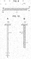
- a tension force is applied in a central axis direction of the wound body 211 to the spirally twisted fiber-shaped wound body 211, and as illustrated in Figs. 10A and 10B , the spirally twisted wound body 211 is longer than a wound body 211A in a state in which spiral twist is released.
- a diameter R 1 of the spirally twisted wound body 211 is smaller than a diameter R 0 of the wound body 211A in the state in which the spiral twist is released.
- the wound body 211 is similar to the wound body 11 of the first embodiment except the above-described points.
- the fiber-shaped wound body 211A is fabricated as in a manner similar to that in the first embodiment.
- the wound body 211A is twisted.
- the wound body 211A may be twisted while being pulled in a longitudinal direction thereof.
- the spirally twisted wound body 211 is obtained as illustrated in Fig. 10B .
- the actuator 210 according to the third embodiment is provided with the spirally twisted fiber-shaped wound body 211.
- the diameter R 1 of the spirally twisted wound body 211 is smaller than the diameter R 0 of the wound body 211A in the state in which the spiral twist is released. Therefore, since the elastomer layers 21A and 22A are further thinned, a driving voltage of the actuator 10 may be further reduced.
- An actuator 220 may be provided with a spirally wound fiber-shaped wound body 221 as illustrated in Fig. 11 .
- the actuator 220 having such a configuration may be used, for example, in a tactile sense presenting device and the like.
- the wound body 211 may also be obtained by spirally twisting any of the wound body 11 and the laminate in the variation of the first embodiment (variation 5), and the wound body 111 in the second embodiment and the variation thereof. Furthermore, a plurality of bundled wound bodies 11 or laminates (variation 5 of the first embodiment) may be twisted.
- the tactile sense presenting device is an example of a driving device, and is provided with an actuator array 311, a voltage source 312, and a control unit not illustrated. Note that, in this application example, a portion similar to that in the first embodiment is assigned with the same reference sign and the description thereof is omitted.
- the actuator array 311 is an example of a driving member, and is provided with a plurality of actuators 10 having a fiber shape.
- the plurality of actuators 10 is arranged in line such that axial directions of the respective actuators 10 are in the same direction, and peripheral surfaces of adjacent actuators 10 face each other.
- Terminals 13A and 13B are connected to the voltage source 312 via wiring 313A and wiring 313B, respectively.
- the voltage source 312 supplies a driving voltage of a predetermined frequency to each actuator 310 on the basis of a control signal from the control unit not illustrated.
- Figs. 13A and 13B An example of operation of the tactile sense presenting device having the above-described configuration is described with reference to Figs. 13A and 13B .
- Fig. 13A a case in which both ends of the actuator array 311 forming the actuator array 311 are supported by support bodies 314 is described.
- the actuator 10 When a driving voltage is applied to the actuator 10, as illustrated in Fig. 13B , the actuator 10 extends and bends. When the driving voltage applied to the actuator 10 is released, as illustrated in Fig. 13A , the actuator 10 contracts to return to its original length, and becomes linear.
- the actuator array 311 may be provided with any one of the actuator 10 according to the variation of the first embodiment, the actuator 110 according to the second embodiment and the variation thereof, and the actuator 210 according to the third embodiment and the variation thereof in place of the actuator 10 according to the first embodiment.
- the tactile sense presenting device is an example of a driving device, and is provided with an actuator array 411, a voltage source 412, and a control unit not illustrated. Note that, in this application example, a portion similar to that in the first embodiment is assigned with the same reference sign and the description thereof is omitted.
- the actuator array 411 is an example of a driving member, and is provided with a plurality of actuators 10 having a fiber shape, and the plurality of actuators 10 is two-dimensionally arranged in a mesh pattern.
- the actuator array 320 is provided with actuators 10 of a first group having a fiber shape, and actuators 10 of a second group having a fiber shape superimposed on the actuators 10 of the first group.
- the actuators 10 of the first group are arranged in line at a predetermined interval such that the longitudinal direction of the actuators 10 is in a first direction and peripheral surfaces of the adjacent actuators 10 face each other.
- the actuators 10 of the second group are arranged in line at a predetermined interval such that the longitudinal direction of the actuators 10 is in a second direction intersecting with (for example, orthogonal to) the first direction and the peripheral surfaces of the adjacent actuators 10 face each other.
- the terminals 13A and 13B of the actuators 10 of the first group are connected to the voltage source 412 via wiring 413A and wiring 413B, respectively.
- the terminals 13A and 13B of the actuators 10 of the second group are connected to the voltage source 412 via wiring 414A and wiring 414B, respectively.
- the voltage source 412 supplies a driving voltage of a predetermined frequency to each actuator 310 on the basis of a control signal from the control unit not illustrated.
- the actuator array 320 may be provided with any one of the actuator 10 according to the variation of the first embodiment, the actuator 110 according to the second embodiment and the variation thereof, and the actuator 210 according to the third embodiment and the variation thereof in place of the actuator 10 according to the first embodiment.
- the linear driving device is an example of a driving device, and is provided with an actuator group 511 having a columnar shape, a voltage source 512, and a control unit not illustrated. Note that, in this application example, a portion similar to that in the first embodiment is assigned with the same reference sign and the description thereof is omitted.
- the actuator group 511 is an example of a driving member, and is provided with a plurality of actuators 10 having a bar-shape, and the plurality of actuators 10 is bundled by a holding member not illustrated.
- a holding member for example, a shrinking ring-shaped member, a shrinking sticky tape, or a shrinking tubular member which houses the plurality of actuators 10 may be used.
- a shape of the tubular member is not particularly limited, but a cylindrical shape or a rectangular cylindrical shape may be exemplified.
- the terminals 13A and 13B are connected to the voltage source 512 via wiring 513A and wiring 513B, respectively.
- the voltage source 512 supplies a driving voltage to each actuator 310 on the basis of a control signal from the control unit not illustrated.
- the linear driving device may further be provided with a support body 514 which supports one end of the actuator group 511 and a columnar fixing member 515 fixed to the other end of the actuator group 511, as illustrated in Fig.16 .
- the linear driving device having the above-described configuration operates as follows. In other words, when a driving voltage is applied to the actuator 10, the actuator group 511 is extended. Furthermore, when the driving voltage applied to the actuator 10 is released, the actuator group 511 is contracted.
- the actuator group 511 may be provided with any one of the actuator 10 according to the variation of the first embodiment, the actuator 110 according to the second embodiment and the variation thereof, and the actuator 210 according to the third embodiment and the variation thereof in place of the actuator 10 according to the first embodiment.
- the joint driving device is an example of a driving device, and is provided with a columnar body 611, a pair of actuators 612A and 612B, a support body 613 which supports one end of the columnar body 611 and the actuators 612A and 612B, a rotating body 614 rotatably supported by the other end of the columnar body 611, a driving unit 615 supported by the rotating body 614, a voltage source 616, and a control unit not illustrated.
- a linear member 617 such as a wire is stretched around a peripheral surface of the rotating body 614.
- One end of the linear member 617 is connected to the other end of the actuator 612A, and the other end of the linear member 617 is connected to the other end of the actuator 612B.
- the rotating body 614 is rotatable via the linear member by expansion and contraction of the actuators 612A and 612B.
- the voltage source 616 is electrically connected to the actuators 612A and 612B via wiring 620, and supplies a driving voltage to the actuators 612A and 612B on the basis of a control signal from the control unit not illustrated.
- the actuators 612A and 612B are any one of the actuator 10 according to the first embodiment and the variation thereof, the actuator 110 according to the second embodiment and the variation thereof, and the actuator 210 according to the third embodiment and the variation thereof.
- the linear driving device having the above-described configuration operates as follows.
- the driving voltage is controlled to extend the actuator 612A and contract the actuator 612B
- the rotating body 614 rotates in a direction indicated by arrow 618A via the linear member 617.
- the driving unit 615 drives in a direction indicated by arrow 619A.
- the driving voltage is controlled to contract the actuator 612A and extend the actuator 612B
- the rotating body 614 rotates in a direction indicated by arrow 618B via the linear member 617.
- the driving unit 615 drives in a direction indicated by arrow 619B.
- the present technology may also adopt the following configurations.
Landscapes
- Physics & Mathematics (AREA)
- Engineering & Computer Science (AREA)
- Mechanical Engineering (AREA)
- General Physics & Mathematics (AREA)
- Spectroscopy & Molecular Physics (AREA)
- Laminated Bodies (AREA)
Abstract
Description
- The present technology relates to an actuator, a driving member, a tactile sense presenting device, and a driving device.
- In recent years, it is desired to make a dielectric elastomer actuator thin. For example,
Patent Document 1 discloses a technology of achieving a thin elastomer while controlling a movement direction thereof by applying pre-distortion to the elastomer. - Patent Document 1: PCT Japanese Translation Patent Publication No.
2003-506858 - An object of the present technology is to provide a thin actuator, a driving member provided with the same, a tactile sense presenting device, and a driving device.
- In order to solve the above-described problem, a first technology is an actuator including a laminate including an elastomer layer and an electrode, in which the laminate has a spiral or concentric shape, pre-distortion is applied to at least one member out of the elastomer layer and the electrode, and area distortion of the at least one member is 10% or larger.
- A second technology is a driving member including a plurality of the actuators.
- A third technology is a tactile sense presenting device including the actuator.
- A fourth technology is a driving device including the actuator.
- According to the present technology, a thin actuator may be realized. Note that, the effects herein described are not necessarily limited and may be any of the effects described in the present disclosure or other effects.
-
-
Fig. 1A is a perspective view illustrating an example of an appearance of an actuator according to a first embodiment of the present technology.Fig. 1B is a cross-sectional view taken along line IB-IB ofFig. 1A . -
Fig. 2A is a perspective view illustrating an example of an appearance of a wound body.Fig. 2B is an exploded perspective view illustrating an example of the wound body in a fully unwound state.Fig. 2C is an exploded perspective view illustrating an example of the wound body in a partially unwound state. -
Fig. 3A is an enlarged perspective view of one end face of the wound body.Fig. 3B is an enlarged perspective view of the other end face of the wound body. -
Figs. 4A, 4B, and 4C are perspective views illustrating variations of the wound body. -
Fig. 5A is a perspective view illustrating an example of an appearance of an actuator according to a second embodiment of the present technology.Fig. 5B is an enlarged plan view illustrating one end face of the actuator illustrated inFig. 5A. Fig. 5C is a cross-sectional view taken along line VC-VC ofFig. 5B . -
Fig. 6A is an exploded perspective view illustrating an example of the actuator in a fully unwound state.Fig. 6B is an exploded perspective view illustrating an example of the actuator in a partially unwound state. -
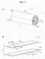
Fig. 7A is a perspective view illustrating a variation of the actuator.Fig. 7B is an exploded perspective view illustrating an example of the actuator in a fully unwound state. -
Fig. 8A is a perspective view illustrating a variation of the actuator.Fig. 8B is an exploded perspective view illustrating an example of the actuator in a fully unwound state. -
Fig. 9 is a plan view illustrating an example of a configuration of an actuator according to a third embodiment of the present technology. -
Figs. 10A and 10B are flowcharts for illustrating an example of a method of manufacturing the actuator according to the third embodiment of the present technology. -
Fig. 11 is a plan view illustrating a variation of the actuator. -
Fig. 12 is a schematic diagram illustrating an example of a configuration of a tactile sense presenting device as an application example. -
Figs. 13A and 13B are side views for illustrating an example of operation of the tactile sense presenting device. -
Fig. 14 is a schematic diagram illustrating another example of a configuration of a tactile sense presenting device as an application example. -
Fig. 15 is a schematic diagram illustrating an example of a configuration of a linear driving device as an application example. -
Fig. 16 is a perspective view illustrating another example of a configuration of a linear driving device as an application example. -
Fig. 17 is a side view illustrating an example of a configuration of a joint driving device. - Embodiments and application examples of the present technology are described in the following order.
- 1 First Embodiment (Example of Actuator)
- 2 Second Embodiment (Example of Actuator)
- 3 Third Embodiment (Example of Actuator)
- 4 Application Example (Example of Tactile Sense Presenting Device)
- 5 Application Example (Example of Tactile Sense Presenting Device)
- 6 Application Example (Example of Linear Driving Device)
- 7 Application Example (Example of Joint Driving Device)
- An
actuator 10 according to a first embodiment of the present technology is a so-called dielectric elastomer actuator (DEA) and is provided with, as illustrated inFigs. 1A and 1B , a substantiallycylindrical wound body 11, a disk-shaped extractingelectrode 12A provided so as to cover one end face 11SA of thewound body 11, and a disk-shaped extractingelectrode 12B provided so as to cover the other end face 11SB of thewound body 11.Terminals electrodes terminals wound body 11 may have a bar shape or may have a fiber shape. Note that,Figs. 1A and 1B illustrate an example in which thewound body 11 has a bar shape. - The
actuator 10 according to the first embodiment is provided on, for example, medical instruments such as artificial muscles or endoscopes, industrial instruments, antennas, electronic devices, tactile sense presenting devices, vibrating devices such as vibrators, acoustic transducers (such as speakers), pumps, valves, drones, fitting devices, sensors, rehabilitation instruments, robots, robot suits, micro devices, anti-shake modules or the like. Examples of the electronic devices include, but are not limited to, for example, personal computers, mobile devices, mobile phones, tablet computers, display devices, imaging devices, audio devices, game devices and the like. -
Fig. 2A illustrates an example of an appearance of thewound body 11.Fig. 2B illustrates an example of the wound body in a fully unwound state.Fig. 2C illustrates an example of the wound body in a partially unwound state. Thewound body 11 is a main body of theactuator 10 and is provided with anelectrode sheet 21 having an elongated shape and anelectrode sheet 22 having an elongated shape. - The
electrode sheet 21 is an example of a first laminate and is provided with an elastomer layer (dielectric layer) 21A having elasticity and anelectrode 21B having elasticity provided on one surface of theelastomer layer 21A. Theelastomer layer 21A and theelectrode 21B both have elongated rectangular shapes, and theelastomer layer 21A is slightly larger than theelectrode 21B. Theelectrode 21B is provided on the one surface of theelastomer layer 21A so that longitudinal directions of theelastomer layer 21A and theelectrode 21B coincide with each other. - The
electrode sheet 22 is an example of a second laminate and is provided with an elastomer layer (dielectric layer) 22A having elasticity and anelectrode 22B having elasticity provided on one surface of theelastomer layer 22A. Theelastomer layer 22A and theelectrode 22B both have elongated rectangular shapes, and theelastomer layer 22A is slightly larger than theelectrode 22B. Theelectrode 22B is provided on the one surface of theelastomer layer 22A so that longitudinal directions of theelastomer layer 21A and theelectrode 21B coincide with each other. - The
electrode sheets electrode sheets wound electrodes wound body 11. Specifically, theelectrode sheets electrode sheets electrode 22B, theelastomer layer 22A, theelectrode 21B, and theelastomer layer 21A are repeated in this order from the center toward the outer circumference of thewound body 11. - One long side of the
electrode 21B is located on an inner side of one long side of theelastomer layer 21A as illustrated inFigs. 2B and 2C , whereas the other long side of theelectrode 21B is overlapped with the other long side of theelastomer layer 21A. Furthermore, one long side of theelectrode 22B is overlapped with one long side of theelastomer layer 22A as illustrated inFigs. 2B and 2C , whereas the other long side of theelectrode 22B is located on an inner side of the other long side of theelastomer layer 22A. - The
electrode sheets electrode 22B is on a side of one end face 11SA of thewound body 11 and the other long side of theelectrode 21B is on a side of the other end face 11SB of thewound body 11. Therefore, as illustrated inFig. 3A , the one long side of theelectrode 22B is exposed from the one end face 11SA of thewound body 11, whereas the one long side of theelectrode 21B is not exposed. Furthermore, as illustrated inFig. 3B , the other long side of theelectrode 21B is exposed from the other end face 11SB of thewound body 11, whereas the other long side of theelectrode 22B is not exposed. - The long side of the
electrode 22B exposed from the one end face 11SA is in contact with one main surface of the extractingelectrode 12A. Furthermore, the long side of theelectrode 21B exposed from the other end face 11SB is in contact with one main surface of the extractingelectrode 12B. - Pre-distortion (that is, biaxial extension) is applied to the
electrode sheets 21 and 22 (that is, the elastomer layers 21A and 22A and theelectrodes wound body 11. Since the pre-distortion is applied to theelectrode sheets actuator 10 may be reduced. - A stress ratio (A:B) between a stress A in the axial direction 11DA and a stress B in the circumferential direction 11DB of the
electrode sheets electrode sheet - Area distortion of the
electrode sheets electrode sheets actuator 10 may be thinned. Furthermore, since the elastomer layers 21A and 22A may be thinned, the driving voltage of theactuator 10 may be reduced. - In order to suppress breakage of the
electrode sheets electrode sheets - The above-described area distortion of the
electrode sheets electrode sheets electrode sheets - The elastomer layers 21A and 22A are sheets having elasticity. An average thickness of the elastomer layers 21A and 22A in a pre-distorted state is preferably 10 µm or smaller, more preferably 5 µm or smaller, and still more preferably 3 µm or smaller from the viewpoint of reducing the driving voltage. In a case where the elastomer layers 21A and 22A are not pre-distorted (that is, not extended), it is difficult to make the average thickness of the elastomer layers 21A and
22A 10 µm or smaller. A lower limit value of the average thickness of the elastomer layers 21A and 22A in the pre-distorted state is not particularly limited, but is, for example, 300 nm or larger. - The average thickness of the elastomer layers 21A and 22A in the state in which the pre-distortion is released is preferably 40 µm or smaller, more preferably 20 µm or smaller, and still more preferably 12 µm or smaller from the viewpoint of reducing the driving voltage. A lower limit value of the average thickness of the elastomer layers 21A and 22A in the state in which the pre-distortion is released is not particularly limited, but is, for example, 1 µm or larger.
- The average thickness of the elastomer layers 21A and 22A is obtained as follows. First, the
wound body 11 is processed by a focused ion beam (FIB) method or the like to prepare a cross-section, and a cross-sectional image (hereinafter referred to as a "cross-sectional SEM image") is captured using a scanning electron microscope (SEM). Next, ten points are randomly selected from the elastomer layers 21A and 22A in the cross-sectional SEM image, the thickness of the elastomer layers 21A and 22A is measured at each point, and measured values are simply averaged (arithmetically averaged) to obtain the average thickness of the elastomer layers 21A and 22A. - A Young's modulus of the elastomer layers 21A and 22A is preferably 10 MPa or smaller, more preferably 0.05 MPa or larger and 10 MPa or smaller, and still more preferably 0.1 MPa or larger and 1 MPa or smaller. The above-described Young's modulus is a value measured in accordance with JIS K 6251:2010. Extension is easy when the Young's modulus is 10 MPa or smaller. On the other hand, handling is easily when the Young's modulus is 0.05 MPa or larger. Breaking distortion of the elastomer layers 21A and 22A is preferably 50% or larger, more preferably 100% or larger, still more preferably 150% or larger, and particularly preferably 200% or larger. When the breaking distortion is 50% or larger, an extension amount may be made larger. An upper limit value of the breaking distortion of the elastomer layers 21A and 22A is not particularly limited, but is, for example, 1200% or smaller. The breaking distortion of the elastomer layers 21A and 22A is the breaking distortion in the axial direction 11DA and the circumferential direction 11DB of the
wound body 11, and is measured, for example, in accordance with JIS K 6251:2010. - The elastomer layers 21A and 22A include, for example, an insulating elastomer as an insulating elastic material. The elastomer layers 21A and 22A may also include an additive as needed. The additive is, for example, at least one of a crosslinking agent, a plasticizer, an antiaging agent, a surfactant agent, a viscosity modifier, a reinforcing agent, a coloring agent or the like. The insulating elastomer includes, for example, at least one of acrylic rubber, silicone rubber, ethylene-propylene-diene terpolymer (EPDM), natural rubber (NR), butyl rubber (IIR), isoprene rubber (IR), acrylonitrile-butadiene copolymer rubber (NBR), hydrogenated-acrylonitrile-butadiene copolymer rubber (H-NBR), hydrin rubber, chloroprene rubber (CR), fluororubber, urethane rubber or the like.
- The
electrodes electrodes actuator 10 is driven, theelectrodes wound body 11 is extended, theelectrodes - The
electrodes electrodes - An average thickness of the
electrodes electrodes electrodes - The Young's modulus of the
electrodes electrodes electrodes electrodes wound body 11, and is measured, for example, in accordance with JIS K 6251:2010. - Volume resistivity of the
electrodes wound body 11 is preferably 10 MΩ.cm or smaller. As a result, also in a case where the distortion of 100% or larger is applied to thewound body 11, theelectrodes electrodes electrodes electrodes electrodes wound body 11 is greatly extended such that the pre-distortion of 50% or larger is applied. - The
electrodes electrodes electrodes - The conductive material is, for example, at least one of a conductive filler or a conductive polymer. A shape of the conductive filler may be, for example, a spherical shape, an ellipsoidal shape, a needle shape, a plate shape, a scale shape, a tubular shape, a wire shape, a bar shape (rod shape), a fiber shape, an irregularly shape and the like, but the shape is not particularly limited thereto. Note that, it is possible to use only the conductive filler of one shape, or combine the conductive fillers of two or more types of shapes to use.
- The conductive filler includes, for example, at least one of a carbon-based filler, a metal-based filler, a metal oxide-based filler, or a metal-coated filler. Here, it is defined that metal includes semi metal.
- The carbon-based filler includes, for example, at least one of carbon black (for example, Ketjen black, acetylene black and the like), porous carbon, carbon fiber (for example, PAN-based one, pitch-based one and the like), carbon nanofiber, fullerene, graphene, vapor grown carbon fiber (VGCF), carbon nanotube (for example, SWCNT, MWCNT and the like), carbon microcoil, or carbon nanohorn.
- The metal-based filler includes, for example, at least one of copper, silver, gold, platinum, palladium, nickel, tin, cobalt, rhodium, iridium, steel, ruthenium, osmium, manganese, molybdenum, tungsten, niobium, tantalum, titanium, bismuth, antimony, or lead.
- The metal oxide-based filler includes an indium tin oxide (ITO), a zinc oxide, an indium oxide, an antimony-added tin oxide, a fluorine-added tin oxide, an aluminum-added zinc oxide, a gallium-added zinc oxide, a silicon-added zinc oxide, zinc oxide-tin oxide, indium oxide-tin oxide, zinc oxide-indium oxide-magnesium oxide or the like, for example.
- The metal-coated filler is obtained by coating a base filler with metal. The base filler is, for example, mica, glass bead, glass fiber, carbon fibers, calcium carbonate, zinc oxide or titanium oxide. The metal coating the base filler includes, for example, at least one of Ni or Al.
- The conductive polymer is, for example, at least one of polyethylene dioxythiophene/polystyrene sulfonic acid (PEDOT/PSS), polyaniline, polyacetylene, or polypyrrole.
- The binder is preferably an elastomer. As the elastomer, one similar to that of the elastomer layers 21A and 22A may be exemplified. As the additive, one similar to that of the elastomer layers 21A and 22A may be exemplified.
- The
electrodes - Interfaces between the elastomer layers 21A and 22A and the
electrodes electrodes electrodes wound body 11 is greatly extended such that the pre-distortion of 50% or larger is applied. - In order to improve the adhesiveness of the interface, the
wound body 11 is preferably provided with at least one of (1) a silane coupling agent provided between the elastomer layers 21A and 22A and theelectrodes electrodes electrodes electrodes - A type of the silane coupling agent is not particularly limited, and known silane coupling agents may be used. Specific examples of the silane coupling agent include vinyltrichlorosilane, vinyltrimethoxysilane, vinyltriethoxysilane, 2-(3,4-epoxycyclohexyl)ethyltrimethoxysilane, 3-glycidoxypropyltrimethoxysilane, 3-glycidoxypropylmethyldiethoxysilane, 3-glycidoxypropyltriethoxysilane, p-styryltrimethoxysilane, 3-methacryloxypropylmethyldimethoxysilane, 3-methacryloxypropyltrimethoxysilane, 3-methacryloxypropylmethyldiethoxysilane, 3-methacryloxypropyltriethoxysilane, 3-acryloxypropyltrimethoxysilane, N-2-(aminoethyl)-3-aminopropylmethyldimethoxysilane, N-2-(aminoethyl)-3-aminopropyltrimethoxysilane, N-2-(aminoethyl)-3-aminopropyltriethoxysilane, 3-aminopropyltrimethoxysilane, 3-aminopropyltriethoxysilane, 3-triethoxysilyl-N-(1,3-dimethyl-butylidene)propylamine, N-phenyl-3-aminopropyltrimethoxysilane, N-(vinylbenzyl)-2-aminoethyl-3-aminopropyltrimethoxysilane hydrochloride, 3-ureidopropyltriethoxysilane, 3-chloropropyltrimethoxysilane, 3-mercaptopropylmethyldimethoxysilane, 3-mercaptopropyltrimethoxysilane, bis(triethoxysilylpropyl)tetrasulfide, 3-isocyanatopropyltriethoxysilane and the like.
- The extracting
electrodes electrodes electrodes wound body 11 in the radial direction, it is possible to suppress the extractingelectrodes - The extracting
electrodes electrodes electrodes - Next, an example of operation of the
actuator 10 according to the first embodiment of the present technology is described. - When a driving voltage is applied between the
electrodes electrodes electrodes - On the other hand, when the driving voltage applied between the
electrodes electrodes - Next, an example of a method of manufacturing the
actuator 10 according to the first embodiment of the present technology is described. - Elastomer layer forming paint is prepared by adding the elastomer to a solvent to disperse. At least one of resin materials or additives other than the elastomer may be further added to the solvent as needed. For example, in order to improve applicability of the elastomer layer forming paint to a base material (peeling base material) and pot life, the additive such as a surfactant agent, a viscosity modifier, and dispersant may be added as needed. As a dispersing method, it is preferable to use stirring, ultrasonic dispersion, bead dispersion, kneading, homogenizer treatment and the like.
- The solvent is not particularly limited as long as this may disperse the elastomer. For example, water, ethanol, methyl ethyl ketone, isopropanol alcohol, acetone, anone (cyclohexanone, cyclopentanone), hydrocarbon (hexane), amide (DMF), sulfide (DMSO), butyl cellosolve, butyl triglycol, propylene glycol monomethyl ether, propylene glycol monoethyl ether, ethylene glycol monoethyl ether, ethylene glycol monopropyl ether, ethylene glycol monoisopropyl ether, diethylene glycol monobutyl ether, diethylene glycol monoethyl ether, diethylene glycol monomethyl ether, diethylene glycol diethyl ether, dipropylene glycol monomethyl ether, tripropylene glycol monomethyl ether, propylene glycol monobutyl ether, propylene glycol isopropyl ether, dipropylene glycol isopropyl ether, tripropylene glycol isopropyl ether, methyl glycol, terpineol, and butyl carbitol acetate may be used.
- A conductive paint which is an electrode forming paint is prepared by adding a conductive material to a solvent to disperse. At least one of binders or additives may be further added to the solvent as needed. For example, in order to improve applicability of the conductive paint to the elastomer layers 21A and 22A and pot life, additives such as a surfactant agent, a viscosity modifier, and dispersant may be added as needed. The conductive paint may be a conductive ink or a conductive paste. As a dispersing method, one similar to that at the preparing step of the elastomer layer forming paint may be exemplified. Furthermore, the solvent is not particularly limited as long as this may disperse the conductive material. For example, one similar to that at the preparing step of the elastomer layer forming paint may be exemplified.
- The
electrode sheet 21 is fabricated as follows. First, a base material is prepared, one surface of the base material is subjected to a peeling treatment as needed. As the base material, an inorganic base material may be used, or a plastic base material may be used. Furthermore, as the base material, a plate-shaped one may be used and a sheet-shaped one may be used. - Next, the elastomer layer forming paint is applied to the one surface of the base material to form a coating film having an elongated rectangular shape. Here, application includes printing. As an applying method, for example, a microgravure coating method, a wire bar coating method, a direct gravure coating method, a die coating method, a dip method, a spray coating method, a reverse roll coating method, a curtain coating method, a comma coating method, a knife coating method, a spin coating method, an ink jet printing method, a relief printing method, an offset printing method, a gravure printing method, an intaglio printing method, a rubber plate printing method, a screen printing method and the like may be used, but this is not particularly limited thereto. Subsequently, the coating film formed on the one surface of the base material is dried. A drying condition is not particularly limited, and may be either natural drying or heat drying. As a result, the
elastomer layer 21A is formed on the one surface of the base material. Thereafter, one surface of theelastomer layer 21A may be treated to improve the adhesiveness as described above as needed. - Next, the conductive paint is applied to the one surface of the
elastomer layer 21A to form a coating film having an elongated rectangular shape. At that time, the coating film is formed such that one long side of the coating film is located on an inner side of one long side of theelastomer layer 21A, whereas the other long side of the coating film overlaps with the other long side of theelastomer layer 21A. As an applying method, a method similar to that when applying the elastomer layer forming paint may be exemplified. - Subsequently, the coating film formed on the one surface of the
elastomer layer 21A is dried to form theelectrode 21B. A drying condition is not particularly limited, and may be either natural drying or heat drying. Theelectrode sheet 21 is fabricated as described above. - The
electrode sheet 22 is fabricated in a manner similar to that of theelectrode sheet 21. - As illustrated in
Fig. 2B , a laminate having an elongated rectangular shape is obtained by placing theelectrode sheet 22 on theelectrode sheet 21 so as to overlap the respective sides of the elastomer layers 21A and 22A and interpose theelastomer layer 22A between theelectrodes electrode sheets electrode 22B is exposed from the end face on a side of one long side of the laminate, and the other long side of theelectrode 21B is exposed from the end face on a side of the other long side of the laminate. - As illustrated in
Fig. 2C , by winding the obtained laminate in a longitudinal direction while biaxially extending the laminate in a width direction (axial direction) 11DA and a longitudinal direction (circumferential direction) 11DB of the laminate, so that thewound body 11 illustrated toFig. 2A is obtained. - Subsequently, the extracting
electrode 12A is fixed to the one end face 11SA of thewound body 11 by adhesion or welding, and the extractingelectrode 12B is fixed to the other end face 11SB by adhesion or welding. In this manner, theactuator 10 illustrated inFig. 1A is obtained. - The
actuator 10 according to the first embodiment is provided with theelectrode sheet 21 as the first laminate and theelectrode sheet 22 as the second laminate, theelectrode sheets electrode sheets electrode sheets actuator 10 may be thinned. Furthermore, since the elastomer layers 21A and 22A may be thinned, the driving voltage of theactuator 10 may be reduced. - In a case where the stress ratio (A:B) between the stress A in the axial direction 11DA and the stress B in the circumferential direction 11DB of the
electrode sheets wound body 11 in the pre-distorted state (that is, the extended state) without the support member. Therefore, a structure of anentire actuator 10 may be simplified. Furthermore, since a part of force generated by theactuator 10 is not consumed due to an influence of rigidity of the support member, a force which may be extracted to the outside may be increased. - At least one of the
electrode 21B or theelastomer layer 22A adjacent in thewound body 11 may have stickiness. In this case, it is possible to suppress one end on an outer circumferential side of theelectrode sheet 21 from peeling due to a tension force caused by extension. At least one of theelectrode 22B or theelastomer layer 21A adjacent in thewound body 11 may have a sticky surface. In this case, it is possible to suppress one end on an outer circumferential side of theelectrode sheet 22 from peeling due to a tension force caused by extension. - Furthermore, an end on the outer circumferential side of at least one of the
electrode 21B or theelastomer layer 22A adjacent in thewound body 11 may have stickiness. An end on the outer circumferential side of at least one of theelectrode 22B or theelastomer layer 21A adjacent in thewound body 11 may have stickiness. - The
actuator 10 may further be provided with one or two or more ring-shaped windingstop members 14 for stop winding the wound body 11 (that is, thewound electrode sheets 21 and 22) as illustrated inFig. 4A . In this case, it is possible to suppress one ends on the outer circumferential side of theelectrode sheets stop member 14 has elasticity. This is because, when theactuator 10 is driven, the windingstop member 14 may be deformed following the contraction of thewound body 11, so that positional deviation of the windingstop member 14 may be suppressed. - As the winding
stop member 14, there may be, for example, a ring-shaped member having elasticity, a sticky tape having elasticity and the like. Note that, in a case of using the sticky tape as the windingstop member 14, the windingstop member 14 does not have to have a ring shape. - The
actuator 10 may further be provided with acylindrical housing member 15 for housing thewound body 11 as illustrated inFig. 4B . In this case, it is possible to suppress one ends on the outer circumferential side of theelectrode sheets housing member 15 preferably has elasticity. This is because, when theactuator 10 is driven, thehousing member 15 may be deformed following the contraction of thewound body 11, so that thehousing member 15 may be suppressed from being detached from thewound body 11. - As illustrated in
Fig. 4C , one end on the outer circumferential side of the spirallywound electrode sheets wound body 11 by an adhesive 16 to stop winding. Note that, two or more of the configurations of the first to fourth variations may be combined. - A main body of the
actuator 10 may be provided with a laminate including a plurality of concentric electrodes and a plurality of concentric elastomer layers in which the electrodes and the elastomers are alternately laminated in place of thewound body 11. - The
wound body 11 may be formed by winding one laminate sheet provided with theelastomer layer 21A, theelectrode 21B provided on one surface of theelastomer layer 21A, theelastomer layer 22A provided on one surface of theelectrode 21B, and theelectrode 22B provided on one surface of theelastomer layer 22A. - The
electrodes electrodes wound body 11. Furthermore, the plurality ofelectrodes - At least one of the elastomer layers 21A and 22A or the
electrodes - In the first embodiment, the configuration in which the
wound body 11 has a substantially cylindrical shape is described as an example, but thewound body 11 may also have a substantially prismatic shape. Furthermore, thewound body 11 may also have a tubular shape such as a substantially cylindrical shape or a substantially rectangular cylindrical shape. In this case, a support member such as a coil spring may be provided in a hollow internal space. Furthermore, the hollow internal space may be filled with liquid or solid in place of gas. Here, the liquid is, for example, water, saline solution or the like. Furthermore, the solid is, for example, a sol, a gel or the like. - In the first embodiment, the configuration in which the pre-distortion is applied to all of the
electrode sheets elastomer layer 21A, theelectrode 21B, theelastomer layer 22A, and theelectrode 22B is described; however, it is also possible that the pre-distortion is applied to at least one member out of theelastomer layer 21A and theelectrode 21B, and the pre-distortion is applied to at least one member out of theelastomer layer 22A and theelectrode 22B. Furthermore, it is possible that the pre-distortion is applied to at least one member out of theelastomer layer 21A, theelectrode 21B, theelastomer layer 22A, and theelectrode 22B. In a case of the above-described configuration, the area distortion of at least one member to which the pre-distortion is applied is 10% or larger, preferably 30% or larger, more preferably 50% or larger, still more preferably 70% or larger, and particularly preferably 100% or larger. Furthermore, the stress ratio (A:B) between the stress A in the axial direction 11DA and the stress B in the circumferential direction 11DB of theelectrode sheets - Hereinafter, an example of a configuration of an
actuator 110 according to a second embodiment of the present technology is described with reference toFigs. 5A to 5C ,6A, and 6B . Theactuator 110 is provided with a substantiallycylindrical wound body 111, an extractingelectrode 112A extracted from one end face 111SA of thewound body 111, and an extractingelectrode 112B extracted from the other end face 111SB of the wound body. Note that, in the second embodiment, a portion similar to that in the first embodiment is assigned with the same reference sign and the description thereof is omitted. - The
wound body 111 is a main body of theactuator 110, and is provided with anelongated electrode sheet 121 and anelongated electrode sheet 122. - The
electrode sheet 121 is provided with an elastomer layer (dielectric layer) 21A and anelectrode 121B provided on one surface of theelastomer layer 21A and having elasticity. Theelectrode 21B includes a rectangularmain body portion 121C and anextended portion 121D extended from a long side on a side of the one end face 111SA of both long sides of themain body portion 121C. Theelectrode 121B is provided on the one surface of theelastomer layer 21A so that longitudinal directions of theelastomer layer 21A and themain body portion 121C coincide with each other. Themain body portion 121C is slightly smaller than theelastomer layer 21A, and a peripheral edge (that is, both end sides and both long sides) of theelectrode 121B is located on an inner side of a peripheral edge (that is, both end sides and both long sides) of theelastomer layer 21A as illustrated inFigs. 6A and 6B . - The
electrode sheet 122 is provided with an elastomer layer (dielectric layer) 22A and anelectrode 122B provided on one surface of theelastomer layer 22A and having elasticity. Theelectrode 122B includes a rectangularmain body portion 122C and anextended portion 122D extended from a long side on a side of the other end face 111SB of both long sides of themain body portion 122C. Theelectrode 122B is provided on the one surface of theelastomer layer 22A so that longitudinal directions of theelastomer layer 22A and themain body portion 122C coincide with each other. Themain body portion 122C is slightly smaller than theelastomer layer 21A, and a peripheral edge (that is, both end sides and both long sides) of theelectrode 122B is located on an inner side of a peripheral edge (that is, both end sides and both long sides) of theelastomer layer 22A as illustrated inFigs. 6A and 6B . - The extracting
electrodes extended portions extended portions electrode sheets main body portions extended portions electrode sheets extended portions electrode sheets electrode sheets electrodes electrodes wound body 111 closer to the cylindrical shape and obtain ahigher performance actuator 110, as described above, theextended portions electrodes 121A and 121B. - In the
actuator 110 according to the second embodiment, both the long sides of themain body portions electrodes electrodes 121A and 122B from exposing from the end faces 111SA and 111SB. Therefore, since it is possible to suppress theelectrodes 121A and 122B from short-circuiting at the end faces 111SA and 111SB, safety of theactuator 110 may be improved. - As illustrated in
Fig. 7A , both the extractingelectrodes wound body 111. In this case, as illustrated inFig. 7B , theextended portions main body portions extended portion 121D is preferably provided on a position on one end of the long side on the side of the one end face 111SA, and theextended portion 122D is preferably provided on a position on the other end of the long side on the side of the one end face 111SA. This is because the shape of thewound body 111 may be made more cylindrical, and ahigher performance actuator 110 may be obtained. - As illustrated in
Fig. 8A , the extractingelectrodes wound body 111. By extracting the extractingelectrodes wound body 111 may be made more closer to a cylindrical shape, and theactuator 110 with higher performance may be obtained. - In a case of the above-described configuration, the
extended portions main body portions Fig. 8B . Furthermore, it is preferable that theextended portion 121D is provided on a position on one end of the short side on the outer circumferential side, and theextended portion 121D is provided on the other end of the short side on the outermost circumferential side. This is because contact between the extractingelectrodes - An
actuator 210 according to a third embodiment of the present technology is different from theactuator 10 according to the first embodiment in including a spirally twisted fiber-shapedwound body 211 as illustrated inFig. 9 . Note that, in the third embodiment, a portion similar to that in the first embodiment is assigned with the same reference sign and the description thereof is omitted. - A tension force is applied in a central axis direction of the
wound body 211 to the spirally twisted fiber-shapedwound body 211, and as illustrated inFigs. 10A and 10B , the spirally twistedwound body 211 is longer than awound body 211A in a state in which spiral twist is released. In other words, a diameter R1 of the spirally twistedwound body 211 is smaller than a diameter R0 of thewound body 211A in the state in which the spiral twist is released. Thewound body 211 is similar to thewound body 11 of the first embodiment except the above-described points. - Next, an example of a method of manufacturing the
actuator 210 according to the third embodiment of the present technology is described. First, the fiber-shapedwound body 211A is fabricated as in a manner similar to that in the first embodiment. Next, as illustrated inFig. 10A , after fixing one end of thewound body 211A to a fixingmember 212, thewound body 211A is twisted. At that time, thewound body 211A may be twisted while being pulled in a longitudinal direction thereof. As described above, the spirally twistedwound body 211 is obtained as illustrated inFig. 10B . - The
actuator 210 according to the third embodiment is provided with the spirally twisted fiber-shapedwound body 211. The diameter R1 of the spirally twistedwound body 211 is smaller than the diameter R0 of thewound body 211A in the state in which the spiral twist is released. Therefore, since the elastomer layers 21A and 22A are further thinned, a driving voltage of theactuator 10 may be further reduced. - An
actuator 220 may be provided with a spirally wound fiber-shapedwound body 221 as illustrated inFig. 11 . Theactuator 220 having such a configuration may be used, for example, in a tactile sense presenting device and the like. - The
wound body 211 may also be obtained by spirally twisting any of thewound body 11 and the laminate in the variation of the first embodiment (variation 5), and thewound body 111 in the second embodiment and the variation thereof. Furthermore, a plurality of bundledwound bodies 11 or laminates (variation 5 of the first embodiment) may be twisted. - An example in which the present technology is applied to a tactile sense presenting device is described with reference to
Fig. 12 . The tactile sense presenting device is an example of a driving device, and is provided with anactuator array 311, avoltage source 312, and a control unit not illustrated. Note that, in this application example, a portion similar to that in the first embodiment is assigned with the same reference sign and the description thereof is omitted. - The
actuator array 311 is an example of a driving member, and is provided with a plurality ofactuators 10 having a fiber shape. The plurality ofactuators 10 is arranged in line such that axial directions of therespective actuators 10 are in the same direction, and peripheral surfaces ofadjacent actuators 10 face each other.Terminals voltage source 312 viawiring 313A andwiring 313B, respectively. Thevoltage source 312 supplies a driving voltage of a predetermined frequency to each actuator 310 on the basis of a control signal from the control unit not illustrated. - An example of operation of the tactile sense presenting device having the above-described configuration is described with reference to
Figs. 13A and 13B . Here, as illustrated inFig. 13A , a case in which both ends of theactuator array 311 forming theactuator array 311 are supported bysupport bodies 314 is described. - When a driving voltage is applied to the
actuator 10, as illustrated inFig. 13B , theactuator 10 extends and bends. When the driving voltage applied to theactuator 10 is released, as illustrated inFig. 13A , theactuator 10 contracts to return to its original length, and becomes linear. - The
actuator array 311 may be provided with any one of theactuator 10 according to the variation of the first embodiment, theactuator 110 according to the second embodiment and the variation thereof, and theactuator 210 according to the third embodiment and the variation thereof in place of theactuator 10 according to the first embodiment. - Another example in which the present technology is applied to a tactile sense presenting device is described with reference to
Fig. 14 . The tactile sense presenting device is an example of a driving device, and is provided with anactuator array 411, avoltage source 412, and a control unit not illustrated. Note that, in this application example, a portion similar to that in the first embodiment is assigned with the same reference sign and the description thereof is omitted. - The
actuator array 411 is an example of a driving member, and is provided with a plurality ofactuators 10 having a fiber shape, and the plurality ofactuators 10 is two-dimensionally arranged in a mesh pattern. Specifically, the actuator array 320 is provided withactuators 10 of a first group having a fiber shape, andactuators 10 of a second group having a fiber shape superimposed on theactuators 10 of the first group. - The
actuators 10 of the first group are arranged in line at a predetermined interval such that the longitudinal direction of theactuators 10 is in a first direction and peripheral surfaces of theadjacent actuators 10 face each other. Theactuators 10 of the second group are arranged in line at a predetermined interval such that the longitudinal direction of theactuators 10 is in a second direction intersecting with (for example, orthogonal to) the first direction and the peripheral surfaces of theadjacent actuators 10 face each other. - The
terminals actuators 10 of the first group are connected to thevoltage source 412 viawiring 413A andwiring 413B, respectively. Theterminals actuators 10 of the second group are connected to thevoltage source 412 viawiring 414A andwiring 414B, respectively. - The
voltage source 412 supplies a driving voltage of a predetermined frequency to each actuator 310 on the basis of a control signal from the control unit not illustrated. - The actuator array 320 may be provided with any one of the
actuator 10 according to the variation of the first embodiment, theactuator 110 according to the second embodiment and the variation thereof, and theactuator 210 according to the third embodiment and the variation thereof in place of theactuator 10 according to the first embodiment. - An example in which the present technology is applied to a linear driving device is described with reference to
Fig. 15 . The linear driving device is an example of a driving device, and is provided with anactuator group 511 having a columnar shape, avoltage source 512, and a control unit not illustrated. Note that, in this application example, a portion similar to that in the first embodiment is assigned with the same reference sign and the description thereof is omitted. - The
actuator group 511 is an example of a driving member, and is provided with a plurality ofactuators 10 having a bar-shape, and the plurality ofactuators 10 is bundled by a holding member not illustrated. As the holding member, for example, a shrinking ring-shaped member, a shrinking sticky tape, or a shrinking tubular member which houses the plurality ofactuators 10 may be used. A shape of the tubular member is not particularly limited, but a cylindrical shape or a rectangular cylindrical shape may be exemplified. - The
terminals voltage source 512 viawiring 513A andwiring 513B, respectively. Thevoltage source 512 supplies a driving voltage to each actuator 310 on the basis of a control signal from the control unit not illustrated. - The linear driving device may further be provided with a
support body 514 which supports one end of theactuator group 511 and acolumnar fixing member 515 fixed to the other end of theactuator group 511, as illustrated inFig.16 . - The linear driving device having the above-described configuration operates as follows. In other words, when a driving voltage is applied to the
actuator 10, theactuator group 511 is extended. Furthermore, when the driving voltage applied to theactuator 10 is released, theactuator group 511 is contracted. - The
actuator group 511 may be provided with any one of theactuator 10 according to the variation of the first embodiment, theactuator 110 according to the second embodiment and the variation thereof, and theactuator 210 according to the third embodiment and the variation thereof in place of theactuator 10 according to the first embodiment. - An example in which the present technology is applied to a joint driving device is described with reference to
Fig. 17 . The joint driving device is an example of a driving device, and is provided with acolumnar body 611, a pair ofactuators support body 613 which supports one end of thecolumnar body 611 and theactuators rotating body 614 rotatably supported by the other end of thecolumnar body 611, adriving unit 615 supported by therotating body 614, avoltage source 616, and a control unit not illustrated. - A
linear member 617 such as a wire is stretched around a peripheral surface of therotating body 614. One end of thelinear member 617 is connected to the other end of theactuator 612A, and the other end of thelinear member 617 is connected to the other end of theactuator 612B. Therotating body 614 is rotatable via the linear member by expansion and contraction of theactuators voltage source 616 is electrically connected to theactuators wiring 620, and supplies a driving voltage to theactuators - The
actuators actuator 10 according to the first embodiment and the variation thereof, theactuator 110 according to the second embodiment and the variation thereof, and theactuator 210 according to the third embodiment and the variation thereof. - The linear driving device having the above-described configuration operates as follows. In other words, when the driving voltage is controlled to extend the
actuator 612A and contract theactuator 612B, therotating body 614 rotates in a direction indicated byarrow 618A via thelinear member 617. As a result, the drivingunit 615 drives in a direction indicated byarrow 619A. On the other hand, when the driving voltage is controlled to contract theactuator 612A and extend theactuator 612B, therotating body 614 rotates in a direction indicated byarrow 618B via thelinear member 617. As a result, the drivingunit 615 drives in a direction indicated byarrow 619B. - Although the embodiments and the application examples thereof of the present technology are specifically described above, the present technology is not limited to the above-described embodiments and application examples and various modifications based on the technical idea of the present technology may be made.
- For example, the configuration, method, step, shape, material, numerical value and the like described in the above-described embodiments and application examples are merely examples, and the configuration, method, step, shape, material, numerical value and the like different from those may also be used as needed.
- Furthermore, the configuration, method, step, shape, material, numerical value and the like of the above-described embodiments and application examples thereof may be combined with one another within the gist of the present technology.
- Furthermore, the present technology may also adopt the following configurations.
- (1) An actuator including:
- a laminate including an elastomer layer and an electrode,
- in which the laminate has a spiral or concentric shape,
- pre-distortion is applied to at least one member out of the elastomer layer and the electrode, and
- area distortion of the at least one member is 10% or larger.
- (2) The actuator according to (1), in which a stress ratio (A:B) between a stress A in an axial direction and a stress B in a circumferential direction of the laminate is 1:2.
- (3) The actuator according to (1) or (2), in which the area distortion of the at least one member is 50% or larger.
- (4) The actuator according to any one of (1) to (3), in which the pre-distortion is applied in an axial direction and a circumferential direction of the laminate.
- (5) The actuator according to (4), in which a contraction force in the axial direction and a contraction force in the circumferential direction of the laminate are balanced.
- (6) The actuator according to any one of (1) to (5),
in which a Young's modulus of the elastomer layer is 10 MPa or smaller, and
breaking distortion of the elastomer layer is 50% or larger. - (7) The actuator according to any one of (1) to (6), in which at least one member out of the elastomer layer and the electrode has a multilayer structure.
- (8) The actuator according to (7), in which a surface layer of the member having the multilayer structure has stickiness.
- (9) The actuator according to any one of (1) to (7), in which at least one member out of the elastomer layer and the electrode has a sticky surface.
- (10) The actuator according to any one of (1) to (9), further including:
a winding stop member which stops winding the laminate having a spiral shape. - (11) The actuator according to any one of (1) to (10), further including:
a tubular housing member which houses the laminate having a spiral shape. - (12) The actuator according to any one of (1) to (11), in which one end on an outermost circumferential side of the laminate having a spiral shape is stopped winding by adhesion.
- (13) The actuator according to any one of (1) to (12), in which the actuator is spirally twisted.
- (14) The actuator according to any one of (1) to (13), in which the actuator has a fiber shape.
- (15) A driving member including: a plurality of the actuators according to any one of (1) to (14).
- (16) The driving member according to (15), in which the plurality of actuators is bundled.
- (17) The driving member according to (15), in which the plurality of actuators is arranged in line such that axial directions of the plurality of actuators are in a same direction, and peripheral surfaces of adjacent actuators face each other.
- (18) The driving member according to (15), in which the plurality of actuators is arranged in a mesh pattern.
- (19) A tactile sense presenting device including: the actuator according to any one of (1) to (14).
- (20) A driving device including: the actuator according to any one of (1) to (14).
-
- 10, 110, 210, 220
- Actuator
- 11, 111, 211, 221
- Wound body (actuator main body)
- 11SA, 11SB, 111SA, 111SB
- End face
- 11DA
- Axial direction
- 11DB
- Circumferential direction
- 12A, 12B, 112A, 112B
- Extracting electrode
- 13A, 13B
- Terminal
- 14
- Winding stop member
- 15
- Housing member
- 16
- Adhesive
- 21, 22, 121, 122
- Electrode sheet
- 21A, 22A
- Elastomer layer
- 21B, 22B, 121B, 122B
- Electrode
- 121C, 122C
- Main body portion
- 121D, 122D
- Extended portion
- 311, 411
- Actuator array
- 312, 412, 512, 616
- Voltage source
- 511
- Actuator group
Claims (20)
- An actuator comprising:a laminate including an elastomer layer and an electrode,wherein the laminate has a spiral or concentric shape,pre-distortion is applied to at least one member out of the elastomer layer and the electrode, andarea distortion of the at least one member is 10% or larger.
- The actuator according to claim 1, wherein a stress ratio (A:B) between a stress A in an axial direction and a stress B in a circumferential direction of the laminate is 1:2.
- The actuator according to claim 1, wherein the area distortion of the at least one member is 50% or larger.
- The actuator according to claim 1, wherein the pre-distortion is applied in an axial direction and a circumferential direction of the laminate.
- The actuator according to claim 4, wherein a contraction force in the axial direction and a contraction force in the circumferential direction of the laminate are balanced.
- The actuator according to claim 1,
wherein a Young's modulus of the elastomer layer is 10 MPa or smaller, and
breaking distortion of the elastomer layer is 50% or larger. - The actuator according to claim 1, wherein at least one member out of the elastomer layer and the electrode has a multilayer structure.
- The actuator according to claim 7, wherein a surface layer of the member having the multilayer structure has stickiness.
- The actuator according to claim 1, wherein at least one member out of the elastomer layer and the electrode has a sticky surface.
- The actuator according to claim 1, further comprising:
a winding stop member which stops winding the laminate having a spiral shape. - The actuator according to claim 1, further comprising:
a tubular housing member which houses the laminate having a spiral shape. - The actuator according to claim 1, wherein one end on an outermost circumferential side of the laminate having a spiral shape is stopped winding by adhesion.
- The actuator according to claim 1, wherein the actuator is spirally twisted.
- The actuator according to claim 1, wherein the actuator has a fiber shape.
- A driving member comprising: a plurality of the actuators according to claim 1.
- The driving member according to claim 15, wherein the plurality of actuators is bundled.
- The driving member according to claim 15, wherein the plurality of actuators is arranged in line such that axial directions of the plurality of actuators are in a same direction, and peripheral surfaces of adjacent actuators face each other.
- The driving member according to claim 15, wherein the plurality of actuators is arranged in a mesh pattern.
- A tactile sense presenting device comprising: the actuator according to claim 1.
- A driving device comprising: the actuator according to claim 1.
Applications Claiming Priority (2)
| Application Number | Priority Date | Filing Date | Title |
|---|---|---|---|
| JP2017093772 | 2017-05-10 | ||
| PCT/JP2018/017547 WO2018207707A1 (en) | 2017-05-10 | 2018-05-02 | Actuator, drive member, haptic device, and drive device |
Publications (2)
| Publication Number | Publication Date |
|---|---|
| EP3624328A1 true EP3624328A1 (en) | 2020-03-18 |
| EP3624328A4 EP3624328A4 (en) | 2020-05-13 |
Family
ID=64105350
Family Applications (1)
| Application Number | Title | Priority Date | Filing Date |
|---|---|---|---|
| EP18799225.0A Withdrawn EP3624328A4 (en) | 2017-05-10 | 2018-05-02 | ACTUATOR, DRIVE, HAPTIC DEVICE AND DRIVE |
Country Status (5)
| Country | Link |
|---|---|
| US (1) | US11433425B2 (en) |
| EP (1) | EP3624328A4 (en) |
| JP (1) | JP7205467B2 (en) |
| CN (1) | CN110603727B (en) |
| WO (1) | WO2018207707A1 (en) |
Families Citing this family (6)
| Publication number | Priority date | Publication date | Assignee | Title |
|---|---|---|---|---|
| CN113994585A (en) * | 2019-06-18 | 2022-01-28 | Strawb股份有限公司 | Electrostatic Actuator |
| CN110932595B (en) * | 2019-12-06 | 2026-02-27 | 浙江清华柔性电子技术研究院 | Flexible radial actuator and flexible radial drive system based on dielectric elastomer |
| CN113199844B (en) * | 2021-05-11 | 2022-12-16 | 浙江大学 | A kind of anisotropic dielectric elastomer fiber driver and its preparation method |
| DE102022104179B4 (en) | 2022-02-22 | 2024-06-13 | Technische Universität Dresden, Körperschaft des öffentlichen Rechts | Loudspeakers and procedures |
| WO2024075564A1 (en) * | 2022-10-03 | 2024-04-11 | ソニーグループ株式会社 | Dielectric elastomer actuator, transducer, device, information processing system, and method of producing dielectric elastomer actuator |
| US20260123286A1 (en) * | 2022-10-03 | 2026-04-30 | Sony Group Corporation | Method for manufacturing dielectric elastomer actuator, dielectric elastomer actuator, apparatus, and information processing system |
Family Cites Families (14)
| Publication number | Priority date | Publication date | Assignee | Title |
|---|---|---|---|---|
| ES2394160T3 (en) | 1999-07-20 | 2013-01-22 | Sri International | Electroactive polymers |
| US7233097B2 (en) * | 2001-05-22 | 2007-06-19 | Sri International | Rolled electroactive polymers |
| DE602004029989D1 (en) * | 2003-03-03 | 2010-12-23 | Stanford Res Inst Int | INVOLVED ELECTROACTIVE POLYMERS |
| US7038357B2 (en) * | 2003-08-21 | 2006-05-02 | Engineering Services Inc. | Stretched rolled electroactive polymer transducers and method of producing same |
| US7834527B2 (en) | 2005-05-05 | 2010-11-16 | SmartMotion Technologies, Inc. | Dielectric elastomer fiber transducers |
| CA2613532A1 (en) * | 2005-06-30 | 2007-01-11 | Victhom Human Bionics Inc. | Dielectric polymer actuator |
| ES2370178T3 (en) | 2006-08-17 | 2011-12-13 | Koninklijke Philips Electronics N.V. | PRESSURE ACTUATOR. |
| JP4922879B2 (en) | 2007-03-30 | 2012-04-25 | 東海ゴム工業株式会社 | Actuator |
| EP2406699A1 (en) | 2009-03-10 | 2012-01-18 | Bayer MaterialScience AG | Electroactive polymer transducers for tactile feedback devices |
| US9662516B2 (en) | 2011-01-28 | 2017-05-30 | W. L. Gore & Associates Gmbh | Laminar structure providing adaptive thermal insulation |
| TW201429147A (en) * | 2012-08-16 | 2014-07-16 | 拜耳智慧財產有限公司 | Electrical interconnect terminals for rolled dielectric elastomer transducers |
| KR102143352B1 (en) | 2013-12-13 | 2020-08-11 | 엘지디스플레이 주식회사 | Monolithic haptic type touch screen, manufacturing method thereof and display device includes of the same |
| EP3148482A4 (en) * | 2014-06-02 | 2018-02-21 | Amaranth Medical Pte | Bioabsorbable stents |
| KR102123170B1 (en) * | 2015-12-25 | 2020-06-26 | 미쯔이가가꾸가부시끼가이샤 | Piezoelectric substrate, piezoelectric fabric, piezoelectric knitted fabric, piezoelectric device, force sensor, actuator and biometric information acquisition device |
-
2018
- 2018-05-02 WO PCT/JP2018/017547 patent/WO2018207707A1/en not_active Ceased
- 2018-05-02 JP JP2019517597A patent/JP7205467B2/en active Active
- 2018-05-02 EP EP18799225.0A patent/EP3624328A4/en not_active Withdrawn
- 2018-05-02 CN CN201880029275.4A patent/CN110603727B/en not_active Expired - Fee Related
- 2018-05-02 US US16/612,281 patent/US11433425B2/en active Active
Also Published As
| Publication number | Publication date |
|---|---|
| CN110603727A (en) | 2019-12-20 |
| EP3624328A4 (en) | 2020-05-13 |
| JPWO2018207707A1 (en) | 2020-03-12 |
| CN110603727B (en) | 2023-04-04 |
| US20210146401A1 (en) | 2021-05-20 |
| WO2018207707A1 (en) | 2018-11-15 |
| JP7205467B2 (en) | 2023-01-17 |
| US11433425B2 (en) | 2022-09-06 |
Similar Documents
| Publication | Publication Date | Title |
|---|---|---|
| US11433425B2 (en) | Actuator, driving member, tactile sense presenting device, and driving device | |
| US11444555B2 (en) | Actuator including elastomer layer and elastic electrodes and method for manufacturing the same | |
| US20150200039A1 (en) | Conductive material and transducer including the conductive material | |
| JP5186160B2 (en) | Flexible electrode and actuator using the same | |
| US8294329B2 (en) | Polymer actuator | |
| EP2770510A1 (en) | Dielectric film and transducer using same | |
| KR20140087014A (en) | Flexible electrical conductive member and transducer using the same | |
| KR101285415B1 (en) | Piezoelectric composite material | |
| US8378551B2 (en) | Actuator and method of manufacturing the same | |
| CN106664041A (en) | Sensors and Electronics | |
| WO2019124274A1 (en) | Extensible electroconductive wiring material, and extensible electroconductive wiring module having same | |
| EP2787747B1 (en) | Polymer speaker | |
| Hwang et al. | Lubricant-added conductive composite for direct writing of a stretchable electrode | |
| KR20180103051A (en) | Converter | |
| JP2009173691A (en) | Dielectric material and actuator using the same | |
| US20200287478A1 (en) | Actuator | |
| JP2012248670A (en) | Electrostriction actuator and method of using the same | |
| KR20200021873A (en) | Electronic Component And Display Device | |
| WO2016031137A1 (en) | Transducer and electronic device | |
| JP2009032773A (en) | FIBER POLYMER ACTUATOR, MANUFACTURING METHOD THEREOF, AND POLYMER ACTUATOR COMPRISING AN ASSEMBLY OF MULTIPLE FIBER POLYMER ACTUATORS | |
| US20220402245A1 (en) | Actuator, method for manufacturing same, drive device, and electronic device | |
| US20240074318A1 (en) | Transducer and method of producing transducer | |
| JP5646259B2 (en) | Method for producing elastomeric material | |
| US10193053B2 (en) | Insulating base material with conductive pattern | |
| EP4009509B1 (en) | Actuator, drive device and electronic device |
Legal Events
| Date | Code | Title | Description |
|---|---|---|---|
| STAA | Information on the status of an ep patent application or granted ep patent |
Free format text: STATUS: THE INTERNATIONAL PUBLICATION HAS BEEN MADE |
|
| PUAI | Public reference made under article 153(3) epc to a published international application that has entered the european phase |
Free format text: ORIGINAL CODE: 0009012 |
|
| STAA | Information on the status of an ep patent application or granted ep patent |
Free format text: STATUS: REQUEST FOR EXAMINATION WAS MADE |
|
| 17P | Request for examination filed |
Effective date: 20191110 |
|
| AK | Designated contracting states |
Kind code of ref document: A1 Designated state(s): AL AT BE BG CH CY CZ DE DK EE ES FI FR GB GR HR HU IE IS IT LI LT LU LV MC MK MT NL NO PL PT RO RS SE SI SK SM TR |
|
| AX | Request for extension of the european patent |
Extension state: BA ME |
|
| A4 | Supplementary search report drawn up and despatched |
Effective date: 20200415 |
|
| RIC1 | Information provided on ipc code assigned before grant |
Ipc: H02N 11/00 20060101AFI20200407BHEP Ipc: H01L 41/193 20060101ALI20200407BHEP |
|
| DAV | Request for validation of the european patent (deleted) | ||
| DAX | Request for extension of the european patent (deleted) | ||
| RAP3 | Party data changed (applicant data changed or rights of an application transferred) |
Owner name: SONY GROUP CORPORATION |
|
| STAA | Information on the status of an ep patent application or granted ep patent |
Free format text: STATUS: EXAMINATION IS IN PROGRESS |
|
| 17Q | First examination report despatched |
Effective date: 20211126 |
|
| STAA | Information on the status of an ep patent application or granted ep patent |
Free format text: STATUS: THE APPLICATION IS DEEMED TO BE WITHDRAWN |
|
| 18D | Application deemed to be withdrawn |
Effective date: 20251202 |