EP3624304A1 - Power control device and power control method - Google Patents
Power control device and power control method Download PDFInfo
- Publication number
- EP3624304A1 EP3624304A1 EP18798501.5A EP18798501A EP3624304A1 EP 3624304 A1 EP3624304 A1 EP 3624304A1 EP 18798501 A EP18798501 A EP 18798501A EP 3624304 A1 EP3624304 A1 EP 3624304A1
- Authority
- EP
- European Patent Office
- Prior art keywords
- power
- power control
- storage unit
- unit
- control unit
- Prior art date
- Legal status (The legal status is an assumption and is not a legal conclusion. Google has not performed a legal analysis and makes no representation as to the accuracy of the status listed.)
- Granted
Links
Images





Classifications
-
- H—ELECTRICITY
- H02—GENERATION; CONVERSION OR DISTRIBUTION OF ELECTRIC POWER
- H02J—ELECTRIC POWER NETWORKS; CIRCUIT ARRANGEMENTS OR SYSTEMS FOR SUPPLYING OR DISTRIBUTING ELECTRIC POWER; SYSTEMS FOR STORING ELECTRIC ENERGY
- H02J3/00—Circuit arrangements for AC mains or AC distribution networks
- H02J3/38—Arrangements for feeding a single network from two or more generators or sources in parallel; Arrangements for feeding already energised networks from additional generators or sources in parallel
- H02J3/388—Arrangements for the handling of islanding, e.g. for disconnection or for avoiding the disconnection of power
-
- H—ELECTRICITY
- H02—GENERATION; CONVERSION OR DISTRIBUTION OF ELECTRIC POWER
- H02J—ELECTRIC POWER NETWORKS; CIRCUIT ARRANGEMENTS OR SYSTEMS FOR SUPPLYING OR DISTRIBUTING ELECTRIC POWER; SYSTEMS FOR STORING ELECTRIC ENERGY
- H02J3/00—Circuit arrangements for AC mains or AC distribution networks
- H02J3/38—Arrangements for feeding a single network from two or more generators or sources in parallel; Arrangements for feeding already energised networks from additional generators or sources in parallel
- H02J3/46—Controlling the sharing of generated power between the generators, sources or networks
- H02J3/466—Scheduling or selectively controlling the operation of the generators or sources, e.g. connecting or disconnecting generators to meet a demand
- H02J3/472—Scheduling or selectively controlling the operation of the generators or sources, e.g. connecting or disconnecting generators to meet a demand for selectively connecting the AC sources in a particular order, e.g. sequential, alternating or subsets of sources
-
- H—ELECTRICITY
- H02—GENERATION; CONVERSION OR DISTRIBUTION OF ELECTRIC POWER
- H02J—ELECTRIC POWER NETWORKS; CIRCUIT ARRANGEMENTS OR SYSTEMS FOR SUPPLYING OR DISTRIBUTING ELECTRIC POWER; SYSTEMS FOR STORING ELECTRIC ENERGY
- H02J7/00—Circuit arrangements for charging or discharging batteries or for supplying loads from batteries
- H02J7/34—Parallel operation in networks using both storage and other DC sources, e.g. providing buffering
-
- H—ELECTRICITY
- H02—GENERATION; CONVERSION OR DISTRIBUTION OF ELECTRIC POWER
- H02J—ELECTRIC POWER NETWORKS; CIRCUIT ARRANGEMENTS OR SYSTEMS FOR SUPPLYING OR DISTRIBUTING ELECTRIC POWER; SYSTEMS FOR STORING ELECTRIC ENERGY
- H02J9/00—Circuit arrangements for emergency or stand-by power supply, e.g. for emergency lighting
- H02J9/04—Circuit arrangements for emergency or stand-by power supply, e.g. for emergency lighting in which the distribution system is disconnected from the normal source and connected to a standby source
- H02J9/06—Circuit arrangements for emergency or stand-by power supply, e.g. for emergency lighting in which the distribution system is disconnected from the normal source and connected to a standby source with automatic change-over, e.g. UPS systems
- H02J9/062—Circuit arrangements for emergency or stand-by power supply, e.g. for emergency lighting in which the distribution system is disconnected from the normal source and connected to a standby source with automatic change-over, e.g. UPS systems for AC powered loads
-
- H—ELECTRICITY
- H02—GENERATION; CONVERSION OR DISTRIBUTION OF ELECTRIC POWER
- H02J—ELECTRIC POWER NETWORKS; CIRCUIT ARRANGEMENTS OR SYSTEMS FOR SUPPLYING OR DISTRIBUTING ELECTRIC POWER; SYSTEMS FOR STORING ELECTRIC ENERGY
- H02J9/00—Circuit arrangements for emergency or stand-by power supply, e.g. for emergency lighting
- H02J9/04—Circuit arrangements for emergency or stand-by power supply, e.g. for emergency lighting in which the distribution system is disconnected from the normal source and connected to a standby source
- H02J9/06—Circuit arrangements for emergency or stand-by power supply, e.g. for emergency lighting in which the distribution system is disconnected from the normal source and connected to a standby source with automatic change-over, e.g. UPS systems
- H02J9/08—Circuit arrangements for emergency or stand-by power supply, e.g. for emergency lighting in which the distribution system is disconnected from the normal source and connected to a standby source with automatic change-over, e.g. UPS systems requiring starting of a prime-mover
-
- H—ELECTRICITY
- H02—GENERATION; CONVERSION OR DISTRIBUTION OF ELECTRIC POWER
- H02J—ELECTRIC POWER NETWORKS; CIRCUIT ARRANGEMENTS OR SYSTEMS FOR SUPPLYING OR DISTRIBUTING ELECTRIC POWER; SYSTEMS FOR STORING ELECTRIC ENERGY
- H02J7/00—Circuit arrangements for charging or discharging batteries or for supplying loads from batteries
- H02J7/34—Parallel operation in networks using both storage and other DC sources, e.g. providing buffering
- H02J7/345—Parallel operation in networks using both storage and other DC sources, e.g. providing buffering using capacitors as storage or buffering devices
Definitions
- the present technology relates to a power control apparatus and a power control method.
- momentary drop There is known a phenomenon called so-called momentary voltage drop (hereinafter referred to as momentary drop as appropriate) in which voltage from a system power (commercial power supply) drops momentarily.
- momentary drop is mostly caused by natural phenomena such as lightening, wind and rain, and ice and snow, it can also be caused by birds and animals or human error.
- a momentary drop occurs, a production line of a production plant may stop, and there is a risk that product manufacturing defects or equipment damage may occur.
- power failure may occur where the voltage continues to decrease. For this reason, it is desired to construct a power supply system corresponding to an abnormality of the system power.
- Patent Document 1 listed below describes a system that autonomously operates a distributed power supply when an abnormality occurs in the system power.
- Patent Document 1 Japanese Patent Application Laid-Open No. 2009-219204
- the present technology is, for example, a power control apparatus having:
- the present technology is, for example, a power control method including:
- Embodiments and the like described below are preferable specific examples of the present technology, and the contents of the present technology are not limited to these embodiments and the like.
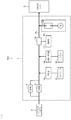
- FIG. 1 illustrates a configuration example of a power supply system 100 according to one embodiment of the present technology.
- the power supply system 100 includes, for example, a power control apparatus 1, a system power 2, and a demand load (hereinafter referred to as a load as appropriate) 3. Power is supplied from the system power 2 to the load 3 through the power control apparatus 1.
- the load 3 is, for example, a factory or a building that produces semiconductors or the like, but is not limited thereto.
- the flow of electric power is indicated by a thick line.
- the power control apparatus 1 is an apparatus for preventing occurrence of an adverse effect on the load 3 due to a momentary drop or a long-time power failure.
- the momentary drop is a phenomenon that voltage from the system power 2 drops momentarily (for example, less than 1 second (about 2 ms (milliseconds) as a more specific example)).
- the power control apparatus 1 includes a high speed switch (HSS) 10 that is an example of a switch unit, a synchronous system (SYS) 11 that is an example of a synchronization control unit, a power conditioning system (PCS) 12 that is an example of a first power control unit, a capacitor 13 that is an example of a first power storage unit, a lithium ion battery (LiB)-PCS 14, an LiB secondary battery 15 that is an example of a second power storage unit, a rotary machine generator 16, an energy management system (EMS) 17, and a power measuring device 18.
- the second power control unit is constituted of the LiB-PCS 14 and the EMS 17.
- the HSS 10 and the power measuring device 18 are connected to a power supply line PL from the system power 2 to the load 3.
- the SYS 11 is connected in parallel to the HSS 10.
- the PCS 12 is connected to the power supply line PL.
- the PCS 12 is connected to the capacitor 13 and is configured so that power output from the capacitor 13 can be supplied to the load 3 according to control by the PCS 12.
- the LiB-PCS 14 is connected to the power supply line PL.
- the LiB-PCS 14 is connected to the LiB secondary battery 15, and is configured so that power output from the LiB secondary battery 15 can be supplied to the load 3 according to control by the LiB-PCS 14.
- a rotary machine generator 16 is connected to the power supply line PL, and is configured so that power output from the rotary machine generator 16 can be supplied to the load 3.
- the HSS 10 is a switch unit that turns on and off power supply between the system power 2 and the load 3.
- the HSS 10 has a monitoring function for monitoring voltage supplied from the system power 2, a communication function for communicating with the PCS 12, and so on, and has a configuration of a microcomputer, a communication unit, and so on for executing these functions.
- the HSS 10 detects that the voltage supplied from the system power 2 has dropped below a predetermined threshold, the HSS 10 quickly interrupts power supply from the system power 2. Further, the HSS 10 outputs a signal indicating that the voltage from the system power 2 has dropped below the predetermined threshold (hereinafter referred to as a voltage drop signal VS as appropriate) to the PCS 12.
- a voltage drop signal VS as appropriate
- the SYS 11 turns on the HSS 10 after synchronizing a voltage cycle of the system power 2 with a voltage cycle of voltage supplied to the load 3 at a time when voltage of the system power 2 has recovered. For example, the SYS 11 performs the synchronization by matching a zero cross of the voltage cycle of the system power 2 with a zero cross of the voltage cycle of the voltage that is supplied to the load 3 at a time when the voltage of the system power 2 has recovered.
- the PCS 12 for example, has a function of controlling output of the capacitor 13, a function of converting DC power of the capacitor 13 into AC power and supplying the AC power to the load 3, a communication function, and the like, and has a configuration of a microcomputer, a converter, a communication unit, and the like for executing these functions.
- the PCS 12 When the PCS 12 has received the voltage drop signal VS from the HSS 10, the PCS 12 performs control to supply power from the capacitor 13 to the load 3, and outputs a discharge start signal DS.
- the capacitor 13 is, for example, an electric double layer capacitor, and is a power storage unit that outputs DC power.
- a lead secondary battery, a combination of these, or the like can be used as a power storage unit that outputs DC power.
- a dischargeable time of the capacitor 13 is, for example, set short as compared to a time necessary for the rotary machine generator 16 to start discharging. As an example, the dischargeable time of the capacitor 13 is 2 to 3 seconds, and the time necessary for the rotary machine generator 16 to start discharging after starting operation is about 1 to 2 minutes.
- the LiB-PCS 14 has, for example, a function of controlling output of the LiB secondary battery 15, a function of converting DC power of the LiB secondary battery 15 into AC power and supplying the AC power to the load 3, and the like, and has a configuration of a microcomputer, a converter, and the like for executing these functions.
- the LiB-PCS 14 can operate, for example, in a first control mode and a second control mode, and executes different control depending on the set control mode.
- the first control mode is a control mode that is set in the LiB-PCS 14 when the LiB-PCS 14 receives the discharge start signal DS.
- the second control mode is a control mode set in the LiB-PCS 14 after the rotary machine generator 16 starts discharging.
- the LiB-PCS 14 in which the first control mode is set controls output of the LiB secondary battery 15 so that all power output from the LiB secondary battery 15 is supplied to the load 3.
- the LiB-PCS 14 in which the second control mode is set controls output of the LiB secondary battery 15 so as to cause the LiB secondary battery 15 to discharge in cooperation with output from the rotary machine generator 16.
- the LiB secondary battery 15 has one or more lithium ion secondary batteries. Further, the LiB secondary battery 15 has a known configuration for monitoring voltage, current, temperature, and the like of the lithium ion secondary battery and a communication unit that communicates with the EMS 17. A detailed configuration example of the LiB secondary battery 15 will be described later.
- the rotary machine generator 16 is a device that generates electric power by rotating a rotor.
- the power source for rotating the rotor is gasoline, gas, or the like and not particularly limited.
- a cogeneration system (CGS) is employed as an example of the rotary machine generator 16.
- the CGS is a system that collects waste heat generated during power generation while supplying the load 3 with power generated by the rotary machine generator 16.
- the recovered waste heat is used as steam or hot water for heat sources, air conditioning, hot water supply, and the like of a factory.
- the rotary machine generator 16 has a communication function and the like in addition to the power generation function, and has a configuration such as a communication unit for executing these functions.
- the rotary machine generator 16 starts operation when having received an operation control signal CS1 described later.
- the EMS 17 has, for example, a function for monitoring power of the power supply line PL based on data supplied from the power measuring device 18, a communication function, and so on, and has a microcomputer, a communication unit, and so on for executing these functions.
- the EMS 17 is configured to be capable of communicating with each of the PCS 12, the LiB-PCS 14, the LiB secondary battery 15, and the rotary machine generator 16.
- the power measuring device 18 is omitted from illustration as appropriate.
- the EMS 17 When the EMS 17 has received the discharge start signal DS from the PCS 12, the EMS 17 supplies the discharge start signal DS to the LiB-PCS 14. Further, the EMS 17 obtains information corresponding to a remaining capacity of the LiB secondary battery 15 from the LiB secondary battery 15. In the present embodiment, state of charge (SoC) is used as information corresponding to the remaining capacity. Information based on depth of discharge (DoD) or other information may be used as information corresponding to the remaining capacity.
- SoC data SD described later
- the EMS 17 When the EMS 17 has received a signal (SoC data SD described later) indicating that the SoC has become smaller than a threshold (hereinafter referred to as a set value as appropriate), the EMS 17 outputs an operation control signal CS1 to the rotary machine generator 16.
- LiB secondary battery 15 may also be referred to as an energy storage system (ESS).
- ESS energy storage system
- the LiB secondary battery 15 has a battery management unit (BMU)-HUB 20 and a string STR connected to the BMU-HUB 20.
- the BMU-HUB 20 has a micro-control unit (MCU) 20a for executing functions of the BMU-HUB 20.
- the BMU-HUB 20 is configured to be capable of communicating with the EMS 17. For example, a maximum of 64 strings STR can be connected in parallel to the BMU-HUB 20, and an appropriate number of strings STR corresponding to necessary output are connected to the BMU-HUB 20.
- the string STR includes one BMU 21 and one or more modules (power storage modules) 22.
- the BMU 21 has an MCU 21a for executing the functions of the BMU 21.
- the BMU 21 is configured to be capable of communicating with the BMU-HUB 20. For example, a maximum of 32 modules 22 can be connected in series to the BMU 21, and an appropriate number of modules 22 corresponding to a necessary output are connected to the BMU 21.
- the module 22 has a battery unit constituted of a lithium ion secondary battery and an MCU 22a for executing functions of the module 22.
- the lithium ion secondary battery in the present embodiment is a lithium ion secondary battery including a positive electrode active material and a carbon material such as graphite as a negative electrode active material, and includes a positive electrode active material having an olivine structure as a positive electrode material.
- the positive electrode active material having an olivine structure is preferably a lithium iron phosphate compound (LiFePO 4 ) or a lithium iron complex phosphate compound containing heteroatoms (LiFe x M 1-x O 4 : M represents one or more types of metal, and x is 0 ⁇ x ⁇ 1). When two or more types of M are included, they are selected so that the sum of subscripts is 1 - x.
- M examples include transition elements, group IIA elements, group IIIA elements, group IIIB elements, group IVB elements, and the like.
- those containing at least one type of cobalt (Co), nickel, manganese (Mn), iron, aluminum, vanadium (V), or titanium (Ti) are preferable.
- the surface of the lithium iron phosphate compound or lithium iron composite phosphate compound may be provided with a coating layer including a metal oxide (one selected from, for example, Ni, Mn, Li, or the like) or phosphate compound (for example, lithium phosphate or the like) having a composition different from that of the above-mentioned lithium iron phosphate compound or lithium iron composite phosphate compound.
- a metal oxide one selected from, for example, Ni, Mn, Li, or the like
- phosphate compound for example, lithium phosphate or the like
- a lithium composite oxide such as lithium cobaltate (LiCoO 2 ), lithium nickelate (LiNiO 2 ), and lithium manganate (LiMnO 2 ) having a laminar rock salt structure, and lithium manganate (LiMn 2 O 4 ) with spinel structure may be used as a positive electrode material capable of storing and releasing lithium (Li).
- the graphite used as the negative electrode active material there is no limitation in particular as the graphite used as the negative electrode active material, and a wide variety of graphite materials used in the industry can be used.
- a negative electrode material lithium titanate, silicon (Si)-based material, tin (Sn)-based material, or the like may be used.
- the method for producing the battery electrode is not particularly limited, and a wide variety of methods used in the industry can be used.
- electrolyte solution used for the present technology is not particularly limited, and a wide variety of electrolyte solutions used in the industry including ones in liquid forms and gel forms can be used.
- 16 battery blocks are connected, each including eight lithium ion secondary batteries (single cells) described above connected in parallel. Connecting 8 batteries in parallel is called 8P (Parallel), and connecting 16 battery blocks in series is called 16S (Series).
- 8P Parallel
- 16S Series
- the battery unit of the module 22 has an 8P16S configuration. When an average output of the lithium ion secondary batteries is 3.2 V (volt), one module 22 outputs 51.2 V (16 ⁇ 3.2 V).
- the MCU 22a of the module 22 monitors voltage, current, and temperature of each battery block, and outputs monitoring results to a higher BMU 21 as battery information. Note that monitoring of voltage and so on may be performed in units of cells or a plurality of battery blocks. The battery information is appropriately converted into digital data and output. AD (Analog to Digital) conversion processing and so on are performed by the MCU 22a.
- the BMU 21 manages charging and discharging of each module 22 by appropriately turning on and off charging and discharging control switches (the switch SW1 and the switch SW2 in FIG. 7 described later) based on battery information transmitted from each module 22.
- the switches SW1 and SW2 are normally on (conductive state) and are turned off when an abnormality occurs.
- the BMU 21 performs a balancing process so that the degree of deterioration does not vary among the modules 22.
- the BMU 21 transmits the battery information transmitted from each module 22 to the BMU-HUB 20.
- the BMU-HUB 20 outputs SoC data SD to the EMS 17 when, for example, the SoC of the module 22 becomes smaller than 50% (half capacity).
- the BMU-HUB 20 When a plurality of modules 22 are applied, the BMU-HUB 20 outputs the SoC data SD to the EMS 17 when the smallest SoC among the modules 22 becomes smaller than 50%.
- the BMU-HUB 20 may output the SoC data SD to the EMS 17 as needed.
- the EMU 17 may be referred to as an integrated controller or the like, and the BMU may each be referred to as a control box or the like.
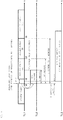
- Axes in FIGS. 3 to 5 indicate time axes.
- a time axis TL1 is a time axis corresponding to a time when a phenomenon that the voltage of the system power 2 falls below a threshold and a time when the voltage recovers and the system power 2 is restored.
- 3 to 5 for example, a pattern in which the voltage of the system power 2 decreases at time t0 and the system power 2 is restored at time t1 that is one second after time t0 (system power (a)) (momentary drop), a pattern in which the system power 2 is restored at time t2 that is 10 seconds after time t0 (system power (b)), a pattern in which the system power 2 is restored at time t3 that is 3 to 10 minutes after time t0 (system power (c)), and a pattern in which the system power 2 is restored at time t4 that is 15 minutes after the time t0 (system power (d)) are illustrated.
- a time axis TL2 indicates a period during which the capacitor 13 discharges
- a time axis TL3 indicates a period during which the LiB secondary battery 15 discharges
- a time axis TL4 indicates a period during which the rotary machine generator 16 discharges.
- the capacitor 13 starts discharging according to control by the PCS 12. Electric power is output from the capacitor 13 in a short time (for example, 1 ms to 2 ms or less) from time t0.
- the capacitor 13 is generally configured to have a dischargeable period of about 3 seconds in consideration of cost and the like.
- the power supply to the load 3 can be continued by the power output from the capacitor 13.
- the dischargeable time of the lead secondary battery is generally about 2 to 3 minutes. This is because, in order to secure a longer dischargeable time, a large number of lead secondary batteries are necessary, which is disadvantageous in terms of cost, space for arranging the lead secondary batteries, an increase in weight, and the like. Even when the lead secondary battery is used, the same problem can occur when the time during which the voltage drop of the system power 2 continues is longer than several minutes.
- the LiB secondary battery 15 starts discharging according to control by the LiB-PCS 14 (for example, within 1 second).
- the LiB secondary battery 15 is configured to have a dischargeable time of, for example, 10 minutes to 15 minutes, and thus it is possible to continue the power to the load 3 even when a power failure occurs for a relatively long time from time t0, and the capacitor 13 has no remaining capacity and the capacitor 13 stops discharging. Since the LiB secondary battery 15 is capable of outputting high power, even when the LiB secondary battery 15 is configured to have a dischargeable time of, for example, 10 minutes to 15 minutes, it is possible to prevent the arrangement space thereof from greatly increasing.
- the power supply from the system power 2 is stopped for a longer time (for example, 15 minutes or more).
- a longer time for example, 15 minutes or more.
- the rotary machine generator 16 when the SoC of the LiB secondary battery 15 becomes smaller than a set value (for example, 50%), the rotary machine generator 16 starts to operate. A certain time (for example, about 1 to 2 minutes) is needed until the rotary machine generator 16 starts operating and actually starts discharging. Accordingly, the set value for the SoC is appropriately set so that the rotary machine generator 16 starts to operate when the remaining capacity of the LiB secondary battery 15 is relatively large.
- a set value for example, 50%
- the set value for the SoC may be changed according to the state of the load, that is, the necessary power amount. For example, when the load is larger than a predetermined value, operation of the rotary machine generator 16 is started when the SoC becomes smaller than 50%, and when the load is smaller than the predetermined value, operation of the rotary machine generator 16 is started when the SoC becomes smaller than 30%. In this way, start of operation of the rotary machine generator 16 can be delayed by changing the set value of the SoC for starting operation of the rotary machine generator 16 according to the size of the load.
- All of the power output from the LiB secondary battery 15 is supplied to the load 3 until the rotary machine generator 16 starts discharging.
- the LiB-PCS 14 operates in the second control mode, and thus output of the LiB secondary battery 15 helps (assists) output of the rotary machine generator 16.
- a voltage fluctuation or a frequency fluctuation may occur in output of the rotary machine generator 16 when a sudden power load fluctuation occurs.
- switching to output control linked to output voltage and frequency of the rotary machine generator 16 is performed without stopping the discharge from the LiB secondary battery 15 even after the rotary machine generator 16 starts discharging.
- a voltage drop or frequency fluctuation that may occur when a sudden load fluctuation occurs is compensated by output from the LiB secondary battery 15. In this manner, stable power supply to the load 3 becomes possible.
- Patent Document 1 in a configuration in which a configuration related to power generation is controlled by a single control unit, the control unit and the like need to be changed along with a change in the configuration related to power generation, and existing equipment that is generally used cannot be used.
- the control unit and the like need to be changed along with a change in the configuration related to power generation, and existing equipment that is generally used cannot be used.
- the existing equipment can be used, and at the same time, costs of additional investment can be reduced.
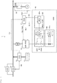
- FIG. 6 is a flowchart illustrating an operation flow of the power control apparatus 1.
- FIG. 7 is a diagram mainly illustrating a signal flow (dotted arrow) in the power control apparatus 1.
- step ST1 the HSS 10 determines whether or not the voltage of power supplied from the system power 2 has become smaller than a threshold.
- the process returns to step ST1, and the determination process of step ST1 is repeated.
- the process proceeds to step ST2.
- step ST2 the HSS 10 interrupts the system and interrupts the power supply from the system power 2, and outputs the voltage drop signal VS to the PCS 12. Then, the process proceeds to step ST3.
- step ST3 the PCS 12 that has received the voltage drop signal VS performs control to convert DC power supplied from the capacitor 13 into AC power and supply the AC power to the load 3.
- the capacitor 13 stops discharging after a predetermined period until the capacitance runs out (for example, after several seconds). Further, the PCS 12 outputs a discharge start signal DS. Then, the process proceeds to step ST4.
- step ST4 the discharge start signal DS output from the PCS 12 is received by the EMS 17.
- the EMS 17 supplies the discharge start signal DS to the LiB-PCS 14 using a predetermined communication line SL1 between the EMS 17 and the LiB-PCS 14.
- the discharge start signal DS output from the PCS 12 is supplied to the LiB-PCS 14 through the EMS 17.
- the LiB-PCS 14 that has received the discharge start signal DS performs control to cause the LiB secondary battery 15 to discharge, converts DC power output from the LiB secondary battery 15 into AC power, and supplies the AC power to the load 3.
- the LiB-PCS 14 operates in the first control mode, and supplies all of the power output from the LiB secondary battery 15 to the load 3. Then, the process proceeds to step ST5.
- step ST5 it is determined whether or not the SoC of the LiB secondary battery 15 has become smaller than a set value (for example, 50%).
- the SoC of the module 22 constituting the LiB secondary battery 15 is monitored by the MCU 22a, and a monitoring result is supplied to the MCU 20a of the BMU-HUB 20 through the MCU 21a of the higher BMU 21.
- the MCU 20a determines whether or not the SoC of the module 22 has become smaller than 50%.
- a plurality of modules 22 are used, for example, it is determined whether or not the smallest SoC is smaller than 50%.
- step ST5 If the SoC of the LiB secondary battery 15 is larger than 50%, the process returns to step ST5, and the determination process of step ST5 is repeated.
- the MCU 20a supplies SoC data SD indicating that the SoC is smaller to the EMS 17 using a predetermined communication line SL2 between the EMS 17 and the LiB secondary battery 15. Then, the process proceeds to step ST6.
- step ST6 the EMS 17 that has received the SoC data SD outputs an operation control signal CS1.
- the operation control signal CS1 output from the EMS 17 is received by the rotary machine generator 16. Then, the process proceeds to step ST7.
- the rotary machine generator 16 that has received the operation control signal CS1 starts operation.
- a predetermined time (for example, about 1 to 2 minutes) is necessary until the rotary machine generator 16 having started operation starts discharging.
- the EMS 17 determines whether or not the rotary machine generator 16 has started discharging.
- a time until the rotary machine generator 16 starts discharging after outputting the operation control signal CS1 is stored in advance in the EMS 17, and when the time has elapsed after outputting the operation control signal CS1, the EMS 17 can recognize that the rotary machine generator 16 has started discharging.
- the rotary machine generator 16 may supply the EMS 17 with a discharge start signal indicating that the rotary machine generator 16 has started discharging so that the EMS 17 recognizes that the rotary machine generator 16 has started discharging.
- step ST7 when the rotary machine generator 16 has not started discharging, the process returns to step ST7, and the determination process of step ST7 is repeated.
- the process proceeds to step ST8.
- step ST8 the EMS 17 having recognized that the rotary machine generator 16 has started discharging supplies an operation control signal CS2 to the LiB-PCS 14.
- the LiB-PCS 14 that has received the operation control signal CS2 switches the control mode from the first control mode to the second control mode, and controls output from the LiB secondary battery 15 in the second control mode.
- output from the LiB secondary battery 15 is controlled so that, for example, a voltage drop and a frequency fluctuation that may occur when a sudden load change occurs are compensated by output of the LiB secondary battery 15.
- the power supply to the load 3 can be continued when a momentary drop occurs and also when power supply from the system power 2 is stopped for a long time.
- a signal indicating the restoration of the power is supplied from the HSS 10 to the PCS 12, the LiB-PCS 14, and the rotary machine generator 16, so as to perform control to stop discharge from the capacitor 13, the LiB secondary battery 15, and the rotary machine generator 16.
- the HSS 10 When the HSS 10 is turned on, power of the system power 2 is supplied to the load 3.
- the SYS 11 performs synchronization control to turn on the HSS 10 after synchronizing the voltage cycle of the system power 2 with the voltage cycle of the voltage supplied to the load 3.
- the capacitor 13 and the LiB secondary battery 15 are charged by power from the system power 2 through the PCS 12 and the LiB-PCS 14, respectively.
- a communication line SL3 may be set between the LiB-PCS 14 and the LiB secondary battery 15 so that the LiB-PCS 14 and the MCU 20a of the BMU-HUB 20 communicate with each other.
- a communication line SL4 may be set between the LiB secondary battery 15 and the rotary machine generator 16.
- the MCU 20a of the BMU-HUB 20 may be configured to output the operation control signal CS1 when the SoC of the module 22 becomes smaller than a set value, and the operation control signal CS1 may be supplied to the rotary machine generator 16 without passing through the EMS 17.
- respective components may communicate without intervention of the EMS 17.
- other configurations may have the functions of the EMS 17 in a sharing manner.
- the communication may be wired communication, wireless communication, or communication using both wired and wireless communication.
- the EMS 17 may perform the process of determining whether or not the SoC of the module 22 has become smaller than 50% (the process of step ST5).
- the MCU 20a of the BMU-HUB 20 periodically transmits the SoCs of all the modules 22 to the EMS 17.
- the EMS 17 determines whether or not there is a module 22 having an SoC smaller than 50%. Then, when there is a module 22 having an SoC smaller than 50%, the EMS 17 may supply the operation control signal CS1 to the rotary machine generator 16 similarly to one embodiment described above.
- control may be performed to stop the output from the LiB secondary battery 15 after the rotary machine generator 16 has discharged.
- the power control apparatus 1 may have no BMU-HUB 20.
- the capacitor 13 and the LiB secondary battery 15 may be charged with power supplied from the system power 2.
- the configurations, methods, steps, shapes, materials, numerical values, and the like given in the embodiments described above are merely examples, and different configurations, methods, steps, shapes, materials, numerical values, and the like may be used as necessary.
- the present technology can be realized in any form such as a method, a system, a program, and a storage medium storing the program.
Landscapes
- Engineering & Computer Science (AREA)
- Power Engineering (AREA)
- Business, Economics & Management (AREA)
- Emergency Management (AREA)
- Charge And Discharge Circuits For Batteries Or The Like (AREA)
- Supply And Distribution Of Alternating Current (AREA)
- Stand-By Power Supply Arrangements (AREA)
Abstract
Description
- The present technology relates to a power control apparatus and a power control method.
- There is known a phenomenon called so-called momentary voltage drop (hereinafter referred to as momentary drop as appropriate) in which voltage from a system power (commercial power supply) drops momentarily. Although the momentary drop is mostly caused by natural phenomena such as lightening, wind and rain, and ice and snow, it can also be caused by birds and animals or human error. When a momentary drop occurs, a production line of a production plant may stop, and there is a risk that product manufacturing defects or equipment damage may occur. In addition, what is called power failure may occur where the voltage continues to decrease. For this reason, it is desired to construct a power supply system corresponding to an abnormality of the system power.
Patent Document 1 listed below describes a system that autonomously operates a distributed power supply when an abnormality occurs in the system power. - Patent Document 1: Japanese Patent Application Laid-Open No.
2009-219204 - In such a field, it is desired to construct a system that can reliably supply power to a load when an abnormality occurs in power supply from a system power.
- Therefore, it is an object of the present technology to provide a power control apparatus and a power control method that can reliably supply power to a load when an abnormality occurs in power supply from the system power.
- The present technology is, for example, a power control apparatus having:
- a switch unit that interrupts power supply from a system power when the switch unit detects a drop of voltage from the system power below a threshold;
- a first power control unit that receives a voltage drop signal supplied from the switch unit;
- a first power storage unit connected to the first power control unit;
- a second power control unit that receives a discharge start signal supplied from the first power control unit;
- a second power storage unit connected to the second power control unit; and
- a rotary machine generator that receives an operation control signal supplied from the second power control unit or the second power storage unit.
- The present technology is, for example, a power control method including:
- by a switch unit, interrupting power supply from a system power and outputting a voltage drop signal when the switch unit detects a drop of voltage from the system power below a threshold;
- by a first power control unit, performing control to supply power to a load from a first power storage unit and outputting a discharge start signal when the first power control unit receives the voltage drop signal;
- by a second power control unit, performing control to supply power to the load from a second power storage unit when the second power control unit receives the discharge start signal; and
- by a rotary machine generator, starting operation to supply power to the load when the rotary machine generator receives an operation control signal from the second power control unit or the second power storage unit.
- According to at least an embodiment of the present technology, when an abnormality occurs in power supply from a system power, power can be reliably supplied to a load. Note that the effect described here is not necessarily limited and may be any effect described in the present technology. Further, the contents of the present technology are not interpreted as being limited by the exemplified effects.
-
-
FIG. 1 is a block diagram illustrating a configuration example of a power supply system according to one embodiment of the present technology. -
FIG. 2 is a block diagram illustrating a configuration example of an LiB secondary battery according to one embodiment of the present technology. -
FIG. 3 is a diagram for describing an operation example and the like of a power control apparatus according to one embodiment of the present technology. -
FIG. 4 is a diagram for explaining an operation example and the like of the power control apparatus according to one embodiment of the present technology. -
FIG. 5 is a diagram for explaining an operation example and the like of the power control apparatus according to one embodiment of the present technology. -
FIG. 6 is a flowchart illustrating a process flow of the power control apparatus according to one embodiment of the present technology. -
FIG. 7 is a diagram for explaining a signal flow in the power control apparatus according to one embodiment of the present technology. -
FIG. 8 is a diagram for explaining a modification example. -
FIG. 9 is a diagram for explaining a modification example. - Hereinafter, embodiments of the present technology and the like will be described with reference to the drawings. The description will be made in the following order.
- Embodiments and the like described below are preferable specific examples of the present technology, and the contents of the present technology are not limited to these embodiments and the like.
-
FIG. 1 illustrates a configuration example of apower supply system 100 according to one embodiment of the present technology. Thepower supply system 100 includes, for example, apower control apparatus 1, asystem power 2, and a demand load (hereinafter referred to as a load as appropriate) 3. Power is supplied from thesystem power 2 to theload 3 through thepower control apparatus 1. Theload 3 is, for example, a factory or a building that produces semiconductors or the like, but is not limited thereto. InFIG. 1 , the flow of electric power is indicated by a thick line. - The
power control apparatus 1 according to one embodiment is an apparatus for preventing occurrence of an adverse effect on theload 3 due to a momentary drop or a long-time power failure. The momentary drop is a phenomenon that voltage from thesystem power 2 drops momentarily (for example, less than 1 second (about 2 ms (milliseconds) as a more specific example)). - A configuration example of the
power control apparatus 1 will be described. Thepower control apparatus 1 includes a high speed switch (HSS) 10 that is an example of a switch unit, a synchronous system (SYS) 11 that is an example of a synchronization control unit, a power conditioning system (PCS) 12 that is an example of a first power control unit, acapacitor 13 that is an example of a first power storage unit, a lithium ion battery (LiB)-PCS 14, an LiBsecondary battery 15 that is an example of a second power storage unit, arotary machine generator 16, an energy management system (EMS) 17, and apower measuring device 18. In the present embodiment, the second power control unit is constituted of the LiB-PCS 14 and the EMS 17. - The HSS 10 and the
power measuring device 18 are connected to a power supply line PL from thesystem power 2 to theload 3. The SYS 11 is connected in parallel to the HSS 10. The PCS 12 is connected to the power supply line PL. The PCS 12 is connected to thecapacitor 13 and is configured so that power output from thecapacitor 13 can be supplied to theload 3 according to control by thePCS 12. The LiB-PCS 14 is connected to the power supply line PL. The LiB-PCS 14 is connected to the LiBsecondary battery 15, and is configured so that power output from the LiBsecondary battery 15 can be supplied to theload 3 according to control by the LiB-PCS 14. Arotary machine generator 16 is connected to the power supply line PL, and is configured so that power output from therotary machine generator 16 can be supplied to theload 3. - The
HSS 10 is a switch unit that turns on and off power supply between thesystem power 2 and theload 3. TheHSS 10 has a monitoring function for monitoring voltage supplied from thesystem power 2, a communication function for communicating with thePCS 12, and so on, and has a configuration of a microcomputer, a communication unit, and so on for executing these functions. When theHSS 10 detects that the voltage supplied from thesystem power 2 has dropped below a predetermined threshold, theHSS 10 quickly interrupts power supply from thesystem power 2. Further, theHSS 10 outputs a signal indicating that the voltage from thesystem power 2 has dropped below the predetermined threshold (hereinafter referred to as a voltage drop signal VS as appropriate) to thePCS 12. - When voltage supplied from the
system power 2 drops below the threshold and then this voltage recovers, theSYS 11 turns on theHSS 10 after synchronizing a voltage cycle of thesystem power 2 with a voltage cycle of voltage supplied to theload 3 at a time when voltage of thesystem power 2 has recovered. For example, theSYS 11 performs the synchronization by matching a zero cross of the voltage cycle of thesystem power 2 with a zero cross of the voltage cycle of the voltage that is supplied to theload 3 at a time when the voltage of thesystem power 2 has recovered. In addition, at a time when the voltage of thesystem power 2 has recovered, cases are conceivable where power of only the LiBsecondary battery 15 is supplied to theload 3, power is supplied from the LiBsecondary battery 15 and therotary machine generator 16 to theload 3, and only power of therotary machine generator 16 is supplied to theload 3. - The
PCS 12, for example, has a function of controlling output of thecapacitor 13, a function of converting DC power of thecapacitor 13 into AC power and supplying the AC power to theload 3, a communication function, and the like, and has a configuration of a microcomputer, a converter, a communication unit, and the like for executing these functions. When thePCS 12 has received the voltage drop signal VS from theHSS 10, thePCS 12 performs control to supply power from thecapacitor 13 to theload 3, and outputs a discharge start signal DS. - The
capacitor 13 is, for example, an electric double layer capacitor, and is a power storage unit that outputs DC power. In addition, besides the capacitor, a lead secondary battery, a combination of these, or the like can be used as a power storage unit that outputs DC power. A dischargeable time of thecapacitor 13 is, for example, set short as compared to a time necessary for therotary machine generator 16 to start discharging. As an example, the dischargeable time of thecapacitor 13 is 2 to 3 seconds, and the time necessary for therotary machine generator 16 to start discharging after starting operation is about 1 to 2 minutes. - The LiB-
PCS 14 has, for example, a function of controlling output of the LiBsecondary battery 15, a function of converting DC power of the LiBsecondary battery 15 into AC power and supplying the AC power to theload 3, and the like, and has a configuration of a microcomputer, a converter, and the like for executing these functions. The LiB-PCS 14 can operate, for example, in a first control mode and a second control mode, and executes different control depending on the set control mode. The first control mode is a control mode that is set in the LiB-PCS 14 when the LiB-PCS 14 receives the discharge start signal DS. The second control mode is a control mode set in the LiB-PCS 14 after therotary machine generator 16 starts discharging. The LiB-PCS 14 in which the first control mode is set controls output of the LiBsecondary battery 15 so that all power output from the LiBsecondary battery 15 is supplied to theload 3. The LiB-PCS 14 in which the second control mode is set controls output of the LiBsecondary battery 15 so as to cause the LiBsecondary battery 15 to discharge in cooperation with output from therotary machine generator 16. - The LiB
secondary battery 15 has one or more lithium ion secondary batteries. Further, the LiBsecondary battery 15 has a known configuration for monitoring voltage, current, temperature, and the like of the lithium ion secondary battery and a communication unit that communicates with theEMS 17. A detailed configuration example of the LiBsecondary battery 15 will be described later. - The
rotary machine generator 16 is a device that generates electric power by rotating a rotor. The power source for rotating the rotor is gasoline, gas, or the like and not particularly limited. In the present embodiment, a cogeneration system (CGS) is employed as an example of therotary machine generator 16. The CGS is a system that collects waste heat generated during power generation while supplying theload 3 with power generated by therotary machine generator 16. The recovered waste heat is used as steam or hot water for heat sources, air conditioning, hot water supply, and the like of a factory. Therotary machine generator 16 has a communication function and the like in addition to the power generation function, and has a configuration such as a communication unit for executing these functions. Therotary machine generator 16 starts operation when having received an operation control signal CS1 described later. - The
EMS 17 has, for example, a function for monitoring power of the power supply line PL based on data supplied from thepower measuring device 18, a communication function, and so on, and has a microcomputer, a communication unit, and so on for executing these functions. In the present embodiment, theEMS 17 is configured to be capable of communicating with each of thePCS 12, the LiB-PCS 14, the LiBsecondary battery 15, and therotary machine generator 16. In other drawings, thepower measuring device 18 is omitted from illustration as appropriate. - When the
EMS 17 has received the discharge start signal DS from thePCS 12, theEMS 17 supplies the discharge start signal DS to the LiB-PCS 14. Further, theEMS 17 obtains information corresponding to a remaining capacity of the LiBsecondary battery 15 from the LiBsecondary battery 15. In the present embodiment, state of charge (SoC) is used as information corresponding to the remaining capacity. Information based on depth of discharge (DoD) or other information may be used as information corresponding to the remaining capacity. When theEMS 17 has received a signal (SoC data SD described later) indicating that the SoC has become smaller than a threshold (hereinafter referred to as a set value as appropriate), theEMS 17 outputs an operation control signal CS1 to therotary machine generator 16. - Specific numerical examples corresponding to the respective configurations will be described. Note that these numerical values are examples for facilitating understanding of one embodiment of the present technology, and the contents of the present technology are not limited to the numerical values exemplified below.
- Power demand of load 3: 6000 kW
- The
PCS 12 and LiB-PCS 14: 6000 kVA - The capacitor 13: 5 kWh
- The LiB secondary battery 15: 1700 kW (DC (Direct Current) voltage: 624 to 750 V)
- Next, a detailed configuration example of the LiB
secondary battery 15 will be described with reference toFIG. 2 . InFIG. 2 , respective configurations of the LiBsecondary battery 15 and theEMS 17 are illustrated. Note that the LiBsecondary battery 15 may also be referred to as an energy storage system (ESS). - The LiB
secondary battery 15 has a battery management unit (BMU)-HUB 20 and a string STR connected to the BMU-HUB 20. The BMU-HUB 20 has a micro-control unit (MCU) 20a for executing functions of the BMU-HUB 20. The BMU-HUB 20 is configured to be capable of communicating with theEMS 17. For example, a maximum of 64 strings STR can be connected in parallel to the BMU-HUB 20, and an appropriate number of strings STR corresponding to necessary output are connected to the BMU-HUB 20. - The string STR includes one
BMU 21 and one or more modules (power storage modules) 22. TheBMU 21 has anMCU 21a for executing the functions of theBMU 21. TheBMU 21 is configured to be capable of communicating with the BMU-HUB 20. For example, a maximum of 32modules 22 can be connected in series to theBMU 21, and an appropriate number ofmodules 22 corresponding to a necessary output are connected to theBMU 21. - The
module 22 has a battery unit constituted of a lithium ion secondary battery and anMCU 22a for executing functions of themodule 22. - The lithium ion secondary battery in the present embodiment is a lithium ion secondary battery including a positive electrode active material and a carbon material such as graphite as a negative electrode active material, and includes a positive electrode active material having an olivine structure as a positive electrode material.
- More preferably, the positive electrode active material having an olivine structure is preferably a lithium iron phosphate compound (LiFePO4) or a lithium iron complex phosphate compound containing heteroatoms (LiFexM1-xO4: M represents one or more types of metal, and x is 0 < x < 1). When two or more types of M are included, they are selected so that the sum of subscripts is 1 - x.
- Examples of M include transition elements, group IIA elements, group IIIA elements, group IIIB elements, group IVB elements, and the like. In particular, those containing at least one type of cobalt (Co), nickel, manganese (Mn), iron, aluminum, vanadium (V), or titanium (Ti) are preferable.
- As to the positive electrode active material, the surface of the lithium iron phosphate compound or lithium iron composite phosphate compound may be provided with a coating layer including a metal oxide (one selected from, for example, Ni, Mn, Li, or the like) or phosphate compound (for example, lithium phosphate or the like) having a composition different from that of the above-mentioned lithium iron phosphate compound or lithium iron composite phosphate compound.
- A lithium composite oxide such as lithium cobaltate (LiCoO2), lithium nickelate (LiNiO2), and lithium manganate (LiMnO2) having a laminar rock salt structure, and lithium manganate (LiMn2O4) with spinel structure may be used as a positive electrode material capable of storing and releasing lithium (Li).
- There is no limitation in particular as the graphite used as the negative electrode active material, and a wide variety of graphite materials used in the industry can be used. As a negative electrode material, lithium titanate, silicon (Si)-based material, tin (Sn)-based material, or the like may be used.
- The method for producing the battery electrode is not particularly limited, and a wide variety of methods used in the industry can be used.
- As an electrolyte solution used for the present technology is not particularly limited, and a wide variety of electrolyte solutions used in the industry including ones in liquid forms and gel forms can be used.
- For example, 16 battery blocks are connected, each including eight lithium ion secondary batteries (single cells) described above connected in parallel. Connecting 8 batteries in parallel is called 8P (Parallel), and connecting 16 battery blocks in series is called 16S (Series). Thus, the battery unit of the
module 22 has an 8P16S configuration. When an average output of the lithium ion secondary batteries is 3.2 V (volt), onemodule 22 outputs 51.2 V (16 × 3.2 V). - The
MCU 22a of themodule 22 monitors voltage, current, and temperature of each battery block, and outputs monitoring results to ahigher BMU 21 as battery information. Note that monitoring of voltage and so on may be performed in units of cells or a plurality of battery blocks. The battery information is appropriately converted into digital data and output. AD (Analog to Digital) conversion processing and so on are performed by theMCU 22a. - The
BMU 21 manages charging and discharging of eachmodule 22 by appropriately turning on and off charging and discharging control switches (the switch SW1 and the switch SW2 inFIG. 7 described later) based on battery information transmitted from eachmodule 22. The switches SW1 and SW2 are normally on (conductive state) and are turned off when an abnormality occurs. In addition, when a plurality ofmodules 22 are applied, theBMU 21 performs a balancing process so that the degree of deterioration does not vary among themodules 22. TheBMU 21 transmits the battery information transmitted from eachmodule 22 to the BMU-HUB 20. The BMU-HUB 20 outputs SoC data SD to theEMS 17 when, for example, the SoC of themodule 22 becomes smaller than 50% (half capacity). When a plurality ofmodules 22 are applied, the BMU-HUB 20 outputs the SoC data SD to theEMS 17 when the smallest SoC among themodules 22 becomes smaller than 50%. The BMU-HUB 20 may output the SoC data SD to theEMS 17 as needed. - The
EMU 17 may be referred to as an integrated controller or the like, and the BMU may each be referred to as a control box or the like. - Next, with reference to
FIGS. 3 to 5 , operation of thepower control apparatus 1 will be schematically described while referring to problems to be considered in thepower control apparatus 1. Axes inFIGS. 3 to 5 (arrows from a left side to a right side in charts) indicate time axes. A time axis TL1 is a time axis corresponding to a time when a phenomenon that the voltage of thesystem power 2 falls below a threshold and a time when the voltage recovers and thesystem power 2 is restored. InFIGS. 3 to 5 , for example, a pattern in which the voltage of thesystem power 2 decreases at time t0 and thesystem power 2 is restored at time t1 that is one second after time t0 (system power (a)) (momentary drop), a pattern in which thesystem power 2 is restored at time t2 that is 10 seconds after time t0 (system power (b)), a pattern in which thesystem power 2 is restored at time t3 that is 3 to 10 minutes after time t0 (system power (c)), and a pattern in which thesystem power 2 is restored at time t4 that is 15 minutes after the time t0 (system power (d)) are illustrated. - Further, a time axis TL2 indicates a period during which the
capacitor 13 discharges, a time axis TL3 indicates a period during which the LiBsecondary battery 15 discharges, and a time axis TL4 indicates a period during which therotary machine generator 16 discharges. - As illustrated in
FIG. 3 , when the voltage of thesystem power 2 falls below the threshold at time t0, power supply from thesystem power 2 is interrupted, and thecapacitor 13 starts discharging according to control by thePCS 12. Electric power is output from thecapacitor 13 in a short time (for example, 1 ms to 2 ms or less) from time t0. Thecapacitor 13 is generally configured to have a dischargeable period of about 3 seconds in consideration of cost and the like. As illustrated inFIG. 3 , when the voltage drop is a momentary drop and the power is restored at time t1, the power supply to theload 3 can be continued by the power output from thecapacitor 13. However, if the time during which the voltage drop of thesystem power 2 continues exceeds the dischargeable period of thecapacitor 13, such as when the power is restored at time t2, the power supply to theload 3 is interrupted. Although an apparatus using a lead secondary battery can be considered instead of thecapacitor 13, the dischargeable time of the lead secondary battery is generally about 2 to 3 minutes. This is because, in order to secure a longer dischargeable time, a large number of lead secondary batteries are necessary, which is disadvantageous in terms of cost, space for arranging the lead secondary batteries, an increase in weight, and the like. Even when the lead secondary battery is used, the same problem can occur when the time during which the voltage drop of thesystem power 2 continues is longer than several minutes. - Accordingly, in the present embodiment, as illustrated in
FIG. 4 , immediately after thecapacitor 13 starts discharging, the LiBsecondary battery 15 starts discharging according to control by the LiB-PCS 14 (for example, within 1 second). The LiBsecondary battery 15 is configured to have a dischargeable time of, for example, 10 minutes to 15 minutes, and thus it is possible to continue the power to theload 3 even when a power failure occurs for a relatively long time from time t0, and thecapacitor 13 has no remaining capacity and thecapacitor 13 stops discharging. Since the LiBsecondary battery 15 is capable of outputting high power, even when the LiBsecondary battery 15 is configured to have a dischargeable time of, for example, 10 minutes to 15 minutes, it is possible to prevent the arrangement space thereof from greatly increasing. - It is also conceivable that the power supply from the
system power 2 is stopped for a longer time (for example, 15 minutes or more). As described above, although the dischargeable time of the LiBsecondary battery 15 is longer than that of thecapacitor 13, when the power supply from thesystem power 2 is stopped for a long time, the remaining capacity of the LiBsecondary battery 15 continues to decrease. Eventually, the discharge from the LiBsecondary battery 15 stops and the power supply to theload 3 becomes impossible. - Accordingly, in the present embodiment, as illustrated in
FIG. 5 , when the SoC of the LiBsecondary battery 15 becomes smaller than a set value (for example, 50%), therotary machine generator 16 starts to operate. A certain time (for example, about 1 to 2 minutes) is needed until therotary machine generator 16 starts operating and actually starts discharging. Accordingly, the set value for the SoC is appropriately set so that therotary machine generator 16 starts to operate when the remaining capacity of the LiBsecondary battery 15 is relatively large. - The set value for the SoC may be changed according to the state of the load, that is, the necessary power amount. For example, when the load is larger than a predetermined value, operation of the
rotary machine generator 16 is started when the SoC becomes smaller than 50%, and when the load is smaller than the predetermined value, operation of therotary machine generator 16 is started when the SoC becomes smaller than 30%. In this way, start of operation of therotary machine generator 16 can be delayed by changing the set value of the SoC for starting operation of therotary machine generator 16 according to the size of the load. - All of the power output from the LiB
secondary battery 15 is supplied to theload 3 until therotary machine generator 16 starts discharging. On the other hand, after therotary machine generator 16 starts discharging, the LiB-PCS 14 operates in the second control mode, and thus output of the LiBsecondary battery 15 helps (assists) output of therotary machine generator 16. A voltage fluctuation or a frequency fluctuation may occur in output of therotary machine generator 16 when a sudden power load fluctuation occurs. Thus, switching to output control linked to output voltage and frequency of therotary machine generator 16 is performed without stopping the discharge from the LiBsecondary battery 15 even after therotary machine generator 16 starts discharging.
Specifically, a voltage drop or frequency fluctuation that may occur when a sudden load fluctuation occurs is compensated by output from the LiBsecondary battery 15. In this manner, stable power supply to theload 3 becomes possible. - Incidentally, a system is also conceivable that responds to a power outage for a long time by increasing the capacitance of the
capacitor 13 to allow discharge for several minutes, and continuing the power supply to theload 3 by always starting operation of therotary machine generator 16 after thecapacitor 13 starts discharging. However, once therotary machine generator 16 is operated, it is necessary to perform maintenance every time, and operation costs increase. For this reason, it is desirable not to start therotary machine generator 16 as much as possible. In the present embodiment, it is possible to lengthen the power supply to theload 3 compared to the configuration with thecapacitor 13 alone by discharging the LiBsecondary battery 15, and thus start of operation of therotary machine generator 16 can be delayed. Therefore, it is possible to prevent therotary machine generator 16 from being started frequently, and it is possible to reduce costs (operation costs) related to maintenance of the entirepower control apparatus 1 and to prevent deterioration of the equipment. - Further, as described in
Patent Document 1, in a configuration in which a configuration related to power generation is controlled by a single control unit, the control unit and the like need to be changed along with a change in the configuration related to power generation, and existing equipment that is generally used cannot be used. However, in the present embodiment, it is only necessary to add the LiBsecondary battery 15 and the configuration for performing output control thereof to the commonly used configuration of theHSS 10, thecapacitor 13, and so on. The existing equipment can be used, and at the same time, costs of additional investment can be reduced. - Next, an operation example of the
power control apparatus 1 will be described with reference toFIGS. 6 and7 .FIG. 6 is a flowchart illustrating an operation flow of thepower control apparatus 1.FIG. 7 is a diagram mainly illustrating a signal flow (dotted arrow) in thepower control apparatus 1. - In step ST1, the
HSS 10 determines whether or not the voltage of power supplied from thesystem power 2 has become smaller than a threshold. TheHSS 10, for example, periodically monitors the voltage of power supplied from thesystem power 2. Being smaller than the threshold may either be equal to or less than the threshold or less than the threshold. Being larger than the threshold may mean being equal to or larger than the threshold, or being larger than the threshold (the same applies to similar expressions in other parts). Here, when the voltage of power supplied from thesystem power 2 is larger than the threshold, the process returns to step ST1, and the determination process of step ST1 is repeated. When the voltage of power supplied from thesystem power 2 becomes smaller than the threshold, the process proceeds to step ST2. - In step ST2, the
HSS 10 interrupts the system and interrupts the power supply from thesystem power 2, and outputs the voltage drop signal VS to thePCS 12. Then, the process proceeds to step ST3. - In step ST3, the
PCS 12 that has received the voltage drop signal VS performs control to convert DC power supplied from thecapacitor 13 into AC power and supply the AC power to theload 3. Thecapacitor 13 stops discharging after a predetermined period until the capacitance runs out (for example, after several seconds). Further, thePCS 12 outputs a discharge start signal DS. Then, the process proceeds to step ST4. - In step ST4, the discharge start signal DS output from the
PCS 12 is received by theEMS 17. TheEMS 17 supplies the discharge start signal DS to the LiB-PCS 14 using a predetermined communication line SL1 between theEMS 17 and the LiB-PCS 14. Thus, in the present embodiment, the discharge start signal DS output from thePCS 12 is supplied to the LiB-PCS 14 through theEMS 17. The LiB-PCS 14 that has received the discharge start signal DS performs control to cause the LiBsecondary battery 15 to discharge, converts DC power output from the LiBsecondary battery 15 into AC power, and supplies the AC power to theload 3. Note that in step ST4, the LiB-PCS 14 operates in the first control mode, and supplies all of the power output from the LiBsecondary battery 15 to theload 3. Then, the process proceeds to step ST5. - In step ST5, it is determined whether or not the SoC of the LiB
secondary battery 15 has become smaller than a set value (for example, 50%). The SoC of themodule 22 constituting the LiBsecondary battery 15 is monitored by theMCU 22a, and a monitoring result is supplied to theMCU 20a of the BMU-HUB 20 through theMCU 21a of thehigher BMU 21. TheMCU 20a determines whether or not the SoC of themodule 22 has become smaller than 50%. When a plurality ofmodules 22 are used, for example, it is determined whether or not the smallest SoC is smaller than 50%. - If the SoC of the LiB
secondary battery 15 is larger than 50%, the process returns to step ST5, and the determination process of step ST5 is repeated. When the SoC of the LiBsecondary battery 15 is smaller than 50%, theMCU 20a supplies SoC data SD indicating that the SoC is smaller to theEMS 17 using a predetermined communication line SL2 between theEMS 17 and the LiBsecondary battery 15. Then, the process proceeds to step ST6. - In step ST6, the
EMS 17 that has received the SoC data SD outputs an operation control signal CS1. The operation control signal CS1 output from theEMS 17 is received by therotary machine generator 16. Then, the process proceeds to step ST7. - The
rotary machine generator 16 that has received the operation control signal CS1 starts operation. A predetermined time (for example, about 1 to 2 minutes) is necessary until therotary machine generator 16 having started operation starts discharging. In step ST7, theEMS 17 determines whether or not therotary machine generator 16 has started discharging. - For example, a time until the
rotary machine generator 16 starts discharging after outputting the operation control signal CS1 is stored in advance in theEMS 17, and when the time has elapsed after outputting the operation control signal CS1, theEMS 17 can recognize that therotary machine generator 16 has started discharging. In addition, therotary machine generator 16 may supply theEMS 17 with a discharge start signal indicating that therotary machine generator 16 has started discharging so that theEMS 17 recognizes that therotary machine generator 16 has started discharging. In step ST7, when therotary machine generator 16 has not started discharging, the process returns to step ST7, and the determination process of step ST7 is repeated. When therotary machine generator 16 starts discharging, the process proceeds to step ST8. - In step ST8, the
EMS 17 having recognized that therotary machine generator 16 has started discharging supplies an operation control signal CS2 to the LiB-PCS 14. The LiB-PCS 14 that has received the operation control signal CS2 switches the control mode from the first control mode to the second control mode, and controls output from the LiBsecondary battery 15 in the second control mode. By the LiB-PCS 14 operating in the second control mode, output from the LiBsecondary battery 15 is controlled so that, for example, a voltage drop and a frequency fluctuation that may occur when a sudden load change occurs are compensated by output of the LiBsecondary battery 15. With the processing described above, the power supply to theload 3 can be continued when a momentary drop occurs and also when power supply from thesystem power 2 is stopped for a long time. - Although not illustrated in the flowchart illustrated in
FIG. 6 , when thesystem power 2 is restored, for example, a signal indicating the restoration of the power is supplied from theHSS 10 to thePCS 12, the LiB-PCS 14, and therotary machine generator 16, so as to perform control to stop discharge from thecapacitor 13, the LiBsecondary battery 15, and therotary machine generator 16. When theHSS 10 is turned on, power of thesystem power 2 is supplied to theload 3. Note that when the voltage from thesystem power 2 recovers, theSYS 11 performs synchronization control to turn on theHSS 10 after synchronizing the voltage cycle of thesystem power 2 with the voltage cycle of the voltage supplied to theload 3. Further, when the power is restored, thecapacitor 13 and the LiBsecondary battery 15 are charged by power from thesystem power 2 through thePCS 12 and the LiB-PCS 14, respectively. - Although the embodiments of the present technology have been described concretely above, the embodiments described above are not limiting, and various modifications based on the technical idea of the present technology are possible.
- In one embodiment described above, the paths of communication performed between the components can be changed as appropriate. For example, as illustrated in
FIG. 8 , a communication line SL3 may be set between the LiB-PCS 14 and the LiBsecondary battery 15 so that the LiB-PCS 14 and theMCU 20a of the BMU-HUB 20 communicate with each other. Further, as illustrated inFIG. 9 , a communication line SL4 may be set between the LiBsecondary battery 15 and therotary machine generator 16. Then, theMCU 20a of the BMU-HUB 20 may be configured to output the operation control signal CS1 when the SoC of themodule 22 becomes smaller than a set value, and the operation control signal CS1 may be supplied to therotary machine generator 16 without passing through theEMS 17. In this way, respective components may communicate without intervention of theEMS 17. Instead of providing theEMS 17, other configurations may have the functions of theEMS 17 in a sharing manner. Note that the communication may be wired communication, wireless communication, or communication using both wired and wireless communication. - In one embodiment described above, the
EMS 17 may perform the process of determining whether or not the SoC of themodule 22 has become smaller than 50% (the process of step ST5). For example, theMCU 20a of the BMU-HUB 20 periodically transmits the SoCs of all themodules 22 to theEMS 17. TheEMS 17 determines whether or not there is amodule 22 having an SoC smaller than 50%. Then, when there is amodule 22 having an SoC smaller than 50%, theEMS 17 may supply the operation control signal CS1 to therotary machine generator 16 similarly to one embodiment described above. - In one embodiment described above, when the
rotary machine generator 16 can supply stable power to theload 3, control may be performed to stop the output from the LiBsecondary battery 15 after therotary machine generator 16 has discharged. - In one embodiment described above, when one string STR is applied as the LiB
secondary battery 15, thepower control apparatus 1 may have no BMU-HUB 20. - In one embodiment described above, the
capacitor 13 and the LiBsecondary battery 15 may be charged with power supplied from thesystem power 2. - The configurations, methods, steps, shapes, materials, numerical values, and the like given in the embodiments described above are merely examples, and different configurations, methods, steps, shapes, materials, numerical values, and the like may be used as necessary. The present technology can be realized in any form such as a method, a system, a program, and a storage medium storing the program.
-
- 1:
- Power control apparatus
- 2:
- System power
- 3:
- Load
- 10:
- HSS
- 11:
- SYS
- 12:
- PCS
- 13:
- Capacitor
- 14:
- LiB-PCS
- 15:
- LiB secondary battery
- 16:
- Rotary machine generator
- 17:
- EMS
Claims (16)
- A power control apparatus comprising:a switch unit that interrupts power supply from a system power when the switch unit detects a drop of voltage from the system power below a threshold;a first power control unit that receives a voltage drop signal supplied from the switch unit;a first power storage unit connected to the first power control unit;a second power control unit that receives a discharge start signal supplied from the first power control unit;a second power storage unit connected to the second power control unit; anda rotary machine generator that receives an operation control signal supplied from the second power control unit or the second power storage unit.
- The power control apparatus according to claim 1,
wherein when the switch unit detects a drop of the voltage from the system power below a threshold, the switch unit outputs the voltage drop signal. - The power control apparatus according to claim 2,
wherein when the first power control unit receives the voltage drop signal, the first power control unit performs control to supply power from the first power storage unit to a load and outputs the discharge start signal. - The power control apparatus according to claim 3,
wherein when the second power control unit receives the discharge start signal, the second power control unit performs control to supply power from the second power storage unit to the load. - The power control apparatus according to claim 4,
wherein the second power control unit or the second power storage unit outputs the operation control signal when information corresponding to a remaining capacity of the second power storage unit is smaller than a set value. - The power control apparatus according to claim 5,
wherein the set value is set according to a size of the load. - The power control apparatus according to claim 6,
wherein when the rotary machine generator receives the operation control signal, the rotary machine generator starts operation. - The power control apparatus according to claim 7,
wherein when the second power control unit receives the discharge start signal, the second power control unit supplies power output from the second power storage unit to the load by operating in a first control mode, and after the rotary machine generator starts discharging, the second power control unit supplies power output from the second power storage unit to the load by operating in a second control mode. - The power control apparatus according to claim 8,
wherein the first control mode is a mode for controlling the second power storage unit so as to supply all power output from the second power storage unit to the load, and the second control mode is a mode for controlling the second power storage unit so as to cause the second power storage unit to discharge in cooperation with output from the rotary machine generator. - The power control apparatus according to claim 8,
wherein the second power control unit switches a control mode from the first control mode to the second control mode after a predetermined period since outputting of the operation control signal. - The power control apparatus according to claim 8,
wherein when the second power control unit receives a discharge start signal from the rotary machine generator, the second power control unit switches a control mode from the first control mode to the second control mode. - The power control apparatus according to claim 1, further comprising a synchronization control unit that turns on the switch unit after synchronizing a voltage cycle of the system power with a voltage cycle of a voltage supplied to a load when the voltage from the system power recovers.
- The power control apparatus according to claim 1,
wherein a dischargeable time of the first power storage unit is short as compared to a time necessary for the rotary machine generator to start discharging. - The power control apparatus according to claim 1,
wherein the first power storage unit is a capacitor or a lead secondary battery, and the second power storage unit is a lithium ion secondary battery. - A power control method comprising:by a switch unit, interrupting power supply from a system power and outputting a voltage drop signal when the switch unit detects a drop of voltage from the system power below a threshold;by a first power control unit, performing control to supply power to a load from a first power storage unit and outputting a discharge start signal when the first power control unit receives the voltage drop signal;by a second power control unit, performing control to supply power to the load from a second power storage unit when the second power control unit receives the discharge start signal; andby a rotary machine generator, starting operation to supply power to the load when the rotary machine generator receives an operation control signal from the second power control unit or the second power storage unit.
- The power control method according to claim 15,
wherein when information corresponding to a remaining capacity of the second power storage unit is smaller than a threshold, the second power control unit or the second power storage unit outputs the operation control signal to the rotary machine generator.
Applications Claiming Priority (2)
| Application Number | Priority Date | Filing Date | Title |
|---|---|---|---|
| JP2017094368 | 2017-05-11 | ||
| PCT/JP2018/014681 WO2018207515A1 (en) | 2017-05-11 | 2018-04-06 | Power control device and power control method |
Publications (3)
| Publication Number | Publication Date |
|---|---|
| EP3624304A1 true EP3624304A1 (en) | 2020-03-18 |
| EP3624304A4 EP3624304A4 (en) | 2020-10-07 |
| EP3624304B1 EP3624304B1 (en) | 2023-04-05 |
Family
ID=64104510
Family Applications (1)
| Application Number | Title | Priority Date | Filing Date |
|---|---|---|---|
| EP18798501.5A Active EP3624304B1 (en) | 2017-05-11 | 2018-04-06 | Power control device and power control method |
Country Status (4)
| Country | Link |
|---|---|
| US (1) | US10916948B2 (en) |
| EP (1) | EP3624304B1 (en) |
| JP (1) | JP7010287B2 (en) |
| WO (1) | WO2018207515A1 (en) |
Families Citing this family (2)
| Publication number | Priority date | Publication date | Assignee | Title |
|---|---|---|---|---|
| AU2021300164B2 (en) * | 2020-06-29 | 2024-06-20 | E2 Ip Holding Llc | Providing rapid threshold amount of power to customer load during transfer between primary and secondary power supplies |
| CN113098126B (en) * | 2021-04-25 | 2023-01-20 | 广东电网有限责任公司广州供电局 | Voltage compensation device |
Family Cites Families (8)
| Publication number | Priority date | Publication date | Assignee | Title |
|---|---|---|---|---|
| US7728458B2 (en) * | 2006-01-05 | 2010-06-01 | Sprint Communications Company L.P. | Telecommunications megasite with backup power system |
| JP4986068B2 (en) | 2008-03-07 | 2012-07-25 | 清水建設株式会社 | Self-sustained operation system for distributed power supply |
| US8896151B2 (en) * | 2010-05-31 | 2014-11-25 | Shimizu Corporation | Electric power system |
| JP5877480B2 (en) * | 2011-12-06 | 2016-03-08 | 清水建設株式会社 | Self-sustaining operation system and method for distributed power supply |
| JP2015080279A (en) * | 2012-01-25 | 2015-04-23 | 株式会社エネルギー応用技術研究所 | Power storage system |
| CN102593907A (en) * | 2012-02-29 | 2012-07-18 | 华为技术有限公司 | Power supply method and device as well as base station |
| AU2015311401B2 (en) * | 2014-09-01 | 2018-08-02 | Vertiv Tech Co., Ltd. | Power supply system and method |
| KR20180031455A (en) * | 2016-09-20 | 2018-03-28 | 한국전력공사 | Method for controlling frequency in remote micro-grid and pcs for ess |
-
2018
- 2018-04-06 EP EP18798501.5A patent/EP3624304B1/en active Active
- 2018-04-06 WO PCT/JP2018/014681 patent/WO2018207515A1/en not_active Ceased
- 2018-04-06 JP JP2019517500A patent/JP7010287B2/en active Active
-
2019
- 2019-11-08 US US16/678,528 patent/US10916948B2/en active Active
Also Published As
| Publication number | Publication date |
|---|---|
| US10916948B2 (en) | 2021-02-09 |
| EP3624304B1 (en) | 2023-04-05 |
| JP7010287B2 (en) | 2022-01-26 |
| EP3624304A4 (en) | 2020-10-07 |
| US20200076231A1 (en) | 2020-03-05 |
| WO2018207515A1 (en) | 2018-11-15 |
| JPWO2018207515A1 (en) | 2020-05-21 |
Similar Documents
| Publication | Publication Date | Title |
|---|---|---|
| US12142721B2 (en) | Methods for battery charging and formation | |
| CN105556782B (en) | Battery system | |
| US20220385097A1 (en) | System for charging/discharging battery | |
| CN101794997B (en) | Megawatt wind power storage battery combined independent power supply system | |
| JP2013118807A (en) | Energy storage system and control method therefor | |
| CN208046261U (en) | The energy-storage system of low capacity old and useless battery | |
| US10916948B2 (en) | Power control apparatus and power control method | |
| CN111381174B (en) | Fuel cell testing and lithium-ion battery capacity coupling system and method | |
| CN114447971A (en) | Super capacitor and battery hybrid energy storage device with general applicability | |
| KR102061308B1 (en) | Control power supplying apparatus and method for battery management and energy stock system using the same | |
| KR102273778B1 (en) | Battery Pack and Driving Method Thereof | |
| CN116131311B (en) | A kind of energy storage system and its protection method | |
| CN112803578A (en) | Intelligent distribution network power supply module and management method | |
| CN208874316U (en) | A battery string DC confluence and string equalization control device for an energy storage system | |
| CN111009929A (en) | A battery string DC confluence and string equalization control device for an energy storage system | |
| CN217427695U (en) | Digital energy storage system of reconfigurable direct current module group string | |
| CN109066845B (en) | Energy storage system with mutual conversion of charge and discharge circuits | |
| CN112968457A (en) | Pyramid type large-scale battery energy storage architecture system and energy management control method thereof | |
| CN114243676B (en) | A remote power supply system and its control method | |
| CN206461377U (en) | A kind of online management of charging and discharging device of plurality of groups of storage batteries | |
| CN216904353U (en) | Digital energy storage system with reconfigurable direct-current regulation and control module architecture | |
| US20250202382A1 (en) | Multilevel converter and method for controlling a multilevel converter | |
| CN116131374A (en) | Battery energy storage system of reconfigurable battery pack and control method | |
| CN121012083A (en) | Control methods for hybrid energy storage systems, hybrid energy storage systems and equipment | |
| CN102867984A (en) | Lithium ion battery system, lithium ion battery direct current output control method and device |
Legal Events
| Date | Code | Title | Description |
|---|---|---|---|
| STAA | Information on the status of an ep patent application or granted ep patent |
Free format text: STATUS: THE INTERNATIONAL PUBLICATION HAS BEEN MADE |
|
| PUAI | Public reference made under article 153(3) epc to a published international application that has entered the european phase |
Free format text: ORIGINAL CODE: 0009012 |
|
| STAA | Information on the status of an ep patent application or granted ep patent |
Free format text: STATUS: REQUEST FOR EXAMINATION WAS MADE |
|
| 17P | Request for examination filed |
Effective date: 20191111 |
|
| AK | Designated contracting states |
Kind code of ref document: A1 Designated state(s): AL AT BE BG CH CY CZ DE DK EE ES FI FR GB GR HR HU IE IS IT LI LT LU LV MC MK MT NL NO PL PT RO RS SE SI SK SM TR |
|
| AX | Request for extension of the european patent |
Extension state: BA ME |
|
| DAV | Request for validation of the european patent (deleted) | ||
| DAX | Request for extension of the european patent (deleted) | ||
| A4 | Supplementary search report drawn up and despatched |
Effective date: 20200909 |
|
| RIC1 | Information provided on ipc code assigned before grant |
Ipc: H02J 9/08 20060101ALI20200903BHEP Ipc: H02J 7/34 20060101ALI20200903BHEP Ipc: H02J 9/06 20060101AFI20200903BHEP |
|
| GRAP | Despatch of communication of intention to grant a patent |
Free format text: ORIGINAL CODE: EPIDOSNIGR1 |
|
| STAA | Information on the status of an ep patent application or granted ep patent |
Free format text: STATUS: GRANT OF PATENT IS INTENDED |
|
| INTG | Intention to grant announced |
Effective date: 20220411 |
|
| GRAJ | Information related to disapproval of communication of intention to grant by the applicant or resumption of examination proceedings by the epo deleted |
Free format text: ORIGINAL CODE: EPIDOSDIGR1 |
|
| STAA | Information on the status of an ep patent application or granted ep patent |
Free format text: STATUS: REQUEST FOR EXAMINATION WAS MADE |
|
| INTC | Intention to grant announced (deleted) | ||
| GRAP | Despatch of communication of intention to grant a patent |
Free format text: ORIGINAL CODE: EPIDOSNIGR1 |
|
| STAA | Information on the status of an ep patent application or granted ep patent |
Free format text: STATUS: GRANT OF PATENT IS INTENDED |
|
| INTG | Intention to grant announced |
Effective date: 20221011 |
|
| GRAS | Grant fee paid |
Free format text: ORIGINAL CODE: EPIDOSNIGR3 |
|
| GRAA | (expected) grant |
Free format text: ORIGINAL CODE: 0009210 |
|
| STAA | Information on the status of an ep patent application or granted ep patent |
Free format text: STATUS: THE PATENT HAS BEEN GRANTED |
|
| AK | Designated contracting states |
Kind code of ref document: B1 Designated state(s): AL AT BE BG CH CY CZ DE DK EE ES FI FR GB GR HR HU IE IS IT LI LT LU LV MC MK MT NL NO PL PT RO RS SE SI SK SM TR |
|
| REG | Reference to a national code |
Ref country code: GB Ref legal event code: FG4D |
|
| REG | Reference to a national code |
Ref country code: DE Ref legal event code: R096 Ref document number: 602018048116 Country of ref document: DE |
|
| REG | Reference to a national code |
Ref country code: CH Ref legal event code: EP |
|
| REG | Reference to a national code |
Ref country code: AT Ref legal event code: REF Ref document number: 1558992 Country of ref document: AT Kind code of ref document: T Effective date: 20230415 |
|
| REG | Reference to a national code |
Ref country code: IE Ref legal event code: FG4D |
|
| REG | Reference to a national code |
Ref country code: LT Ref legal event code: MG9D |
|
| REG | Reference to a national code |
Ref country code: NL Ref legal event code: MP Effective date: 20230405 |
|
| REG | Reference to a national code |
Ref country code: AT Ref legal event code: MK05 Ref document number: 1558992 Country of ref document: AT Kind code of ref document: T Effective date: 20230405 |
|
| PG25 | Lapsed in a contracting state [announced via postgrant information from national office to epo] |
Ref country code: NL Free format text: LAPSE BECAUSE OF FAILURE TO SUBMIT A TRANSLATION OF THE DESCRIPTION OR TO PAY THE FEE WITHIN THE PRESCRIBED TIME-LIMIT Effective date: 20230405 |
|
| PG25 | Lapsed in a contracting state [announced via postgrant information from national office to epo] |
Ref country code: SE Free format text: LAPSE BECAUSE OF FAILURE TO SUBMIT A TRANSLATION OF THE DESCRIPTION OR TO PAY THE FEE WITHIN THE PRESCRIBED TIME-LIMIT Effective date: 20230405 Ref country code: PT Free format text: LAPSE BECAUSE OF FAILURE TO SUBMIT A TRANSLATION OF THE DESCRIPTION OR TO PAY THE FEE WITHIN THE PRESCRIBED TIME-LIMIT Effective date: 20230807 Ref country code: NO Free format text: LAPSE BECAUSE OF FAILURE TO SUBMIT A TRANSLATION OF THE DESCRIPTION OR TO PAY THE FEE WITHIN THE PRESCRIBED TIME-LIMIT Effective date: 20230705 Ref country code: ES Free format text: LAPSE BECAUSE OF FAILURE TO SUBMIT A TRANSLATION OF THE DESCRIPTION OR TO PAY THE FEE WITHIN THE PRESCRIBED TIME-LIMIT Effective date: 20230405 Ref country code: AT Free format text: LAPSE BECAUSE OF FAILURE TO SUBMIT A TRANSLATION OF THE DESCRIPTION OR TO PAY THE FEE WITHIN THE PRESCRIBED TIME-LIMIT Effective date: 20230405 |
|
| PG25 | Lapsed in a contracting state [announced via postgrant information from national office to epo] |
Ref country code: RS Free format text: LAPSE BECAUSE OF FAILURE TO SUBMIT A TRANSLATION OF THE DESCRIPTION OR TO PAY THE FEE WITHIN THE PRESCRIBED TIME-LIMIT Effective date: 20230405 Ref country code: PL Free format text: LAPSE BECAUSE OF FAILURE TO SUBMIT A TRANSLATION OF THE DESCRIPTION OR TO PAY THE FEE WITHIN THE PRESCRIBED TIME-LIMIT Effective date: 20230405 Ref country code: LV Free format text: LAPSE BECAUSE OF FAILURE TO SUBMIT A TRANSLATION OF THE DESCRIPTION OR TO PAY THE FEE WITHIN THE PRESCRIBED TIME-LIMIT Effective date: 20230405 Ref country code: LT Free format text: LAPSE BECAUSE OF FAILURE TO SUBMIT A TRANSLATION OF THE DESCRIPTION OR TO PAY THE FEE WITHIN THE PRESCRIBED TIME-LIMIT Effective date: 20230405 Ref country code: IS Free format text: LAPSE BECAUSE OF FAILURE TO SUBMIT A TRANSLATION OF THE DESCRIPTION OR TO PAY THE FEE WITHIN THE PRESCRIBED TIME-LIMIT Effective date: 20230805 Ref country code: HR Free format text: LAPSE BECAUSE OF FAILURE TO SUBMIT A TRANSLATION OF THE DESCRIPTION OR TO PAY THE FEE WITHIN THE PRESCRIBED TIME-LIMIT Effective date: 20230405 Ref country code: GR Free format text: LAPSE BECAUSE OF FAILURE TO SUBMIT A TRANSLATION OF THE DESCRIPTION OR TO PAY THE FEE WITHIN THE PRESCRIBED TIME-LIMIT Effective date: 20230706 Ref country code: AL Free format text: LAPSE BECAUSE OF FAILURE TO SUBMIT A TRANSLATION OF THE DESCRIPTION OR TO PAY THE FEE WITHIN THE PRESCRIBED TIME-LIMIT Effective date: 20230405 |
|
| REG | Reference to a national code |
Ref country code: CH Ref legal event code: PL |
|
| PG25 | Lapsed in a contracting state [announced via postgrant information from national office to epo] |
Ref country code: LU Free format text: LAPSE BECAUSE OF NON-PAYMENT OF DUE FEES Effective date: 20230406 Ref country code: FI Free format text: LAPSE BECAUSE OF FAILURE TO SUBMIT A TRANSLATION OF THE DESCRIPTION OR TO PAY THE FEE WITHIN THE PRESCRIBED TIME-LIMIT Effective date: 20230405 |
|
| REG | Reference to a national code |
Ref country code: DE Ref legal event code: R097 Ref document number: 602018048116 Country of ref document: DE |
|
| REG | Reference to a national code |
Ref country code: BE Ref legal event code: MM Effective date: 20230430 |
|
| PG25 | Lapsed in a contracting state [announced via postgrant information from national office to epo] |
Ref country code: SK Free format text: LAPSE BECAUSE OF FAILURE TO SUBMIT A TRANSLATION OF THE DESCRIPTION OR TO PAY THE FEE WITHIN THE PRESCRIBED TIME-LIMIT Effective date: 20230405 |
|
| PG25 | Lapsed in a contracting state [announced via postgrant information from national office to epo] |
Ref country code: MC Free format text: LAPSE BECAUSE OF FAILURE TO SUBMIT A TRANSLATION OF THE DESCRIPTION OR TO PAY THE FEE WITHIN THE PRESCRIBED TIME-LIMIT Effective date: 20230405 |
|
| PG25 | Lapsed in a contracting state [announced via postgrant information from national office to epo] |
Ref country code: SM Free format text: LAPSE BECAUSE OF FAILURE TO SUBMIT A TRANSLATION OF THE DESCRIPTION OR TO PAY THE FEE WITHIN THE PRESCRIBED TIME-LIMIT Effective date: 20230405 Ref country code: SK Free format text: LAPSE BECAUSE OF FAILURE TO SUBMIT A TRANSLATION OF THE DESCRIPTION OR TO PAY THE FEE WITHIN THE PRESCRIBED TIME-LIMIT Effective date: 20230405 Ref country code: RO Free format text: LAPSE BECAUSE OF FAILURE TO SUBMIT A TRANSLATION OF THE DESCRIPTION OR TO PAY THE FEE WITHIN THE PRESCRIBED TIME-LIMIT Effective date: 20230405 Ref country code: MC Free format text: LAPSE BECAUSE OF FAILURE TO SUBMIT A TRANSLATION OF THE DESCRIPTION OR TO PAY THE FEE WITHIN THE PRESCRIBED TIME-LIMIT Effective date: 20230405 Ref country code: LI Free format text: LAPSE BECAUSE OF NON-PAYMENT OF DUE FEES Effective date: 20230430 Ref country code: EE Free format text: LAPSE BECAUSE OF FAILURE TO SUBMIT A TRANSLATION OF THE DESCRIPTION OR TO PAY THE FEE WITHIN THE PRESCRIBED TIME-LIMIT Effective date: 20230405 Ref country code: DK Free format text: LAPSE BECAUSE OF FAILURE TO SUBMIT A TRANSLATION OF THE DESCRIPTION OR TO PAY THE FEE WITHIN THE PRESCRIBED TIME-LIMIT Effective date: 20230405 Ref country code: CZ Free format text: LAPSE BECAUSE OF FAILURE TO SUBMIT A TRANSLATION OF THE DESCRIPTION OR TO PAY THE FEE WITHIN THE PRESCRIBED TIME-LIMIT Effective date: 20230405 Ref country code: CH Free format text: LAPSE BECAUSE OF NON-PAYMENT OF DUE FEES Effective date: 20230430 |
|
| PLBE | No opposition filed within time limit |
Free format text: ORIGINAL CODE: 0009261 |
|
| STAA | Information on the status of an ep patent application or granted ep patent |
Free format text: STATUS: NO OPPOSITION FILED WITHIN TIME LIMIT |
|
| REG | Reference to a national code |
Ref country code: IE Ref legal event code: MM4A |
|
| PG25 | Lapsed in a contracting state [announced via postgrant information from national office to epo] |
Ref country code: BE Free format text: LAPSE BECAUSE OF NON-PAYMENT OF DUE FEES Effective date: 20230430 |
|
| 26N | No opposition filed |
Effective date: 20240108 |
|
| GBPC | Gb: european patent ceased through non-payment of renewal fee |
Effective date: 20230705 |
|
| PG25 | Lapsed in a contracting state [announced via postgrant information from national office to epo] |
Ref country code: IE Free format text: LAPSE BECAUSE OF NON-PAYMENT OF DUE FEES Effective date: 20230406 |
|
| PG25 | Lapsed in a contracting state [announced via postgrant information from national office to epo] |
Ref country code: IE Free format text: LAPSE BECAUSE OF NON-PAYMENT OF DUE FEES Effective date: 20230406 Ref country code: GB Free format text: LAPSE BECAUSE OF NON-PAYMENT OF DUE FEES Effective date: 20230705 |
|
| PG25 | Lapsed in a contracting state [announced via postgrant information from national office to epo] |
Ref country code: SI Free format text: LAPSE BECAUSE OF FAILURE TO SUBMIT A TRANSLATION OF THE DESCRIPTION OR TO PAY THE FEE WITHIN THE PRESCRIBED TIME-LIMIT Effective date: 20230405 |
|
| PG25 | Lapsed in a contracting state [announced via postgrant information from national office to epo] |
Ref country code: SI Free format text: LAPSE BECAUSE OF FAILURE TO SUBMIT A TRANSLATION OF THE DESCRIPTION OR TO PAY THE FEE WITHIN THE PRESCRIBED TIME-LIMIT Effective date: 20230405 Ref country code: IT Free format text: LAPSE BECAUSE OF FAILURE TO SUBMIT A TRANSLATION OF THE DESCRIPTION OR TO PAY THE FEE WITHIN THE PRESCRIBED TIME-LIMIT Effective date: 20230405 Ref country code: FR Free format text: LAPSE BECAUSE OF NON-PAYMENT OF DUE FEES Effective date: 20230605 |
|
| PG25 | Lapsed in a contracting state [announced via postgrant information from national office to epo] |
Ref country code: BG Free format text: LAPSE BECAUSE OF FAILURE TO SUBMIT A TRANSLATION OF THE DESCRIPTION OR TO PAY THE FEE WITHIN THE PRESCRIBED TIME-LIMIT Effective date: 20230405 |
|
| PG25 | Lapsed in a contracting state [announced via postgrant information from national office to epo] |
Ref country code: BG Free format text: LAPSE BECAUSE OF FAILURE TO SUBMIT A TRANSLATION OF THE DESCRIPTION OR TO PAY THE FEE WITHIN THE PRESCRIBED TIME-LIMIT Effective date: 20230405 |
|
| PGFP | Annual fee paid to national office [announced via postgrant information from national office to epo] |
Ref country code: DE Payment date: 20250422 Year of fee payment: 8 |
|
| PG25 | Lapsed in a contracting state [announced via postgrant information from national office to epo] |
Ref country code: CY Free format text: LAPSE BECAUSE OF FAILURE TO SUBMIT A TRANSLATION OF THE DESCRIPTION OR TO PAY THE FEE WITHIN THE PRESCRIBED TIME-LIMIT; INVALID AB INITIO Effective date: 20180406 |
|
| PG25 | Lapsed in a contracting state [announced via postgrant information from national office to epo] |
Ref country code: HU Free format text: LAPSE BECAUSE OF FAILURE TO SUBMIT A TRANSLATION OF THE DESCRIPTION OR TO PAY THE FEE WITHIN THE PRESCRIBED TIME-LIMIT; INVALID AB INITIO Effective date: 20180406 |
|
| PG25 | Lapsed in a contracting state [announced via postgrant information from national office to epo] |
Ref country code: TR Free format text: LAPSE BECAUSE OF FAILURE TO SUBMIT A TRANSLATION OF THE DESCRIPTION OR TO PAY THE FEE WITHIN THE PRESCRIBED TIME-LIMIT Effective date: 20230405 |