EP3624277A1 - Angled electrical connector assembly and method of manufacturing same - Google Patents
Angled electrical connector assembly and method of manufacturing same Download PDFInfo
- Publication number
- EP3624277A1 EP3624277A1 EP19196851.0A EP19196851A EP3624277A1 EP 3624277 A1 EP3624277 A1 EP 3624277A1 EP 19196851 A EP19196851 A EP 19196851A EP 3624277 A1 EP3624277 A1 EP 3624277A1
- Authority
- EP
- European Patent Office
- Prior art keywords
- terminal
- attachment surface
- housing
- electrical connector
- attachment
- Prior art date
- Legal status (The legal status is an assumption and is not a legal conclusion. Google has not performed a legal analysis and makes no representation as to the accuracy of the status listed.)
- Granted
Links
Images


Classifications
-
- B—PERFORMING OPERATIONS; TRANSPORTING
- B29—WORKING OF PLASTICS; WORKING OF SUBSTANCES IN A PLASTIC STATE IN GENERAL
- B29C—SHAPING OR JOINING OF PLASTICS; SHAPING OF MATERIAL IN A PLASTIC STATE, NOT OTHERWISE PROVIDED FOR; AFTER-TREATMENT OF THE SHAPED PRODUCTS, e.g. REPAIRING
- B29C65/00—Joining or sealing of preformed parts, e.g. welding of plastics materials; Apparatus therefor
- B29C65/02—Joining or sealing of preformed parts, e.g. welding of plastics materials; Apparatus therefor by heating, with or without pressure
- B29C65/14—Joining or sealing of preformed parts, e.g. welding of plastics materials; Apparatus therefor by heating, with or without pressure using wave energy, i.e. electromagnetic radiation, or particle radiation
- B29C65/16—Laser beams
- B29C65/1603—Laser beams characterised by the type of electromagnetic radiation
- B29C65/1612—Infrared [IR] radiation, e.g. by infrared lasers
-
- H—ELECTRICITY
- H01—ELECTRIC ELEMENTS
- H01R—ELECTRICALLY-CONDUCTIVE CONNECTIONS; STRUCTURAL ASSOCIATIONS OF A PLURALITY OF MUTUALLY-INSULATED ELECTRICAL CONNECTING ELEMENTS; COUPLING DEVICES; CURRENT COLLECTORS
- H01R9/00—Structural associations of a plurality of mutually-insulated electrical connecting elements, e.g. terminal strips or terminal blocks; Terminals or binding posts mounted upon a base or in a case; Bases therefor
- H01R9/03—Connectors arranged to contact a plurality of the conductors of a multiconductor cable, e.g. tapping connections
- H01R9/05—Connectors arranged to contact a plurality of the conductors of a multiconductor cable, e.g. tapping connections for coaxial cables
-
- H—ELECTRICITY
- H01—ELECTRIC ELEMENTS
- H01R—ELECTRICALLY-CONDUCTIVE CONNECTIONS; STRUCTURAL ASSOCIATIONS OF A PLURALITY OF MUTUALLY-INSULATED ELECTRICAL CONNECTING ELEMENTS; COUPLING DEVICES; CURRENT COLLECTORS
- H01R13/00—Details of coupling devices of the kinds covered by groups H01R12/70 or H01R24/00 - H01R33/00
- H01R13/46—Bases; Cases
- H01R13/502—Bases; Cases composed of different pieces
- H01R13/504—Bases; Cases composed of different pieces different pieces being moulded, cemented, welded, e.g. ultrasonic welding, or swaged together
-
- B—PERFORMING OPERATIONS; TRANSPORTING
- B29—WORKING OF PLASTICS; WORKING OF SUBSTANCES IN A PLASTIC STATE IN GENERAL
- B29C—SHAPING OR JOINING OF PLASTICS; SHAPING OF MATERIAL IN A PLASTIC STATE, NOT OTHERWISE PROVIDED FOR; AFTER-TREATMENT OF THE SHAPED PRODUCTS, e.g. REPAIRING
- B29C65/00—Joining or sealing of preformed parts, e.g. welding of plastics materials; Apparatus therefor
- B29C65/02—Joining or sealing of preformed parts, e.g. welding of plastics materials; Apparatus therefor by heating, with or without pressure
- B29C65/14—Joining or sealing of preformed parts, e.g. welding of plastics materials; Apparatus therefor by heating, with or without pressure using wave energy, i.e. electromagnetic radiation, or particle radiation
- B29C65/16—Laser beams
- B29C65/1629—Laser beams characterised by the way of heating the interface
- B29C65/1635—Laser beams characterised by the way of heating the interface at least passing through one of the parts to be joined, i.e. laser transmission welding
-
- B—PERFORMING OPERATIONS; TRANSPORTING
- B29—WORKING OF PLASTICS; WORKING OF SUBSTANCES IN A PLASTIC STATE IN GENERAL
- B29C—SHAPING OR JOINING OF PLASTICS; SHAPING OF MATERIAL IN A PLASTIC STATE, NOT OTHERWISE PROVIDED FOR; AFTER-TREATMENT OF THE SHAPED PRODUCTS, e.g. REPAIRING
- B29C65/00—Joining or sealing of preformed parts, e.g. welding of plastics materials; Apparatus therefor
- B29C65/02—Joining or sealing of preformed parts, e.g. welding of plastics materials; Apparatus therefor by heating, with or without pressure
- B29C65/14—Joining or sealing of preformed parts, e.g. welding of plastics materials; Apparatus therefor by heating, with or without pressure using wave energy, i.e. electromagnetic radiation, or particle radiation
- B29C65/16—Laser beams
- B29C65/1677—Laser beams making use of an absorber or impact modifier
-
- B—PERFORMING OPERATIONS; TRANSPORTING
- B29—WORKING OF PLASTICS; WORKING OF SUBSTANCES IN A PLASTIC STATE IN GENERAL
- B29C—SHAPING OR JOINING OF PLASTICS; SHAPING OF MATERIAL IN A PLASTIC STATE, NOT OTHERWISE PROVIDED FOR; AFTER-TREATMENT OF THE SHAPED PRODUCTS, e.g. REPAIRING
- B29C66/00—General aspects of processes or apparatus for joining preformed parts
- B29C66/01—General aspects dealing with the joint area or with the area to be joined
- B29C66/05—Particular design of joint configurations
- B29C66/10—Particular design of joint configurations particular design of the joint cross-sections
- B29C66/12—Joint cross-sections combining only two joint-segments; Tongue and groove joints; Tenon and mortise joints; Stepped joint cross-sections
- B29C66/124—Tongue and groove joints
-
- B—PERFORMING OPERATIONS; TRANSPORTING
- B29—WORKING OF PLASTICS; WORKING OF SUBSTANCES IN A PLASTIC STATE IN GENERAL
- B29C—SHAPING OR JOINING OF PLASTICS; SHAPING OF MATERIAL IN A PLASTIC STATE, NOT OTHERWISE PROVIDED FOR; AFTER-TREATMENT OF THE SHAPED PRODUCTS, e.g. REPAIRING
- B29C66/00—General aspects of processes or apparatus for joining preformed parts
- B29C66/01—General aspects dealing with the joint area or with the area to be joined
- B29C66/05—Particular design of joint configurations
- B29C66/10—Particular design of joint configurations particular design of the joint cross-sections
- B29C66/13—Single flanged joints; Fin-type joints; Single hem joints; Edge joints; Interpenetrating fingered joints; Other specific particular designs of joint cross-sections not provided for in groups B29C66/11 - B29C66/12
- B29C66/131—Single flanged joints, i.e. one of the parts to be joined being rigid and flanged in the joint area
- B29C66/1312—Single flange to flange joints, the parts to be joined being rigid
-
- B—PERFORMING OPERATIONS; TRANSPORTING
- B29—WORKING OF PLASTICS; WORKING OF SUBSTANCES IN A PLASTIC STATE IN GENERAL
- B29C—SHAPING OR JOINING OF PLASTICS; SHAPING OF MATERIAL IN A PLASTIC STATE, NOT OTHERWISE PROVIDED FOR; AFTER-TREATMENT OF THE SHAPED PRODUCTS, e.g. REPAIRING
- B29C66/00—General aspects of processes or apparatus for joining preformed parts
- B29C66/50—General aspects of joining tubular articles; General aspects of joining long products, i.e. bars or profiled elements; General aspects of joining single elements to tubular articles, hollow articles or bars; General aspects of joining several hollow-preforms to form hollow or tubular articles
- B29C66/51—Joining tubular articles, profiled elements or bars; Joining single elements to tubular articles, hollow articles or bars; Joining several hollow-preforms to form hollow or tubular articles
- B29C66/54—Joining several hollow-preforms, e.g. half-shells, to form hollow articles, e.g. for making balls, containers; Joining several hollow-preforms, e.g. half-cylinders, to form tubular articles
-
- B—PERFORMING OPERATIONS; TRANSPORTING
- B29—WORKING OF PLASTICS; WORKING OF SUBSTANCES IN A PLASTIC STATE IN GENERAL
- B29C—SHAPING OR JOINING OF PLASTICS; SHAPING OF MATERIAL IN A PLASTIC STATE, NOT OTHERWISE PROVIDED FOR; AFTER-TREATMENT OF THE SHAPED PRODUCTS, e.g. REPAIRING
- B29C66/00—General aspects of processes or apparatus for joining preformed parts
- B29C66/70—General aspects of processes or apparatus for joining preformed parts characterised by the composition, physical properties or the structure of the material of the parts to be joined; Joining with non-plastics material
- B29C66/71—General aspects of processes or apparatus for joining preformed parts characterised by the composition, physical properties or the structure of the material of the parts to be joined; Joining with non-plastics material characterised by the composition of the plastics material of the parts to be joined
-
- B—PERFORMING OPERATIONS; TRANSPORTING
- B29—WORKING OF PLASTICS; WORKING OF SUBSTANCES IN A PLASTIC STATE IN GENERAL
- B29C—SHAPING OR JOINING OF PLASTICS; SHAPING OF MATERIAL IN A PLASTIC STATE, NOT OTHERWISE PROVIDED FOR; AFTER-TREATMENT OF THE SHAPED PRODUCTS, e.g. REPAIRING
- B29C66/00—General aspects of processes or apparatus for joining preformed parts
- B29C66/70—General aspects of processes or apparatus for joining preformed parts characterised by the composition, physical properties or the structure of the material of the parts to be joined; Joining with non-plastics material
- B29C66/73—General aspects of processes or apparatus for joining preformed parts characterised by the composition, physical properties or the structure of the material of the parts to be joined; Joining with non-plastics material characterised by the intensive physical properties of the material of the parts to be joined, by the optical properties of the material of the parts to be joined, by the extensive physical properties of the parts to be joined, by the state of the material of the parts to be joined or by the material of the parts to be joined being a thermoplastic or a thermoset
- B29C66/739—General aspects of processes or apparatus for joining preformed parts characterised by the composition, physical properties or the structure of the material of the parts to be joined; Joining with non-plastics material characterised by the intensive physical properties of the material of the parts to be joined, by the optical properties of the material of the parts to be joined, by the extensive physical properties of the parts to be joined, by the state of the material of the parts to be joined or by the material of the parts to be joined being a thermoplastic or a thermoset characterised by the material of the parts to be joined being a thermoplastic or a thermoset
- B29C66/7392—General aspects of processes or apparatus for joining preformed parts characterised by the composition, physical properties or the structure of the material of the parts to be joined; Joining with non-plastics material characterised by the intensive physical properties of the material of the parts to be joined, by the optical properties of the material of the parts to be joined, by the extensive physical properties of the parts to be joined, by the state of the material of the parts to be joined or by the material of the parts to be joined being a thermoplastic or a thermoset characterised by the material of the parts to be joined being a thermoplastic or a thermoset characterised by the material of at least one of the parts being a thermoplastic
- B29C66/73921—General aspects of processes or apparatus for joining preformed parts characterised by the composition, physical properties or the structure of the material of the parts to be joined; Joining with non-plastics material characterised by the intensive physical properties of the material of the parts to be joined, by the optical properties of the material of the parts to be joined, by the extensive physical properties of the parts to be joined, by the state of the material of the parts to be joined or by the material of the parts to be joined being a thermoplastic or a thermoset characterised by the material of the parts to be joined being a thermoplastic or a thermoset characterised by the material of at least one of the parts being a thermoplastic characterised by the materials of both parts being thermoplastics
-
- H—ELECTRICITY
- H01—ELECTRIC ELEMENTS
- H01R—ELECTRICALLY-CONDUCTIVE CONNECTIONS; STRUCTURAL ASSOCIATIONS OF A PLURALITY OF MUTUALLY-INSULATED ELECTRICAL CONNECTING ELEMENTS; COUPLING DEVICES; CURRENT COLLECTORS
- H01R11/00—Individual connecting elements providing two or more spaced connecting locations for conductive members which are, or may be, thereby interconnected, e.g. end pieces for wires or cables supported by the wire or cable and having means for facilitating electrical connection to some other wire, terminal, or conductive member, blocks of binding posts
- H01R11/11—End pieces or tapping pieces for wires, supported by the wire and for facilitating electrical connection to some other wire, terminal or conductive member
-
- H—ELECTRICITY
- H01—ELECTRIC ELEMENTS
- H01R—ELECTRICALLY-CONDUCTIVE CONNECTIONS; STRUCTURAL ASSOCIATIONS OF A PLURALITY OF MUTUALLY-INSULATED ELECTRICAL CONNECTING ELEMENTS; COUPLING DEVICES; CURRENT COLLECTORS
- H01R13/00—Details of coupling devices of the kinds covered by groups H01R12/70 or H01R24/00 - H01R33/00
- H01R13/40—Securing contact members in or to a base or case; Insulating of contact members
- H01R13/405—Securing in non-demountable manner, e.g. moulding, riveting
-
- H—ELECTRICITY
- H01—ELECTRIC ELEMENTS
- H01R—ELECTRICALLY-CONDUCTIVE CONNECTIONS; STRUCTURAL ASSOCIATIONS OF A PLURALITY OF MUTUALLY-INSULATED ELECTRICAL CONNECTING ELEMENTS; COUPLING DEVICES; CURRENT COLLECTORS
- H01R24/00—Two-part coupling devices, or either of their cooperating parts, characterised by their overall structure
- H01R24/38—Two-part coupling devices, or either of their cooperating parts, characterised by their overall structure having concentrically or coaxially arranged contacts
-
- H—ELECTRICITY
- H01—ELECTRIC ELEMENTS
- H01R—ELECTRICALLY-CONDUCTIVE CONNECTIONS; STRUCTURAL ASSOCIATIONS OF A PLURALITY OF MUTUALLY-INSULATED ELECTRICAL CONNECTING ELEMENTS; COUPLING DEVICES; CURRENT COLLECTORS
- H01R4/00—Electrically-conductive connections between two or more conductive members in direct contact, i.e. touching one another; Means for effecting or maintaining such contact; Electrically-conductive connections having two or more spaced connecting locations for conductors and using contact members penetrating insulation
- H01R4/02—Soldered or welded connections
- H01R4/029—Welded connections
-
- H—ELECTRICITY
- H01—ELECTRIC ELEMENTS
- H01R—ELECTRICALLY-CONDUCTIVE CONNECTIONS; STRUCTURAL ASSOCIATIONS OF A PLURALITY OF MUTUALLY-INSULATED ELECTRICAL CONNECTING ELEMENTS; COUPLING DEVICES; CURRENT COLLECTORS
- H01R43/00—Apparatus or processes specially adapted for manufacturing, assembling, maintaining, or repairing of line connectors or current collectors or for joining electric conductors
- H01R43/20—Apparatus or processes specially adapted for manufacturing, assembling, maintaining, or repairing of line connectors or current collectors or for joining electric conductors for assembling or disassembling contact members with insulating base, case or sleeve
-
- B—PERFORMING OPERATIONS; TRANSPORTING
- B29—WORKING OF PLASTICS; WORKING OF SUBSTANCES IN A PLASTIC STATE IN GENERAL
- B29K—INDEXING SCHEME ASSOCIATED WITH SUBCLASSES B29B, B29C OR B29D, RELATING TO MOULDING MATERIALS OR TO MATERIALS FOR MOULDS, REINFORCEMENTS, FILLERS OR PREFORMED PARTS, e.g. INSERTS
- B29K2995/00—Properties of moulding materials, reinforcements, fillers, preformed parts or moulds
- B29K2995/0018—Properties of moulding materials, reinforcements, fillers, preformed parts or moulds having particular optical properties, e.g. fluorescent or phosphorescent
- B29K2995/0026—Transparent
- B29K2995/0027—Transparent for light outside the visible spectrum
-
- B—PERFORMING OPERATIONS; TRANSPORTING
- B29—WORKING OF PLASTICS; WORKING OF SUBSTANCES IN A PLASTIC STATE IN GENERAL
- B29L—INDEXING SCHEME ASSOCIATED WITH SUBCLASS B29C, RELATING TO PARTICULAR ARTICLES
- B29L2031/00—Other particular articles
- B29L2031/34—Electrical apparatus, e.g. sparking plugs or parts thereof
- B29L2031/36—Plugs, connectors, or parts thereof
-
- H—ELECTRICITY
- H01—ELECTRIC ELEMENTS
- H01R—ELECTRICALLY-CONDUCTIVE CONNECTIONS; STRUCTURAL ASSOCIATIONS OF A PLURALITY OF MUTUALLY-INSULATED ELECTRICAL CONNECTING ELEMENTS; COUPLING DEVICES; CURRENT COLLECTORS
- H01R13/00—Details of coupling devices of the kinds covered by groups H01R12/70 or H01R24/00 - H01R33/00
- H01R13/46—Bases; Cases
- H01R13/52—Dustproof, splashproof, drip-proof, waterproof, or flameproof cases
- H01R13/5202—Sealing means between parts of housing or between housing part and a wall, e.g. sealing rings
-
- H—ELECTRICITY
- H01—ELECTRIC ELEMENTS
- H01R—ELECTRICALLY-CONDUCTIVE CONNECTIONS; STRUCTURAL ASSOCIATIONS OF A PLURALITY OF MUTUALLY-INSULATED ELECTRICAL CONNECTING ELEMENTS; COUPLING DEVICES; CURRENT COLLECTORS
- H01R2201/00—Connectors or connections adapted for particular applications
- H01R2201/26—Connectors or connections adapted for particular applications for vehicles
-
- H—ELECTRICITY
- H01—ELECTRIC ELEMENTS
- H01R—ELECTRICALLY-CONDUCTIVE CONNECTIONS; STRUCTURAL ASSOCIATIONS OF A PLURALITY OF MUTUALLY-INSULATED ELECTRICAL CONNECTING ELEMENTS; COUPLING DEVICES; CURRENT COLLECTORS
- H01R24/00—Two-part coupling devices, or either of their cooperating parts, characterised by their overall structure
- H01R24/38—Two-part coupling devices, or either of their cooperating parts, characterised by their overall structure having concentrically or coaxially arranged contacts
- H01R24/40—Two-part coupling devices, or either of their cooperating parts, characterised by their overall structure having concentrically or coaxially arranged contacts specially adapted for high frequency
Definitions
- the invention generally relates to electrical connectors, particularly to a an electrical connected wherein an end attached to a wire cable and another end configured to receive a mating connector are angled relative to each other.
- Coaxial cable connector assemblies have been used for numerous automotive applications, such as global positioning systems (GPS), infotainment systems, and air bag systems.
- Coaxial cables typically consist of an outer shield conductor, an inner center conductor, a dielectric, and an insulation jacket.
- the outer conductor and the inner conductor of the coaxial cable often electrically interface with a mating coaxial cable through socket and plug connectors.
- Such conventional coaxial cable connectors are known in the art.
- FAKRA is the Automotive Standards Committee in the German Institute for Standardization (in German "Deutsches Institut für Normung”, best known by the acronym DIN), representing international standardization interests in the automotive field.
- DIN German Institute for Standardization
- the FAKRA standard provides a system, based on keying and color coding, for proper connector attachment. Like socket keys can only be connected to like plug keyways in FAKRA connectors. Secure positioning and locking of connector housings is facilitated by way of a FAKRA defined catch on the socket housing and a cooperating latch on the plug housing.
- the FAKRA standard is contained in the USCAR-18 standard published by the United States Council for Automotive Research (USCAR).
- Right angle sealed electrical connector assemblies such as those conforming to the FAKRA standard, typically require a two piece terminal. These two piece terminals can have inferior electrical performance when compared to a one piece terminal.
- an electrical connector assembly includes an electrical terminal having an attachment end extending along a longitudinal axis configured to be attached to a wire cable and a connection end extending along a lateral axis configured to be attached to a corresponding mating terminal.
- the electrical connector assembly also includes a first terminal housing having a first cavity extending along the longitudinal axis in which the attachment end is disposed. The first cavity defines a cable opening through which the wire cable extends and defines a terminal extension opening through which the connection end extends.
- the electrical connector assembly further includes a second terminal housing having a second cavity extending along the lateral axis in which the connection end is disposed.
- the second cavity defines a terminal reception opening through which the connection end is received and a mating opening configured to receive the corresponding mating terminal.
- the first terminal housing defines a first attachment surface surrounding the terminal extension opening and the second terminal housing defines a second attachment surface surrounding the terminal reception opening.
- the first attachment surface is sealed to the second attachment surface.
- the first attachment surface forms a first angle relative to the longitudinal axis and the second attachment surface forms a second angle relative to the lateral axis.
- the second angle is complementary to the first angle.
- a first angular value of the first angle is about 45 degrees and a second angular value of the second angle is about 45 degrees.
- the first attachment surface defines a circumferential ridge surrounding the terminal extension opening and the second attachment surface defines a circumferential groove surrounding the terminal reception opening in which the circumferential ridge is received.
- the circumferential ridge is welded to the circumferential groove using an infrared laser welding process.
- the first attachment surface is welded to the second attachment surface, thereby forming a watertight joint between the first and second terminal housings.
- the first attachment surface is welded to the second attachment surface using a laser welding process.
- the first terminal housing is formed of first material and the second terminal housing is formed of a second material different than the first terminal housing.
- the first material is infrared transparent and the second material is infrared absorbent.
- the longitudinal axis of the attachment end is substantially perpendicular to the lateral axis of the connection end.
- method of manufacturing an electrical connector assembly includes the steps of:
- the first attachment surface defines a circumferential ridge surrounding the terminal extension opening and the second attachment surface defines a circumferential groove surrounding the terminal reception opening.
- the method further includes the step of disposing the circumferential ridge within the circumferential groove.
- step f) sealing the first attachment surface to the second attachment surface, is performed by welding the circumferential ridge to the circumferential groove using an infrared laser welding process.
- step f) sealing the first attachment surface to the second attachment surface, is performed by welding the first attachment surface to the second attachment surface.
- step f) sealing the first attachment surface to the second attachment surface, is performed using a laser welding process.
- the first terminal housing is formed of first material and the second terminal housing is formed of a second material different than the first terminal housing.
- the first material is infrared transparent and the second material is infrared absorbent.
- the longitudinal axis of the attachment end is substantially perpendicular to the lateral axis of the connection end.
- Fig. 1 illustrates an electrical connector system 100 used to interconnect a wire cable 102, e.g. a coaxial cable.
- the illustrated connector system includes a right angled coaxial connector 104 and a straight mating coaxial connector 106.
- the connectors shown in Fig. 1 each conform to a FAKRA standard.
- the right angled connector 104 includes a right angled coaxial electrical terminal, hereinafter referred to as the terminal 108 that has an attachment end 110 extending along a longitudinal axis X configured to be attached to the wire cable 102 and a connection end 112 extending along a lateral axis Y configured to be attached to a corresponding mating terminal (not shown) contained in the mating connector 106. Since this is a right angled terminal, the longitudinal axis X of the attachment end 110 is substantially perpendicular to the lateral axis Y of the connection end 112. As used herein, substantially perpendicular means ⁇ 5 degrees of absolutely perpendicular.
- the terminal 108 is contained within an electrically insulative two part housing.
- a first terminal housing hereinafter referred to as the first housing 114 has a first cavity 116 that extends along the longitudinal axis X in which the attachment end 110 is disposed.
- the first cavity 116 defines two openings, a cable opening 118 through which the wire cable 102 extends and a terminal extension opening 120 through which the connection end 112 of the right angled terminal extends.
- a second terminal housing, hereinafter referred to as the second housing 122 has a second cavity 124 that extends along the lateral axis Y in which the attachment end 110 is disposed.
- the second cavity 124 also defines two openings, a terminal reception opening 126 through which the connection end 112 is received and a mating opening 128 configured to receive the corresponding mating connector 106.
- the first housing 114 defines a first attachment surface 130 that circumferentially surrounds the terminal extension opening 120.
- the second housing 122 defines a second attachment surface 132 that surrounds the terminal reception opening 126.
- the first attachment surface 130 is sealed to the second attachment surface 132, thereby providing a water-tight, preferably hermetic, seal between the first and second housings 114, 122.
- the first attachment surface 130 forms a first acute angle 134 relative to the longitudinal axis X and the second attachment surface 132 forms a second acute angle 136 relative to the lateral axis Y.
- the second acute angle 136 is complementary to the first acute angle 134, i.e. the sum of a first angular value of the first acute angle 134 and a second angular value of the second acute angle 136 is about 90 degrees.
- the first angular value of the first acute angle 134 is about 45 degrees and the second angular value of the second acute angle 136 is about 45 degrees.
- "about" a specific angular value means ⁇ 5 degrees of the recited specific angular value.
- the first attachment surface 130 defines a circumferential ridge, hereafter referred to as the ridge 138 that surrounds the terminal extension opening 120 and the second attachment surface 132 defines a circumferential groove, hereinafter referred to as the groove 140, surrounding the terminal reception opening 126 in which the ridge 138 is received.
- the first attachment surface 130 is welded to the second attachment surface 132 by welding the upper surface 142 of the ridge 138 to the lower surface 144 of the groove 140 using an infrared laser welding process.
- the first housing 114 is formed of an infrared absorbent material, such as a polymer that is doped with an infrared absorbing pigment, and the second housing 122 is formed of an infrared transparent material, such as polyethylene or polypropylene.
- infrared laser energy When infrared laser energy is applied to the area of the ridge 138, the laser energy passes through the second housing 122 and is absorbed by the ridge 138 of the first housing 114, thereby forming a fused region 146 between the first housing 114 to the second housing 122 as shown in Figs 3 , 4, and 5 .
- Infrared welding systems capable of preforming such infrared laser welding are SIMULTANEOUS THROUGH TRANSMISSION INFRARED® welding systems available from Branson Ultrasonics Corporation of Danbury, Connecticut.
- the right angled connector 104 also includes a compliant cable seal 148 and a complaint housing seal 150 to inhibit entry of environmental contaminants, such as water, dust, or electrolytes, into the cavities that may corrode the terminal 108.
- the angled parting line of the two piece housing 114, 122 of the right angled connector 104 illustrated in Figs. 1-5 provides the benefit of allowing direct insertion of a one-piece terminal shield which provides more reliable connection properties than a two piece terminal.
- the infrared laser welding of the ridge 138 and groove 140 features allow the seam between the first and second housings 114, 122 to provide a water tight or hermitic seal.
- Fig. 6 illustrates an example of a method 200 of method 200 of manufacturing the terminal 108 according to one embodiment of the invention.
- the method 200 includes the following steps:
- STEP 202 PROVIDE AN ELECTRICAL TERMINAL, includes providing a terminal 108 having an attachment end 110 extending along the longitudinal axis X configured to be attached to a wire cable 102 and a connection end 112 extending along the lateral axis Y configured to be attached to a corresponding mating terminal.
- the longitudinal axis X of the attachment end 110 is substantially perpendicular to the lateral axis Y of the connection end 112;
- STEP 204 PROVIDE A FIRST TERMINAL HOUSING, includes providing a first housing 114 having a first cavity 116 extending along the longitudinal axis X in which the attachment end 110 is disposed, the first cavity 116 defining a cable opening 118 through which the wire cable 102 extends and defining a terminal extension opening 120 through which the connection end 112 extends;
- STEP 206 PROVIDE A SECOND TERMINAL HOUSING, includes providing a second housing 122 having a second cavity 124 extending along the lateral axis Y in which the attachment end 110 is disposed, the second cavity 124 defining a terminal reception opening 126 through which the connection end 112 is received and a mating opening 128 configured to receive the corresponding mating connector 106, wherein the first housing 114 defines a first attachment surface 130 surrounding the terminal extension opening 120 and the second housing 122 defines a second attachment surface 132 surrounding the terminal reception opening 126;
- STEP 208 INSERT THE ELECTRICAL TERMINAL WITHIN THE FIRST AND SECOND TERMINAL HOUSINGS, includes inserting the attachment end 110 of the terminal 108 within the first cavity 116 of the first housing 114 and inserting the connection end 112 of the terminal 108 within the second cavity 124 of the second housing 122;
- the first attachment surface 130 may define a ridge 138 surrounding the terminal extension opening 120 and the second attachment surface 132 defines a groove 140 surrounding the terminal reception opening 126.
- STEP 210 DISPOSE THE RIDGE WITHIN THE GROOVE, is an optional sub-step of STEP 202 that includes disposing the ridge 138 within the groove 140;
- STEP 212 SEAL THE FIRST TERMINAL HOUSING TO THE SECOND TERMINAL HOUSING, includes sealing the first attachment surface 130 to the second attachment surface 132.
- STEP 212 may be performed by welding the first attachment surface 130 to the second attachment surface 132, e.g. by a laser welding process.
- STEP 212 may be performed by welding the ridge 138 to the groove 140 using an infrared laser welding process.
- the first housing 114 is formed of first material and the second housing 122 is formed of a second material different than the first housing.
- the first material is substantially infrared transparent and the second material is infrared absorbent.
- 'one or more' includes a function being performed by one element, a function being performed by more than one element, e.g., in a distributed fashion, several functions being performed by one element, several functions being performed by several elements, or any combination of the above.
- first, second, etc. are, in some instances, used herein to describe various elements, these elements should not be limited by these terms. These terms are only used to distinguish one element from another.
- a first contact could be termed a second contact, and, similarly, a second contact could be termed a first contact, without departing from the scope of the various described embodiments.
- the first contact and the second contact are both contacts, but they are not the same contact.
- the term “if' is, optionally, construed to mean “when” or “upon” or “in response to determining” or “in response to detecting,” depending on the context.
- the phrase “if it is determined” or “if [a stated condition or event] is detected” is, optionally, construed to mean “upon determining” or “in response to determining” or “upon detecting [the stated condition or event]” or “in response to detecting [the stated condition or event],” depending on the context.
Landscapes
- Engineering & Computer Science (AREA)
- Physics & Mathematics (AREA)
- Mechanical Engineering (AREA)
- Optics & Photonics (AREA)
- Health & Medical Sciences (AREA)
- Toxicology (AREA)
- Electromagnetism (AREA)
- Manufacturing & Machinery (AREA)
- Connector Housings Or Holding Contact Members (AREA)
Abstract
Description
- The invention generally relates to electrical connectors, particularly to a an electrical connected wherein an end attached to a wire cable and another end configured to receive a mating connector are angled relative to each other.
- Coaxial cable connector assemblies have been used for numerous automotive applications, such as global positioning systems (GPS), infotainment systems, and air bag systems. Coaxial cables typically consist of an outer shield conductor, an inner center conductor, a dielectric, and an insulation jacket. The outer conductor and the inner conductor of the coaxial cable often electrically interface with a mating coaxial cable through socket and plug connectors. Such conventional coaxial cable connectors are known in the art.
- In order to standardize various types of connectors and thereby avoid confusion, certain industry standards have been established. One of these standards is referred to as FAKRA. FAKRA is the Automotive Standards Committee in the German Institute for Standardization (in German "Deutsches Institut für Normung", best known by the acronym DIN), representing international standardization interests in the automotive field. The FAKRA standard provides a system, based on keying and color coding, for proper connector attachment. Like socket keys can only be connected to like plug keyways in FAKRA connectors. Secure positioning and locking of connector housings is facilitated by way of a FAKRA defined catch on the socket housing and a cooperating latch on the plug housing. The FAKRA standard is contained in the USCAR-18 standard published by the United States Council for Automotive Research (USCAR).
- Right angle sealed electrical connector assemblies, such as those conforming to the FAKRA standard, typically require a two piece terminal. These two piece terminals can have inferior electrical performance when compared to a one piece terminal.
- A need remains for a right angled sealed electrical connector that can accommodate a one piece terminal.
- The subject matter discussed in the background section should not be assumed to be prior art merely as a result of its mention in the background section. Similarly, a problem mentioned in the background section or associated with the subject matter of the background section should not be assumed to have been previously recognized in the prior art. The subject matter in the background section merely represents different approaches, which in and of themselves may also be inventions.
- According to one embodiment of the invention, an electrical connector assembly is provided. The electrical connector assembly includes an electrical terminal having an attachment end extending along a longitudinal axis configured to be attached to a wire cable and a connection end extending along a lateral axis configured to be attached to a corresponding mating terminal. The electrical connector assembly also includes a first terminal housing having a first cavity extending along the longitudinal axis in which the attachment end is disposed. The first cavity defines a cable opening through which the wire cable extends and defines a terminal extension opening through which the connection end extends. The electrical connector assembly further includes a second terminal housing having a second cavity extending along the lateral axis in which the connection end is disposed. The second cavity defines a terminal reception opening through which the connection end is received and a mating opening configured to receive the corresponding mating terminal. The first terminal housing defines a first attachment surface surrounding the terminal extension opening and the second terminal housing defines a second attachment surface surrounding the terminal reception opening. The first attachment surface is sealed to the second attachment surface. The first attachment surface forms a first angle relative to the longitudinal axis and the second attachment surface forms a second angle relative to the lateral axis.
- In an example embodiment having one or more features of the electrical connector assembly of the previous paragraph, the second angle is complementary to the first angle.
- In an example embodiment having one or more features of the electrical connector assembly of the previous paragraph, a first angular value of the first angle is about 45 degrees and a second angular value of the second angle is about 45 degrees.
- In an example embodiment having one or more features of the electrical connector assembly of the previous paragraph, the first attachment surface defines a circumferential ridge surrounding the terminal extension opening and the second attachment surface defines a circumferential groove surrounding the terminal reception opening in which the circumferential ridge is received.
- In an example embodiment having one or more features of the electrical connector assembly of the previous paragraph, the circumferential ridge is welded to the circumferential groove using an infrared laser welding process.
- In an example embodiment having one or more features of the electrical connector assembly of the previous paragraph, the first attachment surface is welded to the second attachment surface, thereby forming a watertight joint between the first and second terminal housings.
- In an example embodiment having one or more features of the electrical connector assembly of the previous paragraph, the first attachment surface is welded to the second attachment surface using a laser welding process.
- In an example embodiment having one or more features of the electrical connector assembly of the previous paragraph, the first terminal housing is formed of first material and the second terminal housing is formed of a second material different than the first terminal housing.
- In an example embodiment having one or more features of the electrical connector assembly of the previous paragraph, the first material is infrared transparent and the second material is infrared absorbent.
- In an example embodiment having one or more features of the electrical connector assembly of the previous paragraph, the longitudinal axis of the attachment end is substantially perpendicular to the lateral axis of the connection end.
- According to one embodiment of the invention, method of manufacturing an electrical connector assembly is provided. The method includes the steps of:
- a) providing an electrical terminal having an attachment end extending along a longitudinal axis configured to be attached to a wire cable and a connection end extending along a lateral axis configured to be attached to a corresponding mating terminal;
- b) providing a first terminal housing having a first cavity extending along the longitudinal axis in which the attachment end is disposed, the first cavity defining a cable opening through which the wire cable extends and defining a terminal extension opening through which the connection end extends;
- c) providing a second terminal housing having a second cavity extending along the lateral axis in which the attachment end is disposed, the second cavity defining a terminal reception opening through which the connection end is received and a mating opening configured to receive the corresponding mating terminal, wherein the first terminal housing defines a first attachment surface surrounding the terminal extension opening and the second terminal housing defines a second attachment surface surrounding the terminal reception opening;
- d) inserting the attachment end of the electrical terminal within the first cavity of the first terminal housing;
- e) inserting the connection end of the electrical terminal within the second cavity of the second terminal housing; and
- f) sealing the first attachment surface to the second attachment surface.
- In an example embodiment having one or more features of method of the previous paragraph, the first attachment surface defines a circumferential ridge surrounding the terminal extension opening and the second attachment surface defines a circumferential groove surrounding the terminal reception opening. The method further includes the step of disposing the circumferential ridge within the circumferential groove.
- In an example embodiment having one or more features of method of the previous paragraph, step f), sealing the first attachment surface to the second attachment surface, is performed by welding the circumferential ridge to the circumferential groove using an infrared laser welding process.
- In an example embodiment having one or more features of method of the previous paragraph, step f), sealing the first attachment surface to the second attachment surface, is performed by welding the first attachment surface to the second attachment surface.
- In an example embodiment having one or more features of method of the previous paragraph, step f), sealing the first attachment surface to the second attachment surface, is performed using a laser welding process.
- In an example embodiment having one or more features of method of the previous paragraph, the first terminal housing is formed of first material and the second terminal housing is formed of a second material different than the first terminal housing.
- In an example embodiment having one or more features of method of the previous paragraph, the first material is infrared transparent and the second material is infrared absorbent.
- In an example embodiment having one or more features of method of the previous paragraph, the longitudinal axis of the attachment end is substantially perpendicular to the lateral axis of the connection end.
- The present invention will now be described, by way of example with reference to the accompanying drawings, in which:
-
Fig. 1 is a perspective view of an angled electrical connector assembly engaged with a mating connector assembly according to one embodiment of the invention; -
Fig. 2 is an exploded view of the angled electrical connector assembly ofFig. 1 according to one embodiment of the invention; -
Fig. 3 is a cross section side view of the angled electrical connector assembly ofFig. 1 according to one embodiment of the invention; -
Fig. 4 is a cross section top view of the angled electrical connector assembly ofFig. 1 according to one embodiment of the invention; -
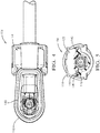
Fig. 5 is a cross section end view of the angled electrical connector assembly ofFig. 1 according to one embodiment of the invention; and -
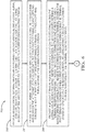
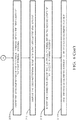
Fig. 6 is a flow chart of a method of manufacturing the angled electrical connector assembly ofFig. 1 according to another embodiment of the invention. - Reference will now be made in detail to embodiments, examples of which are illustrated in the accompanying drawings. In the following detailed description, numerous specific details are set forth in order to provide a thorough understanding of the various described embodiments. However, it will be apparent to one of ordinary skill in the art that the various described embodiments may be practiced without these specific details. In other instances, well-known methods, procedures, components, circuits, and networks have not been described in detail so as not to unnecessarily obscure aspects of the embodiments.
-
Fig. 1 illustrates anelectrical connector system 100 used to interconnect awire cable 102, e.g. a coaxial cable. The illustrated connector system includes a right angledcoaxial connector 104 and a straight matingcoaxial connector 106. The connectors shown inFig. 1 each conform to a FAKRA standard. - As best illustrated in
Figs. 2 and3 , the rightangled connector 104 includes a right angled coaxial electrical terminal, hereinafter referred to as the terminal 108 that has anattachment end 110 extending along a longitudinal axis X configured to be attached to thewire cable 102 and aconnection end 112 extending along a lateral axis Y configured to be attached to a corresponding mating terminal (not shown) contained in themating connector 106. Since this is a right angled terminal, the longitudinal axis X of theattachment end 110 is substantially perpendicular to the lateral axis Y of theconnection end 112. As used herein, substantially perpendicular means ± 5 degrees of absolutely perpendicular. - The terminal 108 is contained within an electrically insulative two part housing. A first terminal housing, hereinafter referred to as the
first housing 114 has afirst cavity 116 that extends along the longitudinal axis X in which theattachment end 110 is disposed. Thefirst cavity 116 defines two openings, acable opening 118 through which thewire cable 102 extends and a terminal extension opening 120 through which theconnection end 112 of the right angled terminal extends. A second terminal housing, hereinafter referred to as thesecond housing 122 has asecond cavity 124 that extends along the lateral axis Y in which theattachment end 110 is disposed. Thesecond cavity 124 also defines two openings, a terminal reception opening 126 through which theconnection end 112 is received and amating opening 128 configured to receive thecorresponding mating connector 106. Thefirst housing 114 defines afirst attachment surface 130 that circumferentially surrounds theterminal extension opening 120. Thesecond housing 122 defines asecond attachment surface 132 that surrounds theterminal reception opening 126. Thefirst attachment surface 130 is sealed to thesecond attachment surface 132, thereby providing a water-tight, preferably hermetic, seal between the first andsecond housings first attachment surface 130 forms a firstacute angle 134 relative to the longitudinal axis X and thesecond attachment surface 132 forms a secondacute angle 136 relative to the lateral axis Y. Since this is a rightangled connector 104, the secondacute angle 136 is complementary to the firstacute angle 134, i.e. the sum of a first angular value of the firstacute angle 134 and a second angular value of the secondacute angle 136 is about 90 degrees. Preferably, the first angular value of the firstacute angle 134 is about 45 degrees and the second angular value of the secondacute angle 136 is about 45 degrees. As used herein, "about" a specific angular value means ± 5 degrees of the recited specific angular value. - The
first attachment surface 130 defines a circumferential ridge, hereafter referred to as theridge 138 that surrounds the terminal extension opening 120 and thesecond attachment surface 132 defines a circumferential groove, hereinafter referred to as thegroove 140, surrounding the terminal reception opening 126 in which theridge 138 is received. Thefirst attachment surface 130 is welded to thesecond attachment surface 132 by welding theupper surface 142 of theridge 138 to thelower surface 144 of thegroove 140 using an infrared laser welding process. Thefirst housing 114 is formed of an infrared absorbent material, such as a polymer that is doped with an infrared absorbing pigment, and thesecond housing 122 is formed of an infrared transparent material, such as polyethylene or polypropylene. When infrared laser energy is applied to the area of theridge 138, the laser energy passes through thesecond housing 122 and is absorbed by theridge 138 of thefirst housing 114, thereby forming a fusedregion 146 between thefirst housing 114 to thesecond housing 122 as shown inFigs 3 ,4, and 5 . Infrared welding systems capable of preforming such infrared laser welding are SIMULTANEOUS THROUGH TRANSMISSION INFRARED® welding systems available from Branson Ultrasonics Corporation of Danbury, Connecticut. - As shown in
Fig. 3 , the rightangled connector 104 also includes acompliant cable seal 148 and acomplaint housing seal 150 to inhibit entry of environmental contaminants, such as water, dust, or electrolytes, into the cavities that may corrode the terminal 108. - In prior designs connector designs, right angled FAKRA compliant connectors had used a one piece housing that contained a two piece terminal shield in order to meet environmental sealing requirements. This configuration was found to be costly and could exhibit unstable connection properties due to the two piece terminal.
- The angled parting line of the two
piece housing angled connector 104 illustrated inFigs. 1-5 provides the benefit of allowing direct insertion of a one-piece terminal shield which provides more reliable connection properties than a two piece terminal. The infrared laser welding of theridge 138 and groove 140 features allow the seam between the first andsecond housings -
Fig. 6 illustrates an example of amethod 200 ofmethod 200 of manufacturing the terminal 108 according to one embodiment of the invention. Themethod 200 includes the following steps: -
STEP 202, PROVIDE AN ELECTRICAL TERMINAL, includes providing a terminal 108 having anattachment end 110 extending along the longitudinal axis X configured to be attached to awire cable 102 and aconnection end 112 extending along the lateral axis Y configured to be attached to a corresponding mating terminal. The longitudinal axis X of theattachment end 110 is substantially perpendicular to the lateral axis Y of theconnection end 112; -
STEP 204, PROVIDE A FIRST TERMINAL HOUSING, includes providing afirst housing 114 having afirst cavity 116 extending along the longitudinal axis X in which theattachment end 110 is disposed, thefirst cavity 116 defining acable opening 118 through which thewire cable 102 extends and defining a terminal extension opening 120 through which theconnection end 112 extends; -
STEP 206, PROVIDE A SECOND TERMINAL HOUSING, includes providing asecond housing 122 having asecond cavity 124 extending along the lateral axis Y in which theattachment end 110 is disposed, thesecond cavity 124 defining a terminal reception opening 126 through which theconnection end 112 is received and amating opening 128 configured to receive thecorresponding mating connector 106, wherein thefirst housing 114 defines afirst attachment surface 130 surrounding the terminal extension opening 120 and thesecond housing 122 defines asecond attachment surface 132 surrounding theterminal reception opening 126; -
STEP 208, INSERT THE ELECTRICAL TERMINAL WITHIN THE FIRST AND SECOND TERMINAL HOUSINGS, includes inserting theattachment end 110 of the terminal 108 within thefirst cavity 116 of thefirst housing 114 and inserting theconnection end 112 of the terminal 108 within thesecond cavity 124 of thesecond housing 122; - The
first attachment surface 130 may define aridge 138 surrounding the terminal extension opening 120 and thesecond attachment surface 132 defines agroove 140 surrounding theterminal reception opening 126.STEP 210, DISPOSE THE RIDGE WITHIN THE GROOVE, is an optional sub-step ofSTEP 202 that includes disposing theridge 138 within thegroove 140; and -
STEP 212, SEAL THE FIRST TERMINAL HOUSING TO THE SECOND TERMINAL HOUSING, includes sealing thefirst attachment surface 130 to thesecond attachment surface 132.STEP 212 may be performed by welding thefirst attachment surface 130 to thesecond attachment surface 132, e.g. by a laser welding process.STEP 212 may be performed by welding theridge 138 to thegroove 140 using an infrared laser welding process. In this case, thefirst housing 114 is formed of first material and thesecond housing 122 is formed of a second material different than the first housing. The first material is substantially infrared transparent and the second material is infrared absorbent. - While the example electrical connector presented herein is a right angled configuration, other embodiments of the invention may be envisioned having an angle between the
attachment end 110 and the connector end of the terminal 108 in a range of 1 to 179 degrees. - While this invention has been described in terms of the preferred embodiments thereof, it is not intended to be so limited, but rather only to the extent set forth in the claims that follow. For example, the above-described embodiments (and/or aspects thereof) may be used in combination with each other. In addition, many modifications may be made to configure a particular situation or material to the teachings of the invention without departing from its scope. Dimensions, types of materials, orientations of the various components, and the number and positions of the various components described herein are intended to define parameters of certain embodiments, and are by no means limiting and are merely prototypical embodiments.
- Many other embodiments and modifications within the spirit and scope of the claims will be apparent to those of skill in the art upon reviewing the above description. The scope of the invention should, therefore, be determined with reference to the following claims, along with the full scope of equivalents to which such claims are entitled.
- As used herein, 'one or more' includes a function being performed by one element, a function being performed by more than one element, e.g., in a distributed fashion, several functions being performed by one element, several functions being performed by several elements, or any combination of the above.
- It will also be understood that, although the terms first, second, etc. are, in some instances, used herein to describe various elements, these elements should not be limited by these terms. These terms are only used to distinguish one element from another. For example, a first contact could be termed a second contact, and, similarly, a second contact could be termed a first contact, without departing from the scope of the various described embodiments. The first contact and the second contact are both contacts, but they are not the same contact.
- The terminology used in the description of the various described embodiments herein is for the purpose of describing particular embodiments only and is not intended to be limiting. As used in the description of the various described embodiments and the appended claims, the singular forms "a", "an" and "the" are intended to include the plural forms as well, unless the context clearly indicates otherwise. It will also be understood that the term "and/or" as used herein refers to and encompasses any and all possible combinations of one or more of the associated listed items. It will be further understood that the terms "includes," "including," "comprises," and/or "comprising," when used in this specification, specify the presence of stated features, integers, steps, operations, elements, and/or components, but do not preclude the presence or addition of one or more other features, integers, steps, operations, elements, components, and/or groups thereof.
- As used herein, the term "if' is, optionally, construed to mean "when" or "upon" or "in response to determining" or "in response to detecting," depending on the context. Similarly, the phrase "if it is determined" or "if [a stated condition or event] is detected" is, optionally, construed to mean "upon determining" or "in response to determining" or "upon detecting [the stated condition or event]" or "in response to detecting [the stated condition or event]," depending on the context.
- Additionally, while terms of ordinance or orientation may be used herein these elements should not be limited by these terms. All terms of ordinance or orientation, unless stated otherwise, are used for purposes distinguishing one element from another, and do not denote any particular order, order of operations, direction or orientation unless stated otherwise.
Claims (15)
- An electrical connector assembly, comprising:an electrical terminal (108) having an attachment end (110) extending along a longitudinal axis (X) configured to be attached to a wire cable (102) and a connection end (112) extending along a lateral axis (Y) configured to be attached to a corresponding mating terminal (108);a first terminal (108) housing having a first cavity (116) extending along the longitudinal axis (X) in which the attachment end (110) is disposed, the first cavity (116) defining a cable opening (118) through which the wire cable (102) extends and defining a terminal extension opening (120) through which the connection end (112) extends; anda second terminal (108) housing having a second cavity (124) extending along the lateral axis (Y) in which the connection end (112) is disposed, the second cavity (124) defining a terminal reception opening (126) through which the connection end (112) is received and a mating opening (128) configured to receive the corresponding mating terminal (108), wherein the first terminal (108) housing defines a first attachment surface (130) surrounding the terminal extension opening (120) and the second terminal (108) housing defines a second attachment surface (132) surrounding the terminal reception opening (126), wherein the first attachment surface (130) is sealed to the second attachment surface (132), and wherein the first attachment surface (130) forms a first angle relative to the longitudinal axis (X) and the second attachment surface (132) forms a second angle relative to the lateral axis (Y).
- The electrical connector assembly according to claim 1, wherein the second angle is complementary to the first angle.
- The electrical connector assembly according to claim 1 or 2, wherein a first angular value of the first angle is about 45 degrees and a second angular value of the second angle is about 45 degrees.
- The electrical connector assembly according to any one of the preceding claims, wherein the first attachment surface (130) defines a circumferential ridge (138) surrounding the terminal extension opening (120) and the second attachment surface (132) defines a circumferential groove (140) surrounding the terminal reception opening (126) in which the circumferential ridge (138) is received.
- The electrical connector assembly according to claim 4, wherein the circumferential ridge (138) is welded to the circumferential groove (140) using an infrared laser welding process.
- The electrical connector assembly according to any one of the preceding claims, wherein the first attachment surface (130) is welded to the second attachment surface (132), thereby forming a watertight joint between the first and second terminal (108) housings.
- The electrical connector assembly according to any one of the preceding claims, wherein the first attachment surface (130) is welded to the second attachment surface (132) using a laser welding process.
- The electrical connector assembly according to any one of the preceding claims, wherein the first terminal (108) housing is formed of first material and the second terminal (108) housing is formed of a second material different than the first terminal (108) housing.
- The electrical connector assembly according to claim 8, wherein the first material is infrared transparent and the second material is infrared absorbent.
- The electrical connector assembly according to any one of the preceding claims, wherein the longitudinal axis (X) of the attachment end (110) is substantially perpendicular to the lateral axis (Y) of the connection end (112).
- A method (200) of manufacturing an electrical connector assembly, comprising the steps of:providing (202) an electrical terminal (108) having an attachment end (110) extending along a longitudinal axis (X) configured to be attached to a wire cable (102) and a connection end (112) extending along a lateral axis (Y) configured to be attached to a corresponding mating terminal (108);providing (204) a first terminal (108) housing having a first cavity (116) extending along the longitudinal axis (X) in which the attachment end (110) is disposed, the first cavity (116) defining a cable opening (118) through which the wire cable (102) extends and defining a terminal extension opening (120) through which the connection end (112) extends;providing (206) a second terminal (108) housing having a second cavity (124) extending along the lateral axis (Y) in which the attachment end (110) is disposed, the second cavity (124) defining a terminal reception opening (126) through which the connection end (112) is received and a mating opening (128) configured to receive the corresponding mating terminal (108), wherein the first terminal (108) housing defines a first attachment surface (130) surrounding the terminal extension opening (120) and the second terminal (108) housing defines a second attachment surface (132) surrounding the terminal reception opening (126);inserting (208) the attachment end (110) of the electrical terminal (108) within the first cavity (116) of the first terminal (108) housing;inserting (212) the connection end (112) of the electrical terminal (108) within the second cavity (124) of the second terminal (108) housing; andsealing (214) the first attachment surface (130) to the second attachment surface (132).
- The method (200) according to claim 11, wherein the first attachment surface (130) defines a circumferential ridge (138) surrounding the terminal extension opening (120) and the second attachment surface (132) defines a circumferential groove (140) surrounding the terminal reception opening (126) and wherein the method (200) further includes the step (210) of disposing the circumferential ridge (138) within the circumferential groove (140).
- The method (200) according to claims 12, wherein the step (214) of sealing the first attachment surface (130) to the second attachment surface (132) is performed by welding the circumferential ridge (138) to the circumferential groove (140) using an infrared laser welding process
- The method (200) according to any one of claims 11-13,
wherein the step (214) of sealing the first attachment surface (130) to the second attachment surface (132) is performed by welding the first attachment surface (130) to the second attachment surface (132),
wherein the welding is performed using a laser welding process. - The method (200) according to any one of claims 11-14,
wherein the first terminal (108) housing is formed of first material and the second terminal (108) housing is formed of a second material different than the first terminal (108) housing,
wherein the first material is infrared transparent and the second material is infrared absorbent.
Applications Claiming Priority (2)
| Application Number | Priority Date | Filing Date | Title |
|---|---|---|---|
| US201862730694P | 2018-09-13 | 2018-09-13 | |
| US16/521,023 US10680380B2 (en) | 2018-09-13 | 2019-07-24 | Angled electrical connector assembly and method of manufacturing same |
Publications (2)
| Publication Number | Publication Date |
|---|---|
| EP3624277A1 true EP3624277A1 (en) | 2020-03-18 |
| EP3624277B1 EP3624277B1 (en) | 2023-12-27 |
Family
ID=67953580
Family Applications (1)
| Application Number | Title | Priority Date | Filing Date |
|---|---|---|---|
| EP19196851.0A Active EP3624277B1 (en) | 2018-09-13 | 2019-09-12 | Angled electrical connector assembly and method of manufacturing same |
Country Status (4)
| Country | Link |
|---|---|
| US (1) | US10680380B2 (en) |
| EP (1) | EP3624277B1 (en) |
| KR (2) | KR102407085B1 (en) |
| CN (1) | CN110896185B (en) |
Cited By (2)
| Publication number | Priority date | Publication date | Assignee | Title |
|---|---|---|---|---|
| DE102020101026A1 (en) | 2020-01-17 | 2021-07-22 | Phoenix Contact Gmbh & Co. Kg | Method for forming a plastic component for an electrical conductor connection terminal system and plastic component produced using the method |
| CN113300151A (en) * | 2021-07-26 | 2021-08-24 | 南通锐莱新能源技术有限公司 | New energy automobile circuit interface processing apparatus |
Families Citing this family (3)
| Publication number | Priority date | Publication date | Assignee | Title |
|---|---|---|---|---|
| CN113437555A (en) * | 2021-07-05 | 2021-09-24 | 华睿(东莞)电子技术有限公司 | Right-angle through-hole connector |
| US12580329B2 (en) | 2022-11-22 | 2026-03-17 | Aptiv Technologies AG | Electrical connector assembly and method of assembling same |
| US12431676B2 (en) | 2023-02-02 | 2025-09-30 | Aptiv Technologies AG | Right angled coaxial electrical connector and method of forming same |
Citations (4)
| Publication number | Priority date | Publication date | Assignee | Title |
|---|---|---|---|---|
| JPS6071083U (en) * | 1983-10-24 | 1985-05-20 | 東洋通信工業株式会社 | plug |
| US7868259B2 (en) * | 2005-06-07 | 2011-01-11 | Siemens Vdo Automotive Ag | Device and method for producing a device |
| JP2012216546A (en) * | 2011-03-31 | 2012-11-08 | Maspro Denkoh Corp | Coaxial plug |
| CN105514671A (en) * | 2016-01-19 | 2016-04-20 | 江苏赛洋机电科技有限公司 | Bent head heavy current cable connector case structure |
Family Cites Families (13)
| Publication number | Priority date | Publication date | Assignee | Title |
|---|---|---|---|---|
| US5035643A (en) * | 1989-05-17 | 1991-07-30 | Zanxx, Inc. | Axial low profile lamp socket assembly |
| US6139334A (en) * | 1998-09-16 | 2000-10-31 | Cooper Automotive Products, Inc. | Integral socket backplate |
| US7604386B2 (en) * | 2005-11-18 | 2009-10-20 | Federal-Mogul World Wide, Inc | Lamp assembly having a socket made from high temperature plastic |
| US7458850B1 (en) * | 2007-05-23 | 2008-12-02 | Corning Gilbert Inc. | Right-angled coaxial cable connector |
| DE102015002832A1 (en) * | 2015-03-05 | 2016-09-08 | Rosenberger Hochfrequenztechnik Gmbh & Co. Kg | Method for mounting an angle connector |
| CN105529562B (en) * | 2016-01-19 | 2018-09-28 | 孙萍 | Elbow single-core cable connector |
| US9762001B2 (en) | 2016-02-01 | 2017-09-12 | Delphi Technologies, Inc. | Right angled coaxial electrical connector and methods for verifying proper assembly thereof |
| US9667000B1 (en) | 2016-06-09 | 2017-05-30 | Delphi Technologies, Inc. | Radio frequency coaxial connector assembly and method of manufacturing same |
| CN205863521U (en) * | 2016-07-07 | 2017-01-04 | 广州勘帝德电子科技有限公司 | Automobile camera head bonnet and wire harness integrated water-proof structure |
| US9960550B2 (en) | 2016-07-25 | 2018-05-01 | Delphi Technologies, Inc. | Coaxial connector assembly |
| CN206412562U (en) * | 2016-12-29 | 2017-08-15 | 浙江永贵电器股份有限公司 | A kind of 90 ° of curved formula terminal shield electric-connectors |
| US9929509B1 (en) | 2017-06-12 | 2018-03-27 | Delphi Technologies, Inc. | Connector system with low profile connector position assurance device |
| US10446950B2 (en) | 2017-06-26 | 2019-10-15 | Delphi Technologies, Llc | Method for forming a shielded electrical terminal and an electrical terminal formed by said method |
-
2019
- 2019-07-24 US US16/521,023 patent/US10680380B2/en active Active
- 2019-09-10 KR KR1020190111860A patent/KR102407085B1/en active Active
- 2019-09-12 EP EP19196851.0A patent/EP3624277B1/en active Active
- 2019-09-12 CN CN201910863598.XA patent/CN110896185B/en active Active
-
2021
- 2021-07-09 KR KR1020210090517A patent/KR102457639B1/en active Active
Patent Citations (4)
| Publication number | Priority date | Publication date | Assignee | Title |
|---|---|---|---|---|
| JPS6071083U (en) * | 1983-10-24 | 1985-05-20 | 東洋通信工業株式会社 | plug |
| US7868259B2 (en) * | 2005-06-07 | 2011-01-11 | Siemens Vdo Automotive Ag | Device and method for producing a device |
| JP2012216546A (en) * | 2011-03-31 | 2012-11-08 | Maspro Denkoh Corp | Coaxial plug |
| CN105514671A (en) * | 2016-01-19 | 2016-04-20 | 江苏赛洋机电科技有限公司 | Bent head heavy current cable connector case structure |
Cited By (2)
| Publication number | Priority date | Publication date | Assignee | Title |
|---|---|---|---|---|
| DE102020101026A1 (en) | 2020-01-17 | 2021-07-22 | Phoenix Contact Gmbh & Co. Kg | Method for forming a plastic component for an electrical conductor connection terminal system and plastic component produced using the method |
| CN113300151A (en) * | 2021-07-26 | 2021-08-24 | 南通锐莱新能源技术有限公司 | New energy automobile circuit interface processing apparatus |
Also Published As
| Publication number | Publication date |
|---|---|
| CN110896185B (en) | 2021-12-31 |
| US20200091650A1 (en) | 2020-03-19 |
| EP3624277B1 (en) | 2023-12-27 |
| KR20200031531A (en) | 2020-03-24 |
| KR20210091083A (en) | 2021-07-21 |
| CN110896185A (en) | 2020-03-20 |
| US10680380B2 (en) | 2020-06-09 |
| KR102407085B1 (en) | 2022-06-10 |
| KR102457639B1 (en) | 2022-10-21 |
Similar Documents
| Publication | Publication Date | Title |
|---|---|---|
| US10680380B2 (en) | Angled electrical connector assembly and method of manufacturing same | |
| US9960550B2 (en) | Coaxial connector assembly | |
| US7530843B1 (en) | Sealed electrical terminal | |
| CN108701948B (en) | Right-angle coaxial electrical connector and method for verifying proper assembly of right-angle coaxial electrical connector | |
| US9667000B1 (en) | Radio frequency coaxial connector assembly and method of manufacturing same | |
| CN102668259B (en) | Two-part contact element for high-voltage plug-and-socket connector | |
| US10886668B1 (en) | Coaxial cable connector assembly | |
| CN101710662B (en) | Connector assemblies with multiple discrete components | |
| US11515660B2 (en) | Electrical connector assembly with retaining device | |
| WO2008144270A1 (en) | Electrical connectors, mating connector assemblies, electrical terminals, and methods for making same | |
| EP3723208B1 (en) | A method for manufacturing a male power terminal, and male power terminal | |
| US9799983B2 (en) | Connector assembly | |
| US20070202739A1 (en) | Coaxial plug connector for a coaxial cable | |
| JP7116040B2 (en) | waterproof shield connector | |
| EP0970546A1 (en) | External ground isolation connector for cable splice closures | |
| US12633695B2 (en) | Male and female power terminal assembly, female and male power terminals | |
| US11515678B2 (en) | Splice connector | |
| US20220384973A1 (en) | Male and female power terminal assembly, female and male power terminals | |
| US12431676B2 (en) | Right angled coaxial electrical connector and method of forming same | |
| EP3376597B1 (en) | Wire to wire connector and method for providing the wire to wire connector | |
| JP2024174345A (en) | Connectors and Wire Harnesses | |
| CN121172496A (en) | Bus connector with insulating housing and sealing mechanism | |
| CN114361896A (en) | Electrical connector assembly and method of making the same |
Legal Events
| Date | Code | Title | Description |
|---|---|---|---|
| PUAI | Public reference made under article 153(3) epc to a published international application that has entered the european phase |
Free format text: ORIGINAL CODE: 0009012 |
|
| STAA | Information on the status of an ep patent application or granted ep patent |
Free format text: STATUS: THE APPLICATION HAS BEEN PUBLISHED |
|
| AK | Designated contracting states |
Kind code of ref document: A1 Designated state(s): AL AT BE BG CH CY CZ DE DK EE ES FI FR GB GR HR HU IE IS IT LI LT LU LV MC MK MT NL NO PL PT RO RS SE SI SK SM TR |
|
| AX | Request for extension of the european patent |
Extension state: BA ME |
|
| STAA | Information on the status of an ep patent application or granted ep patent |
Free format text: STATUS: REQUEST FOR EXAMINATION WAS MADE |
|
| 17P | Request for examination filed |
Effective date: 20200909 |
|
| RBV | Designated contracting states (corrected) |
Designated state(s): AL AT BE BG CH CY CZ DE DK EE ES FI FR GB GR HR HU IE IS IT LI LT LU LV MC MK MT NL NO PL PT RO RS SE SI SK SM TR |
|
| STAA | Information on the status of an ep patent application or granted ep patent |
Free format text: STATUS: EXAMINATION IS IN PROGRESS |
|
| 17Q | First examination report despatched |
Effective date: 20210907 |
|
| GRAP | Despatch of communication of intention to grant a patent |
Free format text: ORIGINAL CODE: EPIDOSNIGR1 |
|
| STAA | Information on the status of an ep patent application or granted ep patent |
Free format text: STATUS: GRANT OF PATENT IS INTENDED |
|
| RAP3 | Party data changed (applicant data changed or rights of an application transferred) |
Owner name: APTIV TECHNOLOGIES LIMITED |
|
| RIC1 | Information provided on ipc code assigned before grant |
Ipc: H01R 24/40 20110101ALN20230301BHEP Ipc: B29C 65/16 20060101ALN20230301BHEP Ipc: H01R 13/52 20060101ALN20230301BHEP Ipc: H01R 13/504 20060101AFI20230301BHEP |
|
| RIC1 | Information provided on ipc code assigned before grant |
Ipc: H01R 24/40 20110101ALN20230306BHEP Ipc: B29C 65/16 20060101ALN20230306BHEP Ipc: H01R 13/52 20060101ALN20230306BHEP Ipc: H01R 13/504 20060101AFI20230306BHEP |
|
| INTG | Intention to grant announced |
Effective date: 20230320 |
|
| GRAJ | Information related to disapproval of communication of intention to grant by the applicant or resumption of examination proceedings by the epo deleted |
Free format text: ORIGINAL CODE: EPIDOSDIGR1 |
|
| STAA | Information on the status of an ep patent application or granted ep patent |
Free format text: STATUS: EXAMINATION IS IN PROGRESS |
|
| GRAS | Grant fee paid |
Free format text: ORIGINAL CODE: EPIDOSNIGR3 |
|
| STAA | Information on the status of an ep patent application or granted ep patent |
Free format text: STATUS: GRANT OF PATENT IS INTENDED |
|
| GRAP | Despatch of communication of intention to grant a patent |
Free format text: ORIGINAL CODE: EPIDOSNIGR1 |
|
| INTC | Intention to grant announced (deleted) | ||
| RIC1 | Information provided on ipc code assigned before grant |
Ipc: H01R 24/40 20110101ALN20230426BHEP Ipc: B29C 65/16 20060101ALN20230426BHEP Ipc: H01R 13/52 20060101ALN20230426BHEP Ipc: H01R 13/504 20060101AFI20230426BHEP |
|
| INTG | Intention to grant announced |
Effective date: 20230511 |
|
| P01 | Opt-out of the competence of the unified patent court (upc) registered |
Effective date: 20230426 |
|
| GRAJ | Information related to disapproval of communication of intention to grant by the applicant or resumption of examination proceedings by the epo deleted |
Free format text: ORIGINAL CODE: EPIDOSDIGR1 |
|
| GRAL | Information related to payment of fee for publishing/printing deleted |
Free format text: ORIGINAL CODE: EPIDOSDIGR3 |
|
| STAA | Information on the status of an ep patent application or granted ep patent |
Free format text: STATUS: EXAMINATION IS IN PROGRESS |
|
| GRAP | Despatch of communication of intention to grant a patent |
Free format text: ORIGINAL CODE: EPIDOSNIGR1 |
|
| INTC | Intention to grant announced (deleted) | ||
| STAA | Information on the status of an ep patent application or granted ep patent |
Free format text: STATUS: GRANT OF PATENT IS INTENDED |
|
| RIC1 | Information provided on ipc code assigned before grant |
Ipc: H01R 24/40 20110101ALN20230828BHEP Ipc: B29C 65/16 20060101ALN20230828BHEP Ipc: H01R 13/52 20060101ALN20230828BHEP Ipc: H01R 13/504 20060101AFI20230828BHEP |
|
| INTG | Intention to grant announced |
Effective date: 20230914 |
|
| GRAA | (expected) grant |
Free format text: ORIGINAL CODE: 0009210 |
|
| STAA | Information on the status of an ep patent application or granted ep patent |
Free format text: STATUS: THE PATENT HAS BEEN GRANTED |
|
| AK | Designated contracting states |
Kind code of ref document: B1 Designated state(s): AL AT BE BG CH CY CZ DE DK EE ES FI FR GB GR HR HU IE IS IT LI LT LU LV MC MK MT NL NO PL PT RO RS SE SI SK SM TR |
|
| REG | Reference to a national code |
Ref country code: GB Ref legal event code: FG4D |
|
| REG | Reference to a national code |
Ref country code: CH Ref legal event code: EP |
|
| REG | Reference to a national code |
Ref country code: DE Ref legal event code: R096 Ref document number: 602019043895 Country of ref document: DE |
|
| REG | Reference to a national code |
Ref country code: IE Ref legal event code: FG4D |
|
| PG25 | Lapsed in a contracting state [announced via postgrant information from national office to epo] |
Ref country code: GR Free format text: LAPSE BECAUSE OF FAILURE TO SUBMIT A TRANSLATION OF THE DESCRIPTION OR TO PAY THE FEE WITHIN THE PRESCRIBED TIME-LIMIT Effective date: 20240328 |
|
| REG | Reference to a national code |
Ref country code: LT Ref legal event code: MG9D |
|
| PG25 | Lapsed in a contracting state [announced via postgrant information from national office to epo] |
Ref country code: LT Free format text: LAPSE BECAUSE OF FAILURE TO SUBMIT A TRANSLATION OF THE DESCRIPTION OR TO PAY THE FEE WITHIN THE PRESCRIBED TIME-LIMIT Effective date: 20231227 |
|
| PG25 | Lapsed in a contracting state [announced via postgrant information from national office to epo] |
Ref country code: ES Free format text: LAPSE BECAUSE OF FAILURE TO SUBMIT A TRANSLATION OF THE DESCRIPTION OR TO PAY THE FEE WITHIN THE PRESCRIBED TIME-LIMIT Effective date: 20231227 |
|
| PG25 | Lapsed in a contracting state [announced via postgrant information from national office to epo] |
Ref country code: LT Free format text: LAPSE BECAUSE OF FAILURE TO SUBMIT A TRANSLATION OF THE DESCRIPTION OR TO PAY THE FEE WITHIN THE PRESCRIBED TIME-LIMIT Effective date: 20231227 Ref country code: GR Free format text: LAPSE BECAUSE OF FAILURE TO SUBMIT A TRANSLATION OF THE DESCRIPTION OR TO PAY THE FEE WITHIN THE PRESCRIBED TIME-LIMIT Effective date: 20240328 Ref country code: FI Free format text: LAPSE BECAUSE OF FAILURE TO SUBMIT A TRANSLATION OF THE DESCRIPTION OR TO PAY THE FEE WITHIN THE PRESCRIBED TIME-LIMIT Effective date: 20231227 Ref country code: ES Free format text: LAPSE BECAUSE OF FAILURE TO SUBMIT A TRANSLATION OF THE DESCRIPTION OR TO PAY THE FEE WITHIN THE PRESCRIBED TIME-LIMIT Effective date: 20231227 Ref country code: BG Free format text: LAPSE BECAUSE OF FAILURE TO SUBMIT A TRANSLATION OF THE DESCRIPTION OR TO PAY THE FEE WITHIN THE PRESCRIBED TIME-LIMIT Effective date: 20240327 |
|
| REG | Reference to a national code |
Ref country code: NL Ref legal event code: MP Effective date: 20231227 |
|
| REG | Reference to a national code |
Ref country code: AT Ref legal event code: MK05 Ref document number: 1645421 Country of ref document: AT Kind code of ref document: T Effective date: 20231227 |
|
| PG25 | Lapsed in a contracting state [announced via postgrant information from national office to epo] |
Ref country code: NL Free format text: LAPSE BECAUSE OF FAILURE TO SUBMIT A TRANSLATION OF THE DESCRIPTION OR TO PAY THE FEE WITHIN THE PRESCRIBED TIME-LIMIT Effective date: 20231227 |
|
| PG25 | Lapsed in a contracting state [announced via postgrant information from national office to epo] |
Ref country code: SE Free format text: LAPSE BECAUSE OF FAILURE TO SUBMIT A TRANSLATION OF THE DESCRIPTION OR TO PAY THE FEE WITHIN THE PRESCRIBED TIME-LIMIT Effective date: 20231227 Ref country code: RS Free format text: LAPSE BECAUSE OF FAILURE TO SUBMIT A TRANSLATION OF THE DESCRIPTION OR TO PAY THE FEE WITHIN THE PRESCRIBED TIME-LIMIT Effective date: 20231227 Ref country code: NO Free format text: LAPSE BECAUSE OF FAILURE TO SUBMIT A TRANSLATION OF THE DESCRIPTION OR TO PAY THE FEE WITHIN THE PRESCRIBED TIME-LIMIT Effective date: 20240327 Ref country code: NL Free format text: LAPSE BECAUSE OF FAILURE TO SUBMIT A TRANSLATION OF THE DESCRIPTION OR TO PAY THE FEE WITHIN THE PRESCRIBED TIME-LIMIT Effective date: 20231227 Ref country code: LV Free format text: LAPSE BECAUSE OF FAILURE TO SUBMIT A TRANSLATION OF THE DESCRIPTION OR TO PAY THE FEE WITHIN THE PRESCRIBED TIME-LIMIT Effective date: 20231227 Ref country code: HR Free format text: LAPSE BECAUSE OF FAILURE TO SUBMIT A TRANSLATION OF THE DESCRIPTION OR TO PAY THE FEE WITHIN THE PRESCRIBED TIME-LIMIT Effective date: 20231227 |
|
| PG25 | Lapsed in a contracting state [announced via postgrant information from national office to epo] |
Ref country code: IS Free format text: LAPSE BECAUSE OF FAILURE TO SUBMIT A TRANSLATION OF THE DESCRIPTION OR TO PAY THE FEE WITHIN THE PRESCRIBED TIME-LIMIT Effective date: 20240427 |
|
| PG25 | Lapsed in a contracting state [announced via postgrant information from national office to epo] |
Ref country code: CZ Free format text: LAPSE BECAUSE OF FAILURE TO SUBMIT A TRANSLATION OF THE DESCRIPTION OR TO PAY THE FEE WITHIN THE PRESCRIBED TIME-LIMIT Effective date: 20231227 Ref country code: AT Free format text: LAPSE BECAUSE OF FAILURE TO SUBMIT A TRANSLATION OF THE DESCRIPTION OR TO PAY THE FEE WITHIN THE PRESCRIBED TIME-LIMIT Effective date: 20231227 |
|
| PG25 | Lapsed in a contracting state [announced via postgrant information from national office to epo] |
Ref country code: SK Free format text: LAPSE BECAUSE OF FAILURE TO SUBMIT A TRANSLATION OF THE DESCRIPTION OR TO PAY THE FEE WITHIN THE PRESCRIBED TIME-LIMIT Effective date: 20231227 |
|
| PG25 | Lapsed in a contracting state [announced via postgrant information from national office to epo] |
Ref country code: SM Free format text: LAPSE BECAUSE OF FAILURE TO SUBMIT A TRANSLATION OF THE DESCRIPTION OR TO PAY THE FEE WITHIN THE PRESCRIBED TIME-LIMIT Effective date: 20231227 Ref country code: SK Free format text: LAPSE BECAUSE OF FAILURE TO SUBMIT A TRANSLATION OF THE DESCRIPTION OR TO PAY THE FEE WITHIN THE PRESCRIBED TIME-LIMIT Effective date: 20231227 Ref country code: RO Free format text: LAPSE BECAUSE OF FAILURE TO SUBMIT A TRANSLATION OF THE DESCRIPTION OR TO PAY THE FEE WITHIN THE PRESCRIBED TIME-LIMIT Effective date: 20231227 Ref country code: IT Free format text: LAPSE BECAUSE OF FAILURE TO SUBMIT A TRANSLATION OF THE DESCRIPTION OR TO PAY THE FEE WITHIN THE PRESCRIBED TIME-LIMIT Effective date: 20231227 Ref country code: IS Free format text: LAPSE BECAUSE OF FAILURE TO SUBMIT A TRANSLATION OF THE DESCRIPTION OR TO PAY THE FEE WITHIN THE PRESCRIBED TIME-LIMIT Effective date: 20240427 Ref country code: EE Free format text: LAPSE BECAUSE OF FAILURE TO SUBMIT A TRANSLATION OF THE DESCRIPTION OR TO PAY THE FEE WITHIN THE PRESCRIBED TIME-LIMIT Effective date: 20231227 Ref country code: CZ Free format text: LAPSE BECAUSE OF FAILURE TO SUBMIT A TRANSLATION OF THE DESCRIPTION OR TO PAY THE FEE WITHIN THE PRESCRIBED TIME-LIMIT Effective date: 20231227 Ref country code: AT Free format text: LAPSE BECAUSE OF FAILURE TO SUBMIT A TRANSLATION OF THE DESCRIPTION OR TO PAY THE FEE WITHIN THE PRESCRIBED TIME-LIMIT Effective date: 20231227 |
|
| PG25 | Lapsed in a contracting state [announced via postgrant information from national office to epo] |
Ref country code: PL Free format text: LAPSE BECAUSE OF FAILURE TO SUBMIT A TRANSLATION OF THE DESCRIPTION OR TO PAY THE FEE WITHIN THE PRESCRIBED TIME-LIMIT Effective date: 20231227 Ref country code: PT Free format text: LAPSE BECAUSE OF FAILURE TO SUBMIT A TRANSLATION OF THE DESCRIPTION OR TO PAY THE FEE WITHIN THE PRESCRIBED TIME-LIMIT Effective date: 20240429 |
|
| PG25 | Lapsed in a contracting state [announced via postgrant information from national office to epo] |
Ref country code: PT Free format text: LAPSE BECAUSE OF FAILURE TO SUBMIT A TRANSLATION OF THE DESCRIPTION OR TO PAY THE FEE WITHIN THE PRESCRIBED TIME-LIMIT Effective date: 20240429 Ref country code: PL Free format text: LAPSE BECAUSE OF FAILURE TO SUBMIT A TRANSLATION OF THE DESCRIPTION OR TO PAY THE FEE WITHIN THE PRESCRIBED TIME-LIMIT Effective date: 20231227 |
|
| REG | Reference to a national code |
Ref country code: DE Ref legal event code: R097 Ref document number: 602019043895 Country of ref document: DE |
|
| PG25 | Lapsed in a contracting state [announced via postgrant information from national office to epo] |
Ref country code: DK Free format text: LAPSE BECAUSE OF FAILURE TO SUBMIT A TRANSLATION OF THE DESCRIPTION OR TO PAY THE FEE WITHIN THE PRESCRIBED TIME-LIMIT Effective date: 20231227 |
|
| PG25 | Lapsed in a contracting state [announced via postgrant information from national office to epo] |
Ref country code: DK Free format text: LAPSE BECAUSE OF FAILURE TO SUBMIT A TRANSLATION OF THE DESCRIPTION OR TO PAY THE FEE WITHIN THE PRESCRIBED TIME-LIMIT Effective date: 20231227 |
|
| PLBE | No opposition filed within time limit |
Free format text: ORIGINAL CODE: 0009261 |
|
| STAA | Information on the status of an ep patent application or granted ep patent |
Free format text: STATUS: NO OPPOSITION FILED WITHIN TIME LIMIT |
|
| 26N | No opposition filed |
Effective date: 20240930 |
|
| PG25 | Lapsed in a contracting state [announced via postgrant information from national office to epo] |
Ref country code: MC Free format text: LAPSE BECAUSE OF FAILURE TO SUBMIT A TRANSLATION OF THE DESCRIPTION OR TO PAY THE FEE WITHIN THE PRESCRIBED TIME-LIMIT Effective date: 20231227 Ref country code: SI Free format text: LAPSE BECAUSE OF FAILURE TO SUBMIT A TRANSLATION OF THE DESCRIPTION OR TO PAY THE FEE WITHIN THE PRESCRIBED TIME-LIMIT Effective date: 20231227 |
|
| REG | Reference to a national code |
Ref country code: DE Ref legal event code: R081 Ref document number: 602019043895 Country of ref document: DE Owner name: APTIV TECHNOLOGIES AG, CH Free format text: FORMER OWNER: APTIV TECHNOLOGIES LIMITED, ST. MICHAEL, BB Ref country code: CH Ref legal event code: PL |
|
| PG25 | Lapsed in a contracting state [announced via postgrant information from national office to epo] |
Ref country code: LU Free format text: LAPSE BECAUSE OF NON-PAYMENT OF DUE FEES Effective date: 20240912 |
|
| REG | Reference to a national code |
Ref country code: BE Ref legal event code: MM Effective date: 20240930 |
|
| PG25 | Lapsed in a contracting state [announced via postgrant information from national office to epo] |
Ref country code: BE Free format text: LAPSE BECAUSE OF NON-PAYMENT OF DUE FEES Effective date: 20240930 |
|
| PG25 | Lapsed in a contracting state [announced via postgrant information from national office to epo] |
Ref country code: CH Free format text: LAPSE BECAUSE OF NON-PAYMENT OF DUE FEES Effective date: 20240930 |
|
| PG25 | Lapsed in a contracting state [announced via postgrant information from national office to epo] |
Ref country code: IE Free format text: LAPSE BECAUSE OF NON-PAYMENT OF DUE FEES Effective date: 20240912 |
|
| PGFP | Annual fee paid to national office [announced via postgrant information from national office to epo] |
Ref country code: DE Payment date: 20250814 Year of fee payment: 7 |
|
| PGFP | Annual fee paid to national office [announced via postgrant information from national office to epo] |
Ref country code: GB Payment date: 20250818 Year of fee payment: 7 |
|
| PGFP | Annual fee paid to national office [announced via postgrant information from national office to epo] |
Ref country code: FR Payment date: 20250812 Year of fee payment: 7 |
|
| PG25 | Lapsed in a contracting state [announced via postgrant information from national office to epo] |
Ref country code: CY Free format text: LAPSE BECAUSE OF FAILURE TO SUBMIT A TRANSLATION OF THE DESCRIPTION OR TO PAY THE FEE WITHIN THE PRESCRIBED TIME-LIMIT; INVALID AB INITIO Effective date: 20190912 |
|
| PG25 | Lapsed in a contracting state [announced via postgrant information from national office to epo] |
Ref country code: HU Free format text: LAPSE BECAUSE OF FAILURE TO SUBMIT A TRANSLATION OF THE DESCRIPTION OR TO PAY THE FEE WITHIN THE PRESCRIBED TIME-LIMIT; INVALID AB INITIO Effective date: 20190912 |