EP3624219A1 - Battery module and busbar assembly thereof - Google Patents
Battery module and busbar assembly thereof Download PDFInfo
- Publication number
- EP3624219A1 EP3624219A1 EP19187029.4A EP19187029A EP3624219A1 EP 3624219 A1 EP3624219 A1 EP 3624219A1 EP 19187029 A EP19187029 A EP 19187029A EP 3624219 A1 EP3624219 A1 EP 3624219A1
- Authority
- EP
- European Patent Office
- Prior art keywords
- region
- connecting portion
- busbar
- battery unit
- main portion
- Prior art date
- Legal status (The legal status is an assumption and is not a legal conclusion. Google has not performed a legal analysis and makes no representation as to the accuracy of the status listed.)
- Granted
Links
Images



Classifications
-
- H—ELECTRICITY
- H01—ELECTRIC ELEMENTS
- H01R—ELECTRICALLY-CONDUCTIVE CONNECTIONS; STRUCTURAL ASSOCIATIONS OF A PLURALITY OF MUTUALLY-INSULATED ELECTRICAL CONNECTING ELEMENTS; COUPLING DEVICES; CURRENT COLLECTORS
- H01R25/00—Coupling parts adapted for simultaneous co-operation with two or more identical counterparts, e.g. for distributing energy to two or more circuits
- H01R25/16—Rails or bus-bars provided with a plurality of discrete connecting locations for counterparts
-
- H—ELECTRICITY
- H01—ELECTRIC ELEMENTS
- H01M—PROCESSES OR MEANS, e.g. BATTERIES, FOR THE DIRECT CONVERSION OF CHEMICAL ENERGY INTO ELECTRICAL ENERGY
- H01M50/00—Constructional details or processes of manufacture of the non-active parts of electrochemical cells other than fuel cells, e.g. hybrid cells
- H01M50/50—Current conducting connections for cells or batteries
- H01M50/528—Fixed electrical connections, i.e. not intended for disconnection
- H01M50/529—Intercell connections through partitions, e.g. in a battery casing
-
- H—ELECTRICITY
- H01—ELECTRIC ELEMENTS
- H01M—PROCESSES OR MEANS, e.g. BATTERIES, FOR THE DIRECT CONVERSION OF CHEMICAL ENERGY INTO ELECTRICAL ENERGY
- H01M50/00—Constructional details or processes of manufacture of the non-active parts of electrochemical cells other than fuel cells, e.g. hybrid cells
- H01M50/20—Mountings; Secondary casings or frames; Racks, modules or packs; Suspension devices; Shock absorbers; Transport or carrying devices; Holders
- H01M50/204—Racks, modules or packs for multiple batteries or multiple cells
- H01M50/207—Racks, modules or packs for multiple batteries or multiple cells characterised by their shape
- H01M50/209—Racks, modules or packs for multiple batteries or multiple cells characterised by their shape adapted for prismatic or rectangular cells
-
- H—ELECTRICITY
- H01—ELECTRIC ELEMENTS
- H01M—PROCESSES OR MEANS, e.g. BATTERIES, FOR THE DIRECT CONVERSION OF CHEMICAL ENERGY INTO ELECTRICAL ENERGY
- H01M50/00—Constructional details or processes of manufacture of the non-active parts of electrochemical cells other than fuel cells, e.g. hybrid cells
- H01M50/50—Current conducting connections for cells or batteries
- H01M50/502—Interconnectors for connecting terminals of adjacent batteries; Interconnectors for connecting cells outside a battery casing
- H01M50/505—Interconnectors for connecting terminals of adjacent batteries; Interconnectors for connecting cells outside a battery casing comprising a single busbar
-
- H—ELECTRICITY
- H01—ELECTRIC ELEMENTS
- H01M—PROCESSES OR MEANS, e.g. BATTERIES, FOR THE DIRECT CONVERSION OF CHEMICAL ENERGY INTO ELECTRICAL ENERGY
- H01M50/00—Constructional details or processes of manufacture of the non-active parts of electrochemical cells other than fuel cells, e.g. hybrid cells
- H01M50/50—Current conducting connections for cells or batteries
- H01M50/502—Interconnectors for connecting terminals of adjacent batteries; Interconnectors for connecting cells outside a battery casing
- H01M50/509—Interconnectors for connecting terminals of adjacent batteries; Interconnectors for connecting cells outside a battery casing characterised by the type of connection, e.g. mixed connections
- H01M50/51—Connection only in series
-
- H—ELECTRICITY
- H01—ELECTRIC ELEMENTS
- H01M—PROCESSES OR MEANS, e.g. BATTERIES, FOR THE DIRECT CONVERSION OF CHEMICAL ENERGY INTO ELECTRICAL ENERGY
- H01M50/00—Constructional details or processes of manufacture of the non-active parts of electrochemical cells other than fuel cells, e.g. hybrid cells
- H01M50/50—Current conducting connections for cells or batteries
- H01M50/502—Interconnectors for connecting terminals of adjacent batteries; Interconnectors for connecting cells outside a battery casing
- H01M50/514—Methods for interconnecting adjacent batteries or cells
- H01M50/517—Methods for interconnecting adjacent batteries or cells by fixing means, e.g. screws, rivets or bolts
-
- H—ELECTRICITY
- H01—ELECTRIC ELEMENTS
- H01M—PROCESSES OR MEANS, e.g. BATTERIES, FOR THE DIRECT CONVERSION OF CHEMICAL ENERGY INTO ELECTRICAL ENERGY
- H01M50/00—Constructional details or processes of manufacture of the non-active parts of electrochemical cells other than fuel cells, e.g. hybrid cells
- H01M50/50—Current conducting connections for cells or batteries
- H01M50/502—Interconnectors for connecting terminals of adjacent batteries; Interconnectors for connecting cells outside a battery casing
- H01M50/521—Interconnectors for connecting terminals of adjacent batteries; Interconnectors for connecting cells outside a battery casing characterised by the material
- H01M50/522—Inorganic material
-
- Y—GENERAL TAGGING OF NEW TECHNOLOGICAL DEVELOPMENTS; GENERAL TAGGING OF CROSS-SECTIONAL TECHNOLOGIES SPANNING OVER SEVERAL SECTIONS OF THE IPC; TECHNICAL SUBJECTS COVERED BY FORMER USPC CROSS-REFERENCE ART COLLECTIONS [XRACs] AND DIGESTS
- Y02—TECHNOLOGIES OR APPLICATIONS FOR MITIGATION OR ADAPTATION AGAINST CLIMATE CHANGE
- Y02E—REDUCTION OF GREENHOUSE GAS [GHG] EMISSIONS, RELATED TO ENERGY GENERATION, TRANSMISSION OR DISTRIBUTION
- Y02E60/00—Enabling technologies; Technologies with a potential or indirect contribution to GHG emissions mitigation
- Y02E60/10—Energy storage using batteries
Definitions
- the present invention relates to the field of battery, and particularly relates to a battery module and a busbar assembly thereof.
- a battery module generally comprises a plurality of batteries and a plurality of busbars, the busbars are connected with the batteries to realize the electrical connection of the batteries.
- the busbar only can connect adjacent batteries, which leads to the connecting sequence of the batteries being invariable and the electrical circuit of the battery module being undiversified, and is difficult to satisfy the requirement of the battery module on diversified electrical circuit.
- an object of the present invention is to provide a battery module and a busbar assembly thereof, which can realize the diversification of an electrical circuit in the battery module, and satisfy the requirement of the battery module on diversified electrical circuit.
- the present invention provides a battery module and a busbar assembly thereof.
- the busbar assembly comprises a first busbar, a second busbar and a first insulator.
- the first busbar comprises a first connecting portion, a second connecting portion and a first main portion, the first connecting portion is capable of being connected to a first battery unit, the second connecting portion is capable of being connected to a second battery unit, the first main portion connects the first connecting portion and the second connecting portion.
- the second busbar comprises a third connecting portion, a fourth connecting portion and a second main portion, the third connecting portion is capable of being connected to a third battery unit, the fourth connecting portion is capable of being connected to a fourth battery unit, the second main portion connects the third connecting portion and the fourth connecting portion.
- the first main portion and the second main portion are partially overlapped with each other, and the first insulator insulates the second main portion and the first main portion.
- the first battery unit, the third battery unit, the second battery unit and the fourth battery unit are capable of being arranged sequentially in a longitudinal direction.
- the first connecting portion, the third connecting portion, the second connecting portion and the fourth connecting portion are sequentially arranged and spaced from each other in the longitudinal direction.
- the first connecting portion and the second connecting portion are positioned at the same side with respect to the first main portion in a transverse direction
- the third connecting portion and the fourth connecting portion are positioned at the same side with respect to the second main portion in the transverse direction.
- the first busbar is provided with a first notch.
- the first notch is positioned above the second main portion in the height direction.
- the first notch is positioned at an end of the first main portion in the longitudinal direction.
- the first busbar further comprises a first extending portion, the first extending portion is provided at a side of the second connecting portion close to the first connecting portion, and the first extending portion connects the second connecting portion and the first main portion.
- the first busbar is further provided with a second notch, the second notch and the first notch are respectively positioned at two ends of the first main portion in the longitudinal direction.
- the first busbar further comprises a second extending portion, the second extending portion is provided at a side of the first connecting portion close to the second connecting portion, and the second extending portion connects the first connecting portion and the first main portion.
- the first main portion comprises a first region, a second region and a third region, the first region, the second region and the third region are arranged sequentially in the longitudinal direction.
- the first region is connected with the first connecting portion
- the third region is connected with the second connecting portion
- the second region is positioned between the first region and the third region.
- the third region and the second main portion are overlapped with each other.
- the second region is arch in shape and protrudes relative to the first region and the third region.
- the second main portion comprises a fourth region, a fifth region and a sixth region, the fourth region, the fifth region and the sixth region are arranged sequentially in the longitudinal direction.
- the sixth region is connected with the fourth connecting portion, the fifth region is connected with the sixth region and bends relative to the sixth region, the fourth region is connected with the fifth region and overlaps the first main portion in the height direction.
- the third connecting portion comprises a seventh region and an eighth region, the seventh region is capable of being connected with the third battery unit, the eighth region is connected with the seventh region and bends relative to the seventh region, the fourth region is connected with the eighth region.
- the second main portion further comprises a ninth region, the ninth region is positioned between the fourth region and the fifth region.
- the second main portion is arch in shape and protrudes relative to the fourth region.
- the battery module comprises a first battery unit, a second battery unit, a third battery unit, a fourth battery unit and the busbar assembly.
- the first battery unit, the third battery unit, the second battery unit and the fourth battery unit are arranged sequentially in a longitudinal direction.
- the first connecting portion is connected with the first battery unit, the second connecting portion is connected with the second battery unit.
- the third connecting portion is connected with the third battery unit, the fourth connecting portion is connected with the fourth battery unit.
- the busbar can connect batteries between which other battery is interposed, and by allowing the busbars to reasonably cooperate with each other, it can realize the diversification of an electrical circuit in the battery module, satisfy the requirement of the battery module on diversified electrical circuit.
- the terms “first”, “second”, “third” and the like are only used for illustrative purposes and are not to be construed as expressing or implying a relative importance.
- the term “plurality” is two or more.
- the term “connect” should be broadly interpreted, for example, the term “connect” can be “fixedly connect”, “detachably connect”, “integrally connect”, “electrically connect” or “signal connect”.
- the term “connect” also can be “directly connect” or “indirectly connect via a medium”.
- a battery module comprises a battery 1, a busbar assembly 2, an end plate 3, a side plate 4 and a wiring harness assembly 5.
- the battery 1 may be a prismatic lithium-ion battery, and have two electrode terminals protruding from the top thereof, that is a positive electrode terminal T1 and a negative electrode terminal T2.
- the battery 1 is provided as plurality in number and the batteries 1 are sequentially arranged in a longitudinal direction Y.
- the end plate 3 is provided as two in number and the two end plates 3 are respectively provided to two ends of the batteries 1 in the longitudinal direction Y
- the side plate 4 is provided as two in number and the two side plates 4 are respectively provided to two sides of the batteries 1 in a transverse direction X
- the end plates 3 and the side plates 4 are welded together to form a rectangular frame.
- the batteries 1 can be fixed with the frame by bonding and the like.
- the wiring harness assembly 5 is provided above the batteries 1.
- the busbar assembly 2 is fixed with the wiring harness assembly 5 and comprises a plurality of busbars, the busbars electrically connect the batteries 1, so as to realize the charge and the discharge of the battery module.
- the wiring harness assembly 5 can collect the information of each battery 1 via the busbars, such as the electric current, the voltage and the like.
- the batteries 1 can be divided into a plurality of battery units, each battery unit comprises at least one battery 1.
- the plurality of battery units can be same with each other or different with each other in the number of the battery 1.
- each battery unit comprises one battery 1.
- the busbar assembly 2 comprises a first busbar 21, a second busbar 22 and a first insulator 23.
- the first busbar 21 comprises a first connecting portion 211, a second connecting portion 212 and a first main portion 213, the first connecting portion 211 may be connected to a first battery unit 11 by welding, the second connecting portion 212 may be connected to a second battery unit 12 by welding, the first main portion 213 connects the first connecting portion 211 and the second connecting portion 212.
- the first busbar 21 may be an integral metal member in the shape of plate.
- both of the first battery unit 11 and the second battery unit 12 each comprise one battery 1.
- the first connecting portion 211 may be connected with the positive electrode terminal T1 of the battery 1 of the first battery unit 11; the second connecting portion 212 may be connected with the negative electrode terminal T2 of the battery 1 of the second battery unit 12. Because the first main portion 213 connects the first connecting portion 211 and the second connecting portion 212, the first busbar 21 connects the first battery unit 11 and the second battery unit 12 in series.
- both of the first battery unit 11 and the second battery unit 12 each comprises a plurality of batteries 1 arranged sequentially in the longitudinal direction Y.
- the first connecting portion 211 may be connected with the positive electrode terminals T1 of the plurality of batteries 1 of the first battery unit 11, so as to connect the plurality of batteries 1 of the first battery unit 11 in parallel; the second connecting portion 212 may be connected with the negative electrode terminals T2 of the plurality of batteries 1 of the second battery unit 12, so as to connect the plurality of batteries 1 of the second battery unit 12 in parallel. Because the first main portion 213 connects the first connecting portion 211 and the second connecting portion 212, the first busbar 21 connects the first battery unit 11 and the second battery unit 12 in series.
- the second busbar 22 comprises a third connecting portion 221, a fourth connecting portion 222 and a second main portion 223, the third connecting portion 221 may be connected to a third battery unit 13 by welding, the fourth connecting portion 222 may be connected to a fourth battery unit 14 by welding, the second main portion 223 connects the third connecting portion 221 and the fourth connecting portion 222.
- the second busbar 22 may be an integral metal member in the shape of plate.
- both of the third battery unit 13 and the fourth battery unit 14 each comprise one battery 1.
- the third connecting portion 221 may be connected with the negative electrode terminal T2 of the battery 1 of the third battery unit 13
- the fourth connecting portion 222 may be connected with the positive electrode terminal T1 of the battery 1 of the fourth battery unit 14. Because the second main portion 223 connects the third connecting portion 221 and the fourth connecting portion 222, the second busbar 22 connects the third battery unit 13 and the fourth battery unit 14 in series.
- the first battery unit 11, the third battery unit 13, the second battery unit 12 and the fourth battery unit 14 are arranged sequentially in the longitudinal direction Y, so that the first main portion 213 extends to cross the third battery unit 13, the second main portion 223 extends to cross the second battery unit 12.
- the first main portion 213 and the second main portion 223 are preferably arranged up and down in a height direction Z.
- the first main portion 213 and the second main portion 223 will be partially overlapped with each other in the height direction Z, and there is a risk that the first main portion 213 and the second main portion 223 contact with each other.
- the present invention can insulate the first main portion 213 from the second main portion 223, and avoid an electrical connection between the first busbar 21 and the second busbar 22.
- an edge of the first insulator 23 should be beyond an overlapped region between the second main portion 223 and the first main portion 213; preferably, the edge of the first insulator 23 is beyond the overlapped region by at least 2mm.
- the first insulator 23 functions for insulation, compression resistance, bonding and polymerization, and two surfaces of the first insulator 23 are respectively bonded to the first main portion 213 and the second main portion 223.
- the busbar assembly 2 further comprises a plurality of third busbars 25, the first busbar 21, the second busbar 22 and the third busbars 25 connect all the batteries 1 together.
- the busbar can connect batteries 1 between which other battery is interposed, and by allowing the busbars to reasonably cooperate with each other, it can realize the diversification of an electrical circuit in the battery module, satisfy the requirement of the battery module on diversified electrical circuit.
- busbars By allowing the busbars to reasonably cooperate with each other, it further can position a positive output electrode and a negative output electrode at the same side, realize the output of the battery module at the same side, and simplify a connecting structure between battery modules.
- the first connecting portion 211, the third connecting portion 221, the second connecting portion 212 and the fourth connecting portion 222 are sequentially arranged and spaced from each other in the longitudinal direction Y, a distance between every two adjacent portions is at least beyond 2mm, so as to satisfy the requirement of creepage distance and electric clearance.
- the first connecting portion 211 and the second connecting portion 212 are positioned at the same side with respect to the first main portion 213 in the transverse direction X
- the third connecting portion 221 and the fourth connecting portion 222 are positioned at the same side with respect to the second main portion 223 in the transverse direction X.
- busbar assembly 2 of the present invention will be described in combination with different embodiments.
- the first busbar 21 and the second busbar 22 can have similar structures.
- the first busbar 21 and the second busbar 22 can be arranged up and down in the height direction Z.
- the first busbar 21 is provided above the second busbar 22; certainly, in an alternative embodiment, the first busbar 21 also can be provided below the second busbar 22.
- the first main portion 213 is positioned above the second main portion 223. Because the second main portion 223 is position below the first main portion 213, when the second main portion 223 crosses the second battery unit 12, it may contact the battery 1 (especially the electrode terminal) of the second battery unit 12.
- a second insulator 24 is bonded on a surface of the second main portion 223 close to the battery 1 of the second battery unit 12, and the second insulator 24 can insulate the second main portion 223 from the battery 1 of the second battery unit 12.
- the batteries 1 have same specifications, so distances between electrode terminals of every two adjacent batteries 1 are equal.
- an overall length of the first busbar 21 is generally equal to an overall length of the second busbar 22.
- two ends of the second main portion 223 in the longitudinal direction Y are respectively flush with an outer end of the third connecting portion 221 and an outer end of the fourth connecting portion 222; in other words, in the longitudinal direction Y, a length of the second main portion 223 is equal to an overall length of the second busbar 22.
- two ends of the first main portion 213 in the longitudinal direction Y are respectively flush with an outer end of the first connecting portion 211 and an outer end of the second connecting portion 212.
- a second embodiment of the present invention is substantially the same as the first embodiment, and the difference between the two embodiments lies in a structure of the first busbar 21.
- the first busbar 21 is provided with a first notch 214, the first notch 214 can shorten heat transfer path and reduce an amount of heat generated in the first busbar 21.
- the first main portion 213 and the second main portion 223 are partially overlapped with each other in the height direction Z, and the heat is prone to be accumulated in the overlapped region; the first insulator 23 is positioned between the second main portion 223 and the first main portion 213, if the temperature rises excessively, the first insulator 23 is prone to be burnt out easily, thereby leading to failure of insulation.
- an area of the overlapped region between the first main portion 213 and the second main portion 223 is large, the dissipating efficiency of heat is low, and the heat is more prone to be accumulated.
- the first busbar 21 of the second embodiment is provided with the first notch 214, and the first notch 214 is positioned above or below the second main portion 223 in the height direction Z.
- the first notch 214 can increase an exposed area of the first insulator 23 or an exposed area of the second main portion 223, provide heat dissipating passage for the second main portion 223 and the first insulator 23, improve dissipating efficiency of heat, reduce accumulation of heat.
- the first busbar 21 is provided above the second busbar 22, correspondingly, in the height direction Z, both of the first main portion 213 and the first notch 214 are positioned above the second main portion 223.
- the battery 1 generates heat in the process of work, so the temperature of the space below the busbar assembly 2 is generally higher than the temperature of the space above the busbar assembly 2.
- a position of the first notch 214 can be determined depending on requirement. If the first notch 214 is directly provided to an interior of the first main portion 213, it will decrease the overcurrent area of the first main portion 213 in the position of the first notch 214. Therefore, preferably, the first notch 214 is positioned at an end of the first main portion 213 in the longitudinal direction Y, the first main portion 213 and the second connecting portion 212 form boundaries of the first notch 214. At this time, the first notch 214 only decreases an overall length of the first main portion 213 in the longitudinal direction Y, but will not affect the overcurrent area of the first main portion 213.
- the first busbar 21 of the second embodiment is provided with the first notch 214, and the first notch 214 will decrease an overcurrent area of the connecting position between the first main portion 213 and the second connecting portion 212, affect the overcurrent capability of the first busbar 21. Therefore, preferably, the first busbar 21 of the second embodiment further comprises a first extending portion 216, the first extending portion 216 is provided at a side of the second connecting portion 212 close to the first connecting portion 211, and the first extending portion 216 connects the second connecting portion 212 and the first main portion 213.
- the first extending portion 216 can have a function of adapter, thereby increasing the overcurrent area between the first main portion 213 and the second connecting portion 212, ensuring the overcurrent capability of the first busbar 21.
- the first busbar 21 is further provided with a second notch 215, the first notch 214 and the second notch 215 are respectively positioned at two ends of the first main portion 213 in the longitudinal direction Y.
- the first main portion 213 and the first connecting portion 211 form boundaries of the second notch 215.
- the second notch 215 does not decrease the area of the overlapping region between the first main portion 213 and the second main portion 223, it can shorten the heat transfer path and reduce an amount of heat generated.
- the second notch 215 also decreases an area of the connecting position between the first main portion 213 and the first connecting portion 211, affects the overcurrent capability of the first busbar 21. Therefore, preferably, the first busbar 21 further comprises a second extending portion 217, the second extending portion 217 is provided at a side of the first connecting portion 211 close to the second connecting portion 212, and the second extending portion 217 connects the first connecting portion 211 and the first main portion 213.
- the first connecting portion 211, the second extending portion 217 and the first main portion 213 form a bending structure in the shape of "Z"; similarly, the second connecting portion 212, the first extending portion 216 and the first main portion 213 form a bending structure in the shape of "Z".
- the batteries 1 will swell; if the batteries 1 swell, a stretching stress will be applied to the first busbar 21 and the second busbar 22.
- the first busbar 21 of the second embodiment having the bending structure in the shape of "Z” helps dispersal of stress, and is not prone to fracture in bending position.
- the first main portion 213 comprises a first region 213A, a second region 213B and a third region 213C, the first region 213A, the second region 213B and the third region 213C are arranged sequentially in the longitudinal direction Y; the first region 213A is connected with the first connecting portion 211, the third region 213C is connected with the second connecting portion 212, the second region 213B is positioned between the first region 213A and the third region 213C.
- the third region 213C and the second main portion 223 are overlapped with each other; in the longitudinal direction Y, both of the first region 213A and the second region 213B are positioned outside the second main portion 223.
- the batteries 1 need to be stacked sequentially; a height difference may exist among the batteries 1 in the height direction Z due to assembling errors.
- the first busbar 21 needs to be welded to the first battery unit 11 and the second battery unit 12 at the same time, when a height difference exists between the first battery unit 11 and the second battery unit 12, the first connecting portion 211 and the second connecting portion 212 can not be attached to the electrode terminals at the same time, which is prone to lead to poor welding.
- the second region 213B is preferably arch in shape
- the first busbar 21 can bend in the position of the second region 213B, so even if the height difference exists between the first battery unit 11 and the second battery unit 12, it also can ensure that the first connecting portion 211 and the second connecting portion 212 are attached to the electrode terminals at the same time, and avoid poor welding.
- the second region 213B which is arch in shape can be deformed under the affect of the stretching stress, thereby absorbing stress, avoiding the first busbar 21 being fractured.
- the second region 213B is positioned outside the second main portion 223, the second region 213B can protrude downwardly relative to the first region 213A and the third region 213C.
- an overall height of the busbar assembly 2 does not increase, thereby sufficiently making use of the space.
- the second region 213B can be provided as one in number; certainly, as long as the space permits, the second region 213B also can be provided as plurality in number, and the plurality of the second regions 213B are arranged in the longitudinal direction Y.
- the electrode terminals of all batteries 1 should be flush with each other, so all of the first connecting portion 211, the second connecting portion 212, the third connecting portion 221 and the fourth connecting portion 222 should be positioned in a plane. Because the first busbar 21 and the second busbar 22 are arranged up and down in the height direction Z, the first busbar 21 or the second busbar 22 needs to be bent, so as to position the first connecting portion 211, the second connecting portion 212, the third connecting portion 221 and the fourth connecting portion 222 in the plane.
- the second main portion 223 comprises a fourth region 223A, a fifth region 223B and a sixth region 223C, the fourth region 223A, the fifth region 223B and the sixth region 223C are arranged sequentially in the longitudinal direction Y.
- the sixth region 223C is connected with the fourth connecting portion 222
- the fifth region 223B is connected with the sixth region 223C and bends downwardly relative to the sixth region 223C
- the fourth region 223A is connected with the fifth region 223B and overlaps the first main portion 213 in the height direction Z.
- the third connecting portion 221 comprises a seventh region 221A and an eighth region 221B, the seventh region 221A is connected with the third battery unit 13, the eighth region 221B is connected with the seventh region 221A and bends downwardly relative to the seventh region 221A, the fourth region 223A is connected with the eighth region 221B.
- the seventh region 221A is in the shape of flat plate and flush with the first connecting portion 211.
- the first insulator 23 further covers the eighth region 221B, so as to avoid the eighth region 221B contacting the first main portion 213.
- the second main portion 223 further comprises a ninth region 223D which is arch in shape, the ninth region 223D is positioned between the fourth region 223A and the fifth region 223B.
- the function of the ninth region 223D of the second main portion 223 is the same as the function of the second region 213B of the first main portion 213, which is used for absorbing the height difference between the batteries 1 and the swelling stress of the batteries 1.
- the ninth region 223D may be directly connected with the fifth region 223B, the ninth region 223D and the fifth region 223B form a continuously bending structure, thus the fifth region 223B also can be used for absorbing the height difference between the batteries 1 and the swelling stress of the batteries 1.
- the ninth region 223D preferably protrudes upwardly relative to the fourth region 223A, thus the overall height of the busbar assembly 2 will not increase, thereby sufficiently making use of the space.
- the ninth region 223D can be provided as one in number; certainly, as long as the space permits, the ninth region 223D also can be provided as plurality in number, and the plurality of ninth regions 223D are arranged in the longitudinal direction Y.
- all of the first connecting portion 211, the second connecting portion 212, the third connecting portion 221 and the fourth connecting portion 222 each are provided with a recognizing hole for positioning during welding.
- a plurality of recessed portions P may be formed in the first main portion 213 and the second main portion 223 by stamping.
- the wiring harness assembly 5 is provided with protrusions, the protrusions extend into one recessed portion P of the first main portion 213 and one recessed portion P of the second main portion 223, thereby fixing the first busbar 21 and the second busbar 22 to the wiring harness assembly 5.
- the wiring harness assembly 5 also can be connected to another recessed portion P of the first main portion 213 and another recessed portion P of the second main portion 223 by nickel pieces, the nickel pieces can transmit the information, such as electric current and voltage of the batteries 1, to the wiring harness assembly 5.
Landscapes
- Chemical & Material Sciences (AREA)
- Chemical Kinetics & Catalysis (AREA)
- Electrochemistry (AREA)
- General Chemical & Material Sciences (AREA)
- Inorganic Chemistry (AREA)
- Connection Of Batteries Or Terminals (AREA)
- Battery Mounting, Suspending (AREA)
Abstract
Description
- The present application claims priority to Chinese patent application No.
CN201811075009.3, filed on September 14, 2018 - The present invention relates to the field of battery, and particularly relates to a battery module and a busbar assembly thereof.
- A battery module generally comprises a plurality of batteries and a plurality of busbars, the busbars are connected with the batteries to realize the electrical connection of the batteries. However, in the existing battery module, the busbar only can connect adjacent batteries, which leads to the connecting sequence of the batteries being invariable and the electrical circuit of the battery module being undiversified, and is difficult to satisfy the requirement of the battery module on diversified electrical circuit.
- In view of the problem existing in the background, an object of the present invention is to provide a battery module and a busbar assembly thereof, which can realize the diversification of an electrical circuit in the battery module, and satisfy the requirement of the battery module on diversified electrical circuit.
- In order to achieve the above object, the present invention provides a battery module and a busbar assembly thereof.
- The busbar assembly comprises a first busbar, a second busbar and a first insulator. The first busbar comprises a first connecting portion, a second connecting portion and a first main portion, the first connecting portion is capable of being connected to a first battery unit, the second connecting portion is capable of being connected to a second battery unit, the first main portion connects the first connecting portion and the second connecting portion. The second busbar comprises a third connecting portion, a fourth connecting portion and a second main portion, the third connecting portion is capable of being connected to a third battery unit, the fourth connecting portion is capable of being connected to a fourth battery unit, the second main portion connects the third connecting portion and the fourth connecting portion. In a height direction, the first main portion and the second main portion are partially overlapped with each other, and the first insulator insulates the second main portion and the first main portion. The first battery unit, the third battery unit, the second battery unit and the fourth battery unit are capable of being arranged sequentially in a longitudinal direction.
- The first connecting portion, the third connecting portion, the second connecting portion and the fourth connecting portion are sequentially arranged and spaced from each other in the longitudinal direction. The first connecting portion and the second connecting portion are positioned at the same side with respect to the first main portion in a transverse direction, the third connecting portion and the fourth connecting portion are positioned at the same side with respect to the second main portion in the transverse direction.
- The first busbar is provided with a first notch. The first notch is positioned above the second main portion in the height direction.
- The first notch is positioned at an end of the first main portion in the longitudinal direction. The first busbar further comprises a first extending portion, the first extending portion is provided at a side of the second connecting portion close to the first connecting portion, and the first extending portion connects the second connecting portion and the first main portion.
- The first busbar is further provided with a second notch, the second notch and the first notch are respectively positioned at two ends of the first main portion in the longitudinal direction. The first busbar further comprises a second extending portion, the second extending portion is provided at a side of the first connecting portion close to the second connecting portion, and the second extending portion connects the first connecting portion and the first main portion.
- The first main portion comprises a first region, a second region and a third region, the first region, the second region and the third region are arranged sequentially in the longitudinal direction. The first region is connected with the first connecting portion, the third region is connected with the second connecting portion, the second region is positioned between the first region and the third region. In the height direction, the third region and the second main portion are overlapped with each other. The second region is arch in shape and protrudes relative to the first region and the third region.
- The second main portion comprises a fourth region, a fifth region and a sixth region, the fourth region, the fifth region and the sixth region are arranged sequentially in the longitudinal direction. The sixth region is connected with the fourth connecting portion, the fifth region is connected with the sixth region and bends relative to the sixth region, the fourth region is connected with the fifth region and overlaps the first main portion in the height direction. The third connecting portion comprises a seventh region and an eighth region, the seventh region is capable of being connected with the third battery unit, the eighth region is connected with the seventh region and bends relative to the seventh region, the fourth region is connected with the eighth region.
- The second main portion further comprises a ninth region, the ninth region is positioned between the fourth region and the fifth region. The second main portion is arch in shape and protrudes relative to the fourth region.
- The battery module comprises a first battery unit, a second battery unit, a third battery unit, a fourth battery unit and the busbar assembly. The first battery unit, the third battery unit, the second battery unit and the fourth battery unit are arranged sequentially in a longitudinal direction. The first connecting portion is connected with the first battery unit, the second connecting portion is connected with the second battery unit. The third connecting portion is connected with the third battery unit, the fourth connecting portion is connected with the fourth battery unit.
- The present invention has the following beneficial effects: in the battery module of the present invention, the busbar can connect batteries between which other battery is interposed, and by allowing the busbars to reasonably cooperate with each other, it can realize the diversification of an electrical circuit in the battery module, satisfy the requirement of the battery module on diversified electrical circuit.
-
-
FIG. 1 is a schematic view of a battery module according to the present invention. -
FIG. 2 is a schematic view of a battery and a busbar assembly connected together according to the present invention. -
FIG. 3 is a schematic view of an embodiment of the busbar assembly according to the present invention. -
FIG. 4 is an exploded view of the busbar assembly ofFIG. 3 . -
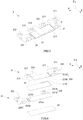
FIG. 5 is a schematic view of another embodiment of the busbar assembly according to the present invention. -
FIG. 6 is an exploded view of the busbar assembly ofFIG. 5 . -
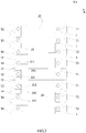
FIG. 7 is a top view of the busbar assembly ofFIG. 5 . - Reference numerals in figures are represented as follows:
- 1 battery
- 11 first battery unit
- 12 second battery unit
- 13 third battery unit
- 14 fourth battery unit
- 2 busbar assembly
- 21 first busbar
- 211 first connecting portion
- 212 second connecting portion
- 213 first main portion
- 213A first region
- 213B second region
- 213C third region
- 214 first notch
- 215 second notch
- 216 first extending portion
- 217 second extending portion
- 22 second busbar
- 221 third connecting portion
- 221A seventh region
- 221B eighth region
- 222 fourth connecting portion
- 223 second main portion
- 223A fourth region
- 223B fifth region
- 223C sixth region
- 223D ninth region
- 23 first insulator
- 24 second insulator
- 25 third busbar
- 221 third connecting portion
- 21 first busbar
- 3 end plate
- 4 side plate
- 5 wiring harness assembly
- T1 positive electrode terminal
- T2 negative electrode terminal
- P recessed portion
- X transverse direction
- Y longitudinal direction
- Z height direction
- To make the object, technical solutions and advantages of the present invention more apparent, hereinafter the present invention will be further described in detail in combination with the accompanying figures and the embodiments. It should be understood that the specific embodiments described herein are merely used to explain the present invention but are not intended to limit the present invention.
- In the description of the present invention, unless otherwise specifically defined and limited, the terms "first", "second", "third" and the like are only used for illustrative purposes and are not to be construed as expressing or implying a relative importance. The term "plurality" is two or more. Unless otherwise defined or described, the term "connect" should be broadly interpreted, for example, the term "connect" can be "fixedly connect", "detachably connect", "integrally connect", "electrically connect" or "signal connect". The term "connect" also can be "directly connect" or "indirectly connect via a medium". For the persons skilled in the art, the specific meanings of the abovementioned terms in the present invention can be understood according to the specific situation.
- In the description of the present invention, it should be understood that spatially relative terms, such as "above", "below" and the like, are described based on orientations illustrated in the figures, but are not intended to limit the embodiments of the present invention. Hereinafter the present invention will be further described in detail in combination with the exemplary embodiments and the figures.
- Referring to
FIG. 1 andFIG. 2 , a battery module comprises abattery 1, abusbar assembly 2, anend plate 3, aside plate 4 and awiring harness assembly 5. - The
battery 1 may be a prismatic lithium-ion battery, and have two electrode terminals protruding from the top thereof, that is a positive electrode terminal T1 and a negative electrode terminal T2. Thebattery 1 is provided as plurality in number and thebatteries 1 are sequentially arranged in a longitudinal direction Y. Theend plate 3 is provided as two in number and the twoend plates 3 are respectively provided to two ends of thebatteries 1 in the longitudinal direction Y, theside plate 4 is provided as two in number and the twoside plates 4 are respectively provided to two sides of thebatteries 1 in a transverse direction X, theend plates 3 and theside plates 4 are welded together to form a rectangular frame. Thebatteries 1 can be fixed with the frame by bonding and the like. Thewiring harness assembly 5 is provided above thebatteries 1. Thebusbar assembly 2 is fixed with thewiring harness assembly 5 and comprises a plurality of busbars, the busbars electrically connect thebatteries 1, so as to realize the charge and the discharge of the battery module. Thewiring harness assembly 5 can collect the information of eachbattery 1 via the busbars, such as the electric current, the voltage and the like. - In the battery module of the present invention, the
batteries 1 can be divided into a plurality of battery units, each battery unit comprises at least onebattery 1. The plurality of battery units can be same with each other or different with each other in the number of thebattery 1. In an embodiment, referring toFIG. 2 , each battery unit comprises onebattery 1. - Referring to
FIG. 2 andFIG. 3 , thebusbar assembly 2 comprises afirst busbar 21, asecond busbar 22 and afirst insulator 23. - The
first busbar 21 comprises a first connectingportion 211, a second connectingportion 212 and a firstmain portion 213, the first connectingportion 211 may be connected to afirst battery unit 11 by welding, the second connectingportion 212 may be connected to asecond battery unit 12 by welding, the firstmain portion 213 connects the first connectingportion 211 and the second connectingportion 212. Thefirst busbar 21 may be an integral metal member in the shape of plate. - In an embodiment, both of the
first battery unit 11 and thesecond battery unit 12 each comprise onebattery 1. Referring toFIG. 2 , the first connectingportion 211 may be connected with the positive electrode terminal T1 of thebattery 1 of thefirst battery unit 11; the second connectingportion 212 may be connected with the negative electrode terminal T2 of thebattery 1 of thesecond battery unit 12. Because the firstmain portion 213 connects the first connectingportion 211 and the second connectingportion 212, thefirst busbar 21 connects thefirst battery unit 11 and thesecond battery unit 12 in series. Alternatively, in another embodiment, both of thefirst battery unit 11 and thesecond battery unit 12 each comprises a plurality ofbatteries 1 arranged sequentially in the longitudinal direction Y. The first connectingportion 211 may be connected with the positive electrode terminals T1 of the plurality ofbatteries 1 of thefirst battery unit 11, so as to connect the plurality ofbatteries 1 of thefirst battery unit 11 in parallel; the second connectingportion 212 may be connected with the negative electrode terminals T2 of the plurality ofbatteries 1 of thesecond battery unit 12, so as to connect the plurality ofbatteries 1 of thesecond battery unit 12 in parallel. Because the firstmain portion 213 connects the first connectingportion 211 and the second connectingportion 212, thefirst busbar 21 connects thefirst battery unit 11 and thesecond battery unit 12 in series. - The
second busbar 22 comprises a third connectingportion 221, a fourth connectingportion 222 and a secondmain portion 223, the third connectingportion 221 may be connected to athird battery unit 13 by welding, the fourth connectingportion 222 may be connected to afourth battery unit 14 by welding, the secondmain portion 223 connects the third connectingportion 221 and the fourth connectingportion 222. Thesecond busbar 22 may be an integral metal member in the shape of plate. - In an embodiment, both of the
third battery unit 13 and thefourth battery unit 14 each comprise onebattery 1. Referring toFIG. 2 , the third connectingportion 221 may be connected with the negative electrode terminal T2 of thebattery 1 of thethird battery unit 13, the fourth connectingportion 222 may be connected with the positive electrode terminal T1 of thebattery 1 of thefourth battery unit 14. Because the secondmain portion 223 connects the third connectingportion 221 and the fourth connectingportion 222, thesecond busbar 22 connects thethird battery unit 13 and thefourth battery unit 14 in series. - In the battery module, the
first battery unit 11, thethird battery unit 13, thesecond battery unit 12 and thefourth battery unit 14 are arranged sequentially in the longitudinal direction Y, so that the firstmain portion 213 extends to cross thethird battery unit 13, the secondmain portion 223 extends to cross thesecond battery unit 12. - In order to save the space occupied by the
first busbar 21 and thesecond busbar 22 in the transverse direction X and assemble thefirst busbar 21 and thesecond busbar 22 easily, the firstmain portion 213 and the secondmain portion 223 are preferably arranged up and down in a height direction Z. When the firstmain portion 213 and the secondmain portion 223 are arranged up and down, the firstmain portion 213 and the secondmain portion 223 will be partially overlapped with each other in the height direction Z, and there is a risk that the firstmain portion 213 and the secondmain portion 223 contact with each other. By providing thefirst insulator 23 between thefirst busbar 21 and thesecond busbar 22, the present invention can insulate the firstmain portion 213 from the secondmain portion 223, and avoid an electrical connection between thefirst busbar 21 and thesecond busbar 22. - In order to satisfy the requirement of the creepage distance and the electric clearance between the
first busbar 21 and thesecond busbar 22, an edge of thefirst insulator 23 should be beyond an overlapped region between the secondmain portion 223 and the firstmain portion 213; preferably, the edge of thefirst insulator 23 is beyond the overlapped region by at least 2mm. Thefirst insulator 23 functions for insulation, compression resistance, bonding and polymerization, and two surfaces of thefirst insulator 23 are respectively bonded to the firstmain portion 213 and the secondmain portion 223. - Referring to
FIG. 1 andFIG. 2 , thebusbar assembly 2 further comprises a plurality ofthird busbars 25, thefirst busbar 21, thesecond busbar 22 and thethird busbars 25 connect all thebatteries 1 together. - In the battery module of the present invention, the busbar can connect
batteries 1 between which other battery is interposed, and by allowing the busbars to reasonably cooperate with each other, it can realize the diversification of an electrical circuit in the battery module, satisfy the requirement of the battery module on diversified electrical circuit. - In addition, by allowing the busbars to reasonably cooperate with each other, it further can position a positive output electrode and a negative output electrode at the same side, realize the output of the battery module at the same side, and simplify a connecting structure between battery modules.
- Referring to
FIG. 3 to FIG. 7 , the first connectingportion 211, the third connectingportion 221, the second connectingportion 212 and the fourth connectingportion 222 are sequentially arranged and spaced from each other in the longitudinal direction Y, a distance between every two adjacent portions is at least beyond 2mm, so as to satisfy the requirement of creepage distance and electric clearance. The first connectingportion 211 and the second connectingportion 212 are positioned at the same side with respect to the firstmain portion 213 in the transverse direction X, the third connectingportion 221 and the fourth connectingportion 222 are positioned at the same side with respect to the secondmain portion 223 in the transverse direction X. - Hereinafter the
busbar assembly 2 of the present invention will be described in combination with different embodiments. - In a first embodiment, referring to
FIG. 3 and FIG. 4 , thefirst busbar 21 and thesecond busbar 22 can have similar structures. Thefirst busbar 21 and thesecond busbar 22 can be arranged up and down in the height direction Z. In the embodiment, thefirst busbar 21 is provided above thesecond busbar 22; certainly, in an alternative embodiment, thefirst busbar 21 also can be provided below thesecond busbar 22. - Specifically, at least a part of the first
main portion 213 is positioned above the secondmain portion 223. Because the secondmain portion 223 is position below the firstmain portion 213, when the secondmain portion 223 crosses thesecond battery unit 12, it may contact the battery 1 (especially the electrode terminal) of thesecond battery unit 12. In the present invention, asecond insulator 24 is bonded on a surface of the secondmain portion 223 close to thebattery 1 of thesecond battery unit 12, and thesecond insulator 24 can insulate the secondmain portion 223 from thebattery 1 of thesecond battery unit 12. - In the battery module, all the
batteries 1 have same specifications, so distances between electrode terminals of every twoadjacent batteries 1 are equal. When thefirst battery unit 11, thesecond battery unit 12, thethird battery unit 13 and thefourth battery unit 14 are equal in the number ofbattery 1, in the longitudinal direction Y, an overall length of thefirst busbar 21 is generally equal to an overall length of thesecond busbar 22. - Referring to
FIG. 4 , two ends of the secondmain portion 223 in the longitudinal direction Y are respectively flush with an outer end of the third connectingportion 221 and an outer end of the fourth connectingportion 222; in other words, in the longitudinal direction Y, a length of the secondmain portion 223 is equal to an overall length of thesecond busbar 22. Similarly, two ends of the firstmain portion 213 in the longitudinal direction Y are respectively flush with an outer end of the first connectingportion 211 and an outer end of the second connectingportion 212. - Referring to
FIG. 5 to FIG. 7 , a second embodiment of the present invention is substantially the same as the first embodiment, and the difference between the two embodiments lies in a structure of thefirst busbar 21. - The
first busbar 21 is provided with afirst notch 214, thefirst notch 214 can shorten heat transfer path and reduce an amount of heat generated in thefirst busbar 21. - In the
busbar assembly 2 of the present invention, the firstmain portion 213 and the secondmain portion 223 are partially overlapped with each other in the height direction Z, and the heat is prone to be accumulated in the overlapped region; thefirst insulator 23 is positioned between the secondmain portion 223 and the firstmain portion 213, if the temperature rises excessively, thefirst insulator 23 is prone to be burnt out easily, thereby leading to failure of insulation. Specially, in the first embodiment, an area of the overlapped region between the firstmain portion 213 and the secondmain portion 223 is large, the dissipating efficiency of heat is low, and the heat is more prone to be accumulated. - Compared to the first embodiment, referring to
FIG. 6 , thefirst busbar 21 of the second embodiment is provided with thefirst notch 214, and thefirst notch 214 is positioned above or below the secondmain portion 223 in the height direction Z. Thefirst notch 214 can increase an exposed area of thefirst insulator 23 or an exposed area of the secondmain portion 223, provide heat dissipating passage for the secondmain portion 223 and thefirst insulator 23, improve dissipating efficiency of heat, reduce accumulation of heat. - Preferably, the
first busbar 21 is provided above thesecond busbar 22, correspondingly, in the height direction Z, both of the firstmain portion 213 and thefirst notch 214 are positioned above the secondmain portion 223. Thebattery 1 generates heat in the process of work, so the temperature of the space below thebusbar assembly 2 is generally higher than the temperature of the space above thebusbar assembly 2. By providing thefirst notch 214 above the secondmain portion 223, it can expose thefirst insulator 23 or the secondmain portion 223 to the space above thebusbar assembly 2, thereby improving dissipating efficiency of heat. - A position of the
first notch 214 can be determined depending on requirement. If thefirst notch 214 is directly provided to an interior of the firstmain portion 213, it will decrease the overcurrent area of the firstmain portion 213 in the position of thefirst notch 214. Therefore, preferably, thefirst notch 214 is positioned at an end of the firstmain portion 213 in the longitudinal direction Y, the firstmain portion 213 and the second connectingportion 212 form boundaries of thefirst notch 214. At this time, thefirst notch 214 only decreases an overall length of the firstmain portion 213 in the longitudinal direction Y, but will not affect the overcurrent area of the firstmain portion 213. - Compared
FIG. 4 withFIG. 6 , thefirst busbar 21 of the second embodiment is provided with thefirst notch 214, and thefirst notch 214 will decrease an overcurrent area of the connecting position between the firstmain portion 213 and the second connectingportion 212, affect the overcurrent capability of thefirst busbar 21. Therefore, preferably, thefirst busbar 21 of the second embodiment further comprises a first extendingportion 216, the first extendingportion 216 is provided at a side of the second connectingportion 212 close to the first connectingportion 211, and the first extendingportion 216 connects the second connectingportion 212 and the firstmain portion 213. The first extendingportion 216 can have a function of adapter, thereby increasing the overcurrent area between the firstmain portion 213 and the second connectingportion 212, ensuring the overcurrent capability of thefirst busbar 21. - The
first busbar 21 is further provided with asecond notch 215, thefirst notch 214 and thesecond notch 215 are respectively positioned at two ends of the firstmain portion 213 in the longitudinal direction Y. The firstmain portion 213 and the first connectingportion 211 form boundaries of thesecond notch 215. Although thesecond notch 215 does not decrease the area of the overlapping region between the firstmain portion 213 and the secondmain portion 223, it can shorten the heat transfer path and reduce an amount of heat generated. - Similarly, the
second notch 215 also decreases an area of the connecting position between the firstmain portion 213 and the first connectingportion 211, affects the overcurrent capability of thefirst busbar 21. Therefore, preferably, thefirst busbar 21 further comprises a second extendingportion 217, the second extendingportion 217 is provided at a side of the first connectingportion 211 close to the second connectingportion 212, and the second extendingportion 217 connects the first connectingportion 211 and the firstmain portion 213. - In the
first busbar 21, the first connectingportion 211, the second extendingportion 217 and the firstmain portion 213 form a bending structure in the shape of "Z"; similarly, the second connectingportion 212, the first extendingportion 216 and the firstmain portion 213 form a bending structure in the shape of "Z". In the working process of the battery module, thebatteries 1 will swell; if thebatteries 1 swell, a stretching stress will be applied to thefirst busbar 21 and thesecond busbar 22. Compared to thefirst busbar 21 of the first embodiment, thefirst busbar 21 of the second embodiment having the bending structure in the shape of "Z" helps dispersal of stress, and is not prone to fracture in bending position. - Referring to
FIG. 6 , the firstmain portion 213 comprises afirst region 213A, asecond region 213B and athird region 213C, thefirst region 213A, thesecond region 213B and thethird region 213C are arranged sequentially in the longitudinal direction Y; thefirst region 213A is connected with the first connectingportion 211, thethird region 213C is connected with the second connectingportion 212, thesecond region 213B is positioned between thefirst region 213A and thethird region 213C. In the height direction Z, thethird region 213C and the secondmain portion 223 are overlapped with each other; in the longitudinal direction Y, both of thefirst region 213A and thesecond region 213B are positioned outside the secondmain portion 223. - In the assembling process of the battery module, the
batteries 1 need to be stacked sequentially; a height difference may exist among thebatteries 1 in the height direction Z due to assembling errors. Thefirst busbar 21 needs to be welded to thefirst battery unit 11 and thesecond battery unit 12 at the same time, when a height difference exists between thefirst battery unit 11 and thesecond battery unit 12, the first connectingportion 211 and the second connectingportion 212 can not be attached to the electrode terminals at the same time, which is prone to lead to poor welding. In the present invention, thesecond region 213B is preferably arch in shape, thefirst busbar 21 can bend in the position of thesecond region 213B, so even if the height difference exists between thefirst battery unit 11 and thesecond battery unit 12, it also can ensure that the first connectingportion 211 and the second connectingportion 212 are attached to the electrode terminals at the same time, and avoid poor welding. In addition, when thebatteries 1 swell, thesecond region 213B which is arch in shape can be deformed under the affect of the stretching stress, thereby absorbing stress, avoiding thefirst busbar 21 being fractured. - Because the
second region 213B is positioned outside the secondmain portion 223, thesecond region 213B can protrude downwardly relative to thefirst region 213A and thethird region 213C. Thus an overall height of thebusbar assembly 2 does not increase, thereby sufficiently making use of the space. In addition, thesecond region 213B can be provided as one in number; certainly, as long as the space permits, thesecond region 213B also can be provided as plurality in number, and the plurality of thesecond regions 213B are arranged in the longitudinal direction Y. - In the battery module, regardless of the assembling errors, the electrode terminals of all
batteries 1 should be flush with each other, so all of the first connectingportion 211, the second connectingportion 212, the third connectingportion 221 and the fourth connectingportion 222 should be positioned in a plane. Because thefirst busbar 21 and thesecond busbar 22 are arranged up and down in the height direction Z, thefirst busbar 21 or thesecond busbar 22 needs to be bent, so as to position the first connectingportion 211, the second connectingportion 212, the third connectingportion 221 and the fourth connectingportion 222 in the plane. - Specifically, referring to
FIG. 6 , the secondmain portion 223 comprises afourth region 223A, afifth region 223B and asixth region 223C, thefourth region 223A, thefifth region 223B and thesixth region 223C are arranged sequentially in the longitudinal direction Y. Thesixth region 223C is connected with the fourth connectingportion 222, thefifth region 223B is connected with thesixth region 223C and bends downwardly relative to thesixth region 223C, and thefourth region 223A is connected with thefifth region 223B and overlaps the firstmain portion 213 in the height direction Z. By bending the secondmain portion 223, it can make the fourth connectingportion 222 be flush with the first connectingportion 211. - The third connecting
portion 221 comprises aseventh region 221A and aneighth region 221B, theseventh region 221A is connected with thethird battery unit 13, theeighth region 221B is connected with theseventh region 221A and bends downwardly relative to theseventh region 221A, thefourth region 223A is connected with theeighth region 221B. Theseventh region 221A is in the shape of flat plate and flush with the first connectingportion 211. Thefirst insulator 23 further covers theeighth region 221B, so as to avoid theeighth region 221B contacting the firstmain portion 213. - Preferably, the second
main portion 223 further comprises aninth region 223D which is arch in shape, theninth region 223D is positioned between thefourth region 223A and thefifth region 223B. The function of theninth region 223D of the secondmain portion 223 is the same as the function of thesecond region 213B of the firstmain portion 213, which is used for absorbing the height difference between thebatteries 1 and the swelling stress of thebatteries 1. Theninth region 223D may be directly connected with thefifth region 223B, theninth region 223D and thefifth region 223B form a continuously bending structure, thus thefifth region 223B also can be used for absorbing the height difference between thebatteries 1 and the swelling stress of thebatteries 1. - The
ninth region 223D preferably protrudes upwardly relative to thefourth region 223A, thus the overall height of thebusbar assembly 2 will not increase, thereby sufficiently making use of the space. Theninth region 223D can be provided as one in number; certainly, as long as the space permits, theninth region 223D also can be provided as plurality in number, and the plurality ofninth regions 223D are arranged in the longitudinal direction Y. - Referring to
FIG. 5 , all of the first connectingportion 211, the second connectingportion 212, the third connectingportion 221 and the fourth connectingportion 222 each are provided with a recognizing hole for positioning during welding. - A plurality of recessed portions P may be formed in the first
main portion 213 and the secondmain portion 223 by stamping. Referring toFIG. 1 andFIG. 3 , thewiring harness assembly 5 is provided with protrusions, the protrusions extend into one recessed portion P of the firstmain portion 213 and one recessed portion P of the secondmain portion 223, thereby fixing thefirst busbar 21 and thesecond busbar 22 to thewiring harness assembly 5. Thewiring harness assembly 5 also can be connected to another recessed portion P of the firstmain portion 213 and another recessed portion P of the secondmain portion 223 by nickel pieces, the nickel pieces can transmit the information, such as electric current and voltage of thebatteries 1, to thewiring harness assembly 5.
Claims (12)
- A busbar assembly (2) of a battery module, comprising a first busbar (21), a second busbar (22) and a first insulator (23);
the first busbar (21) comprising a first connecting portion (211), a second connecting portion (212) and a first main portion (213), the first connecting portion (211) being capable of being connected to a first battery unit (11), the second connecting portion (212) being capable of being connected to a second battery unit (12), the first main portion (213) connecting the first connecting portion (211) and the second connecting portion (212);
the second busbar (22) comprising a third connecting portion (221), a fourth connecting portion (222) and a second main portion (223), the third connecting portion (221) being capable of being connected to a third battery unit (13), the fourth connecting portion (222) being capable of being connected to a fourth battery unit (14), the second main portion (223) connecting the third connecting portion (221) and the fourth connecting portion (222);
in a height direction (Z), the first main portion (213) and the second main portion (223) being partially overlapped with each other, and the first insulator (23) insulating the second main portion (223) and the first main portion (213);
the first battery unit (11), the third battery unit (13), the second battery unit (12) and the fourth battery unit (14) being capable of being arranged sequentially in a longitudinal direction (Y). - The busbar assembly (2) according to claim 1, wherein
the first connecting portion (211), the third connecting portion (221), the second connecting portion (212) and the fourth connecting portion (222) are sequentially arranged and spaced from each other in the longitudinal direction (Y);
the first connecting portion (211) and the second connecting portion (212) are positioned at the same side with respect to the first main portion (213) in a transverse direction (X), the third connecting portion (221) and the fourth connecting portion (222) are positioned at the same side with respect to the second main portion (223) in the transverse direction (X). - The busbar assembly (2) according to claim 1 or 2, wherein the first busbar (21) is provided with a first notch (214).
- The busbar assembly (2) according to claim 3, wherein the first notch (214) is positioned above the second main portion (223) in the height direction (Z).
- The busbar assembly (2) according to claim 4, wherein the first notch (214) is positioned at an end of the first main portion (213) in the longitudinal direction (Y).
- The busbar assembly (2) according to claim 5, wherein the first busbar (21) further comprises a first extending portion (216), the first extending portion (216) is provided at a side of the second connecting portion (212) close to the first connecting portion (211), and the first extending portion (216) connects the second connecting portion (212) and the first main portion (213).
- The busbar assembly (2) according to any one of claims 3 to 5, wherein the first busbar (21) is further provided with a second notch (215), the second notch (215) and the first notch (214) are respectively positioned at two ends of the first main portion (213) in the longitudinal direction (Y).
- The busbar assembly (2) according to claim 7, wherein the first busbar (21) further comprises a second extending portion (217), the second extending portion (217) is provided at a side of the first connecting portion (211) close to the second connecting portion (212), and the second extending portion (217) connects the first connecting portion (211) and the first main portion (213).
- The busbar assembly (2) according to any one of claims 2 to 8, wherein
the first main portion (213) comprises a first region (213A), a second region (213B) and a third region (213C), the first region (213A), the second region (213B) and the third region (213C) are arranged sequentially in the longitudinal direction (Y);
the first region (213A) is connected with the first connecting portion (211), the third region (213C) is connected with the second connecting portion (212), the second region (213B) is positioned between the first region (213A) and the third region (213C);
in the height direction (Z), the third region (213C) and the second main portion (223) are overlapped with each other;
the second region (213B) is arch in shape and protrudes relative to the first region (213A) and the third region (213C). - The busbar assembly (2) according to any one of claim 2 to 8, wherein
the second main portion (223) comprises a fourth region (223A), a fifth region (223B) and a sixth region (223C), the fourth region (223A), the fifth region (223B) and the sixth region (223C) are arranged sequentially in the longitudinal direction (Y);
the sixth region (223C) is connected with the fourth connecting portion (222), the fifth region (223B) is connected with the sixth region (223C) and bends relative to the sixth region (223C), the fourth region (223A) is connected with the fifth region (223B) and overlaps the first main portion (213) in the height direction (Z);
the third connecting portion (221) comprises a seventh region (221A) and an eighth region (221B), the seventh region (221A) is capable of being connected with the third battery unit (13), the eighth region (221B) is connected with the seventh region (221A) and bends relative to the seventh region (221A), the fourth region (223A) is connected with the eighth region (221B). - The busbar assembly (2) according to claim 10, wherein
the second main portion (223) further comprises a ninth region (223D), the ninth region (223D) is positioned between the fourth region (223A) and the fifth region (223B);
the second main portion (223) is arch in shape and protrudes relative to the fourth region (223A). - A battery module, comprising a first battery unit (11), a second battery unit (12), a third battery unit (13), a fourth battery unit (14) and the busbar assembly (2) according to any one of claims 1 to 11;
the first battery unit (11), the third battery unit (13), the second battery unit (12) and the fourth battery unit (14) being arranged sequentially in a longitudinal direction (Y);
the first connecting portion (211) being connected with the first battery unit (11), the second connecting portion (212) being connected with the second battery unit (12);
the third connecting portion (221) being connected with the third battery unit (13), the fourth connecting portion (222) being connected with the fourth battery unit (14).
Applications Claiming Priority (1)
| Application Number | Priority Date | Filing Date | Title |
|---|---|---|---|
| CN201811075009.3A CN110911624B (en) | 2018-09-14 | 2018-09-14 | Battery module and its busbar assembly |
Publications (3)
| Publication Number | Publication Date |
|---|---|
| EP3624219A1 true EP3624219A1 (en) | 2020-03-18 |
| EP3624219C0 EP3624219C0 (en) | 2023-12-27 |
| EP3624219B1 EP3624219B1 (en) | 2023-12-27 |
Family
ID=67438004
Family Applications (1)
| Application Number | Title | Priority Date | Filing Date |
|---|---|---|---|
| EP19187029.4A Active EP3624219B1 (en) | 2018-09-14 | 2019-07-18 | Battery module and busbar assembly thereof |
Country Status (5)
| Country | Link |
|---|---|
| US (1) | US11196128B2 (en) |
| EP (1) | EP3624219B1 (en) |
| JP (1) | JP2020047582A (en) |
| CN (1) | CN110911624B (en) |
| HU (1) | HUE065625T2 (en) |
Families Citing this family (4)
| Publication number | Priority date | Publication date | Assignee | Title |
|---|---|---|---|---|
| CN213752957U (en) * | 2020-06-19 | 2021-07-20 | 凯博能源科技有限公司 | Battery module |
| CN111710822A (en) * | 2020-06-19 | 2020-09-25 | 中航锂电(洛阳)有限公司 | Battery module |
| EP4117095B1 (en) | 2021-07-07 | 2024-05-15 | Aptiv Technologies Limited | Insulated connection system for busbars |
| JP7748424B2 (en) * | 2023-08-30 | 2025-10-02 | プライムプラネットエナジー&ソリューションズ株式会社 | Battery pack |
Citations (4)
| Publication number | Priority date | Publication date | Assignee | Title |
|---|---|---|---|---|
| EP2775547A1 (en) * | 2011-12-06 | 2014-09-10 | AutoNetworks Technologies, Ltd. | Battery wiring module |
| JP2014203747A (en) * | 2013-04-08 | 2014-10-27 | 株式会社Gsユアサ | Power storage element module |
| FR3012913A1 (en) * | 2013-11-05 | 2015-05-08 | Saft Groupe Sa | DEVICE FOR ELECTRICAL CONNECTION IN PARALLEL OF ELECTROCHEMICAL ELEMENTS |
| WO2018015038A1 (en) * | 2016-07-18 | 2018-01-25 | Volkswagen Aktiengesellschaft | Battery module |
Family Cites Families (13)
| Publication number | Priority date | Publication date | Assignee | Title |
|---|---|---|---|---|
| US20110177381A1 (en) * | 2008-11-07 | 2011-07-21 | Mitsubishi Heavy Industries, Ltd. | Bus bar for secondary battery and secondary battery module |
| JP6070395B2 (en) * | 2013-05-08 | 2017-02-01 | 株式会社オートネットワーク技術研究所 | Power storage module |
| JP6020922B2 (en) * | 2013-05-08 | 2016-11-02 | 株式会社オートネットワーク技術研究所 | Power storage module |
| JP2014229384A (en) * | 2013-05-20 | 2014-12-08 | 三菱自動車工業株式会社 | Bus bar |
| KR102211369B1 (en) | 2014-03-19 | 2021-02-03 | 삼성에스디아이 주식회사 | Battery Module |
| KR102397218B1 (en) | 2015-08-27 | 2022-05-12 | 삼성에스디아이 주식회사 | Battery pack |
| EP3154107B1 (en) | 2015-10-06 | 2018-09-12 | Samsung SDI Co., Ltd. | Busbar |
| KR102468334B1 (en) * | 2015-11-04 | 2022-11-16 | 삼성에스디아이 주식회사 | Rechargeable battery module |
| JP2018032560A (en) * | 2016-08-25 | 2018-03-01 | 株式会社Gsユアサ | Power storage device |
| DE102016121265B4 (en) * | 2016-11-07 | 2025-08-07 | Elringklinger Ag | Cell contact system for an electrochemical device |
| CN206313051U (en) * | 2016-12-15 | 2017-07-07 | 深圳市沃特玛电池有限公司 | A kind of battery modules |
| WO2019124107A1 (en) * | 2017-12-19 | 2019-06-27 | パナソニックIpマネジメント株式会社 | Busbar and battery laminate |
| CN208819969U (en) * | 2018-09-14 | 2019-05-03 | 宁德时代新能源科技股份有限公司 | Battery module and its bus assembly |
-
2018
- 2018-09-14 CN CN201811075009.3A patent/CN110911624B/en active Active
-
2019
- 2019-05-30 JP JP2019101255A patent/JP2020047582A/en active Pending
- 2019-07-18 EP EP19187029.4A patent/EP3624219B1/en active Active
- 2019-07-18 HU HUE19187029A patent/HUE065625T2/en unknown
- 2019-07-18 US US16/515,960 patent/US11196128B2/en active Active
Patent Citations (4)
| Publication number | Priority date | Publication date | Assignee | Title |
|---|---|---|---|---|
| EP2775547A1 (en) * | 2011-12-06 | 2014-09-10 | AutoNetworks Technologies, Ltd. | Battery wiring module |
| JP2014203747A (en) * | 2013-04-08 | 2014-10-27 | 株式会社Gsユアサ | Power storage element module |
| FR3012913A1 (en) * | 2013-11-05 | 2015-05-08 | Saft Groupe Sa | DEVICE FOR ELECTRICAL CONNECTION IN PARALLEL OF ELECTROCHEMICAL ELEMENTS |
| WO2018015038A1 (en) * | 2016-07-18 | 2018-01-25 | Volkswagen Aktiengesellschaft | Battery module |
Also Published As
| Publication number | Publication date |
|---|---|
| EP3624219C0 (en) | 2023-12-27 |
| JP2020047582A (en) | 2020-03-26 |
| HUE065625T2 (en) | 2024-06-28 |
| EP3624219B1 (en) | 2023-12-27 |
| CN110911624A (en) | 2020-03-24 |
| CN110911624B (en) | 2024-09-10 |
| US20200091489A1 (en) | 2020-03-19 |
| US11196128B2 (en) | 2021-12-07 |
Similar Documents
| Publication | Publication Date | Title |
|---|---|---|
| US11050124B2 (en) | Battery module, busbar and busbar assembly thereof | |
| EP3624219B1 (en) | Battery module and busbar assembly thereof | |
| US20210066700A1 (en) | Single-cell battery, battery module, power battery and electric vehicle | |
| CN104981888B (en) | Connection member | |
| JP5254246B2 (en) | Battery pack with excellent productivity and structural stability | |
| EP2416436B1 (en) | Voltage-detecting member, and battery module including same | |
| US7875378B2 (en) | Voltage sensing member and battery module employed with the same | |
| EP2219245B1 (en) | Secondary Battery with Protection Circuit Module | |
| EP2429025B1 (en) | Voltage sensing member and battery module comprising same | |
| CN112151895B (en) | Battery module | |
| EP2325926B1 (en) | Connection tab for connecting battery cells and battery module using the same | |
| EP3624218B1 (en) | Battery module | |
| EP2590242A1 (en) | Method and device for improving the performance of battery module by leveling voltage | |
| CN109428039B (en) | Bus bar, bus bar module, and battery pack | |
| JP2012506109A (en) | Secondary battery pack having a novel structure | |
| US9088042B2 (en) | Battery pack having elongate curved lead plates | |
| CN117561639A (en) | Cell module assembly and battery pack including the cell module assembly | |
| WO2022206841A1 (en) | Sampling structure, battery pack, and electric vehicle | |
| CN213782207U (en) | Bus bar, battery module and power battery | |
| US20250309480A1 (en) | Connecting member, cell module, and energy storage battery pack | |
| CN211828998U (en) | Bus bar for battery module and battery assembly thereof | |
| EP3923391A1 (en) | Battery module | |
| CN117832767A (en) | Electrochemical device and electric equipment | |
| KR20240059428A (en) | Terminal structures assembly having integrated bus bar | |
| CN220106810U (en) | Battery device |
Legal Events
| Date | Code | Title | Description |
|---|---|---|---|
| PUAI | Public reference made under article 153(3) epc to a published international application that has entered the european phase |
Free format text: ORIGINAL CODE: 0009012 |
|
| STAA | Information on the status of an ep patent application or granted ep patent |
Free format text: STATUS: REQUEST FOR EXAMINATION WAS MADE |
|
| 17P | Request for examination filed |
Effective date: 20190718 |
|
| AK | Designated contracting states |
Kind code of ref document: A1 Designated state(s): AL AT BE BG CH CY CZ DE DK EE ES FI FR GB GR HR HU IE IS IT LI LT LU LV MC MK MT NL NO PL PT RO RS SE SI SK SM TR |
|
| AX | Request for extension of the european patent |
Extension state: BA ME |
|
| STAA | Information on the status of an ep patent application or granted ep patent |
Free format text: STATUS: EXAMINATION IS IN PROGRESS |
|
| RIC1 | Information provided on ipc code assigned before grant |
Ipc: H01M 2/20 20060101ALI20200903BHEP Ipc: H01M 2/10 20060101AFI20200903BHEP |
|
| 17Q | First examination report despatched |
Effective date: 20200917 |
|
| REG | Reference to a national code |
Ref country code: DE Ref legal event code: R079 Free format text: PREVIOUS MAIN CLASS: H01M0002100000 Ipc: H01M0050505000 Ref document number: 602019043879 Country of ref document: DE |
|
| GRAP | Despatch of communication of intention to grant a patent |
Free format text: ORIGINAL CODE: EPIDOSNIGR1 |
|
| STAA | Information on the status of an ep patent application or granted ep patent |
Free format text: STATUS: GRANT OF PATENT IS INTENDED |
|
| RIC1 | Information provided on ipc code assigned before grant |
Ipc: H01M 50/209 20210101ALI20230703BHEP Ipc: H01M 50/522 20210101ALI20230703BHEP Ipc: H01M 50/517 20210101ALI20230703BHEP Ipc: H01M 50/51 20210101ALI20230703BHEP Ipc: H01M 50/505 20210101AFI20230703BHEP |
|
| INTG | Intention to grant announced |
Effective date: 20230808 |
|
| GRAS | Grant fee paid |
Free format text: ORIGINAL CODE: EPIDOSNIGR3 |
|
| GRAA | (expected) grant |
Free format text: ORIGINAL CODE: 0009210 |
|
| STAA | Information on the status of an ep patent application or granted ep patent |
Free format text: STATUS: THE PATENT HAS BEEN GRANTED |
|
| AK | Designated contracting states |
Kind code of ref document: B1 Designated state(s): AL AT BE BG CH CY CZ DE DK EE ES FI FR GB GR HR HU IE IS IT LI LT LU LV MC MK MT NL NO PL PT RO RS SE SI SK SM TR |
|
| REG | Reference to a national code |
Ref country code: GB Ref legal event code: FG4D |
|
| REG | Reference to a national code |
Ref country code: CH Ref legal event code: EP |
|
| REG | Reference to a national code |
Ref country code: DE Ref legal event code: R096 Ref document number: 602019043879 Country of ref document: DE |
|
| REG | Reference to a national code |
Ref country code: IE Ref legal event code: FG4D |
|
| U01 | Request for unitary effect filed |
Effective date: 20240119 |
|
| U07 | Unitary effect registered |
Designated state(s): AT BE BG DE DK EE FI FR IT LT LU LV MT NL PT SE SI Effective date: 20240129 |
|
| PG25 | Lapsed in a contracting state [announced via postgrant information from national office to epo] |
Ref country code: GR Free format text: LAPSE BECAUSE OF FAILURE TO SUBMIT A TRANSLATION OF THE DESCRIPTION OR TO PAY THE FEE WITHIN THE PRESCRIBED TIME-LIMIT Effective date: 20240328 |
|
| PG25 | Lapsed in a contracting state [announced via postgrant information from national office to epo] |
Ref country code: ES Free format text: LAPSE BECAUSE OF FAILURE TO SUBMIT A TRANSLATION OF THE DESCRIPTION OR TO PAY THE FEE WITHIN THE PRESCRIBED TIME-LIMIT Effective date: 20231227 |
|
| PG25 | Lapsed in a contracting state [announced via postgrant information from national office to epo] |
Ref country code: GR Free format text: LAPSE BECAUSE OF FAILURE TO SUBMIT A TRANSLATION OF THE DESCRIPTION OR TO PAY THE FEE WITHIN THE PRESCRIBED TIME-LIMIT Effective date: 20240328 Ref country code: ES Free format text: LAPSE BECAUSE OF FAILURE TO SUBMIT A TRANSLATION OF THE DESCRIPTION OR TO PAY THE FEE WITHIN THE PRESCRIBED TIME-LIMIT Effective date: 20231227 |
|
| PG25 | Lapsed in a contracting state [announced via postgrant information from national office to epo] |
Ref country code: RS Free format text: LAPSE BECAUSE OF FAILURE TO SUBMIT A TRANSLATION OF THE DESCRIPTION OR TO PAY THE FEE WITHIN THE PRESCRIBED TIME-LIMIT Effective date: 20231227 Ref country code: NO Free format text: LAPSE BECAUSE OF FAILURE TO SUBMIT A TRANSLATION OF THE DESCRIPTION OR TO PAY THE FEE WITHIN THE PRESCRIBED TIME-LIMIT Effective date: 20240327 Ref country code: HR Free format text: LAPSE BECAUSE OF FAILURE TO SUBMIT A TRANSLATION OF THE DESCRIPTION OR TO PAY THE FEE WITHIN THE PRESCRIBED TIME-LIMIT Effective date: 20231227 |
|
| REG | Reference to a national code |
Ref country code: HU Ref legal event code: AG4A Ref document number: E065625 Country of ref document: HU |
|
| PG25 | Lapsed in a contracting state [announced via postgrant information from national office to epo] |
Ref country code: IS Free format text: LAPSE BECAUSE OF FAILURE TO SUBMIT A TRANSLATION OF THE DESCRIPTION OR TO PAY THE FEE WITHIN THE PRESCRIBED TIME-LIMIT Effective date: 20240427 |
|
| PG25 | Lapsed in a contracting state [announced via postgrant information from national office to epo] |
Ref country code: CZ Free format text: LAPSE BECAUSE OF FAILURE TO SUBMIT A TRANSLATION OF THE DESCRIPTION OR TO PAY THE FEE WITHIN THE PRESCRIBED TIME-LIMIT Effective date: 20231227 |
|
| PG25 | Lapsed in a contracting state [announced via postgrant information from national office to epo] |
Ref country code: SK Free format text: LAPSE BECAUSE OF FAILURE TO SUBMIT A TRANSLATION OF THE DESCRIPTION OR TO PAY THE FEE WITHIN THE PRESCRIBED TIME-LIMIT Effective date: 20231227 |
|
| PG25 | Lapsed in a contracting state [announced via postgrant information from national office to epo] |
Ref country code: SM Free format text: LAPSE BECAUSE OF FAILURE TO SUBMIT A TRANSLATION OF THE DESCRIPTION OR TO PAY THE FEE WITHIN THE PRESCRIBED TIME-LIMIT Effective date: 20231227 Ref country code: SK Free format text: LAPSE BECAUSE OF FAILURE TO SUBMIT A TRANSLATION OF THE DESCRIPTION OR TO PAY THE FEE WITHIN THE PRESCRIBED TIME-LIMIT Effective date: 20231227 Ref country code: RO Free format text: LAPSE BECAUSE OF FAILURE TO SUBMIT A TRANSLATION OF THE DESCRIPTION OR TO PAY THE FEE WITHIN THE PRESCRIBED TIME-LIMIT Effective date: 20231227 Ref country code: IS Free format text: LAPSE BECAUSE OF FAILURE TO SUBMIT A TRANSLATION OF THE DESCRIPTION OR TO PAY THE FEE WITHIN THE PRESCRIBED TIME-LIMIT Effective date: 20240427 Ref country code: CZ Free format text: LAPSE BECAUSE OF FAILURE TO SUBMIT A TRANSLATION OF THE DESCRIPTION OR TO PAY THE FEE WITHIN THE PRESCRIBED TIME-LIMIT Effective date: 20231227 |
|
| PG25 | Lapsed in a contracting state [announced via postgrant information from national office to epo] |
Ref country code: PL Free format text: LAPSE BECAUSE OF FAILURE TO SUBMIT A TRANSLATION OF THE DESCRIPTION OR TO PAY THE FEE WITHIN THE PRESCRIBED TIME-LIMIT Effective date: 20231227 |
|
| U20 | Renewal fee for the european patent with unitary effect paid |
Year of fee payment: 6 Effective date: 20240723 |
|
| PG25 | Lapsed in a contracting state [announced via postgrant information from national office to epo] |
Ref country code: PL Free format text: LAPSE BECAUSE OF FAILURE TO SUBMIT A TRANSLATION OF THE DESCRIPTION OR TO PAY THE FEE WITHIN THE PRESCRIBED TIME-LIMIT Effective date: 20231227 |
|
| REG | Reference to a national code |
Ref country code: GB Ref legal event code: 732E Free format text: REGISTERED BETWEEN 20240822 AND 20240828 |
|
| REG | Reference to a national code |
Ref country code: HU Ref legal event code: GB9C Owner name: CONTEMPORARY AMPEREX TECHNOLOGY (HONG KONG) LIMITED, HK Free format text: FORMER OWNER(S): CONTEMPORARY AMPEREX TECHNOLOGY CO., LIMITED, CN Ref country code: HU Ref legal event code: FH1C Free format text: FORMER REPRESENTATIVE(S): DANUBIA SZABADALMI ES JOGI IRODA KFT., HU Representative=s name: DANUBIA SZABADALMI ES JOGI IRODA KFT., HU |
|
| REG | Reference to a national code |
Ref country code: DE Ref legal event code: R097 Ref document number: 602019043879 Country of ref document: DE |
|
| RAP2 | Party data changed (patent owner data changed or rights of a patent transferred) |
Owner name: CONTEMPORARY AMPEREX TECHNOLOGY(HONG KONG) LIMITED |
|
| U1K | Transfer of rights of the unitary patent after the registration of the unitary effect |
Owner name: CONTEMPORARY AMPEREX TECHNOLOGY(HONG KONG) LIMITED; HK |
|
| PLBE | No opposition filed within time limit |
Free format text: ORIGINAL CODE: 0009261 |
|
| STAA | Information on the status of an ep patent application or granted ep patent |
Free format text: STATUS: NO OPPOSITION FILED WITHIN TIME LIMIT |
|
| 26N | No opposition filed |
Effective date: 20240930 |
|
| PG25 | Lapsed in a contracting state [announced via postgrant information from national office to epo] |
Ref country code: MC Free format text: LAPSE BECAUSE OF FAILURE TO SUBMIT A TRANSLATION OF THE DESCRIPTION OR TO PAY THE FEE WITHIN THE PRESCRIBED TIME-LIMIT Effective date: 20231227 |
|
| REG | Reference to a national code |
Ref country code: CH Ref legal event code: PL |
|
| PG25 | Lapsed in a contracting state [announced via postgrant information from national office to epo] |
Ref country code: CH Free format text: LAPSE BECAUSE OF NON-PAYMENT OF DUE FEES Effective date: 20240731 |
|
| PG25 | Lapsed in a contracting state [announced via postgrant information from national office to epo] |
Ref country code: IE Free format text: LAPSE BECAUSE OF NON-PAYMENT OF DUE FEES Effective date: 20240718 |
|
| PGFP | Annual fee paid to national office [announced via postgrant information from national office to epo] |
Ref country code: HU Payment date: 20250702 Year of fee payment: 7 |
|
| U20 | Renewal fee for the european patent with unitary effect paid |
Year of fee payment: 7 Effective date: 20250722 |
|
| PGFP | Annual fee paid to national office [announced via postgrant information from national office to epo] |
Ref country code: GB Payment date: 20250722 Year of fee payment: 7 |
|
| PG25 | Lapsed in a contracting state [announced via postgrant information from national office to epo] |
Ref country code: CY Free format text: LAPSE BECAUSE OF FAILURE TO SUBMIT A TRANSLATION OF THE DESCRIPTION OR TO PAY THE FEE WITHIN THE PRESCRIBED TIME-LIMIT; INVALID AB INITIO Effective date: 20190718 |