EP3624208A1 - Cell packaging structure - Google Patents
Cell packaging structure Download PDFInfo
- Publication number
- EP3624208A1 EP3624208A1 EP18910872.3A EP18910872A EP3624208A1 EP 3624208 A1 EP3624208 A1 EP 3624208A1 EP 18910872 A EP18910872 A EP 18910872A EP 3624208 A1 EP3624208 A1 EP 3624208A1
- Authority
- EP
- European Patent Office
- Prior art keywords
- electrode assembly
- package structure
- sealing
- assembly package
- segment
- Prior art date
- Legal status (The legal status is an assumption and is not a legal conclusion. Google has not performed a legal analysis and makes no representation as to the accuracy of the status listed.)
- Granted
Links
Images



Classifications
-
- H—ELECTRICITY
- H01—ELECTRIC ELEMENTS
- H01M—PROCESSES OR MEANS, e.g. BATTERIES, FOR THE DIRECT CONVERSION OF CHEMICAL ENERGY INTO ELECTRICAL ENERGY
- H01M50/00—Constructional details or processes of manufacture of the non-active parts of electrochemical cells other than fuel cells, e.g. hybrid cells
- H01M50/10—Primary casings; Jackets or wrappings
- H01M50/102—Primary casings; Jackets or wrappings characterised by their shape or physical structure
- H01M50/105—Pouches or flexible bags
-
- H—ELECTRICITY
- H01—ELECTRIC ELEMENTS
- H01M—PROCESSES OR MEANS, e.g. BATTERIES, FOR THE DIRECT CONVERSION OF CHEMICAL ENERGY INTO ELECTRICAL ENERGY
- H01M50/00—Constructional details or processes of manufacture of the non-active parts of electrochemical cells other than fuel cells, e.g. hybrid cells
- H01M50/10—Primary casings; Jackets or wrappings
- H01M50/183—Sealing members
- H01M50/186—Sealing members characterised by the disposition of the sealing members
-
- H—ELECTRICITY
- H01—ELECTRIC ELEMENTS
- H01M—PROCESSES OR MEANS, e.g. BATTERIES, FOR THE DIRECT CONVERSION OF CHEMICAL ENERGY INTO ELECTRICAL ENERGY
- H01M50/00—Constructional details or processes of manufacture of the non-active parts of electrochemical cells other than fuel cells, e.g. hybrid cells
- H01M50/10—Primary casings; Jackets or wrappings
- H01M50/172—Arrangements of electric connectors penetrating the casing
- H01M50/174—Arrangements of electric connectors penetrating the casing adapted for the shape of the cells
- H01M50/178—Arrangements of electric connectors penetrating the casing adapted for the shape of the cells for pouch or flexible bag cells
-
- H—ELECTRICITY
- H01—ELECTRIC ELEMENTS
- H01M—PROCESSES OR MEANS, e.g. BATTERIES, FOR THE DIRECT CONVERSION OF CHEMICAL ENERGY INTO ELECTRICAL ENERGY
- H01M50/00—Constructional details or processes of manufacture of the non-active parts of electrochemical cells other than fuel cells, e.g. hybrid cells
- H01M50/50—Current conducting connections for cells or batteries
- H01M50/531—Electrode connections inside a battery casing
-
- H—ELECTRICITY
- H01—ELECTRIC ELEMENTS
- H01M—PROCESSES OR MEANS, e.g. BATTERIES, FOR THE DIRECT CONVERSION OF CHEMICAL ENERGY INTO ELECTRICAL ENERGY
- H01M50/00—Constructional details or processes of manufacture of the non-active parts of electrochemical cells other than fuel cells, e.g. hybrid cells
- H01M50/50—Current conducting connections for cells or batteries
- H01M50/543—Terminals
- H01M50/547—Terminals characterised by the disposition of the terminals on the cells
- H01M50/55—Terminals characterised by the disposition of the terminals on the cells on the same side of the cell
-
- H—ELECTRICITY
- H01—ELECTRIC ELEMENTS
- H01M—PROCESSES OR MEANS, e.g. BATTERIES, FOR THE DIRECT CONVERSION OF CHEMICAL ENERGY INTO ELECTRICAL ENERGY
- H01M50/00—Constructional details or processes of manufacture of the non-active parts of electrochemical cells other than fuel cells, e.g. hybrid cells
- H01M50/50—Current conducting connections for cells or batteries
- H01M50/543—Terminals
- H01M50/552—Terminals characterised by their shape
- H01M50/553—Terminals adapted for prismatic, pouch or rectangular cells
-
- H—ELECTRICITY
- H01—ELECTRIC ELEMENTS
- H01M—PROCESSES OR MEANS, e.g. BATTERIES, FOR THE DIRECT CONVERSION OF CHEMICAL ENERGY INTO ELECTRICAL ENERGY
- H01M50/00—Constructional details or processes of manufacture of the non-active parts of electrochemical cells other than fuel cells, e.g. hybrid cells
- H01M50/50—Current conducting connections for cells or batteries
- H01M50/543—Terminals
- H01M50/552—Terminals characterised by their shape
- H01M50/553—Terminals adapted for prismatic, pouch or rectangular cells
- H01M50/557—Plate-shaped terminals
-
- Y—GENERAL TAGGING OF NEW TECHNOLOGICAL DEVELOPMENTS; GENERAL TAGGING OF CROSS-SECTIONAL TECHNOLOGIES SPANNING OVER SEVERAL SECTIONS OF THE IPC; TECHNICAL SUBJECTS COVERED BY FORMER USPC CROSS-REFERENCE ART COLLECTIONS [XRACs] AND DIGESTS
- Y02—TECHNOLOGIES OR APPLICATIONS FOR MITIGATION OR ADAPTATION AGAINST CLIMATE CHANGE
- Y02E—REDUCTION OF GREENHOUSE GAS [GHG] EMISSIONS, RELATED TO ENERGY GENERATION, TRANSMISSION OR DISTRIBUTION
- Y02E60/00—Enabling technologies; Technologies with a potential or indirect contribution to GHG emissions mitigation
- Y02E60/10—Energy storage using batteries
Definitions
- the present application relates to the field of battery package, in particular, to an electrode assembly package structure.
- the electrode assembly package generally adopts a sealing side hem method, which can greatly eliminate the influence of the sealing side on the energy density.
- a part of the length of the package bag is converted into thickness, so that the length of the body is shorter than the length of the side portion, that is, there is a large sealing side extension portion, which accounts for the total length of the electrode assembly.
- the purpose of the present application is to provide an electrode assembly package structure capable of reducing the influence of the sealing side on the length of the package structure and improving the space utilization in the length direction.
- an electrode assembly package structure including a package side and a sealing side extending along a length of the electrode assembly package structure, wherein the sealing side includes a first sealing segment that abuts the package side and a second sealing segment that is between the package side and the first sealing segment.
- the second sealing segment is formed by folding a portion of the sealing side extending beyond an end of the electrode assembly package structure along the length direction.
- the electrode assembly includes an electrode tab
- the first sealing segment includes a top edge and a bottom edge at both ends of the electrode assembly along the length direction, and the bottom edge is away from the electrode tab, wherein the second sealing segment is formed at the bottom edge.
- an outer surface of the sealing side is affixed with an adhesive tape or coated with glue.
- the sealing side is folded along a fold line to form the second sealing segment, and each segment of the fold line is in a straight line.
- the fold line is a bent line.
- the fold line is perpendicular to an outer edge of the sealing side.
- the length of the second sealing segment beyond the electrode assembly is less than or equal to 0.3 mm.
- a height of the second sealing segment is less than or equal to the thickness of the electrode assembly package structure.
- the electrode assembly package structure includes comprises a top seal extending along a width direction of the electrode assembly package structure and a beveled edge joined to the top seal and the sealing side, the beveled edge is located between the first sealing segment and the package side.
- the second sealing segment in the sealing side extending along the length of the electrode assembly package structure i.e., sealing side extension portion
- the extension portion does not occupy the length of the package structure, thereby reducing the influence of the sealing side on the length of the package structure and increasing the space utilization in the length direction.
- this structure has a significant effect on the drop of the electrode assembly, and can also avoid the influence of the package on the extrusion deformation of the anode, and improve the package optimization rate.
- the present application provides an electrode assembly package structure 10.
- the electrode assembly package structure 10 includes a package side 12 and a sealing side 14 extending along the length direction L of the electrode assembly package structure 10.
- the sealing side 14 includes a first sealing segment 16 and a second sealing segment 18.
- the first sealing segment 16 abuts the package side 12, and the second sealing segment 18 is located between the package side 12 and the first sealing segment 16.
- the second sealing segment 18 may be formed by folding a portion of the sealing side 14 extending beyond an end of the electrode assembly package structure 10 along the length direction L.
- the second sealing segment 18 may be a portion of the first sealing segment 16 that extends beyond the end (e.g., the bottom end) of the electrode assembly package structure 10 that is created during electrode assembly package. Then, the second sealing segment 18 is folded along the length direction L so as to be stacked on the first sealing segment 16, as shown in Fig. 3 . Further, the first sealing segment 16 stacked with the second sealing segment 18 is folded in the width direction W of the package structure 10 to be attached to the package side 12, and the second sealing segment 18 is sandwiched between the first sealing segments 16 and the package side 12.
- the sealing side 14 may be folded along the fold line A to form the second sealing segment 18.
- the fold line A is perpendicular to the outer edge 15 of the sealing side 14. That is to say, in the embodiment shown in Fig. 2 , the fold line A is a horizontal line; the fold line may also include other various alternative embodiments, which will be described in detail below.
- the second sealing segment 18 in the sealing side 14 extending along the length direction L of the electrode assembly package structure 10 i.e., sealing side extension portion of the sealing side 14
- the extension portion does not occupy the length of the package structure 10, thereby reducing the influence of the sealing side 14 on the length of the package structure 10 and increasing the space utilization in the length direction.
- this structure has a significant effect on the drop of the electrode assembly, and can also avoid the influence of the package on the extrusion deformation of the anode, and improve the package optimization rate.
- the electrode assembly 28 includes an electrode tab 100
- the first sealing segment 16 of the sealing side 14 includes a top edge 20 and a bottom edge 22 that are at opposite ends of the electrode assembly 28 along the length direction L.
- the bottom edge 22 is away from the electrode tab 100; correspondingly, the electrode tab 100 is arranged on the top edge 20 and the second sealing segment 18 is formed on the bottom edge 22. That is, when the package is completed, the electrode tab 100 on the top of the electrode assembly 28 may be exposed by the top of the package structure 10, and the second sealing segment 18 in the present application is located at the bottom of the sealing side 14, i.e., a portion away from the electrode tab 100. That is, the top edge 20 of the first sealing segment 16 is closer to the electrode tab 100 of the electrode assembly 28 than the bottom edge 22.
- the outer surface of the sealing side 14 may be affixed with an adhesive tape or coated with glue to insulate the sealing side 14.
- the electrode assembly package structure 10 of the present application may further include a body portion formed with an electrode assembly accommodating groove, and the body portion may include a first body portion and a second body portion that are stacked on each other.
- the electrode assembly 28 to be packaged may be accommodated in the electrode assembly accommodating groove, and then the first body portion and the second body portion are folded into each other to form an integral package structure for packaging the electrode assembly.
- the main body portion may adopt a "single-pit" or “double-pit” structure.
- the electrode assembly accommodating groove accommodating the electrode assembly may be completely formed on the first body portion, in which case the thickness of the electrode assembly accommodating groove is equal to the thickness of the electrode assembly to be packaged.
- the electrode assembly accommodating groove may include a first portion and a second portion respectively formed on the first body portion and the second body portion, and when the first portion and the second portion are folded over, the electrode assembly may be packaged therebetween. That is, the sum of the thicknesses of the first portion and the second portion at this time is equal to the thickness of the electrode assembly to be packaged.
- the sealing side 14 may be folded along the fold line A1 to form the second sealing segment 18, and each segment of the fold line A1 is in a straight line.
- the fold line A1 is a continuous straight line.
- the fold lines in the form of two bent lines are shown in the embodiments shown in Figs. 4B and 4C .
- the fold line A2 is a bent line and includes two portions that are at an angle to each other; and in the embodiment shown in Fig. 4C , the fold line A3 is also a fold line, but includes three consecutive portions. It should be understood that each embodiment shown in Figs. 4A to 4C may be applied to the package structure 10 of the present application and may be determined according to specific use cases, and the present application is not limited thereto.
- the portion of the sealing side 14 extending beyond the package structure 10 may be pre-cut (e.g., cut to various shapes as shown in Figs. 4A-4C ), so that the sealing segments may be eliminated more completely and the insulation treatment for the sealing side 14 is facilitated (i.e., there is no excess fold area at the bottom of the package structure 10 at this time).
- pre-cut e.g., cut to various shapes as shown in Figs. 4A-4C
- the length of the second sealing segment 18 beyond the body of the electrode assembly 28 is less than or equal to 0.3 mm.
- the height of the second sealing segment 18 is less than or equal to the thickness of the electrode assembly package structure 10. In other words, the formed second sealing segment 18 should not extend beyond the electrode assembly package structure 10 in the thickness direction of the electrode assembly package structure 10.
- the electrode assembly package structure 10 may further include a top seal 24 extending in the width direction W of the electrode assembly package structure 10, and a beveled edge 26 joined to the top seal 24 and the sealing side 14. Similar to the second sealing segment 18 above, the beveled edge is also located between the first sealing segment 16 and the package side 12.
- the above arrangement may also not allow the beveled edge 26 forming the extension portion of the package structure 10 to occupy the length of the package structure 10 at the top of the electrode assembly package structure 10, thereby reducing the effect of the sealing side 14 on the length of the package structure 10 and increasing the space utilization in the length direction.
Landscapes
- Chemical & Material Sciences (AREA)
- Chemical Kinetics & Catalysis (AREA)
- Electrochemistry (AREA)
- General Chemical & Material Sciences (AREA)
- Sealing Battery Cases Or Jackets (AREA)
- Secondary Cells (AREA)
- Apparatus Associated With Microorganisms And Enzymes (AREA)
- Battery Mounting, Suspending (AREA)
Abstract
Description
- The present application relates to the field of battery package, in particular, to an electrode assembly package structure.
- With the commercialization of lithium ion battery, the market demand for energy density is getting higher and higher. There are still some problems with the package structure when packaging the electrode assembly. At present, the electrode assembly package generally adopts a sealing side hem method, which can greatly eliminate the influence of the sealing side on the energy density. However, when the electrode assembly is pumped and packaged, a part of the length of the package bag is converted into thickness, so that the length of the body is shorter than the length of the side portion, that is, there is a large sealing side extension portion, which accounts for the total length of the electrode assembly.
- For the problems in the related art, the purpose of the present application is to provide an electrode assembly package structure capable of reducing the influence of the sealing side on the length of the package structure and improving the space utilization in the length direction.
- According to embodiments of the present application, an electrode assembly package structure is provided including a package side and a sealing side extending along a length of the electrode assembly package structure, wherein the sealing side includes a first sealing segment that abuts the package side and a second sealing segment that is between the package side and the first sealing segment.
- According to embodiments of the present application, the second sealing segment is formed by folding a portion of the sealing side extending beyond an end of the electrode assembly package structure along the length direction.
- According to embodiments of the present application, the electrode assembly includes an electrode tab, and the first sealing segment includes a top edge and a bottom edge at both ends of the electrode assembly along the length direction, and the bottom edge is away from the electrode tab, wherein the second sealing segment is formed at the bottom edge.
- According to embodiments of the present application, an outer surface of the sealing side is affixed with an adhesive tape or coated with glue.
- According to embodiments of the present application, the sealing side is folded along a fold line to form the second sealing segment, and each segment of the fold line is in a straight line.
- According to embodiments of the present application, the fold line is a bent line.
- According to embodiments of the present application, the fold line is perpendicular to an outer edge of the sealing side.
- According to embodiments of the present application, in the length direction of the electrode assembly package structure, the length of the second sealing segment beyond the electrode assembly is less than or equal to 0.3 mm.
- According to embodiments of the present application, in a thickness direction of the electrode assembly package structure, a height of the second sealing segment is less than or equal to the thickness of the electrode assembly package structure.
- According to embodiments of the present application, the electrode assembly package structure includes comprises a top seal extending along a width direction of the electrode assembly package structure and a beveled edge joined to the top seal and the sealing side, the beveled edge is located between the first sealing segment and the package side.
- The technical effects of the present application are as follows:
In the electrode assembly package structure, the second sealing segment in the sealing side extending along the length of the electrode assembly package structure (i.e., sealing side extension portion) is sandwiched between the package side and the first sealing segment, so that the extension portion does not occupy the length of the package structure, thereby reducing the influence of the sealing side on the length of the package structure and increasing the space utilization in the length direction. Moreover, this structure has a significant effect on the drop of the electrode assembly, and can also avoid the influence of the package on the extrusion deformation of the anode, and improve the package optimization rate. -
-
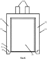
Fig. 1 is a schematic view of the electrode assembly package structure according to an embodiment of the present application; -
Figs. 2 and3 is a schematic view showing an intermediate stage of forming the structure ofFig. 1 according to an embodiment of the present application; -
Figs. 4A to 4C is schematic view of an alternative embodiment of the present application; and -
Fig. 5 is a partial enlarged view of the electrode assembly package structure according to an embodiment of the present application. - The present application will now be described with reference to the accompanying drawings. It is to be understood that the various embodiments shown in the following figures and the examples described below are exemplary embodiments of the present application and are not intended to limit the present invention. Various embodiments may be combined with one another to form other examples not shown in the figures.
- According to an embodiment of the present application, as shown in
Fig. 1 , the present application provides an electrodeassembly package structure 10. Generally, the electrodeassembly package structure 10 includes apackage side 12 and asealing side 14 extending along the length direction L of the electrodeassembly package structure 10. - Specifically, with reference to the embodiment shown in
Fig. 1 , the sealingside 14 includes afirst sealing segment 16 and asecond sealing segment 18. Among them, thefirst sealing segment 16 abuts thepackage side 12, and thesecond sealing segment 18 is located between thepackage side 12 and thefirst sealing segment 16. - In an embodiment of the present application, the
second sealing segment 18 may be formed by folding a portion of the sealingside 14 extending beyond an end of the electrodeassembly package structure 10 along the length direction L. - Specifically, the operation as described above will be described with reference to
Figs. 2 and3 . As shown inFig. 2 , thesecond sealing segment 18 may be a portion of thefirst sealing segment 16 that extends beyond the end (e.g., the bottom end) of the electrodeassembly package structure 10 that is created during electrode assembly package. Then, thesecond sealing segment 18 is folded along the length direction L so as to be stacked on thefirst sealing segment 16, as shown inFig. 3 . Further, thefirst sealing segment 16 stacked with thesecond sealing segment 18 is folded in the width direction W of thepackage structure 10 to be attached to thepackage side 12, and thesecond sealing segment 18 is sandwiched between thefirst sealing segments 16 and thepackage side 12. - In the embodiment shown in
Fig. 2 , the sealingside 14 may be folded along the fold line A to form thesecond sealing segment 18. Among them, the fold line A is perpendicular to theouter edge 15 of the sealingside 14. That is to say, in the embodiment shown inFig. 2 , the fold line A is a horizontal line; the fold line may also include other various alternative embodiments, which will be described in detail below. - By the way as described above, the
second sealing segment 18 in thesealing side 14 extending along the length direction L of the electrode assembly package structure 10 (i.e., sealing side extension portion of the sealing side 14) is sandwiched between thepackage side 12 and thefirst sealing segment 16, so that the extension portion does not occupy the length of thepackage structure 10, thereby reducing the influence of thesealing side 14 on the length of thepackage structure 10 and increasing the space utilization in the length direction. Moreover, this structure has a significant effect on the drop of the electrode assembly, and can also avoid the influence of the package on the extrusion deformation of the anode, and improve the package optimization rate. - With continued reference to
Fig. 1 , in an embodiment of the present application, theelectrode assembly 28 includes anelectrode tab 100, and thefirst sealing segment 16 of thesealing side 14 includes atop edge 20 and abottom edge 22 that are at opposite ends of theelectrode assembly 28 along the length direction L. As shown, thebottom edge 22 is away from theelectrode tab 100; correspondingly, theelectrode tab 100 is arranged on thetop edge 20 and thesecond sealing segment 18 is formed on thebottom edge 22. That is, when the package is completed, theelectrode tab 100 on the top of theelectrode assembly 28 may be exposed by the top of thepackage structure 10, and thesecond sealing segment 18 in the present application is located at the bottom of thesealing side 14, i.e., a portion away from theelectrode tab 100. That is, thetop edge 20 of thefirst sealing segment 16 is closer to theelectrode tab 100 of theelectrode assembly 28 than thebottom edge 22. - In an alternative embodiment of the present application, the outer surface of the sealing
side 14 may be affixed with an adhesive tape or coated with glue to insulate the sealingside 14. - In an alternative embodiment of the present application, the electrode
assembly package structure 10 of the present application may further include a body portion formed with an electrode assembly accommodating groove, and the body portion may include a first body portion and a second body portion that are stacked on each other. Among them, theelectrode assembly 28 to be packaged may be accommodated in the electrode assembly accommodating groove, and then the first body portion and the second body portion are folded into each other to form an integral package structure for packaging the electrode assembly. - Alternatively, for the main body portion, it may adopt a "single-pit" or "double-pit" structure. For example, for a single-pit structure, the electrode assembly accommodating groove accommodating the electrode assembly may be completely formed on the first body portion, in which case the thickness of the electrode assembly accommodating groove is equal to the thickness of the electrode assembly to be packaged. For the double-pit structure, the electrode assembly accommodating groove may include a first portion and a second portion respectively formed on the first body portion and the second body portion, and when the first portion and the second portion are folded over, the electrode assembly may be packaged therebetween. That is, the sum of the thicknesses of the first portion and the second portion at this time is equal to the thickness of the electrode assembly to be packaged. It should be understood that the structures of the main body portions of the respective embodiments as described above may be applied to the present application and may be determined according to specific use cases, and the present application is not limited thereto.
- Alternative embodiments of the present application are described below with reference to
Figs. 4A-4C . As shown inFig. 4A , in an alternative embodiment, the sealingside 14 may be folded along the fold line A1 to form thesecond sealing segment 18, and each segment of the fold line A1 is in a straight line. In other words, in the embodiment shown inFig. 4A , the fold line A1 is a continuous straight line. - Unlike the embodiment shown in
Fig. 4A , the fold lines in the form of two bent lines are shown in the embodiments shown inFigs. 4B and4C . In the embodiment shown inFig. 4B , the fold line A2 is a bent line and includes two portions that are at an angle to each other; and in the embodiment shown inFig. 4C , the fold line A3 is also a fold line, but includes three consecutive portions. It should be understood that each embodiment shown inFigs. 4A to 4C may be applied to thepackage structure 10 of the present application and may be determined according to specific use cases, and the present application is not limited thereto. - In combination with the embodiments described above, during the actual operation of the present application, the portion of the sealing
side 14 extending beyond thepackage structure 10 may be pre-cut (e.g., cut to various shapes as shown inFigs. 4A-4C ), so that the sealing segments may be eliminated more completely and the insulation treatment for the sealingside 14 is facilitated (i.e., there is no excess fold area at the bottom of thepackage structure 10 at this time). It should be understood, of course, that the above description is merely an alternative embodiment of the present application and does not constitute any limitation to the present application. - In addition, in alternative embodiments of the present application, in the length direction L of the electrode
assembly package structure 10, the length of thesecond sealing segment 18 beyond the body of theelectrode assembly 28 is less than or equal to 0.3 mm. Moreover, in the thickness direction T of the electrodeassembly package structure 10, the height of thesecond sealing segment 18 is less than or equal to the thickness of the electrodeassembly package structure 10. In other words, the formedsecond sealing segment 18 should not extend beyond the electrodeassembly package structure 10 in the thickness direction of the electrodeassembly package structure 10. - With continued reference to the drawings, in the embodiment shown in
Fig. 5 , the electrodeassembly package structure 10 may further include atop seal 24 extending in the width direction W of the electrodeassembly package structure 10, and abeveled edge 26 joined to thetop seal 24 and the sealingside 14. Similar to thesecond sealing segment 18 above, the beveled edge is also located between thefirst sealing segment 16 and thepackage side 12. Thus, the above arrangement may also not allow thebeveled edge 26 forming the extension portion of thepackage structure 10 to occupy the length of thepackage structure 10 at the top of the electrodeassembly package structure 10, thereby reducing the effect of the sealingside 14 on the length of thepackage structure 10 and increasing the space utilization in the length direction. - The foregoing is merely illustrative of the preferred embodiments of the present application and is not intended to be limiting of the present application, and various changes and modifications may be made by those skilled in the art. Any modifications, equivalent substitutions, improvements, and the like within the spirit and principles of the application are intended to be included within the scope of the present application.
Claims (10)
- An electrode assembly package structure, comprising a package side and a sealing side extending along a length of the electrode assembly package structure,
wherein the sealing side comprises a first sealing segment that abuts the package side and a second sealing segment that is between the package side and the first sealing segment. - The electrode assembly package structure according to claim 1, wherein the second sealing segment is formed by folding a portion of the sealing side extending beyond an end of the electrode assembly package structure along the length direction.
- The electrode assembly package structure according to claim 2, wherein the electrode assembly includes an electrode tab, and the first sealing segment includes a top edge and a bottom edge at both ends of the electrode assembly along the length direction, and the bottom edge is away from the electrode tab, wherein the second sealing segment is formed at the bottom edge.
- The electrode assembly package structure according to claim 1, wherein an outer surface of the sealing side is affixed with an adhesive tape or coated with glue.
- The electrode assembly package structure according to claim 2, wherein the sealing side is folded along a fold line to form the second sealing segment, and each segment of the fold line is in a straight line.
- The electrode assembly package structure according to claim 5, wherein the fold line is a bent line.
- The electrode assembly package structure according to claim 5, wherein the fold line is perpendicular to an outer edge of the sealing side.
- The electrode assembly package structure according to claim 2, wherein in the length direction of the electrode assembly package structure, the length of the second sealing segment beyond the electrode assembly is less than or equal to 0.3 mm.
- The electrode assembly package structure according to claim 1, wherein in a thickness direction of the electrode assembly package structure, a height of the second sealing segment is less than or equal to the thickness of the electrode assembly package structure.
- The electrode assembly package structure according to claim 1, further comprising a top seal extending along a width direction of the electrode assembly package structure and a beveled edge joined to the top seal and the sealing side, the beveled edge is located between the first sealing segment and the package side.
Applications Claiming Priority (1)
| Application Number | Priority Date | Filing Date | Title |
|---|---|---|---|
| PCT/CN2018/079862 WO2019178773A1 (en) | 2018-03-21 | 2018-03-21 | Cell packaging structure |
Publications (3)
| Publication Number | Publication Date |
|---|---|
| EP3624208A1 true EP3624208A1 (en) | 2020-03-18 |
| EP3624208A4 EP3624208A4 (en) | 2021-02-17 |
| EP3624208B1 EP3624208B1 (en) | 2023-02-08 |
Family
ID=67985648
Family Applications (1)
| Application Number | Title | Priority Date | Filing Date |
|---|---|---|---|
| EP18910872.3A Active EP3624208B1 (en) | 2018-03-21 | 2018-03-21 | Cell packaging structure |
Country Status (6)
| Country | Link |
|---|---|
| US (1) | US11462787B2 (en) |
| EP (1) | EP3624208B1 (en) |
| JP (1) | JP7035174B2 (en) |
| KR (1) | KR102442742B1 (en) |
| CN (1) | CN111837253B (en) |
| WO (1) | WO2019178773A1 (en) |
Cited By (2)
| Publication number | Priority date | Publication date | Assignee | Title |
|---|---|---|---|---|
| EP4131597A4 (en) * | 2020-03-31 | 2024-07-31 | Ningde Amperex Technology Ltd. | PACKAGING STRUCTURE AND ELECTROCHEMICAL DEVICE APPLYING PACKAGING STRUCTURE |
| EP4500628A4 (en) * | 2022-03-31 | 2026-04-01 | Enovix Corp | METHOD FOR PRODUCING A SECONDARY BATTERY ASSEMBLY |
Families Citing this family (7)
| Publication number | Priority date | Publication date | Assignee | Title |
|---|---|---|---|---|
| WO2018117654A1 (en) * | 2016-12-20 | 2018-06-28 | 에스케이이노베이션 주식회사 | Pouch-type secondary battery and manufacturing method therefor |
| KR102928371B1 (en) * | 2020-02-07 | 2026-02-19 | 주식회사 엘지에너지솔루션 | Pouch type secondary battery and battery module |
| US20230046849A1 (en) * | 2020-02-07 | 2023-02-16 | Lg Energy Solution, Ltd. | Pouch-Type Secondary Battery and Battery Module |
| KR102883169B1 (en) * | 2020-07-30 | 2025-11-06 | 에스케이온 주식회사 | Pouch for secondary battery, secondary battery and method of manufacturing the same |
| CN114284539B (en) * | 2020-09-18 | 2024-06-11 | 宁德新能源科技有限公司 | Battery |
| CN113241466B (en) * | 2021-05-11 | 2022-07-26 | 宜春清陶能源科技有限公司 | Packaging process of battery |
| KR102926140B1 (en) * | 2021-09-03 | 2026-02-12 | 에스케이온 주식회사 | Battery cell and battery module including same |
Family Cites Families (21)
| Publication number | Priority date | Publication date | Assignee | Title |
|---|---|---|---|---|
| JP3825593B2 (en) | 1999-10-15 | 2006-09-27 | Tdk株式会社 | Manufacturing method of package |
| US6482544B1 (en) * | 2000-06-30 | 2002-11-19 | Mitsubishi Denki Kabushiki Kaisha | Battery package |
| JP2002260602A (en) | 2001-02-28 | 2002-09-13 | Sanyo Electric Co Ltd | Thin battery |
| JP2002319375A (en) | 2001-04-19 | 2002-10-31 | Yuasa Corp | Sealed battery |
| KR100858798B1 (en) * | 2002-06-17 | 2008-09-17 | 삼성에스디아이 주식회사 | Battery and its manufacturing method |
| JP4206735B2 (en) * | 2002-11-26 | 2009-01-14 | パナソニック電工株式会社 | Electric toothbrush |
| KR100922742B1 (en) * | 2002-12-17 | 2009-10-22 | 삼성에스디아이 주식회사 | Pouch type case and lithium secondary battery using same |
| KR100553753B1 (en) | 2003-10-16 | 2006-02-20 | 삼성에스디아이 주식회사 | Pouch Type Secondary Battery |
| JP4819512B2 (en) * | 2006-01-24 | 2011-11-24 | Necエナジーデバイス株式会社 | Laminated battery |
| CN202134580U (en) * | 2011-04-14 | 2012-02-01 | 东莞新能源科技有限公司 | A kind of lithium ion battery and packaging foil thereof |
| CN202434586U (en) * | 2011-12-28 | 2012-09-12 | 天津力神电池股份有限公司 | Encapsulation structure for flexible battery |
| KR101905077B1 (en) * | 2012-01-19 | 2018-10-05 | 삼성에스디아이 주식회사 | Reinforcing material for battery cell and battery cell using the same |
| CN203800091U (en) * | 2014-03-21 | 2014-08-27 | 东莞新能源科技有限公司 | Soft-package battery |
| KR102211525B1 (en) * | 2014-06-17 | 2021-02-02 | 삼성에스디아이 주식회사 | Rechargeable battery having coner folding part |
| US20160093837A1 (en) | 2014-09-30 | 2016-03-31 | Apple Inc. | Efficient Battery Pouch |
| KR101927262B1 (en) * | 2015-11-03 | 2018-12-10 | 주식회사 엘지화학 | A pouch case for a secondary battery |
| CN105514307A (en) * | 2016-01-22 | 2016-04-20 | 宁德新能源科技有限公司 | Lithium-ion battery packaging housing and lithium ion battery comprising same |
| CN206422169U (en) * | 2016-11-18 | 2017-08-18 | 宁德新能源科技有限公司 | Battery core encapsulating structure |
| CN206250224U (en) * | 2016-11-18 | 2017-06-13 | 宁德新能源科技有限公司 | Battery core encapsulating structure |
| KR102263470B1 (en) * | 2017-04-12 | 2021-06-11 | 주식회사 엘지에너지솔루션 | Battery Cell Comprising Hot-melting Adhesive Part |
| KR102109926B1 (en) * | 2017-07-20 | 2020-05-12 | 주식회사 엘지화학 | Pouch case for secondary battery, pouch type secondary battery and manufacturing method thereof using the same |
-
2018
- 2018-03-21 KR KR1020207008568A patent/KR102442742B1/en active Active
- 2018-03-21 EP EP18910872.3A patent/EP3624208B1/en active Active
- 2018-03-21 WO PCT/CN2018/079862 patent/WO2019178773A1/en not_active Ceased
- 2018-03-21 CN CN201880054106.6A patent/CN111837253B/en active Active
- 2018-03-21 JP JP2020517333A patent/JP7035174B2/en active Active
- 2018-09-18 US US16/133,925 patent/US11462787B2/en active Active
Cited By (2)
| Publication number | Priority date | Publication date | Assignee | Title |
|---|---|---|---|---|
| EP4131597A4 (en) * | 2020-03-31 | 2024-07-31 | Ningde Amperex Technology Ltd. | PACKAGING STRUCTURE AND ELECTROCHEMICAL DEVICE APPLYING PACKAGING STRUCTURE |
| EP4500628A4 (en) * | 2022-03-31 | 2026-04-01 | Enovix Corp | METHOD FOR PRODUCING A SECONDARY BATTERY ASSEMBLY |
Also Published As
| Publication number | Publication date |
|---|---|
| CN111837253A (en) | 2020-10-27 |
| KR20200045525A (en) | 2020-05-04 |
| JP2020535605A (en) | 2020-12-03 |
| EP3624208B1 (en) | 2023-02-08 |
| US11462787B2 (en) | 2022-10-04 |
| CN111837253B (en) | 2022-06-17 |
| US20190296271A1 (en) | 2019-09-26 |
| WO2019178773A1 (en) | 2019-09-26 |
| JP7035174B2 (en) | 2022-03-14 |
| KR102442742B1 (en) | 2022-09-13 |
| EP3624208A4 (en) | 2021-02-17 |
Similar Documents
| Publication | Publication Date | Title |
|---|---|---|
| US11462787B2 (en) | Electrode assembly package structure | |
| US20260121255A1 (en) | Secondary battery | |
| US11108089B2 (en) | Cell, battery and electronic device | |
| CN111403789B (en) | Electrode assembly and battery | |
| CN210092210U (en) | Battery | |
| US11362363B2 (en) | Battery | |
| CN209785987U (en) | Secondary battery | |
| WO2022222941A1 (en) | Battery | |
| CN209592206U (en) | Secondary cell | |
| CN112086585B (en) | Battery | |
| US10833371B2 (en) | Wound-type cell | |
| CN211350808U (en) | Electrochemical devices and electronic devices | |
| CN205846128U (en) | A secondary battery cell | |
| JP2007200589A (en) | Laminate battery | |
| KR20230085534A (en) | Battery Cell with Chamfered Protective Tape | |
| CN216488201U (en) | Battery with a battery cell | |
| US11456445B2 (en) | Electrode, method for manufacturing the same, electrode assembly, and secondary battery | |
| CN107302110A (en) | Takeup type battery core | |
| JP2006313655A (en) | Thin battery | |
| CN219832822U (en) | Battery cell and battery module | |
| EP3641017B1 (en) | Rechargeable battery | |
| CN205376619U (en) | Thin battery | |
| CN223797413U (en) | Battery cell and battery pack | |
| JP7861345B2 (en) | Battery cell with beveled protective tape | |
| CN219476769U (en) | An electrode assembly and a wound lithium ion battery |
Legal Events
| Date | Code | Title | Description |
|---|---|---|---|
| STAA | Information on the status of an ep patent application or granted ep patent |
Free format text: STATUS: THE INTERNATIONAL PUBLICATION HAS BEEN MADE |
|
| PUAI | Public reference made under article 153(3) epc to a published international application that has entered the european phase |
Free format text: ORIGINAL CODE: 0009012 |
|
| STAA | Information on the status of an ep patent application or granted ep patent |
Free format text: STATUS: REQUEST FOR EXAMINATION WAS MADE |
|
| 17P | Request for examination filed |
Effective date: 20191212 |
|
| AK | Designated contracting states |
Kind code of ref document: A1 Designated state(s): AL AT BE BG CH CY CZ DE DK EE ES FI FR GB GR HR HU IE IS IT LI LT LU LV MC MK MT NL NO PL PT RO RS SE SI SK SM TR |
|
| AX | Request for extension of the european patent |
Extension state: BA ME |
|
| REG | Reference to a national code |
Ref country code: DE Ref legal event code: R079 Ref document number: 602018046068 Country of ref document: DE Free format text: PREVIOUS MAIN CLASS: H01M0002020000 Ipc: H01M0050100000 |
|
| A4 | Supplementary search report drawn up and despatched |
Effective date: 20210118 |
|
| RIC1 | Information provided on ipc code assigned before grant |
Ipc: H01M 50/10 20210101AFI20210204BHEP |
|
| DAV | Request for validation of the european patent (deleted) | ||
| DAX | Request for extension of the european patent (deleted) | ||
| GRAP | Despatch of communication of intention to grant a patent |
Free format text: ORIGINAL CODE: EPIDOSNIGR1 |
|
| STAA | Information on the status of an ep patent application or granted ep patent |
Free format text: STATUS: GRANT OF PATENT IS INTENDED |
|
| INTG | Intention to grant announced |
Effective date: 20220902 |
|
| GRAS | Grant fee paid |
Free format text: ORIGINAL CODE: EPIDOSNIGR3 |
|
| GRAA | (expected) grant |
Free format text: ORIGINAL CODE: 0009210 |
|
| STAA | Information on the status of an ep patent application or granted ep patent |
Free format text: STATUS: THE PATENT HAS BEEN GRANTED |
|
| AK | Designated contracting states |
Kind code of ref document: B1 Designated state(s): AL AT BE BG CH CY CZ DE DK EE ES FI FR GB GR HR HU IE IS IT LI LT LU LV MC MK MT NL NO PL PT RO RS SE SI SK SM TR |
|
| REG | Reference to a national code |
Ref country code: GB Ref legal event code: FG4D |
|
| REG | Reference to a national code |
Ref country code: CH Ref legal event code: EP Ref country code: AT Ref legal event code: REF Ref document number: 1547667 Country of ref document: AT Kind code of ref document: T Effective date: 20230215 |
|
| REG | Reference to a national code |
Ref country code: IE Ref legal event code: FG4D |
|
| REG | Reference to a national code |
Ref country code: DE Ref legal event code: R096 Ref document number: 602018046068 Country of ref document: DE |
|
| REG | Reference to a national code |
Ref country code: NL Ref legal event code: FP |
|
| REG | Reference to a national code |
Ref country code: LT Ref legal event code: MG9D |
|
| P01 | Opt-out of the competence of the unified patent court (upc) registered |
Effective date: 20230601 |
|
| REG | Reference to a national code |
Ref country code: AT Ref legal event code: MK05 Ref document number: 1547667 Country of ref document: AT Kind code of ref document: T Effective date: 20230208 |
|
| PG25 | Lapsed in a contracting state [announced via postgrant information from national office to epo] |
Ref country code: RS Free format text: LAPSE BECAUSE OF FAILURE TO SUBMIT A TRANSLATION OF THE DESCRIPTION OR TO PAY THE FEE WITHIN THE PRESCRIBED TIME-LIMIT Effective date: 20230208 Ref country code: PT Free format text: LAPSE BECAUSE OF FAILURE TO SUBMIT A TRANSLATION OF THE DESCRIPTION OR TO PAY THE FEE WITHIN THE PRESCRIBED TIME-LIMIT Effective date: 20230609 Ref country code: NO Free format text: LAPSE BECAUSE OF FAILURE TO SUBMIT A TRANSLATION OF THE DESCRIPTION OR TO PAY THE FEE WITHIN THE PRESCRIBED TIME-LIMIT Effective date: 20230508 Ref country code: LV Free format text: LAPSE BECAUSE OF FAILURE TO SUBMIT A TRANSLATION OF THE DESCRIPTION OR TO PAY THE FEE WITHIN THE PRESCRIBED TIME-LIMIT Effective date: 20230208 Ref country code: LT Free format text: LAPSE BECAUSE OF FAILURE TO SUBMIT A TRANSLATION OF THE DESCRIPTION OR TO PAY THE FEE WITHIN THE PRESCRIBED TIME-LIMIT Effective date: 20230208 Ref country code: HR Free format text: LAPSE BECAUSE OF FAILURE TO SUBMIT A TRANSLATION OF THE DESCRIPTION OR TO PAY THE FEE WITHIN THE PRESCRIBED TIME-LIMIT Effective date: 20230208 Ref country code: ES Free format text: LAPSE BECAUSE OF FAILURE TO SUBMIT A TRANSLATION OF THE DESCRIPTION OR TO PAY THE FEE WITHIN THE PRESCRIBED TIME-LIMIT Effective date: 20230208 Ref country code: AT Free format text: LAPSE BECAUSE OF FAILURE TO SUBMIT A TRANSLATION OF THE DESCRIPTION OR TO PAY THE FEE WITHIN THE PRESCRIBED TIME-LIMIT Effective date: 20230208 |
|
| PG25 | Lapsed in a contracting state [announced via postgrant information from national office to epo] |
Ref country code: SE Free format text: LAPSE BECAUSE OF FAILURE TO SUBMIT A TRANSLATION OF THE DESCRIPTION OR TO PAY THE FEE WITHIN THE PRESCRIBED TIME-LIMIT Effective date: 20230208 Ref country code: PL Free format text: LAPSE BECAUSE OF FAILURE TO SUBMIT A TRANSLATION OF THE DESCRIPTION OR TO PAY THE FEE WITHIN THE PRESCRIBED TIME-LIMIT Effective date: 20230208 Ref country code: IS Free format text: LAPSE BECAUSE OF FAILURE TO SUBMIT A TRANSLATION OF THE DESCRIPTION OR TO PAY THE FEE WITHIN THE PRESCRIBED TIME-LIMIT Effective date: 20230608 Ref country code: GR Free format text: LAPSE BECAUSE OF FAILURE TO SUBMIT A TRANSLATION OF THE DESCRIPTION OR TO PAY THE FEE WITHIN THE PRESCRIBED TIME-LIMIT Effective date: 20230509 Ref country code: FI Free format text: LAPSE BECAUSE OF FAILURE TO SUBMIT A TRANSLATION OF THE DESCRIPTION OR TO PAY THE FEE WITHIN THE PRESCRIBED TIME-LIMIT Effective date: 20230208 |
|
| PG25 | Lapsed in a contracting state [announced via postgrant information from national office to epo] |
Ref country code: SM Free format text: LAPSE BECAUSE OF FAILURE TO SUBMIT A TRANSLATION OF THE DESCRIPTION OR TO PAY THE FEE WITHIN THE PRESCRIBED TIME-LIMIT Effective date: 20230208 Ref country code: RO Free format text: LAPSE BECAUSE OF FAILURE TO SUBMIT A TRANSLATION OF THE DESCRIPTION OR TO PAY THE FEE WITHIN THE PRESCRIBED TIME-LIMIT Effective date: 20230208 Ref country code: EE Free format text: LAPSE BECAUSE OF FAILURE TO SUBMIT A TRANSLATION OF THE DESCRIPTION OR TO PAY THE FEE WITHIN THE PRESCRIBED TIME-LIMIT Effective date: 20230208 Ref country code: DK Free format text: LAPSE BECAUSE OF FAILURE TO SUBMIT A TRANSLATION OF THE DESCRIPTION OR TO PAY THE FEE WITHIN THE PRESCRIBED TIME-LIMIT Effective date: 20230208 Ref country code: CZ Free format text: LAPSE BECAUSE OF FAILURE TO SUBMIT A TRANSLATION OF THE DESCRIPTION OR TO PAY THE FEE WITHIN THE PRESCRIBED TIME-LIMIT Effective date: 20230208 |
|
| REG | Reference to a national code |
Ref country code: CH Ref legal event code: PL |
|
| REG | Reference to a national code |
Ref country code: DE Ref legal event code: R097 Ref document number: 602018046068 Country of ref document: DE |
|
| PG25 | Lapsed in a contracting state [announced via postgrant information from national office to epo] |
Ref country code: SK Free format text: LAPSE BECAUSE OF FAILURE TO SUBMIT A TRANSLATION OF THE DESCRIPTION OR TO PAY THE FEE WITHIN THE PRESCRIBED TIME-LIMIT Effective date: 20230208 |
|
| REG | Reference to a national code |
Ref country code: BE Ref legal event code: MM Effective date: 20230331 |
|
| PLBE | No opposition filed within time limit |
Free format text: ORIGINAL CODE: 0009261 |
|
| STAA | Information on the status of an ep patent application or granted ep patent |
Free format text: STATUS: NO OPPOSITION FILED WITHIN TIME LIMIT |
|
| PG25 | Lapsed in a contracting state [announced via postgrant information from national office to epo] |
Ref country code: LU Free format text: LAPSE BECAUSE OF NON-PAYMENT OF DUE FEES Effective date: 20230321 |
|
| 26N | No opposition filed |
Effective date: 20231109 |
|
| PG25 | Lapsed in a contracting state [announced via postgrant information from national office to epo] |
Ref country code: MC Free format text: LAPSE BECAUSE OF FAILURE TO SUBMIT A TRANSLATION OF THE DESCRIPTION OR TO PAY THE FEE WITHIN THE PRESCRIBED TIME-LIMIT Effective date: 20230208 |
|
| REG | Reference to a national code |
Ref country code: IE Ref legal event code: MM4A |
|
| PG25 | Lapsed in a contracting state [announced via postgrant information from national office to epo] |
Ref country code: SI Free format text: LAPSE BECAUSE OF FAILURE TO SUBMIT A TRANSLATION OF THE DESCRIPTION OR TO PAY THE FEE WITHIN THE PRESCRIBED TIME-LIMIT Effective date: 20230208 Ref country code: MC Free format text: LAPSE BECAUSE OF FAILURE TO SUBMIT A TRANSLATION OF THE DESCRIPTION OR TO PAY THE FEE WITHIN THE PRESCRIBED TIME-LIMIT Effective date: 20230208 Ref country code: LI Free format text: LAPSE BECAUSE OF NON-PAYMENT OF DUE FEES Effective date: 20230331 Ref country code: IE Free format text: LAPSE BECAUSE OF NON-PAYMENT OF DUE FEES Effective date: 20230321 Ref country code: CH Free format text: LAPSE BECAUSE OF NON-PAYMENT OF DUE FEES Effective date: 20230331 |
|
| PG25 | Lapsed in a contracting state [announced via postgrant information from national office to epo] |
Ref country code: BE Free format text: LAPSE BECAUSE OF NON-PAYMENT OF DUE FEES Effective date: 20230331 |
|
| PG25 | Lapsed in a contracting state [announced via postgrant information from national office to epo] |
Ref country code: IT Free format text: LAPSE BECAUSE OF FAILURE TO SUBMIT A TRANSLATION OF THE DESCRIPTION OR TO PAY THE FEE WITHIN THE PRESCRIBED TIME-LIMIT Effective date: 20230208 |
|
| PG25 | Lapsed in a contracting state [announced via postgrant information from national office to epo] |
Ref country code: BG Free format text: LAPSE BECAUSE OF FAILURE TO SUBMIT A TRANSLATION OF THE DESCRIPTION OR TO PAY THE FEE WITHIN THE PRESCRIBED TIME-LIMIT Effective date: 20230208 |
|
| PG25 | Lapsed in a contracting state [announced via postgrant information from national office to epo] |
Ref country code: BG Free format text: LAPSE BECAUSE OF FAILURE TO SUBMIT A TRANSLATION OF THE DESCRIPTION OR TO PAY THE FEE WITHIN THE PRESCRIBED TIME-LIMIT Effective date: 20230208 |
|
| PG25 | Lapsed in a contracting state [announced via postgrant information from national office to epo] |
Ref country code: CY Free format text: LAPSE BECAUSE OF FAILURE TO SUBMIT A TRANSLATION OF THE DESCRIPTION OR TO PAY THE FEE WITHIN THE PRESCRIBED TIME-LIMIT; INVALID AB INITIO Effective date: 20180321 |
|
| PG25 | Lapsed in a contracting state [announced via postgrant information from national office to epo] |
Ref country code: HU Free format text: LAPSE BECAUSE OF FAILURE TO SUBMIT A TRANSLATION OF THE DESCRIPTION OR TO PAY THE FEE WITHIN THE PRESCRIBED TIME-LIMIT; INVALID AB INITIO Effective date: 20180321 |
|
| PG25 | Lapsed in a contracting state [announced via postgrant information from national office to epo] |
Ref country code: TR Free format text: LAPSE BECAUSE OF FAILURE TO SUBMIT A TRANSLATION OF THE DESCRIPTION OR TO PAY THE FEE WITHIN THE PRESCRIBED TIME-LIMIT Effective date: 20230208 |
|
| PGFP | Annual fee paid to national office [announced via postgrant information from national office to epo] |
Ref country code: NL Payment date: 20260213 Year of fee payment: 9 |
|
| PGFP | Annual fee paid to national office [announced via postgrant information from national office to epo] |
Ref country code: GB Payment date: 20260202 Year of fee payment: 9 |
|
| PGFP | Annual fee paid to national office [announced via postgrant information from national office to epo] |
Ref country code: DE Payment date: 20260204 Year of fee payment: 9 |
|
| PGFP | Annual fee paid to national office [announced via postgrant information from national office to epo] |
Ref country code: FR Payment date: 20260209 Year of fee payment: 9 |