EP3623989A1 - Liquid level detecting method and device using the same - Google Patents
Liquid level detecting method and device using the same Download PDFInfo
- Publication number
- EP3623989A1 EP3623989A1 EP19151932.1A EP19151932A EP3623989A1 EP 3623989 A1 EP3623989 A1 EP 3623989A1 EP 19151932 A EP19151932 A EP 19151932A EP 3623989 A1 EP3623989 A1 EP 3623989A1
- Authority
- EP
- European Patent Office
- Prior art keywords
- image
- mark
- liquid level
- marking component
- width
- Prior art date
- Legal status (The legal status is an assumption and is not a legal conclusion. Google has not performed a legal analysis and makes no representation as to the accuracy of the status listed.)
- Withdrawn
Links
Images




Classifications
-
- G—PHYSICS
- G06—COMPUTING OR CALCULATING; COUNTING
- G06T—IMAGE DATA PROCESSING OR GENERATION, IN GENERAL
- G06T7/00—Image analysis
- G06T7/70—Determining position or orientation of objects or cameras
- G06T7/73—Determining position or orientation of objects or cameras using feature-based methods
- G06T7/74—Determining position or orientation of objects or cameras using feature-based methods involving reference images or patches
-
- G—PHYSICS
- G01—MEASURING; TESTING
- G01F—MEASURING VOLUME, VOLUME FLOW, MASS FLOW OR LIQUID LEVEL; METERING BY VOLUME
- G01F23/00—Indicating or measuring liquid level or level of fluent solid material, e.g. indicating in terms of volume or indicating by means of an alarm
- G01F23/04—Indicating or measuring liquid level or level of fluent solid material, e.g. indicating in terms of volume or indicating by means of an alarm by dip members, e.g. dip-sticks
-
- G—PHYSICS
- G06—COMPUTING OR CALCULATING; COUNTING
- G06T—IMAGE DATA PROCESSING OR GENERATION, IN GENERAL
- G06T7/00—Image analysis
- G06T7/60—Analysis of geometric attributes
- G06T7/62—Analysis of geometric attributes of area, perimeter, diameter or volume
-
- H—ELECTRICITY
- H04—ELECTRIC COMMUNICATION TECHNIQUE
- H04N—PICTORIAL COMMUNICATION, e.g. TELEVISION
- H04N5/00—Details of television systems
- H04N5/14—Picture signal circuitry for video frequency region
-
- G—PHYSICS
- G06—COMPUTING OR CALCULATING; COUNTING
- G06T—IMAGE DATA PROCESSING OR GENERATION, IN GENERAL
- G06T2207/00—Indexing scheme for image analysis or image enhancement
- G06T2207/30—Subject of image; Context of image processing
- G06T2207/30204—Marker
-
- G—PHYSICS
- G06—COMPUTING OR CALCULATING; COUNTING
- G06V—IMAGE OR VIDEO RECOGNITION OR UNDERSTANDING
- G06V2201/00—Indexing scheme relating to image or video recognition or understanding
- G06V2201/06—Recognition of objects for industrial automation
Definitions
- the invention relates in general to a liquid level detecting method and a liquid level detecting device using the same.
- the external ventricular drainage system includes a container and a pressure valve connecting the container to a brain chamber.
- the pressure valve When the brain pressure inside the brain chamber is too large, the pressure valve will be opened, such that the liquid inside the brain chamber can be drained to the container.
- Different medical orders are provided in response to the change in the liquid level (the brain fluid volume) of the brain fluid inside the container.
- the medical staff need to be on site to physically observe the change in the liquid level of the brain fluid inside the container and determine what corresponding medical order needs to be taken.
- a liquid level detecting method includes the following steps. Firstly, a transmissive container image of a transmissive container and a marking component image of a marking component are captured by a camera from a front surface of the transmissive container, wherein the transmissive container is configured for containing a liquid, and the marking component is located on a rear surface of the transmissive container. Then, the marker component image is analyzed downward from an end portion of the marker element image to obtain a plurality of width values of a plurality of position points of the marker component image. Then, a width difference between each width value and a width average of the marking component image is obtained. Then, a position point whose width difference value is not within a preset range is determined as the liquid level of the liquid.
- a liquid level detecting device configured for detecting a liquid level of a liquid contained in a transmissive container.
- a marking component is located on a rear surface of the transmissive container.
- the liquid level detecting device includes a camera, an image analyzer and a liquid level determiner. The camera is configured for capturing a transmissive container image of the transmissive container and a marking component image of the marking component from a front surface of the transmissive container.
- the image analyzer is configured for analyzing the marking component image downward from an end portion of the marking component image to obtain a plurality of width values of a plurality of position points of the marker component image and obtaining a width difference between each width value and a width average of the marking component image.
- the liquid level determiner is configured for determining a position point whose width difference is not within a preset range as the liquid level of the liquid.
- FIG. 1 is a flowchart of obtaining a width average W av of a marking component image M12 according to an embodiment of the present disclosure.
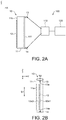
- FIG. 2A is a schematic diagram of a liquid level detecting device 100 according to an embodiment of the present disclosure.
- FIG. 2B is a schematic diagram of a transmissive container viewed from a front surface 11f of the transmissive container of FIG. 2A .
- FIG. 2C is a schematic diagram of a receiving component image M1 captured by the camera of FIG. 2A from a front surface 11f of a transmissive container 11.
- FIG. 2D is a schematic diagram of the marking component image M12, the first mark image and the second mark image of FIG. 2C.
- FIG. 2E is a schematic diagram of a width of the marking component image M12 of FIG. 2D .
- the liquid level detecting device 100 includes a camera 110 and an image analyzer 120.
- the liquid level detecting device 100 is configured for detecting a liquid level of a liquid L1 contained in the transmissive container 11 (the liquid L1 is illustrated in FIG. 4A ).
- the liquid level detecting device 100 can be used in medical field such as the external ventricular drainage system for automatically determining the liquid level of the liquid drained to the transmissive container 11 from the brain chamber. In another embodiment, the liquid level detecting device 100 can be used outside the medical field.
- the liquid level detecting method and the liquid level detecting device using the same disclosed in the embodiments of the present disclosure can be used in any application fields in which corresponding operation is taken according to the observation of the liquid level.
- the receiving component 10 includes a transmissive container 11, in which a liquid L1 (the liquid L1 is illustrated in FIG. 4A ) is contained, and a marking component 12 located on a rear surface 11b of the transmissive container 11.
- the transmissive container 11 can be realized by a measuring cylinder, a drip-feeding bottle or any liquid container, and the liquid can be body fluid, liquid medicine, water, nutrient solution or other suitable liquid.
- the color of the marking component 12 and that of the transmissive container 11 can be differentiated from each other.
- the color of the marking component 12 can be darker than that of the transmissive container 11, and can be black, blue or other suitable color.
- the receiving component 10 further includes a first mark 13 and a second mark 14, wherein the first mark 13 and the second mark 14 are located on a front surface 11f of the transmissive container 11. Additionally, the first mark 13, the second mark 14 and the marking component 12 are separated from one another. Viewing towards the front surface 11f as indicated in FIG. 2B , the marking component 12 is located between the first mark 13 and the second mark 14; the first mark 13, the second mark 14 and the marking component 12 are separated from one another and do not overlap at all. Besides, the color of the first mark 13 and the second mark 14 can be similar or identical to that of the marking component 12, and is not repeated here. As indicated in FIG.
- the transmissive container 11 has a scale 11a.
- the scale 11a can be located on a lateral side of the transmissive container 11, such that the scale 11a is least seen (or cannot be seen) in the diagram of the transmissive container viewed from the front surface 11f (such as FIG. 2B ).
- the scale image (if any) will not affect the determination of the liquid level in subsequent step of image analysis.
- the extending direction S1 of the marking component 12 is substantially parallel to the direction of the connection line S2 connecting the first mark 13 and the second mark 14.
- the first mark 13 is a first triangle
- the second mark 14 is a second triangle
- the bottom side 13e of the first mark 13 and the bottom side 14e of the second mark 14 are opposite to each other.
- the connection line S2 connecting the first mark 13 and the second mark 14 passes through the marking component 12.
- the connection line S2 substantially overlaps a first long side 12e1 of the marking component 12.
- the connection line S2 passes through the region between the first long side 12e1 and the second long side 12e2 of the marking component 12.
- step S110 the camera 110 captures a receiving component image M1 of the receiving component 10 from the front surface 11f of the transmissive container 11; the receiving component image M1 includes a transmissive container image M11, a marking component image M12, a first mark image M13 and a second mark image M14.
- the image analyzer 120 performs a binary image processing operation on the receiving component image M1. For example, among the pixels of the receiving component image M1 of FIG. 2C , the image analyzer 120 sets the pixels of the edge image M11e of the transmissive container image M11, the pixels of the marking component image M12, the pixels of the first mark image M13 and the pixels of the second mark image M14 as the first gray level, and sets the pixels other than the edge image M11e of the transmissive container image M11, the pixels other than the marking component image M12, the pixels other than the first mark image M13 and the pixels other than the second mark image M14 as the second gray level.
- the second gray level and the first gray level are not the same. In the present embodiment as indicated in FIG.
- the first gray level is such as 0 (black, represented by a cross-section), and the second gray level is such as 255 (white, the region other than the cross-section).
- the first gray level and/or the second gray level can be any value between 0-255.
- FIG. 2D Due to the transmittance of the transmissive container 11, only the edge pixels of the transmissive container image M11 are set as the first gray level (the edge image M11e has a darker color and is more obvious), and all or most of the remaining pixels of the transmissive container image M11 are set as the second gray level.
- the pixels of the background image B1 illustrated in FIG. 2C ) are also set as the first gray level (as indicated in FIG. 2D ).
- step S120 the image analyzer 120 analyzes the marking component image M12 downward from an end portion M12a of the marking component image M12 to obtain a plurality of width values W i of a plurality of position points P i of the marking component image M12 as indicated in FIG. 2E , wherein the subscript i indicates the i-th position point.
- the value of the subscript i can be any positive integer between 1-m, wherein m represents a total number of position points P i , and can be any positive integer. As indicated in FIG.
- the first position point P 1 is such as the position of an end portion M12a
- the last position point P m is such as the position of another end portion M12b of the marking component image M12.
- the end portion M12a is a top end of the marking component image M12
- the end portion M12b is a bottom end of the marking component image M12.
- one of the many methods by which the image analyzer 120 can obtain the width value W i is disclosed below.
- the image analyzer 120 calculates the width value of each position point within a distance D1 from a starting point, being the connection line S2 connecting the first mark image M13 and the second mark image M14, towards a direction substantially perpendicular to the connection line S2 (such as in a direction towards the second long side image M12e2 of the marking component image M12 to cover the range of the marking component image M12), and calculates the width value W i of each position point P i within the range of the distance D1.
- the range of the distance D1 at least covers the second long side image M12e2 of the marking component image M12, but does not go beyond the edge image M11e of the transmissive container image M11.
- the image analyzer 120 calculates a cumulative count of the pixels having the first gray level within the range of the distance D1, and determines the width value W i according to the cumulative count of pixels. The larger the number of pixels, the larger the width value W i .
- the accumulated width image is illustrated in FIG. 2E .
- the width value W i is more accurate. Also, since the range of the distance D1 at least covers the second long side image M12e2 of the marking component image M12, the number of the pixels of the marking component image M12 will be accumulated to the cumulative count of the pixels of the marking component image M12.
- the width value W i is more accurate.
- the range of the distance D1 at least covers the second long side image M12e2 of the marking component image M12 but does not go beyond the edge image M11e of the transmissive container image M11, all or most of the accumulated pixels are the pixels of the marking component image M12 along the width. Therefore, the obtained width value W i is more accurate.
- the image analyzer 120 calculates the width value W i within the range of the distance D1 in a direction substantially perpendicular to the connection line S2, the width value W i obtained when the receiving component 10 is inclined (for example, the extending direction of the marking component 12 is not parallel to the Z-axis) is similar or identical to the width value W i obtained when the receiving component 10 is not inclined (for example, the extending direction of the marking component 12 of FIG. 2B is substantially parallel to the Z-axis).
- the image analyzer 120 calculates the width value W i within the range of the distance D1 in a direction substantially perpendicular to the connection line S2, an accurate or consistent determination result of the liquid level can be obtained without considering the relative position/angle between the image analyzer 120 and the receiving component 10.
- the Z-axis which passes the geocentric center or is perpendicular to the ground.
- the Z-axis is the vertical line.
- step S130 the image analyzer 120 calculates a plurality of width values W i according to equation (1) to obtain a width average W av .
- m represents a total number of position points, and can be any positive integer equivalent to or greater than 1.
- liquid level detecting method according to a plurality of embodiments of the present disclosure is disclosed below.
- FIG. 3 is a flowchart of a liquid level detecting method according to an embodiment of the present disclosure.
- FIG. 4A is a schematic diagram of the liquid contained in the transmissive container of FIG. 2A being at a low liquid level.
- FIG. 4B is a schematic diagram of a receiving component image M1 captured by the camera of FIG. 4A from a front surface 11f of the transmitting container.
- FIG. 4C is a schematic diagram of the marking component image M12, the first mark image M13 and the second mark image M14 of FIG. 4B .
- FIG. 4D is a schematic diagram of width change in the marking component image M12 of FIG. 4C .
- the liquid level detecting device 200 includes a camera 110, an image analyzer 120 and a liquid level determiner 230.
- the liquid level determiner 230 electrically connects the camera 110 and the image analyzer 120 for determining a position point whose width difference is not within a preset range (here below referred as "point having abrupt change in width"), and then determining a liquid level of the liquid L1 according to the point having abrupt change in width.
- the image analyzer 120 and/or the liquid level determiner 230 can be realized by circuits formed by a semiconductor process or can be integrated as a circuit.
- the image analyzer 120 and the liquid level determiner 230 can be integrated as a processor or integrated to the central processing unit (CPU).
- step S210 the camera 110 captures a receiving component image M1 of the receiving component 10 from a front surface 11f of the transmissive container 11, wherein the receiving component image M1 includes a transmissive container image M11, a marking component image M12, a first mark image M13 and a second mark image M14.
- the part of the marking component image M12 being blocked by the liquid L1 is magnified due to the refractive index of the liquid L1.
- the image analyzer 120 performs a binary image processing operation on the receiving component image M1.
- the image analyzer 120 sets the pixels of the edge image M11e of the transmissive container image M11, the pixels of the marking component image M12, the pixels of the first mark image M13 and the pixels of the second mark image M14 as the first gray level, and sets the pixels other than the edge image M11e of the transmissive container image M11, the pixels other than the marking component image M12, the pixels other than the first mark image M13 and the pixels other than the second mark image M14 as the second gray level.
- the second gray level and the first gray level are not the same. In the present embodiment as indicated in FIG.
- the first gray level is such as 0 (black, represented by a cross-section), and the second gray level is such as 255 (white, the region other than the cross-section).
- the first gray level and/or the second gray level can be any value between 0-255.
- FIG. 4C Due to the transmittance of the transmissive container 11 and the liquid L1, only the edge pixels of the transmissive container image M11 are set as the first gray level (the edge image M11e has a darker color and is more obvious), and all or most of the remaining pixels of the transmissive container image M11 are set as the second gray level.
- the pixels of the background image B1 are also set as the first gray level (as indicated in FIG. 4C )
- step S220 the image analyzer 120 analyzes the marking component image M12 downward from an end portion M12a of the marking component image M12 to obtain a plurality of width values W i of a plurality of position points P i of the marking component image M12, wherein the subscript i indicates the i-th position point.
- the first position point P i is such as the position of an end portion M12a
- the last position point P m is such as the position of another end portion M12b of the marking component image M12.
- the end portion M12a is a top end of the marking component image M12
- the end portion M12b is a bottom end of the marking component image M12.
- one of the many methods by which the image analyzer 120 can obtain the width value W i is disclosed below.
- the image analyzer 120 calculates the width value of each position point within a distance D1 from a starting point, being the connection line S2 connecting the first mark image M13 and the second mark image M14, towards a direction substantially perpendicular to the connection line S2 (such as in a direction towards the second long side image M12e2 of the marking component image M12 to cover the range of the marking component image M12), and calculates the width value W i of each position point P i within the range of the distance D1.
- the image analyzer 120 calculates a cumulative count of the pixels having the first gray level within the range of the distance D1, and determines the width value W i according to the cumulative count of pixels. The larger the number of pixels, the larger the width value W i .
- the accumulated width image is illustrated in FIG. 4D .
- the image analyzer 120 calculates the width value W i of each position point P i within the range of the distance D1 in a direction substantially perpendicular to the connection line S2, the width value W i obtained when the receiving component 10 is inclined (for example, the extending direction of the marking component 12 is not parallel to the Z-axis) is similar or identical to the width value W i obtained when the receiving component 10 is not inclined (for example, the extending direction of the marking component 12 of FIG. 2B is substantially parallel to the Z-axis).
- step S230 the image analyzer 120 calculates a width difference W d,i between each width value W i and a width average W av of the marking component image M12, wherein the subscript i of the width difference W d,l indicates the width difference at the position point P i .
- the width difference W d,i at the position point P i is calculated according to equation (2).
- W d , i W i / W av
- the liquid level determiner 230 determines a position point P i whose width difference W d,i is not within a preset range as a liquid level of the liquid L1.
- the preset range is between a lower limit and an upper limit, wherein the lower limit is such as 0.1 or below, and the upper limit is such as 1.5 or above.
- the width difference W d,i when the width difference W d,i is smaller than the lower limit, this implies that the liquid L1 contained in the transmissive container 11 is at a low liquid level; when the width difference W d,i is greater than the upper limit, this implies that the liquid L1 contained in the transmissive container 11 is at a medium liquid level.
- the transmissive container image M11 when the liquid L1 contained in the transmissive container 11 is at the low liquid level, the image of the liquid L1 captured by the camera 110 is transmissive, and the transmissive container image M11 includes a transmissive image ML1 of the liquid L1 (the pixels of the transmissive image ML1 are at the second gray level).
- the width image of FIG. 4D (the width represents the number of pixels having the first gray level) will have a point having abrupt change in width, such as position point P 15 , and the width difference W d,i at the position point P 15 is smaller than the lower limit.
- the liquid level determiner 230 sequentially analyzes the width difference W d,i at the position point P i of the marking component width image M12' downward, and determines a point having abrupt change in width (such as position point P 15 ) according to the change in the width difference W d,i .
- the point having abrupt change in width corresponds to a liquid level of the liquid L1.
- the liquid level determiner 230 can determine the corresponding liquid level value of the liquid L1 at the position point P 15 by looking up a table (not illustrated).
- the table includes the correspondence relationship between a plurality of position points P 15 and a plurality of liquid level values, wherein the height of the liquid level corresponds to the scale 11a (illustrated in FIG. 2B ) of the transmissive container 11.
- the liquid level value at the position point P 15 determined by the liquid level determiner 230 is consistent with the scale value of the liquid level of the liquid L1 contained in the transmissive container 11.
- the liquid level value at the position point P 15 determined by the liquid level determiner 230 is 5 ml
- the abovementioned table can be obtained through experiments or simulation, and can be stored in a storage unit inside or outside the liquid level determiner 230.
- the liquid level determiner 230 determines whether the liquid level value reaches a preset liquid level value. When the liquid level value reaches the preset liquid level value, the liquid level determiner 230 can emit a signal to notify the medical staff to be on site and perform a corresponding operation such as a corresponding medical order.
- the liquid level detecting device 100 further includes a notifier (not illustrated), which emits a notification signal according to the signal of the liquid level determiner 230 to notify the medical staff to be on site and perform a corresponding operation.
- the notifier can be realized by such as a sound generator, a display, or a vibrator, and the notification signal can be realized by such as sound, image, or vibration.
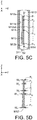
- FIG. 5A is a schematic diagram of the liquid L1 contained in the transmissive container of FIG. 2A being at a medium liquid level.
- FIG. 5B is a schematic diagram of receiving component image M1 captured by the camera of FIG. 5A from a front surface 11f of the transmitting container.
- FIG. 5C is a schematic diagram of the marking component image M12, the first mark image M13 and the second mark image M14 of FIG. 5A .
- FIG. 5D is a schematic diagram of width change in the marking component image M12 of FIG. 5C .
- the steps of the liquid level detecting method of the present embodiment are similar or identical to that of FIGS. 4A-4D , and the difference lies in the determination result of step S240.
- the liquid level determiner 230 determines a position point P i whose width difference value is not within a preset range (that is, the point having abrupt change in width) as a liquid level. As indicated in FIG. 5D , the liquid level determiner 230 sequentially analyzes the width difference W d,l at the position point P i of the marking component width image M12' downward, and determines a point having abrupt change in width (such as position point P 10 ) according to the width difference W d,i . The point having abrupt change in width corresponds to a liquid level of the liquid L1. In the present step, the liquid level determiner 230 can determine a corresponding liquid level value of the liquid L1 at the position point P 10 by looking up a table similar or identical the abovementioned table.
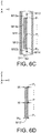
- FIG. 6A is a schematic diagram of the liquid L1 contained in the transmissive container of FIG. 2A being at a medium liquid level.
- FIG. 6B is a schematic diagram of a receiving component image M1 captured by the camera of FIG. 6A from a front surface 11f of the transmitting container captures.
- FIG. 6C is a schematic diagram of the marking component image M12, the first mark image M13 and the second mark image M14 of FIG. 6A .
- FIG. 6D is a schematic diagram of width change in the marking component image M12 of FIG. 6C .
- the steps of the liquid level detecting method of the present embodiment are similar or identical to that of FIGS. 4A-4D , and the difference lies in the determination result of step S240.
- the liquid level determiner 230 determines a position point P i whose width difference value is not within a preset range (that is, the point having abrupt change in width) as a liquid level. As indicated in FIG. 6D , the liquid level determiner 230 determines a position point P i whose width difference value is not within a preset range (that is, the point having abrupt change in width) as a liquid level. As indicated in FIG. 5D , the liquid level determiner 230 sequentially analyzes the width difference W d,l at the position point P i of the marking component width image M12' downward, and determines a point having abrupt change in width (such as the position point P 1 ) according to the width difference W d,i .
- the point having abrupt change in width corresponds to a liquid level of the liquid L1.
- the liquid level detecting device can obtain a plurality of marking component width images at different time points, analyze a plurality of points having abrupt change in width of the marking component width image, and determine the height trend of the liquid level of the liquid L1 contained in the transmissive container 11 according to the trend of the point having abrupt change in width.
- the point having abrupt change in width at the first time point is P 5
- the point having abrupt change in width at the second time point is P 10 . This implies that the liquid level of the liquid L1 contained in the transmissive container 11 at the first time point is higher than the liquid level of the liquid L1 contained in the transmissive container 11 at the second time point.
- the liquid level determiner 230 can determine the change rate of the liquid L1 contained in the transmissive container 11 (such as the rising rate or the falling rate of the liquid level) according to the difference in the liquid level of the liquid L1 contained in the transmissive container 11 within a time difference.
Landscapes
- Engineering & Computer Science (AREA)
- Physics & Mathematics (AREA)
- General Physics & Mathematics (AREA)
- Computer Vision & Pattern Recognition (AREA)
- Theoretical Computer Science (AREA)
- Geometry (AREA)
- Multimedia (AREA)
- Signal Processing (AREA)
- Fluid Mechanics (AREA)
- Measurement Of Levels Of Liquids Or Fluent Solid Materials (AREA)
Abstract
A liquid level detecting method is provided. Firstly, a receiving component is provided, wherein the receiving component includes a transmissive container for containing a liquid and a marking component located on a rear surface of the transmissive container. Then, a camera captures a receiving component image of the receiving component from a front surface of the transmitting container, wherein the receiving component image includes a transmissive container image and a marking component image. Then, the marker component image is analyzed downward from an end portion to obtain multiple width values of multiple position points of the marker component image. Then, a width difference between each width value and a width average of the marking component image is obtained. Then, a position point whose width difference value is not within a preset range is determined. Then, according to the position point, a liquid level of the liquid is determined.
Description
- The invention relates in general to a liquid level detecting method and a liquid level detecting device using the same.
- Generally speaking, the external ventricular drainage system includes a container and a pressure valve connecting the container to a brain chamber. When the brain pressure inside the brain chamber is too large, the pressure valve will be opened, such that the liquid inside the brain chamber can be drained to the container. Different medical orders are provided in response to the change in the liquid level (the brain fluid volume) of the brain fluid inside the container. The medical staff need to be on site to physically observe the change in the liquid level of the brain fluid inside the container and determine what corresponding medical order needs to be taken.
- Therefore, how to provide a device or a method capable of automatically detecting relevant change in liquid level has become a prominent task for the industries.
- According to an embodiment of the present invention, a liquid level detecting method. The liquid level detecting method includes the following steps. Firstly, a transmissive container image of a transmissive container and a marking component image of a marking component are captured by a camera from a front surface of the transmissive container, wherein the transmissive container is configured for containing a liquid, and the marking component is located on a rear surface of the transmissive container. Then, the marker component image is analyzed downward from an end portion of the marker element image to obtain a plurality of width values of a plurality of position points of the marker component image. Then, a width difference between each width value and a width average of the marking component image is obtained. Then, a position point whose width difference value is not within a preset range is determined as the liquid level of the liquid.
- According to another embodiment of the present invention, a liquid level detecting device is provided. The liquid level detecting device is configured for detecting a liquid level of a liquid contained in a transmissive container. A marking component is located on a rear surface of the transmissive container. The liquid level detecting device includes a camera, an image analyzer and a liquid level determiner. The camera is configured for capturing a transmissive container image of the transmissive container and a marking component image of the marking component from a front surface of the transmissive container. The image analyzer is configured for analyzing the marking component image downward from an end portion of the marking component image to obtain a plurality of width values of a plurality of position points of the marker component image and obtaining a width difference between each width value and a width average of the marking component image. The liquid level determiner is configured for determining a position point whose width difference is not within a preset range as the liquid level of the liquid.
- The above and other aspects of the invention will become better understood with regard to the following detailed description of the preferred but non-limiting embodiment (s). The following description is made with reference to the accompanying drawings.
-
-
FIG. 1 is a flowchart of obtaining a width average of a marking component image according to an embodiment of the present disclosure. -
FIG. 2A is a schematic diagram of a liquid level detecting device according to an embodiment of the present disclosure. -
FIG. 2B is a schematic diagram of a transmissive container viewed from a front surface of the transmissive container ofFIG. 2A . -
FIG. 2C is a schematic diagram of a receiving component image captured by the camera ofFIG. 2A from a front surface of atransmissive container 11. -
FIG. 2D is a schematic diagram of the marking component image, the first mark image and the second mark image ofFIG. 2C . -
FIG. 2E is a schematic diagram of a width of the marking component image ofFIG. 2D . -
FIG. 3 is a flowchart of a liquid level detecting method according to an embodiment of the present disclosure. -
FIG. 4A is a schematic diagram of the liquid contained in the transmissive container ofFIG. 2A being at a low liquid level. -
FIG. 4B is a schematic diagram of a receiving component image captured by the camera ofFIG. 4A from a front surface of the transmitting container. -
FIG. 4C is a schematic diagram of the marking component image, the first mark image and the second mark image ofFIG. 4B . -
FIG. 4D is a schematic diagram of width change in the marking component image ofFIG. 4C . -
FIG. 5A is a schematic diagram of the liquid contained in the transmissive container ofFIG. 2A being at a medium liquid level. -
FIG. 5B is a schematic diagram of receiving component image captured by the camera ofFIG. 5A from a front surface of the transmitting container. -
FIG. 5C is a schematic diagram of the marking component image, the first mark image and the second mark image ofFIG. 5A . -
FIG. 5D is a schematic diagram of width change in the marking component image ofFIG. 5C . -
FIG. 6A is a schematic diagram of the liquid contained in the transmissive container ofFIG. 2A being at a medium liquid level. -
FIG. 6B is a schematic diagram of a receiving component image captured by the camera ofFIG. 6A from a front surface of the transmitting container captures. -
FIG. 6C is a schematic diagram of the marking component image, the first mark image and the second mark image ofFIG. 6A . -
FIG. 6D is a schematic diagram of width change in the marking component image ofFIG. 6C . - Refer to
FIG. 1 andFIGS. 2A-2E .FIG. 1 is a flowchart of obtaining a width average Wav of a marking component image M12 according to an embodiment of the present disclosure.FIG. 2A is a schematic diagram of a liquidlevel detecting device 100 according to an embodiment of the present disclosure.FIG. 2B is a schematic diagram of a transmissive container viewed from afront surface 11f of the transmissive container ofFIG. 2A .FIG. 2C is a schematic diagram of a receiving component image M1 captured by the camera ofFIG. 2A from afront surface 11f of atransmissive container 11.FIG. 2D is a schematic diagram of the marking component image M12, the first mark image and the second mark image ofFIG. 2C. FIG. 2E is a schematic diagram of a width of the marking component image M12 ofFIG. 2D . - As indicated in
FIG. 2A , the liquidlevel detecting device 100 includes acamera 110 and animage analyzer 120. The liquidlevel detecting device 100 is configured for detecting a liquid level of a liquid L1 contained in the transmissive container 11 (the liquid L1 is illustrated inFIG. 4A ). The liquidlevel detecting device 100 can be used in medical field such as the external ventricular drainage system for automatically determining the liquid level of the liquid drained to thetransmissive container 11 from the brain chamber. In another embodiment, the liquidlevel detecting device 100 can be used outside the medical field. The liquid level detecting method and the liquid level detecting device using the same disclosed in the embodiments of the present disclosure can be used in any application fields in which corresponding operation is taken according to the observation of the liquid level. - As indicated in
FIG. 2A , the receivingcomponent 10 includes atransmissive container 11, in which a liquid L1 (the liquid L1 is illustrated inFIG. 4A ) is contained, and a markingcomponent 12 located on arear surface 11b of thetransmissive container 11. Thetransmissive container 11 can be realized by a measuring cylinder, a drip-feeding bottle or any liquid container, and the liquid can be body fluid, liquid medicine, water, nutrient solution or other suitable liquid. In the present embodiment, the color of the markingcomponent 12 and that of thetransmissive container 11 can be differentiated from each other. For example, the color of the markingcomponent 12 can be darker than that of thetransmissive container 11, and can be black, blue or other suitable color. - In the present embodiment as indicated in
FIGS. 2A and 2B , the receivingcomponent 10 further includes afirst mark 13 and asecond mark 14, wherein thefirst mark 13 and thesecond mark 14 are located on afront surface 11f of thetransmissive container 11. Additionally, thefirst mark 13, thesecond mark 14 and the markingcomponent 12 are separated from one another. Viewing towards thefront surface 11f as indicated inFIG. 2B , the markingcomponent 12 is located between thefirst mark 13 and thesecond mark 14; thefirst mark 13, thesecond mark 14 and the markingcomponent 12 are separated from one another and do not overlap at all. Besides, the color of thefirst mark 13 and thesecond mark 14 can be similar or identical to that of the markingcomponent 12, and is not repeated here. As indicated inFIG. 2B , thetransmissive container 11 has ascale 11a. Thescale 11a can be located on a lateral side of thetransmissive container 11, such that thescale 11a is least seen (or cannot be seen) in the diagram of the transmissive container viewed from thefront surface 11f (such asFIG. 2B ). Thus, the scale image (if any) will not affect the determination of the liquid level in subsequent step of image analysis. - As indicated in
FIG. 2B , the extending direction S1 of the markingcomponent 12 is substantially parallel to the direction of the connection line S2 connecting thefirst mark 13 and thesecond mark 14. In the present embodiment as indicated inFIG. 2B , thefirst mark 13 is a first triangle; thesecond mark 14 is a second triangle; thebottom side 13e of thefirst mark 13 and thebottom side 14e of thesecond mark 14 are opposite to each other. Furthermore, viewing towards thefront surface 11f, the connection line S2 connecting thefirst mark 13 and thesecond mark 14 passes through the markingcomponent 12. For example, viewing towards thefront surface 11f, the connection line S2 substantially overlaps a first long side 12e1 of the markingcomponent 12. However, in another embodiment, viewing towards thefront surface 11f, the connection line S2 passes through the region between the first long side 12e1 and the second long side 12e2 of the markingcomponent 12. - In step S110, as indicated in
FIG. 2C , thecamera 110 captures a receiving component image M1 of the receivingcomponent 10 from thefront surface 11f of thetransmissive container 11; the receiving component image M1 includes a transmissive container image M11, a marking component image M12, a first mark image M13 and a second mark image M14. - Then, the
image analyzer 120 performs a binary image processing operation on the receiving component image M1. For example, among the pixels of the receiving component image M1 ofFIG. 2C , theimage analyzer 120 sets the pixels of the edge image M11e of the transmissive container image M11, the pixels of the marking component image M12, the pixels of the first mark image M13 and the pixels of the second mark image M14 as the first gray level, and sets the pixels other than the edge image M11e of the transmissive container image M11, the pixels other than the marking component image M12, the pixels other than the first mark image M13 and the pixels other than the second mark image M14 as the second gray level. The second gray level and the first gray level are not the same. In the present embodiment as indicated inFIG. 2D , the first gray level is such as 0 (black, represented by a cross-section), and the second gray level is such as 255 (white, the region other than the cross-section). In another embodiment, the first gray level and/or the second gray level can be any value between 0-255. Refer toFIG. 2D . Due to the transmittance of thetransmissive container 11, only the edge pixels of the transmissive container image M11 are set as the first gray level (the edge image M11e has a darker color and is more obvious), and all or most of the remaining pixels of the transmissive container image M11 are set as the second gray level. Moreover, among the pixels of the receiving component image M1, the pixels of the background image B1 (illustrated inFIG. 2C ) are also set as the first gray level (as indicated inFIG. 2D ). - In step S120, as indicated in
FIG. 2D , theimage analyzer 120 analyzes the marking component image M12 downward from an end portion M12a of the marking component image M12 to obtain a plurality of width values Wi of a plurality of position points Pi of the marking component image M12 as indicated inFIG. 2E , wherein the subscript i indicates the i-th position point. The value of the subscript i can be any positive integer between 1-m, wherein m represents a total number of position points Pi, and can be any positive integer. As indicated inFIG. 2D , the first position point P1 is such as the position of an end portion M12a, and the last position point Pm is such as the position of another end portion M12b of the marking component image M12. In the present embodiment, the end portion M12a is a top end of the marking component image M12, and the end portion M12b is a bottom end of the marking component image M12. - In an embodiment, one of the many methods by which the
image analyzer 120 can obtain the width value Wi is disclosed below. - As indicated in
FIG. 2D and 2E , at each position point Pi, theimage analyzer 120 calculates the width value of each position point within a distance D1 from a starting point, being the connection line S2 connecting the first mark image M13 and the second mark image M14, towards a direction substantially perpendicular to the connection line S2 (such as in a direction towards the second long side image M12e2 of the marking component image M12 to cover the range of the marking component image M12), and calculates the width value Wi of each position point Pi within the range of the distance D1. The range of the distance D1 at least covers the second long side image M12e2 of the marking component image M12, but does not go beyond the edge image M11e of the transmissive container image M11. Since each pixel of the marking component image M12 is already set to the first gray level in the above step, at each position point Pi, theimage analyzer 120 calculates a cumulative count of the pixels having the first gray level within the range of the distance D1, and determines the width value Wi according to the cumulative count of pixels. The larger the number of pixels, the larger the width value Wi. The accumulated width image is illustrated inFIG. 2E . - Besides, since the
first mark 13, thesecond mark 14 and the markingcomponent 12 do not overlap at all, when calculating the cumulative count of the pixels of the marking component image M12, the number of the pixels of the first mark image M13 and the number of the pixels of the second mark image M14 will not be accumulated to the cumulative count of the pixels of the marking component image M12. Therefore, the width value Wi is more accurate. Also, since the range of the distance D1 at least covers the second long side image M12e2 of the marking component image M12, the number of the pixels of the marking component image M12 will be accumulated to the cumulative count of the pixels of the marking component image M12. Since the distance D1 does not go beyond the edge image M11e of the transmissive container image M11, the number of the pixels of the edge image M11e will not be accumulated to the cumulative count of the pixels of the transmissive container image M11. Therefore, the width value Wi is more accurate. To summarize, since the range of the distance D1 at least covers the second long side image M12e2 of the marking component image M12 but does not go beyond the edge image M11e of the transmissive container image M11, all or most of the accumulated pixels are the pixels of the marking component image M12 along the width. Therefore, the obtained width value Wi is more accurate. - Additionally, since the
image analyzer 120 calculates the width value Wi within the range of the distance D1 in a direction substantially perpendicular to the connection line S2, the width value Wi obtained when the receivingcomponent 10 is inclined (for example, the extending direction of the markingcomponent 12 is not parallel to the Z-axis) is similar or identical to the width value Wi obtained when the receivingcomponent 10 is not inclined (for example, the extending direction of the markingcomponent 12 ofFIG. 2B is substantially parallel to the Z-axis). In other words, since theimage analyzer 120 calculates the width value Wi within the range of the distance D1 in a direction substantially perpendicular to the connection line S2, an accurate or consistent determination result of the liquid level can be obtained without considering the relative position/angle between theimage analyzer 120 and the receivingcomponent 10. The Z-axis, which passes the geocentric center or is perpendicular to the ground. For the receiving component image M1 or the transmissive container image M11, the Z-axis is the vertical line. - In step S130, the
image analyzer 120 calculates a plurality of width values Wi according to equation (1) to obtain a width average Wav. In equation (1), m represents a total number of position points, and can be any positive integer equivalent to or greater than 1.

- The liquid level detecting method according to a plurality of embodiments of the present disclosure is disclosed below.
- Refer to
FIG. 3 andFIGS. 4A-4D .FIG. 3 is a flowchart of a liquid level detecting method according to an embodiment of the present disclosure.FIG. 4A is a schematic diagram of the liquid contained in the transmissive container ofFIG. 2A being at a low liquid level.FIG. 4B is a schematic diagram of a receiving component image M1 captured by the camera ofFIG. 4A from afront surface 11f of the transmitting container.FIG. 4C is a schematic diagram of the marking component image M12, the first mark image M13 and the second mark image M14 ofFIG. 4B .FIG. 4D is a schematic diagram of width change in the marking component image M12 ofFIG. 4C . - As indicated in
FIG. 4A , the liquidlevel detecting device 200 includes acamera 110, animage analyzer 120 and aliquid level determiner 230. Theliquid level determiner 230 electrically connects thecamera 110 and theimage analyzer 120 for determining a position point whose width difference is not within a preset range (here below referred as "point having abrupt change in width"), and then determining a liquid level of the liquid L1 according to the point having abrupt change in width. In an embodiment, theimage analyzer 120 and/or theliquid level determiner 230 can be realized by circuits formed by a semiconductor process or can be integrated as a circuit. Also, theimage analyzer 120 and theliquid level determiner 230 can be integrated as a processor or integrated to the central processing unit (CPU). - In step S210, as indicated in
FIG. 4B , thecamera 110 captures a receiving component image M1 of the receivingcomponent 10 from afront surface 11f of thetransmissive container 11, wherein the receiving component image M1 includes a transmissive container image M11, a marking component image M12, a first mark image M13 and a second mark image M14. As indicated inFIG. 4B , the part of the marking component image M12 being blocked by the liquid L1 is magnified due to the refractive index of the liquid L1. Then, theimage analyzer 120 performs a binary image processing operation on the receiving component image M1. - As indicated in
FIG. 4C , among the pixels of the receiving component image M1, theimage analyzer 120 sets the pixels of the edge image M11e of the transmissive container image M11, the pixels of the marking component image M12, the pixels of the first mark image M13 and the pixels of the second mark image M14 as the first gray level, and sets the pixels other than the edge image M11e of the transmissive container image M11, the pixels other than the marking component image M12, the pixels other than the first mark image M13 and the pixels other than the second mark image M14 as the second gray level. The second gray level and the first gray level are not the same. In the present embodiment as indicated inFIG. 4C , the first gray level is such as 0 (black, represented by a cross-section), and the second gray level is such as 255 (white, the region other than the cross-section). In another embodiment, the first gray level and/or the second gray level can be any value between 0-255. Refer toFIG. 4C . Due to the transmittance of thetransmissive container 11 and the liquid L1, only the edge pixels of the transmissive container image M11 are set as the first gray level (the edge image M11e has a darker color and is more obvious), and all or most of the remaining pixels of the transmissive container image M11 are set as the second gray level. Moreover, among the pixels of the receiving component image M1, the pixels of the background image B1 (the background image B1illustrated inFIG. 4B ) are also set as the first gray level (as indicated inFIG. 4C ) - In step S220, as indicated in
FIG. 4C and 4D , theimage analyzer 120 analyzes the marking component image M12 downward from an end portion M12a of the marking component image M12 to obtain a plurality of width values Wi of a plurality of position points Pi of the marking component image M12, wherein the subscript i indicates the i-th position point. As indicated inFIG. 4C , the first position point Pi is such as the position of an end portion M12a, the last position point Pm is such as the position of another end portion M12b of the marking component image M12. In the present embodiment, the end portion M12a is a top end of the marking component image M12, and the end portion M12b is a bottom end of the marking component image M12. - In an embodiment, one of the many methods by which the
image analyzer 120 can obtain the width value Wi is disclosed below. - At each position point Pi, the
image analyzer 120 calculates the width value of each position point within a distance D1 from a starting point, being the connection line S2 connecting the first mark image M13 and the second mark image M14, towards a direction substantially perpendicular to the connection line S2 (such as in a direction towards the second long side image M12e2 of the marking component image M12 to cover the range of the marking component image M12), and calculates the width value Wi of each position point Pi within the range of the distance D1. Since each pixel of the marking component image M12 is already set to the first gray level in the above step, at each position point Pi, theimage analyzer 120 calculates a cumulative count of the pixels having the first gray level within the range of the distance D1, and determines the width value Wi according to the cumulative count of pixels. The larger the number of pixels, the larger the width value Wi. The accumulated width image is illustrated inFIG. 4D . - Besides, since the
image analyzer 120 calculates the width value Wi of each position point Pi within the range of the distance D1 in a direction substantially perpendicular to the connection line S2, the width value Wi obtained when the receivingcomponent 10 is inclined (for example, the extending direction of the markingcomponent 12 is not parallel to the Z-axis) is similar or identical to the width value Wi obtained when the receivingcomponent 10 is not inclined (for example, the extending direction of the markingcomponent 12 ofFIG. 2B is substantially parallel to the Z-axis). - In step S230, the
image analyzer 120 calculates a width difference Wd,i between each width value Wi and a width average Wav of the marking component image M12, wherein the subscript i of the width difference Wd,l indicates the width difference at the position point Pi. The width difference Wd,i at the position point Pi is calculated according to equation (2).

- In step S240, the
liquid level determiner 230 determines a position point Pi whose width difference Wd,i is not within a preset range as a liquid level of the liquid L1. In the present embodiment, the preset range is between a lower limit and an upper limit, wherein the lower limit is such as 0.1 or below, and the upper limit is such as 1.5 or above. - Furthermore, as indicated in equation (2), when the width difference Wd,i is smaller than the lower limit, this implies that the liquid L1 contained in the
transmissive container 11 is at a low liquid level; when the width difference Wd,i is greater than the upper limit, this implies that the liquid L1 contained in thetransmissive container 11 is at a medium liquid level. In the present embodiment as indicated inFIG. 4C , when the liquid L1 contained in thetransmissive container 11 is at the low liquid level, the image of the liquid L1 captured by thecamera 110 is transmissive, and the transmissive container image M11 includes a transmissive image ML1 of the liquid L1 (the pixels of the transmissive image ML1 are at the second gray level). Under such circumstance, the width image ofFIG. 4D (the width represents the number of pixels having the first gray level) will have a point having abrupt change in width, such as position point P15, and the width difference Wd,i at the position point P15 is smaller than the lower limit. - In the present step, as indicated in
FIG. 4D , theliquid level determiner 230 sequentially analyzes the width difference Wd,i at the position point Pi of the marking component width image M12' downward, and determines a point having abrupt change in width (such as position point P15) according to the change in the width difference Wd,i. The point having abrupt change in width corresponds to a liquid level of the liquid L1. - In the present step, the
liquid level determiner 230 can determine the corresponding liquid level value of the liquid L1 at the position point P15 by looking up a table (not illustrated). In an embodiment, the table includes the correspondence relationship between a plurality of position points P15 and a plurality of liquid level values, wherein the height of the liquid level corresponds to thescale 11a (illustrated inFIG. 2B ) of thetransmissive container 11. In other words, the liquid level value at the position point P15 determined by theliquid level determiner 230 is consistent with the scale value of the liquid level of the liquid L1 contained in thetransmissive container 11. For example, if the liquid level value at the position point P15 determined by theliquid level determiner 230 is 5 ml, this implies that the scale value of the liquid level of the liquid L1 contained in thetransmissive container 11 is also 5 ml or near 5 ml. The abovementioned table can be obtained through experiments or simulation, and can be stored in a storage unit inside or outside theliquid level determiner 230. - In another embodiment, the
liquid level determiner 230 determines whether the liquid level value reaches a preset liquid level value. When the liquid level value reaches the preset liquid level value, theliquid level determiner 230 can emit a signal to notify the medical staff to be on site and perform a corresponding operation such as a corresponding medical order. In an embodiment, the liquidlevel detecting device 100 further includes a notifier (not illustrated), which emits a notification signal according to the signal of theliquid level determiner 230 to notify the medical staff to be on site and perform a corresponding operation. The notifier can be realized by such as a sound generator, a display, or a vibrator, and the notification signal can be realized by such as sound, image, or vibration. - Refer to
FIG. 3 andFIGS. 5A-5D .FIG. 5A is a schematic diagram of the liquid L1 contained in the transmissive container ofFIG. 2A being at a medium liquid level.FIG. 5B is a schematic diagram of receiving component image M1 captured by the camera ofFIG. 5A from afront surface 11f of the transmitting container.FIG. 5C is a schematic diagram of the marking component image M12, the first mark image M13 and the second mark image M14 ofFIG. 5A .FIG. 5D is a schematic diagram of width change in the marking component image M12 ofFIG. 5C . - The steps of the liquid level detecting method of the present embodiment are similar or identical to that of
FIGS. 4A-4D , and the difference lies in the determination result of step S240. - In step S240 of the present embodiment, the
liquid level determiner 230 determines a position point Pi whose width difference value is not within a preset range (that is, the point having abrupt change in width) as a liquid level. As indicated inFIG. 5D , theliquid level determiner 230 sequentially analyzes the width difference Wd,l at the position point Pi of the marking component width image M12' downward, and determines a point having abrupt change in width (such as position point P10) according to the width difference Wd,i. The point having abrupt change in width corresponds to a liquid level of the liquid L1. In the present step, theliquid level determiner 230 can determine a corresponding liquid level value of the liquid L1 at the position point P10 by looking up a table similar or identical the abovementioned table. - Refer to
FIG. 3 andFIGS. 6A-6D .FIG. 6A is a schematic diagram of the liquid L1 contained in the transmissive container ofFIG. 2A being at a medium liquid level.FIG. 6B is a schematic diagram of a receiving component image M1 captured by the camera ofFIG. 6A from afront surface 11f of the transmitting container captures.FIG. 6C is a schematic diagram of the marking component image M12, the first mark image M13 and the second mark image M14 ofFIG. 6A .FIG. 6D is a schematic diagram of width change in the marking component image M12 ofFIG. 6C . - The steps of the liquid level detecting method of the present embodiment are similar or identical to that of
FIGS. 4A-4D , and the difference lies in the determination result of step S240. - In step S240 of the present embodiment, the
liquid level determiner 230 determines a position point Pi whose width difference value is not within a preset range (that is, the point having abrupt change in width) as a liquid level. As indicated inFIG. 6D , theliquid level determiner 230 determines a position point Pi whose width difference value is not within a preset range (that is, the point having abrupt change in width) as a liquid level. As indicated inFIG. 5D , theliquid level determiner 230 sequentially analyzes the width difference Wd,l at the position point Pi of the marking component width image M12' downward, and determines a point having abrupt change in width (such as the position point P1) according to the width difference Wd,i. The point having abrupt change in width corresponds to a liquid level of the liquid L1. In the present step, theliquid level determiner 230 can determine a corresponding liquid level value of the liquid L1 at the position point P1 by looking up a table similar or identical the abovementioned table. Since the liquid level corresponds to the first position point (i=1), theliquid level determiner 230 can determine that the liquid L1 contained in thetransmissive container 11 is at a full water level. - In another embodiment, when the point having abrupt change in width is the last position point Pm, this implies that the liquid L1 contained in the
transmissive container 11 is completely or nearly depleted. Additionally, when each width difference Wd,l is within the preset range, that is, no point has abrupt change in width, this implies that that the liquid L1 contained in thetransmissive container 11 is completely or nearly depleted. - Along with the change in the liquid level, the liquid level detecting device can obtain a plurality of marking component width images at different time points, analyze a plurality of points having abrupt change in width of the marking component width image, and determine the height trend of the liquid level of the liquid L1 contained in the
transmissive container 11 according to the trend of the point having abrupt change in width. For example, the point having abrupt change in width at the first time point is P5, and the point having abrupt change in width at the second time point is P10. This implies that the liquid level of the liquid L1 contained in thetransmissive container 11 at the first time point is higher than the liquid level of the liquid L1 contained in thetransmissive container 11 at the second time point. Thus, theliquid level determiner 230 can determine the change rate of the liquid L1 contained in the transmissive container 11 (such as the rising rate or the falling rate of the liquid level) according to the difference in the liquid level of the liquid L1 contained in thetransmissive container 11 within a time difference. - While the invention has been described by way of example and in terms of the preferred embodiment (s), it is to be understood that the invention is not limited thereto. On the contrary, it is intended to cover various modifications and similar arrangements and procedures, and the scope of the appended claims therefore should be accorded the broadest interpretation so as to encompass all such modifications and similar arrangements and procedures.
Claims (15)
- A liquid level detecting method, comprising:capturing a transmissive container image (M11) of a transmissive container (11) and a marking component image (M12) of a marking component (M12) from a front surface (11f) of a transmissive container (11) by a camera (110), wherein the transmissive container (11) is configured for containing a liquid (L1), and the marking component (M12) is located on a rear surface (11b) of the transmissive container (11);analyzing the marking component image (M12) downward from an end portion (M12a, M12b) of the marking component image (M12) to obtain a plurality of width values (Wi) of a plurality of position points (Pm) of the marker component image (M12);obtaining a width difference (Wd,i) between each width value (Wi) and a width average (Wav) of the marking component image (M12); anddetermining the position point (Pm) whose width difference (Wd,i) is not within a preset range as a liquid level of the liquid (L1).
- The liquid level detecting method according to claim 1, further comprising:setting each of pixels of the transmissive container image (M11) and the marking component image (M12) to a first gray level; andsetting each of pixels other than the pixels of the transmissive container image (M11) and the marking component image (M12) to a second gray level different from the first gray level;wherein the step of obtaining the width values (Wi) of the position points (Pm) of the marking component image (M12) comprises:at each position point (Pm), calculating a cumulative count of the pixels of the marking component image (M12) that have the first gray level and determining the width value (Wi) according to the cumulative count of pixels.
- The liquid level detecting method according to claim 1, wherein a first mark (13) and a second mark (14) are located on a front surface (11f) of the transmissive container (11); the step of capturing the transmissive container image (M11) from the front surface (11f) by the camera (110) further comprises capturing a first mark image (M13) of the first mark (13) and a second mark image (M14) of the second mark (14); the step of analyzing the marking component image (M12) downward from an end portion (M12a, M12b) of the marking component image (M12) further comprises:at each position point (Pm), calculating the width value (Wi) of each position point (Pm) from a starting point, being a connection line connecting the first mark image (M13) and the second mark image (M14), towards a direction substantially perpendicular to the connection line (S2).
- The liquid level detecting method according to claim 3, wherein the step of calculating the width value (Wi) of each position point (Pm) further comprises:at each position point (Pm), calculating the width value (Wi) within the range of a distance towards a direction substantially perpendicular to the connection line (S2).
- The liquid level detecting method according to claim 1, the first mark (13) and the second mark (14) are located on a front surface (11f) of the transmissive container (11); the extending direction (S1) of the marking component (12) is substantially parallel to the direction of a connection line (S2) connecting the first mark (13) and the second mark (14).
- The liquid level detecting method according to claim 5, wherein the first mark (13) is a first triangle; the second mark (14) is a second triangle; the bottom side (13e) of the first mark (13) and the bottom side (14e) of the second mark (14) are opposite to each other.
- The liquid level detecting method according to claim 1, wherein the preset range is between 0.1-1.5.
- A liquid level detecting device (100, 200) for detecting a liquid level of a liquid (L1) contained in a transmissive container (11), wherein a marking component (12) is located on a rear surface (11b) of the transmissive container (11), and the liquid level detecting device (100, 200) comprises:a camera (110) for capturing a transmissive container image (M11) of a transmissive container (11) and a marking component image (M12) of a marking component (12) from a front surface (11f) of a transmissive container (11);an image analyzer (120) for:analyzing the marking component image (M12) downward from an end portion (M12a, M12b) of the marking component image (M12) to obtain a plurality of width values (Wi) of a plurality of position points (Pm) of the marker component image (M12); andobtaining a width difference (Wd,i) between each width value (Wi) and a width average (Wav) of the marking component image (M12); anda liquid level determiner (230) configured for:determining the position point (Pm) whose width difference (Wd,i) is not within a preset range as the liquid level of the liquid (L1).
- The liquid level detecting device (100, 200) according to claim 8, wherein the image analyzer (120) further is configured for:setting each of the pixels of the transmissive container image (M11) and the marking component image (M12) to a first gray level; andsetting each of the pixels other than the pixels of the transmissive container image (M11) and the marking component image (M12) to a second gray level different from the first gray level;wherein the step of obtaining the width values (Wi) of the position points (Pm) of the marking component image (M12) comprises:at each position point (Pm), calculating a cumulative count of the pixels of the marking component image (M12) that have the first gray level and determining the width value (Wi) according to the cumulative count of pixels.
- The liquid level detecting device (100, 200) according to claim 8, wherein a first mark (13) and a second mark (14) are located on a front surface (11f) of the transmissive container (11); the camera (110) further is configured for capturing a first mark image (M13) of the first mark (13) and a second mark image (M14) of the second mark (14) from the front surface (11f) of the transmissive container (11); the image analyzer (120) further is configured for:at each position point (Pm), calculating the width value (Wi) of each position point (Pm) from a starting point, being a connection line connecting the first mark image (M13) and the second mark image (M14), towards a direction substantially perpendicular to the connection line.
- The liquid level detecting device (100, 200) according to claim 10, wherein the image analyzer (120) further is configured for:at each position point (Pm), calculating the width value (Wi) within the range of a distance towards a direction substantially perpendicular to the connection line (S2).
- The liquid level detecting device (100, 200) according to claim 8, wherein a first mark (13) and a second mark (14) are located on a front surface (11f) of the transmissive container (11); the extending direction of the marking component (12) is substantially parallel to the direction of a connection line (S2) connecting the first mark (13) and the second mark (14).
- The liquid level detecting device (100, 200) according to claim 12, wherein the first mark (13) is a first triangle; the second mark (14) is a second triangle; the bottom side (13e) of the first mark (13) and the bottom side (14e) of the second mark (14) are opposite to each other.
- The liquid level detecting device (100, 200) according to claim 12, wherein the first mark (13), the second mark (14) and the marking component (12) are separated from one another.
- The liquid level detecting device (100, 200) according to claim 8, wherein the preset range is between 0.1-1.5.
Applications Claiming Priority (1)
| Application Number | Priority Date | Filing Date | Title |
|---|---|---|---|
| TW107132130A TWI670473B (en) | 2018-09-12 | 2018-09-12 | Liquid level detecting method and device using the same |
Publications (1)
| Publication Number | Publication Date |
|---|---|
| EP3623989A1 true EP3623989A1 (en) | 2020-03-18 |
Family
ID=68619166
Family Applications (1)
| Application Number | Title | Priority Date | Filing Date |
|---|---|---|---|
| EP19151932.1A Withdrawn EP3623989A1 (en) | 2018-09-12 | 2019-01-15 | Liquid level detecting method and device using the same |
Country Status (4)
| Country | Link |
|---|---|
| US (1) | US10699433B2 (en) |
| EP (1) | EP3623989A1 (en) |
| CN (1) | CN110895164A (en) |
| TW (1) | TWI670473B (en) |
Families Citing this family (3)
| Publication number | Priority date | Publication date | Assignee | Title |
|---|---|---|---|---|
| TWI784730B (en) * | 2021-09-28 | 2022-11-21 | 金寶電子工業股份有限公司 | Detection method for level of print material tank |
| US12616080B2 (en) | 2022-08-02 | 2026-05-05 | Cnh Industrial Canada, Ltd. | Compartment profile monitoring and control system for an agricultural system |
| CN117268498B (en) * | 2023-11-20 | 2024-01-23 | 中国航空工业集团公司金城南京机电液压工程研究中心 | An oil quantity measurement method and system |
Citations (1)
| Publication number | Priority date | Publication date | Assignee | Title |
|---|---|---|---|---|
| US20180068460A1 (en) * | 2016-09-06 | 2018-03-08 | Taiwan Intelligent Robotic Company, Ltd. | Liquid Level Detecting System and Method thereof |
Family Cites Families (22)
| Publication number | Priority date | Publication date | Assignee | Title |
|---|---|---|---|---|
| US6098029A (en) * | 1994-06-14 | 2000-08-01 | Hitachi, Ltd. | Liquid-level position measuring method and system |
| JP2000283824A (en) * | 1999-03-31 | 2000-10-13 | Suzuki Motor Corp | Container information measuring device |
| JP2005291830A (en) * | 2004-03-31 | 2005-10-20 | Shinko Engineering & Maintenance Co Ltd | Image measurement apparatus and image measurement method for liquid level |
| US7499581B2 (en) | 2005-02-10 | 2009-03-03 | Forhealth Technologies, Inc. | Vision system to calculate a fluid volume in a container |
| EP2228633B1 (en) * | 2009-03-10 | 2017-07-05 | Nestec S.A. | Optical level detector for a beverage machine |
| US8184848B2 (en) | 2009-06-17 | 2012-05-22 | National Applied Research Laboratories | Liquid level detection method |
| KR100998885B1 (en) | 2009-11-19 | 2010-12-08 | 한국건설기술연구원 | Liquid interface recognition method using the change of concentration distribution of temporal pixel of image and liquid height recognition device to recognize liquid height using it |
| CN102116664B (en) * | 2009-12-30 | 2013-11-06 | 捷达世软件(深圳)有限公司 | Water level monitoring system and method |
| KR101060031B1 (en) * | 2011-02-09 | 2011-08-29 | (주)유디피 | Water level monitoring device and method |
| JP5711564B2 (en) * | 2011-02-17 | 2015-05-07 | ベックマン コールター, インコーポレイテッド | Automatic analyzer |
| EP2702355A4 (en) * | 2011-04-25 | 2014-12-31 | John William Ladd | Systems, methods, and computer-readable media for three-dimensional fluid scanning |
| US20120281096A1 (en) * | 2011-05-02 | 2012-11-08 | Honeywell-Enraf B.V. | Storage tank inspection system and method |
| ES3056354T3 (en) * | 2012-05-14 | 2026-02-19 | Stryker Corp | System and method for estimating a quantity of a blood component in a fluid canister |
| CN103134568B (en) | 2013-01-17 | 2015-09-30 | 厦门优迈科医学仪器有限公司 | A kind of detection method of liquid level and equipment thereof |
| BR102013006794B1 (en) | 2013-03-25 | 2022-11-01 | Luxtec - Sistemas Ópticos Ltda - Me | MULTIPARAMETRIC DEVICE FOR MEASURING, BY OPTICAL MEANS, THE FILLING LEVEL OF TANKS AND RESERVOIRS FOR LIQUIDS AND LIQUEFIEDS, REFRACTIVE INDEX AND IMAGE ANALYSIS, WITHOUT MOVING PARTS |
| TWI473976B (en) | 2013-06-28 | 2015-02-21 | Univ Nat Taiwan Ocean | Module for measuring the height of a liquid surface |
| US9459130B2 (en) * | 2013-11-13 | 2016-10-04 | Deere & Company | System for measuring a liquid level and orientation |
| CN104819754B (en) * | 2015-05-13 | 2017-09-29 | 山东大学 | A kind of medicine bottle liquid-level detecting method based on image procossing |
| GB2538539A (en) * | 2015-05-20 | 2016-11-23 | Airbus Operations Ltd | Measuring surface of a liquid |
| CN205192571U (en) * | 2015-12-18 | 2016-04-27 | 东莞理工学院 | A liquid level measuring device based on CCD |
| TWI590190B (en) | 2016-05-26 | 2017-07-01 | 財團法人成大水利海洋研究發展文教基金會 | Method for image recognition of liquid |
| CN106197612B (en) * | 2016-07-25 | 2019-09-03 | 江苏科技大学 | A liquid level detection method for transparent bottles based on machine vision |
-
2018
- 2018-09-12 TW TW107132130A patent/TWI670473B/en active
- 2018-09-27 CN CN201811129950.9A patent/CN110895164A/en active Pending
- 2018-11-23 US US16/199,064 patent/US10699433B2/en active Active
-
2019
- 2019-01-15 EP EP19151932.1A patent/EP3623989A1/en not_active Withdrawn
Patent Citations (1)
| Publication number | Priority date | Publication date | Assignee | Title |
|---|---|---|---|---|
| US20180068460A1 (en) * | 2016-09-06 | 2018-03-08 | Taiwan Intelligent Robotic Company, Ltd. | Liquid Level Detecting System and Method thereof |
Also Published As
| Publication number | Publication date |
|---|---|
| TWI670473B (en) | 2019-09-01 |
| US20200082558A1 (en) | 2020-03-12 |
| TW202011003A (en) | 2020-03-16 |
| US10699433B2 (en) | 2020-06-30 |
| CN110895164A (en) | 2020-03-20 |
Similar Documents
| Publication | Publication Date | Title |
|---|---|---|
| US10699433B2 (en) | Liquid level detecting method and device using the same | |
| US20180068460A1 (en) | Liquid Level Detecting System and Method thereof | |
| US20200184192A1 (en) | Image analysis apparatus, image analysis method, and image analysis program | |
| US9812080B2 (en) | Driving mode switching method and module, and display device | |
| US20210142490A1 (en) | Information processing apparatus, control method, and program | |
| RS61389B1 (en) | Break analysis apparatus and method | |
| CN113298089A (en) | Venous transfusion liquid level detection method based on image processing | |
| WO2019061659A1 (en) | Method and device for removing eyeglasses from facial image, and storage medium | |
| KR101991452B1 (en) | Method for detecting nipple location, method for displaying breast image and apparatus for detecting nipple location | |
| CN114581653B (en) | A liquid level detection method, device, medium and product for microplate | |
| KR20220100302A (en) | Image processing method for counting pill | |
| CN119048323A (en) | Water output control method, device, water dispenser and storage medium | |
| CN113470015B (en) | Water body shaking detection and analysis method and system based on image processing | |
| CN114882348A (en) | Method for identifying information of articles in refrigerator, refrigerator and computer storage medium | |
| JP7324485B2 (en) | Droplet measurement system, droplet measurement method, and program | |
| CN116457840A (en) | Image analysis server, object counting method using image analysis server, and object counting system | |
| US20150169970A1 (en) | Image processing apparatus and image processing method | |
| CN110210291B (en) | Guide vane parameter acquisition method and device, electronic equipment and storage medium | |
| CN109901716A (en) | Sight line point prediction model method for building up, device and sight line point prediction technique | |
| CN107462301A (en) | Liquid level monitoring method | |
| JP2017084302A (en) | Iris position detection device, electronic apparatus, program, and iris position detection method | |
| CN115239789B (en) | Method and device for determining liquid volume, storage medium and terminal | |
| CN104866808B (en) | Human eye positioning method and device | |
| CN108205669B (en) | Nematode recognition methods and device | |
| CN111695551B (en) | Dial reading method, device, computer equipment and readable storage medium |
Legal Events
| Date | Code | Title | Description |
|---|---|---|---|
| PUAI | Public reference made under article 153(3) epc to a published international application that has entered the european phase |
Free format text: ORIGINAL CODE: 0009012 |
|
| STAA | Information on the status of an ep patent application or granted ep patent |
Free format text: STATUS: REQUEST FOR EXAMINATION WAS MADE |
|
| 17P | Request for examination filed |
Effective date: 20190115 |
|
| AK | Designated contracting states |
Kind code of ref document: A1 Designated state(s): AL AT BE BG CH CY CZ DE DK EE ES FI FR GB GR HR HU IE IS IT LI LT LU LV MC MK MT NL NO PL PT RO RS SE SI SK SM TR |
|
| AX | Request for extension of the european patent |
Extension state: BA ME |
|
| STAA | Information on the status of an ep patent application or granted ep patent |
Free format text: STATUS: THE APPLICATION IS DEEMED TO BE WITHDRAWN |
|
| 18D | Application deemed to be withdrawn |
Effective date: 20200919 |