EP3623853B1 - Connection detecting mechanism of optical connector plug - Google Patents
Connection detecting mechanism of optical connector plug Download PDFInfo
- Publication number
- EP3623853B1 EP3623853B1 EP19192536.1A EP19192536A EP3623853B1 EP 3623853 B1 EP3623853 B1 EP 3623853B1 EP 19192536 A EP19192536 A EP 19192536A EP 3623853 B1 EP3623853 B1 EP 3623853B1
- Authority
- EP
- European Patent Office
- Prior art keywords
- optical
- connector plug
- optical connector
- state
- connection detecting
- Prior art date
- Legal status (The legal status is an assumption and is not a legal conclusion. Google has not performed a legal analysis and makes no representation as to the accuracy of the status listed.)
- Not-in-force
Links
- 230000003287 optical effect Effects 0.000 title claims description 383
- 230000007246 mechanism Effects 0.000 title claims description 31
- 230000008878 coupling Effects 0.000 claims description 28
- 238000010168 coupling process Methods 0.000 claims description 28
- 238000005859 coupling reaction Methods 0.000 claims description 28
- 238000001514 detection method Methods 0.000 claims 2
- 238000004891 communication Methods 0.000 description 22
- 238000000605 extraction Methods 0.000 description 13
- 238000003780 insertion Methods 0.000 description 8
- 230000037431 insertion Effects 0.000 description 8
- 238000000034 method Methods 0.000 description 5
- 230000005540 biological transmission Effects 0.000 description 4
- 230000006835 compression Effects 0.000 description 4
- 238000007906 compression Methods 0.000 description 4
- 239000000758 substrate Substances 0.000 description 4
- 230000014759 maintenance of location Effects 0.000 description 3
- 239000013307 optical fiber Substances 0.000 description 3
- 229920005989 resin Polymers 0.000 description 3
- 239000011347 resin Substances 0.000 description 3
- 238000012800 visualization Methods 0.000 description 3
- 210000003323 beak Anatomy 0.000 description 2
- 239000002184 metal Substances 0.000 description 2
- 230000002093 peripheral effect Effects 0.000 description 2
- 239000004033 plastic Substances 0.000 description 2
- 229920003023 plastic Polymers 0.000 description 2
- 230000000630 rising effect Effects 0.000 description 2
- 229920003002 synthetic resin Polymers 0.000 description 2
- 239000000057 synthetic resin Substances 0.000 description 2
- 230000003321 amplification Effects 0.000 description 1
- 230000004397 blinking Effects 0.000 description 1
- 239000003086 colorant Substances 0.000 description 1
- 230000001419 dependent effect Effects 0.000 description 1
- 238000011161 development Methods 0.000 description 1
- 230000018109 developmental process Effects 0.000 description 1
- 230000000694 effects Effects 0.000 description 1
- 239000000835 fiber Substances 0.000 description 1
- 210000001503 joint Anatomy 0.000 description 1
- 238000004519 manufacturing process Methods 0.000 description 1
- 239000000463 material Substances 0.000 description 1
- 230000013011 mating Effects 0.000 description 1
- 238000003199 nucleic acid amplification method Methods 0.000 description 1
- 238000005192 partition Methods 0.000 description 1
- 230000000149 penetrating effect Effects 0.000 description 1
- 238000003825 pressing Methods 0.000 description 1
- 230000000717 retained effect Effects 0.000 description 1
Images











Classifications
-
- G—PHYSICS
- G02—OPTICS
- G02B—OPTICAL ELEMENTS, SYSTEMS OR APPARATUS
- G02B6/00—Light guides; Structural details of arrangements comprising light guides and other optical elements, e.g. couplings
- G02B6/24—Coupling light guides
- G02B6/36—Mechanical coupling means
- G02B6/38—Mechanical coupling means having fibre to fibre mating means
- G02B6/3807—Dismountable connectors, i.e. comprising plugs
- G02B6/3833—Details of mounting fibres in ferrules; Assembly methods; Manufacture
- G02B6/385—Accessories for testing or observation of connectors
-
- G—PHYSICS
- G02—OPTICS
- G02B—OPTICAL ELEMENTS, SYSTEMS OR APPARATUS
- G02B6/00—Light guides; Structural details of arrangements comprising light guides and other optical elements, e.g. couplings
- G02B6/24—Coupling light guides
- G02B6/36—Mechanical coupling means
- G02B6/38—Mechanical coupling means having fibre to fibre mating means
- G02B6/3807—Dismountable connectors, i.e. comprising plugs
- G02B6/3895—Dismountable connectors, i.e. comprising plugs identification of connection, e.g. right plug to the right socket or full engagement of the mating parts
-
- G—PHYSICS
- G02—OPTICS
- G02B—OPTICAL ELEMENTS, SYSTEMS OR APPARATUS
- G02B6/00—Light guides; Structural details of arrangements comprising light guides and other optical elements, e.g. couplings
- G02B6/24—Coupling light guides
- G02B6/36—Mechanical coupling means
- G02B6/38—Mechanical coupling means having fibre to fibre mating means
- G02B6/3807—Dismountable connectors, i.e. comprising plugs
- G02B6/381—Dismountable connectors, i.e. comprising plugs of the ferrule type, e.g. fibre ends embedded in ferrules, connecting a pair of fibres
- G02B6/3825—Dismountable connectors, i.e. comprising plugs of the ferrule type, e.g. fibre ends embedded in ferrules, connecting a pair of fibres with an intermediate part, e.g. adapter, receptacle, linking two plugs
-
- G—PHYSICS
- G02—OPTICS
- G02B—OPTICAL ELEMENTS, SYSTEMS OR APPARATUS
- G02B6/00—Light guides; Structural details of arrangements comprising light guides and other optical elements, e.g. couplings
- G02B6/24—Coupling light guides
- G02B6/36—Mechanical coupling means
- G02B6/38—Mechanical coupling means having fibre to fibre mating means
- G02B6/3807—Dismountable connectors, i.e. comprising plugs
- G02B6/3873—Connectors using guide surfaces for aligning ferrule ends, e.g. tubes, sleeves, V-grooves, rods, pins, balls
- G02B6/3874—Connectors using guide surfaces for aligning ferrule ends, e.g. tubes, sleeves, V-grooves, rods, pins, balls using tubes, sleeves to align ferrules
- G02B6/3877—Split sleeves
Definitions
- the present invention relates to a connection detecting mechanism of an optical connector plug which is interconnected by an optical adapter, for example, at the downsized high-density mounting time.
- connection detecting mechanisms of optical connector plugs which can securely prevent the optical connector plug from being erroneously disconnected from an optical adapter at the normal fitting time as well as previously avoiding a half-inserted state of the optical connector plug when being fitted to the optical adapter.
- an optical adapter for coupling an optical connector plug structured such that an adapter sleeve and an adapter latch are provided within an adapter main body, an optical connector plug having a ferrule is inserted into the adapter main body, and a head portion of the adapter latch gets over a head portion of the connector latch or the head portion and a plate-like portion of the connector latch and is engaged with the connector latch, thereby connecting the optical connector plug, being rotated around a connection element rotation supporting point and a rotary display portion rotation supporting point by a lifting motion of the head portion of the adapter latch, and rotationally amplifying an amount of lifting motion of the adapter latch.
- the rotary display portion is rotated by a connection element and the optical adapter displays on the rotary display surface a half-inserted state when the adapter latch runs on the connector latch or the plate-like portion with an operating amount of the rotational amplification.
- an optical adapter for coupling an optical connector plug structured such that a head portion of an optical adapter latch of the optical adapter is lifted up by a head portion of an optical connector latch when the optical connector plug is inserted into the optical adapter, and comes into contact with each other in their head portion leading ends without the head portion of the optical adapter latch engaging with the head portion of the optical connector latch, and both the latches are at a half insertion state position which is different from a position where both the latch are engaged, thereby mechanically rotating and amplifying an amount of lifting motion of the adapter latch and displaying a position of the amplified amount of motion.
- an adapter for detecting communication light for a duplex LC including a first light extraction hole in which a first optical transmission line is arranged among two optical transmission lines of which a part of communication light is taken out as leakage light when the duplex LC connector is fitted ad inserted, and which takes the leakage light out of a first space which is comparted by a first wall surface and is isolated from the other space, a second light extraction hole in which a second optical transmission line is arranged among the two optical transmission lines and which takes the leakage light out of a second space which is comparted by a second wall surface and is isolated from the other space, the first light extraction hole and the second light extraction hole being provided on an upper wall surface of an adapter main body which is opaque against the light, and a communication light detector having a first light receiving element which is fitted and attached to the first light extraction hole, and a second light receiving element which is fitted and attached to the second light extraction hole, wherein the first light
- a communication light detector attached via an attachment to a light extraction hole which is formed in an upper wall surface of a communication light visualization adapter, receiving through the light extraction hole the leakage light which a part of the communication light transmitted via the communication light visualization adapter is taken out of, and provided in an upper surface of a display portion with a pilot lamp for detecting whether or not the communication light is transmitted via the communication light visualization adapter.
- Patent literature document US 2018/136410 A1 discloses a connector engagement sensing mechanism.
- a connector assembly includes an adapter, a housing device, a ferrule assembly, and a sensor.
- the housing device is received by the adapter and has a bore, a front end, and a rear end opposite the front end.
- a ferrule of the ferrule assembly is within the bore of the housing device and has a mating end extending beyond the front end of the housing device.
- the sensor is mounted on the rear end of the housing, the rear end of the ferrule assembly, or on the adapter confronting and spaced apart from the housing device or the ferrule assembly.
- the sensor is configured for detecting a force applied by the housing device or the ferrule assembly, respectively.
- An electrical characteristic of the sensor changes to indicate a predetermined force has been applied by the housing device or the ferrule assembly, respectively.
- the communication light detector is provided in an upper wall surface of the adapter main body, the communication light detector being constructed by the first light extraction hole which takes out the leakage light from the first space, and the second light extraction hole which takes out the leakage light from the second space, it is hard to view from the front face of the communication light detector in the downsized high-density mounting optical adapter a lot of which are overlapped in the vertical direction.
- the rotary display portions of document JP 4 685 972 B and document JP 4 588 805 B mentioned above are individually provided in each of the optical adapters, and the communication light detectors of document JP 6 219 219 B and the patent literature 4 are individually attached to each of the optical adapters.
- the light reflection layer and the position adjusting groove are provided, and in the communication light detector of document JP 6 229 549 B , the light receiving element is provided.
- a complicated structure is required, and a product cost and a manufacturing cost are expensive.
- an object of the present invention is to provide a connection detecting mechanism of an optical connector plug in an optical adapter which can be mounted in a downsized high-density manner, in which the connection detecting mechanism of the optical connector plug can resolve the conventional troublesome work of individually attaching the detecting device to the optical adapter by structuring such as to easily confirm visually from a front face side of the optical adapter whether or not the optical connector plug is in a half-inserted state, prevent the poor connection accident from being generated in all the optical adapter, and attach a connection detecting device according to a single configuration so as to be used in common over all the optical adapter which are adjacent in a lateral direction.
- connection detecting mechanism according to claim 1.
- connection detecting device is formed an outer shape thereof into a rectangular housing shape, and is provided in both front and rear ends of the lower face with the switch lever for detecting connection, and the light emission display portion in the front face of the connection detecting device is formed as a pair of light emission display portions in upper and lower positions in correspondence to the fitting portions in both ends of the optical adapter.
- Horizontal guide keys are provided in both right and left side faces of the connection detecting device, a screw attaching flange portion for fixing to the optical adapter panel is provided at a position which is away from the guide keys, and guide grooves for inserting the guide keys from a forward side of the optical adapter panel are formed at opposing positions of right and left inner edges in the attaching recess of the optical adapter panel.
- Downward projections are provided in both front and rear ends of the lower face of the connection detecting device, hole portions are provided in upper wall sides of opening ends in both the fitting portions of the optical adapter, and the projections and the hole portions are formed in such a manner as to position the optical adapter in relation to the connection detecting device by moving downward the connection detecting device in relation to the optical adapter panel in a state in which the connection detecting device is locked by the screw attaching flange portion, and fitting the projections to the hole portions.
- the optical connector plug is an LC-type optical connector plug in which a latch lever detachably engaging with the optical adapter is formed in an upper surface in a longitudinal direction of the optical connector plug from a forward side toward a rearward side, the latch lever pushes up a switch lever of the connection detecting device so as to change from a switch-off state to a switch-on state when the optical connector plug is fully inserted into the fitting portion of the optical adapter instead of being in a half-inserted state, and the optical connector plug is formed in such a manner that a lighting color of the on-state is displayed on a light emission display portion in the front face.
- the optical connector plug is an MPO-type optical connector plug having a tubular coupling which is outward inserted into a sleeve-shaped housing having a ferrule housed in a leading end thereof and is provided slidably in a movable range which is secured in an axial direction of the housing, the coupling pushes up a switch lever of the connection detecting device so as to change from a switch-off state to a switch-on state when the optical connector plug is fully inserted into the fitting portion of the optical adapter instead of being in a half-inserted state, and the optical connector plug is formed in such a manner that a lighting color of the on-state is displayed on a light emission display portion in the front face.
- the optical connector plug is an MU-type optical connector plug structured such that a knob is outward installed to an outer side of a plug frame and the plug frame can slide at a desired stroke in an axial direction within the know, the knob pushes up a switch lever of the connection detecting device so as to change from a switch-off state to a switch-on state when the connector plug is fully inserted into the fitting portion of the optical adapter instead of being in a half-inserted state, and the optical connector plug is formed in such a manner that a lighting color of the on-state is displayed on a light emission display portion in the front face.
- the optical connector plug is an SC-type optical connector plug in which a ferrule is inward installed within a plug frame attached to an inner portion of a knob, a guide projection formed in the center of an upper surface of the knob pushes up a switch lever of the connection detecting device so as to change from a switch-off state to a switch-on state when the optical connector plug is fully inserted into the fitting portion of the optical adapter instead of being in a half-inserted state, and the optical connector plug is formed in such a manner that a lighting color of the on-state is displayed on a light emission display portion in the front face.
- the optical adapter which can be mounted in a downsized high-density manner, it is possible to resolve the conventional troublesome work of individually attaching the detecting device to the optical adapter by structuring such as to easily confirm visually from the front face side of the optical adapter whether or not the optical connector plug is in the half-inserted state, prevent the poor connection accident from being generated in all the optical adapter, and attach the connection detecting device according to the single configuration so as to be used in common over all the optical adapter which are adjacent in the lateral direction.
- structuring such as to easily confirm visually from the front face side of the optical adapter whether or not the optical connector plug is in the half-inserted state, prevent the poor connection accident from being generated in all the optical adapter, and attach the connection detecting device according to the single configuration so as to be used in common over all the optical adapter which are adjacent in the lateral direction.
- the present invention includes the connection detecting mechanism of claim 1.
- the optical adapter which can be mounted in the downsized high-density mounting manner, it is possible to securely view from the front face of the optical adapter whether or not the optical connector plug is in the half-inserted state.
- connection detecting device is formed the outer shape thereof into the rectangular housing shape, and is provided in both front and rear ends of the lower face with the switch lever for detecting connection, and the light emission display portion in the front face of the connection detecting device is formed as the pair of light emission display portions in the upper and lower positions in correspondence to the fitting portions in both ends of the optical adapter.
- the optical adapter panel is provided in such a manner as to arrange side by side and mount the plurality of the optical adapters, the attaching recess having approximately the same width as the length of the connection detecting device is provided in the optical adapter panel in such a manner that the connection detecting device is arranged in the upper side of the optical adapter, and the light emission display portions in the front face of the connection detecting device are formed side by side in the upper and lower positions in correspondence to the fitting portions in both ends of each of the optical adapters.
- the horizontal guide keys are provided in both the right and left side faces of the connection detecting device, the screw attaching flange portion for fixing to the optical adapter panel is provided at the position which is away from the guide keys, and the guide grooves for inserting the guide keys from the forward side of the optical adapter panel are formed at the opposing positions of the right and left inner edges in the attaching recess of the optical adapter panel.
- the downward projections are provided in both the front and rear ends of the lower face of the connection detecting device, the hole portions are provided in the upper wall sides of the opening ends in both the fitting portions of the optical adapter, and the projections and the hole portions are formed in such a manner as to position the optical adapter in relation to the connection detecting device by moving downward the connection detecting device in relation to the optical adapter panel in a state in which the connection detecting device is locked by the screw attaching flange portion, and fitting the projections to the hole portions.
- the optical connector plug is the LC-type optical connector plug in which the latch lever detachably engaging with the optical adapter is formed in the upper surface in the longitudinal direction of the optical connector plug from the forward side toward the rearward side, the latch lever pushes up the switch lever of the connection detecting device so as to change from the switch-off state to the switch-on state when the optical connector plug is fully inserted into the fitting portion of the optical adapter instead of being in the half-inserted state, and the optical connector plug is formed in such a manner that the lighting color of the on-state is displayed on the light emission display portion in the front face.
- the optical connector plug is the MPO-type optical connector plug having the tubular coupling which is outward inserted into the sleeve-shaped housing having the ferrule housed in the leading end thereof and is provided slidably in the movable range which is secured in the axial direction of the housing, the coupling pushes up the switch lever of the connection detecting device so as to change from the switch-off state to the switch-on state when the optical connector plug is fully inserted into the fitting portion of the optical adapter instead of being in the half-inserted state, and the optical connector plug is formed in such a manner that the lighting color of the on-state is displayed on the light emission display portion in the front face.
- the optical connector plug is the MU-type optical connector plug structured such that the knob is outward installed to the outer side of the plug frame and the plug frame can slide at the desired stroke in the axial direction within the know, the knob pushes up the switch lever of the connection detecting device so as to change from the switch-off state to the switch-on state when the connector plug is fully inserted into the fitting portion of the optical adapter instead of being in the half-inserted state, and the optical connector plug is formed in such a manner that the lighting color of the on-state is displayed on the light emission display portion in the front face.
- the optical connector plug is the SC-type optical connector plug in which the ferrule is inward installed within the plug frame attached to the inner portion of the knob, the guide projection formed in the center of the upper surface of the knob pushes up the switch lever of the connection detecting device so as to change from the switch-off state to the switch-on state when the optical connector plug is fully inserted into the fitting portion of the optical adapter instead of being in the half-inserted state, and the optical connector plug is formed in such a manner that the lighting color of the on-state is displayed on the light emission display portion in the front face.
- connection detecting mechanism of an optical connector plug A description will be in detail given below of an embodiment of a connection detecting mechanism of an optical connector plug according to the present invention with reference to the accompanying drawings.
- a description will be sequentially given of respective connection detecting mechanisms of an LC-type optical connector, an MPO-type optical connector, an MU-type optical connector, and an SC-type optical connector.
- the LC-type optical connector and the like are made for two cores, however, may be made for a single core or four or more cores.
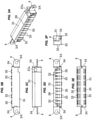
- a connection detecting mechanism of an LC-type optical connector for two cores is mounted, as shown in Figs. 1E, to Figs. 5A and 5B , Fig. 10 , and, Fig. 11 , in each of a plurality of rectangular opening portions which are formed in a lower end side in a longitudinal direction of a thin rectangular optical adapter panel 1 mounted, for example, to a light wiring rack and the like (not shown), such that LC-type optical connector interconnecting adapters 11 (hereinafter abbreviated to optical adapters 11) for two cores for interconnecting a pair of opposing two-core LC-type optical connector plugs 20 (hereinafter, abbreviated to optical plugs 20) are arranged side by side each other in a horizontal direction, and is structured such that a connection detecting device 31 having a light emission display portion 32, for example, an LED pilot lamp and the like for detecting connection in a front face and a switch lever 33 made of resin and provided for detecting connection in both front
- the attaching recess 2 at this time has approximately the same width as a length of the connection detecting device 31, and both right and left side wall surfaces of the connection detecting device 31 are retained in right and left opposing inner edges within the attaching recess 2 by a retention frame portion 2A which is bent into an L-shaped form.
- the switch lever 33 is provided in both the front and rear end sides in the lower face of the connection detecting device 31 in the illustrated example, however, the lever 33 may be installed only in the front side.
- the light emission display portion 32 mentioned later is arranged only at any one of the upper and lower positions without a pair of light emission display portions 32 being arranged in the upper and lower portions.
- connection detecting device 31 when the connection detecting device 31 is not used, a blank panel 40 provided in its surface with a port display label 39 is previously attached to the attaching recess 2 of the optical adapter panel 1 (refer to Fig. 8C ).
- mounting flange portions 4 are provided in both right and left side faces of the connection detecting device 31, and are mounted to the optical wiring rack (not shown) by inserting screws 3 from threaded holes 3A which are formed in the right and left mounting flange portion 4 into threaded holes 1A which are formed in both right and left upper sides of the optical adapter panel 1.
- guide keys 34 which are horizontal in a front-back direction are provided at positions which are separated to a rearward direction of the mounting flange portion 4 in lower sides of both the right and left side surfaces of the connection detecting device 31, and guide grooves 1D for inserting the guide keys 34 from a forward direction of the adapter panel 1 are provided at opposing positions of right and left inner edges in the attaching recess 2 of the optical adapter panel 1 in correspondence thereto.
- it can be mounted to the optical wiring rack (not shown) by inserting the screws 1C into the threaded holes 1B which are formed in the lower sides of both the right and left ends of the optical adapter panel 1.
- downward projections 35 are provided in both front and rear end sides of the lower face of the connection detecting device 31, and hole portions 36 (refer to Fig. 6A and Figs. 7A, 7B and 7D mentioned later) are provided in upper wall sides of opening ends of both the fitting portions of the optical adapter 11 in such a manner as to correspond thereto.
- the optical adapter 11 is positioned in relation to the connection detecting device 31 by moving downward the connection detecting device 31 in a state in which the connection detecting device 31 is locked to the optical adapter panel 1 by the mounting flange portion 4, and fitting the projections 35 to the hole portions 36.
- a communication connector 37 for connecting a communication cable with a relay portion is connected to the connection detecting device 31 (refer to Figs. 1A to 1E and Figs. 2A to 2C ).
- Reference sign 37a in the drawing denotes a connector to which the communication connector 37 is fitted.
- the connection detecting device 31 can be used along, for example, as a built-in battery type, and in this case, the communication connector 37 may be omitted.
- the hole portions 36 may be formed in the connection detecting device 31 side, and the projections 35 may be formed in the optical adapter 11 side.
- the light emission display portions 32 in the front face of the connection detecting device 31 are provided side by side at upper and lower positions in correspondence to the fitting portions A and B in both the front and rear ends of the optical adapter 11. Further, a belt-like port display label 39 having a port number printed as already mentioned is stuck to an upper side of the light emission display portion 32. For information, the port display may be impressed on a front face of the connection detecting device 31.
- a substrate 32B mounting a power control circuit 32A and the like of the light emission display portion 32 thereto is inward installed in an inner portion of the connection detecting device 31, the resin switch lever 33 for detecting connection is arranged in a biased manner in both the front and rear ends of the substrate 32B in a state of being directed to a diagonally forward direction by a compression spring 33D mentioned later, and a leading end of the switch lever 33 is faced to each of rectangular incision-shaped notch concave portions 38 mentioned later in both the front and rear fitting portions of the optical adapter 11.
- the light emission display portion 32 in an upper rear side at this time is electrically connected to the switch lever 33 in the rear side, and the light emission display portion 32 in a lower front side is electrically connected to the switch lever 33 in the front side.
- the light emission display portions 32 such as LED pilot lamps and the like are provided at positions corresponding to the switch levers 33 in the front face lower end side of the device 31, in the front face of the connection detecting device 31, the LED pilot lamp and the like constructing a pair of rear "R" side and front "F” side respectively in an upper side and in a lower side of the connection detecting device, and being capable of changing its display, for example, to a lighting color "green” indicating an on-state and to a lighting color "red” indicating an off-state.
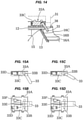
- the switch lever 33 is formed by a resin material, and as shown in Fig. 14 and Fig. 15 , a switch outline portion 33A is installed in an inner bottom portion of the connection detecting device 31, and the switch lever 33 is arranged in one end side of the switch outline portion 33A so as to be swingable by a spindle 33B. Further, a switch unit 33C is provided approximately at the center of an inner portion of the switch outline portion 33A so as to be slidable forward and rearward, and an end portion in the spindle 33B side of the switch lever 33 comes into contact with a front end portion of the switch unit 33C.
- the switch unit 33C is biased to a forward direction (to the switch lever 33 side) by a compression spring 33D which is arranged in a rearward direction, and a leading end of the switch lever 33 is biased with a resilient force of the compression spring 33D in such a manner as to be directed like a downward inclined manner via the switch unit 33C.
- the leading end of the switch lever 33 is arranged within the notch concave portion 38 of the optical adapter 11 in a state of being inclined downward toward a forward direction in relation to the fitting opening portion.
- a male side contact spring 33E protruding approximately like an L-shaped form from a side surface is attached to the switch unit 33C, and the switch unit 33C slides integrally with the male side contact spring 33E.
- a female side contact spring 33F obtained by forming a bifurcated spring leading end into a beak shape (an X-shaped form) is provided in an inner portion of the switch outline portion 33A in correspondence to the male side contact spring 33E.
- the optical adapter 11 is provided in both ends respectively with the fitting portions A and B of the optical plug 20, as shown in Figs. 6A to 6E and Figs. 7A to 7D , in such a manner that optical axes coincide with each other, has in an inner portion thereof a sleeve holder 18 for butt jointing the ferrule leading end portions of each of the optical plugs 20 inserted from the fitting portions A and B in both ends, and is formed in upper wall sides of the opening ends of both the front and rear fitting portions A and B of the optical adapter 11 the rectangular incision-shaped notch concave portions 38.
- the switch lever 33 of the connection detecting device 31 is faced to the notch concave portion 38, the switch lever 33 is pushed up to the switch-on state at the connection finishing time that the optical plug 20 is fully inserted into the fitting portion of the optical adapter 11 instead of being in the half-inserted state, and the "green" lighting color indicating the on-state is displayed on the light emission display portion 32 in the front face.
- the switch lever 33 is kept in the switch-off state in which the switch lever 33 is pushed down, and the light emission display portion 32 in the front face is displayed to the "red” lighting color indicating the off-state (may be turned off the light or may blink).
- the light emission display portion 32 is displayed so as to be viewable the switch lever 33 in correspondence to the on or off state of the switch lever 33.
- the optical adapter 11 is an LC-type optical connector interconnecting adapter for two cores for interconnecting the optical plug 20 having a pair of opposing two-core LC-type optical connector plugs in which a latch lever 28 detachably engaging with the optical adapter 11 is formed on an upper face in a longitudinal direction of a plug from a forward direction toward a rearward direction, as shown in Fig. 10 to Fig. 13 .
- the optical adapter 11 for interconnecting the two-core LC-type optical connectors is provided with the connector housing 12, and is formed into a rectangular tube body having in both ends the fitting portions A and B into which a pair of opposing optical plugs 20 can be inserted mutually from both ends.
- one cylinder 18A constructing a sleeve holder 18 is provided so as to protrude toward one fitting portion A
- the other cylinder 18B is provided so as to protrude toward the other fitting portion B, as shown in Fig. 7C , and Fig. 10 to Fig. 13 .
- Both the cylinders 18A and 18B are formed in such a manner that center axes coincide with each other on an optical axis, and a split sleeve 18C is arranged within both the adjacent cylinders 18A and 18B in an inward inserted state.
- a fixing bracket 19 having a plurality of locking springs for fixing panels each of which is formed by an approximately C-shaped metal frame piece is installed and fixed to each of right and left side walls of the connector housing 12 on the basis of engagement between a locking projection 12A provided in the connector housing 12 side and a locking hole 19A provided in the fixing bracket 19 side.
- an inward C-shaped concave groove portion 16B having a guide ridge 16A in a lower side for guiding insertion of the optical plug 20 is formed in a horizontal direction along a longitudinal direction in upper sides of right and left side walls in the inner portion of the connector housing 12.
- the flared portion 16C having the fitting grooves 16D in the inner end side is formed in the inner portion of the optical adapter 11, and the right and left engagement projections 28A of the latch lever 28 passing through the flared portion 16C and risen up (deformation restored) by the spring force are fitted to the fitting grooves 16D.
- the guide ridge 16A, the concave groove portion 16B and the fitting grooves 16D correspond to a concavo-convex outline shape of the optical plug 20.
- a shutter plate 13 for closing the fitting portion A according to a diagonal arrangement is arranged in the one fitting portion A of the connector housing 12 in such a manner as to be openable and closable in the inner side of the fitting portion A via the spindle 13A. Further, the shutter plate 13 is biased in a closing direction by bringing one end of the leaf spring 14 into contact with an internal bottom surface of the connector housing 12 via the spindle 13A, and bringing the other end into pressure contact with an inside surface of the shutter plate 13.
- a fan-shaped depression portion 15 (refer to Fig.
- the spindle 13A is a so-called pivot of a fan is formed in each of the right and left side walls so as to make the shutter plate 13 be swingable to be openable and closable.
- a depression-shaped clearance portion 13B is formed in the shutter plate 13 in such a manner that a ferrule leading end portion mentioned later does not come into contact with a front face of the shutter plate 13 when the optical plug 20 is inserted from a diagonally upward direction short of the fitting portion A of the connector housing 12.
- the connector housing 12 with the shutter plate 13 is used, however, a normal adapter with no shutter plate 13 may be used.
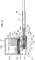
- the LC-type optical plug 20 is provided with a coupling sleeve 21 which is made of plastics having a comparatively high strength, a ferrule 24 which is installed to a ferrule tube 22 and a ferrule frame 23 within the coupling sleeve 21, a spring 25 which is installed to an outer periphery of a rear end portion of the ferrule frame 23, a main body frame 26 which is fitted to the rear end portion of the ferrule frame 23 via the spring 25 and is made of plastics, and a boot 27 which is installed to a rear portion of the main body frame 26, as shown in Fig. 10 to Fig. 13 .
- an outer peripheral surface of the coupling sleeve 21 is provided with a latch lever 28 which has the pair of right and left engagement projections 28A inserted into the inward C-shaped concave groove portion 16B arranged in the upper side within the fitting portions A and B arranged in both ends of the connector housing 12 while engaging therewith, and is integrally provided with the coupling sleeve 21 for engaging with the fitting grooves 16D and disengaging from the fitting grooves 16D.
- the latch lever 28 is extended while inclining so as to be away from the outer surface of the coupling sleeve 21 little by little toward a rear end portion from the leading end portion of the coupling sleeve 21, and the rear end portion protrudes in an inclined manner to an opposite side to the coupling sleeve 21 in such a manner as to come into contact with a release lever 29 which is formed on an outer peripheral surface of the main body frame 27.
- the ferrule 24 of the optical plug 20 installed from the one opening side (for example, the fitting portion A) of the connector housing 12 is fitted to one side of the sleeve holder 18, and the ferrule 24 of the optical plug 20 connected thereto is fitted to the other side of the sleeve holder 18, thereby aligning in a straight line in an axial direction while bringing the leading ends of both the ferrules 24 via the split sleeve 18C which is inward installed over both the cylinders 18a and 18b (refer to Fig. 13 ).
- the LC-type optical connector interconnecting adapter 11 may be constructed by a connector housing 12 for a single core or four or more cores.
- connection detecting device 31 when the connection detecting device 31 is not used, the connection detecting device 31 is mounted to an optical wiring rack and the like (not shown) by inserting the screws 1C into the threaded holes 1B in both the right and left end lower sides of the optical adapter panel 1, as shown in Figs. 8A and 8B . Further, as shown in Fig. 8C , the blank panel 40 additionally provided with the port display label 39 on the surface thereof is previously attached to the threaded hole 1A with the screw 3 in such a manner as to close the attaching recess 2 of the optical adapter panel 1.
- connection detecting device 31 When the connection detecting device 31 is assembled in the optical adapter panel 1, the blank panel 40 is detached so as to open the attaching recess 2 by detaching the screw 3 from the threaded hole 1A, and the connection detecting device 31 is installed within the attaching recess so as to be pinched by the retention frame portion 2A, as shown in Fig. 8D . At this time, as shown in Fig. 8E and Fig. 9A , the guide key 34 of the connection detecting device 31 is inserted into the guide groove 1D in the attaching recess 2 of the optical adapter panel 1 from the forward direction.
- the optical adapter 11 is positioned in relation to the connection detecting device 31 by moving the connection detecting device 31 downward and fitting the projection 35 in the lower face of the connection detecting device 31 to the hole portion 36 of the optical adapter 11 with the mounting flange portion 4 of the connection detecting device 31 coming into contact with the front face of the optical adapter panel 1.
- the thread hole 3A of the mounting flange portion 4 and the threaded hole 1A of the optical adapter panel 1 are in a consistent state.
- the screw 3 is inserted into the threaded hole 3A of the mounting flange portion 4 and a whole of the optical adapter panel 1 is fixed to the optical wiring rack and the like (not shown).
- the shutter plate 13 first closes the fitting end on the one fitting portion A with a resilient force of the leaf spring 14 in an expanding direction, before the optical plug 20 is fitted to the one fitting portion A of the connector housing 12. At this time, a side surface of a movable portion of the shutter plate 13 is locked by a step-like abutment surface of the depression portion 15.
- the closed shutter plate 13 is pushed by an opening edge portion in the leading end of the cylindrical coupling sleeve 21 covering the periphery of the ferrule 24 without bringing the leading end portion of the ferrule 24 of the optical plug 20 into contact with the front face of the shutter plate 13, and the shutter plate 13 is tilted to an inner side of the fitting end against the resilient force of the leaf spring 14.
- the side surface of the movable portion of the shutter plate 13 swings the shutter plate 13 itself in an opening direction (to a lower side) while engaging with the right and left fan-shaped depression portions 15.
- the optical plug 20 itself is inserted in a horizontal state in conjunction with an inserting process on the basis of the existence of the inward C-shaped concave groove portion 16B having the guide ridge 16A in the lower side of the fitting portion A of the connector housing 12.
- the right and left engagement projections 28A of the latch lever 28 are in the process of passing through the flared portion 16C and do not fit to the fitting grooves 16D yet.
- the switch lever 33 of the connection detecting device 31 is not yet pushed up by the latch lever 28, and stays in the switch-off state, and the light emission display portion 32 in the front face displays the "red" lighting color indicating the off state (or may be turned off the light or may be blinked). Therefore, it is possible to securely confirm with the front face view that the optical plug 20 is in the half-inserted state in relation to the fitting portion A of the optical adapter 11.
- connection detecting mechanism according to the present embodiment is applied to an MPO-type optical connector plug with reference to Fig. 16A to Fig. 19B .
- the structure of the connection detecting device 31 and the internal structure (the switch unit 33C, the female side contact spring 33F and the male side contact spring 33E) of the switch outline portion 33A in the inner portion thereof in the present example are the same as those in the example in which the connection detecting device is applied to the LC-type optical connector plug. Therefore, a detailed description thereof will be omitted or simplified.
- an optical plug 50 in the present example is an MPO-type optical connector plug having a tubular coupling 53 which outward inserts a ferrule 52 into a sleeve-shaped housing 51 housing the ferrule 51 in a leading end thereof and is provided so as to be slidable in a movable range which is secured in an axial direction of the housing 51.
- the optical plug 50 is an M-type MPO plug, and is provided with the ferrule 52 which is attached to a leading end of the optical fiber, the sleeve-shaped housing 51 which houses the ferrule 52 in the leading end (the front end), and a spring 55 which is housed within the housing 51 and elastically biases the ferrule 52 to a front side of the connector.
- the optical plug 50 is provided with the tubular coupling 53 which is outward inserted into the housing 51 and is provided so as to be slidable in the movable range which is secured in the axial direction of the housing 51, and a boot 54 which is attached to a rear end portion opposite to the front end where the ferrule 52 is provided in the housing 51.
- reference numeral 57 of the optical plug 50 denotes a guide pin which is fitted to and inserted into a pin hole (not shown) formed in the other side F-type optical plug (not shown).
- the guide pin 57 is inserted into the pin hole of the other side F-type plug so as to butt joint the ferrules 52.
- the M-type optical plug 50 is inserted into the tubular optical adapter 60 from one end portion in the axial direction and fastened, and the F-type optical plug (not shown) corresponding to the other side is inserted into the optical adapter 60 from the other end portion in the axial direction thereof and fastened, thereby butt jointing the ferrules 52 in the front ends of the respective standard optical plugs 50.
- the optical adapter 60 is structured such that a pair of elastic engagement stops 64 are provided in a protruding manner in an inner side of a tubular body 63 in which a connector hole 62 inserting the optical plug 50 thereinto is provided in a penetrating manner, the pair of elastic engagement stops 64 engaging between a pair of front and rear engagement protruding portions 51A and 51B in both sides of the housing 51 of the optical plug 50 so as to freely engage and disengage.
- the elastic engagement stop 64 is an elastic piece which extends into the connector hole 62 from one end of the tubular body 63 in the axial direction toward the other end of the tubular body 63 in the axial direction.
- the elastic engagement stop 64 is structured such as to be engaged with the housing 51 so as to freely engage and disengage by engaging a protruding stop 64A provided in a protruding manner in a leading end of the elastic engagement stop 64 between a pair of front and rear engagement protruding portions 51A and 51B in both sides of the housing 51 of the optical plug 50 (refer to Figs. 19A and 19B ).
- the switch lever 33 for detecting connection is arranged in a state in which the switch lever 33 is directed toward a diagonally rearward direction from the lower face end portion, and the leading end of the switch lever 33 is faced to the rectangular incision-shaped notch concave portion 38 of each of both the front and rear fitting portions of the optical adapter 60.
- the coupling 53 pushes up the switch lever 33 of the connection detecting device 31 to the switch-on state, and the lighting color indicating the on state is displayed on the light emission display portion 32 in the front face (refer to Figs. 19A and 19B ).
- the switch lever 33 is pushed up to the switch-on state, and the "green" lighting color indicating the on state is displayed on the light emission display portion 32 in the front face.
- the switch lever 33 stays in the pushed-down switch-off state, and the "red" lighting color indicating the off state is displayed on the light emission display portion 32 in the front face (may be turned off the light or may be blinked).
- the light emission display portion 32 By viewing the light emission display portion 32 from the front face as mentioned above, it is possible to simultaneously confirm whether or not the optical plugs 50 inserted into the fitting portions in both ends of the optical adapter 60 are in the half-inserted state.
- the leading end of the switch lever 33 is arranged in a state in which the leading end is inclined downward to the rearward direction in relation to the fitting opening portion within the notch concave portion 38 of the optical adapter 60.
- the switch lever 33 of the connection detecting device 31 is not pushed up yet by the coupling 53, and stays in the switch-off state, and the light emission display portion 32 in the front face is in the half-inserted state in which the "red" lighting color indicating the off state stays displaying (may be turned off the light or may be blinked).
- the protruding stop 64A eats into and is locked to a recess between the front and rear engagement protruding portions 51A and 51B at same time that the protruding stop 64A in the inner surface of the leading end of the elastic engagement stop 64 gets over the engagement protruding portion 51A (the catch portion) in the rearward direction.
- the coupling 53 slides forward on the basis of the forward elastic biasing by the spring 56, and the leading end of the coupling 53 pushes up the switch lever 33 of the connection detecting device 31 to the switch-on state, so that the "green" lighting color indicating the on state is displayed in the light emission display portion 32 in the front face.
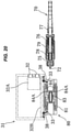
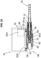
- connection detecting mechanism according to the present embodiment is applied to an MU-type optical connector plug with reference to Fig. 20 to Fig. 23 .
- the structure of the connection detecting device 31 and the internal structure (the switch unit 33C, the female side contact spring 33F and the male side contact spring 33E) and the like of the switch in the inner portion thereof in the present example are the same as those of the example in which the connection detecting device is applied to the LC-type optical connector plug. Therefore, a detailed description thereof will be omitted or simplified.
- the switch outline portion 33A is structured reversely in the front-back direction as shown in Fig. 20 to Fig. 23 and Fig.
- the leading end of the switch lever 33 is arranged within the notch concave portion 38 of the optical adapter 80 in a state in which the leading end is downward inclined toward the rearward direction (the inner side of the fitting portion) in relation to the fitting opening portion, before the insertion of the optical plug 70 into the optical adapter 80.
- the optical plug 70 is an MU-type optical connector plug structured such that a knob 79 is outward installed to an outer side of a plug frame 75 and the plug frame 75 can slide at a desired stroke within the knob 79 in an axial direction.
- the optical plug 70 is structured such that the plug frame formed into a wide quadrangular shape and a ring 76 made of metal are installed in the axial direction, a rubber holder 77 is coupled to a rear end portion of the ring 76 in the axial direction so as to be integrated, and a ferrule 72 having a fiber inserted into and bonded to a center thereof is inward inserted and arranged at the center thereof via a spring 78 in relation to the ring 76.
- the knob 79 is outward installed to an outer side of the plug frame 75, and the plug frame 75 is structured such as to be slidable at the desired stroke within the knob 79 in the axial direction (a lateral direction in the drawing).
- the optical adapter 80 is structured, as shown in Fig. 20 to Fig. 23 , such that a guide tube 83 (having the same structure as the sleeve holder 18 mentioned above) to which the ferrule 72 is fitted is arranged at the center of a housing which is formed into a wide quadrangular tubular shape, a pair of cantilever arm springy locking pieces 84 made of synthetic resin are integrally protruded from inner wall surfaces of the housings 81 at both right and left side positions of the guide tube 83, and locking protruding portions 84A are provided in a protruding manner in inside center portions of the leading ends.
- the knob 79 pushes up the switch lever 33 of the connection detecting device 31 to the switch-on state, and the "green" lighting color indicating the on state is displayed on the light emission display portion 32 in the front face (refer to Fig. 23 ).
- the switch lever 33 stays the switch-off state in which the switch lever 33 is pushed down, and the "red” lighting color indicating the off state is displayed (may be turned off the light or may be blinked) in the light emission display portion 32 in the front face.
- connection detecting mechanism according to the present embodiment is applied to an SC-type optical connector plug with reference to Fig. 24A to Fig. 27B .
- the structure of the connection detecting device 31 and the internal structure (the switch unit 33C, the female side contact spring 33F, the male side contact spring 33E) and the like of the switch outline portion 33A in the inner portion thereof are the same as those of the example in which the connection detecting device 31 is applied to the LC-type optical connector plug. Therefore, a detailed description will be omitted or simplified.
- the switch outline portion 33A is structured reversely in the front-back direction as shown in Fig. 24A to Fig. 27B , and Fig.
- the leading end of the switch lever 33 is arranged within a notch concave portion 38 of an optical adapter 100 in a state in which the leading end is downward inclined toward the rearward direction (the inner side of the fitting portion) in relation to the fitting opening portion, before the insertion of an optical plug 90 into the optical adapter 100.
- the optical plug 90 is an SC-type optical connector plug structured such that a ferrule 93 is inward installed to a plug frame 92 within a knob 91.
- the optical plug 90 is provided with the knob 91, the plug frame 92 which is housed within the knob 91, the ferrule 93 which is housed within the plug frame 92, a spring 94 which is an elastic member for biasing the ferrule 93 in an axial direction, a stopper 95 which is housed within the plug frame 92 and prevents the ferrule 93 from moving in the axial direction, that is, coming away, and a rubber boot 97.
- a guide projection 98 guided and inserted to the notch concave portion 38 formed at the center of an upper face of the fitting portion in the optical adapter 100 along a direction of optical axis is formed at the center of the upper surface of the knob 91.
- the switch lever 33 of the connection detecting device 31 is faced to the notch concave portion 38.
- locking concave portions 99 are formed in right and left side walls of the plug frame 92, and a locking protruding portion 103A in a leading end of the springy locking piece 103 in the optical adapter 100 mentioned later is locked to the locking concave portion 99 at the same time that the ferrule 93 is fitted to a guide tube 102 mentioned later.
- key grooves (not shown) for introducing the locking protruding portion 103A in the leading end of the springy locking piece 103 are formed in right and left side walls of the knob 91 in correspondence to the locking concave portions 99.
- the optical adapter 100 is structured, as shown in Fig. 24B , Fig. 25B , Fig. 26B and Fig. 27B , such that the guide tube 102 (having the same structure as the sleeve holder 19 mentioned above) to which the ferrule 93 is fitted is arranged at the center of the housing 101 which is formed into the wide quadrangular tubular shape, a pair of cantilever arm springy locking pieces 103 made of synthetic resin are integrally protruded from the inner wall surfaces of the housings 101 at both the right and left side positions of the guide tube 102, and the locking protruding portions 103A locked to the locking concave portions 99 of the plug frame 92 via the key groove of the knob 91 are provided in the protruding manner in the inner side of the leading end.
- the switch lever 33 of the connection detecting device 31 faced to the notch concave portion 38 is pulled upward so as to be pushed away by the guide projection 98 to the switch-on state, and the "green" lighting color indicating the on state is displayed in the light emission display portion 32 in the front face (refer to Fig. 27A ).
- the switch lever 33 stays in the pushed-down switch-off state, and the "red" lighting color indicating the off state is displayed in the light emission display portion 32 in the front face (may be turned off the light or may be blinked).
- the switch lever 33 stays in the pushed-down switch-off state, and the "red" lighting color indicating the off state is displayed in the light emission display portion 32 in the front face (may be turned off the light or may be blinked).
- the lighting color of the light emission display portion 32 in the front face is changed between “green” and “red” (including the light turning off or the light blinking) in correspondence to the on or off state of the switch lever 33.
- the color is not limited to them, but a color combination may be used as long as different colors are used.
- connection detecting mechanism according to the LC, MPO, MU or SC-type optical connector device using the optical fiber.
- present invention can be widely utilized as a connection detecting mechanism of the other electric equipment such as an electric plug outlet and a phone wiring connecting modular jack than the optical fiber.
- the invention easily and securely confirm from a front face of an optical adapter whether an optical connector plug is in a half-inserted state, in the optical adapter when being downsized high-density mounted.
Landscapes
- Physics & Mathematics (AREA)
- General Physics & Mathematics (AREA)
- Optics & Photonics (AREA)
- Mechanical Coupling Of Light Guides (AREA)
- Optical Couplings Of Light Guides (AREA)
Description
- The present invention relates to a connection detecting mechanism of an optical connector plug which is interconnected by an optical adapter, for example, at the downsized high-density mounting time.
- Conventionally, there have been a lot of connection detecting mechanisms of optical connector plugs which can securely prevent the optical connector plug from being erroneously disconnected from an optical adapter at the normal fitting time as well as previously avoiding a half-inserted state of the optical connector plug when being fitted to the optical adapter.
- In particular, as shown in patent literature document
JP 4 685 972 B - Further, as shown in patent
literature document JP 4 588 805 B - Further, as shown in patent literature document
JP 6 219 219 B - Further, as shown in patent literature document
JP 6 229 549 B - Patent literature document
US 2018/136410 A1 discloses a connector engagement sensing mechanism. A connector assembly includes an adapter, a housing device, a ferrule assembly, and a sensor. The housing device is received by the adapter and has a bore, a front end, and a rear end opposite the front end. A ferrule of the ferrule assembly is within the bore of the housing device and has a mating end extending beyond the front end of the housing device. The sensor is mounted on the rear end of the housing, the rear end of the ferrule assembly, or on the adapter confronting and spaced apart from the housing device or the ferrule assembly. The sensor is configured for detecting a force applied by the housing device or the ferrule assembly, respectively. An electrical characteristic of the sensor changes to indicate a predetermined force has been applied by the housing device or the ferrule assembly, respectively. - However, in document
JP 4 685 972 B JP 4 588 805 B - Further, in the case of
document JP 4 588 805 B - Further, in document
JP 6 219 219 B - Further, in document
JP 6 229 549 B - Further, the rotary display portions of document
JP 4 685 972 B JP 4 588 805 B JP 6 219 219 B patent literature 4 are individually attached to each of the optical adapters. As a result, it is very troublesome to install the rotary display portion and attach the communication light detector to each of all the optical adapters and it takes a lot of trouble. - Further, in the communication light detector of document
JP 6 219 219 B JP 6 229 549 B - Accordingly, the present invention is made by taking into consideration the conventionally existing various circumstances as mentioned above, and an object of the present invention is to provide a connection detecting mechanism of an optical connector plug in an optical adapter which can be mounted in a downsized high-density manner, in which the connection detecting mechanism of the optical connector plug can resolve the conventional troublesome work of individually attaching the detecting device to the optical adapter by structuring such as to easily confirm visually from a front face side of the optical adapter whether or not the optical connector plug is in a half-inserted state, prevent the poor connection accident from being generated in all the optical adapter, and attach a connection detecting device according to a single configuration so as to be used in common over all the optical adapter which are adjacent in a lateral direction.
- In order to achieve the object mentioned above, according to the present invention, there is provided a connection detecting mechanism according to
claim 1. Advantageous further developments are as set forth in the dependent claims. - The connection detecting device is formed an outer shape thereof into a rectangular housing shape, and is provided in both front and rear ends of the lower face with the switch lever for detecting connection, and the light emission display portion in the front face of the connection detecting device is formed as a pair of light emission display portions in upper and lower positions in correspondence to the fitting portions in both ends of the optical adapter.
- Horizontal guide keys are provided in both right and left side faces of the connection detecting device, a screw attaching flange portion for fixing to the optical adapter panel is provided at a position which is away from the guide keys, and guide grooves for inserting the guide keys from a forward side of the optical adapter panel are formed at opposing positions of right and left inner edges in the attaching recess of the optical adapter panel.
- Downward projections are provided in both front and rear ends of the lower face of the connection detecting device, hole portions are provided in upper wall sides of opening ends in both the fitting portions of the optical adapter, and the projections and the hole portions are formed in such a manner as to position the optical adapter in relation to the connection detecting device by moving downward the connection detecting device in relation to the optical adapter panel in a state in which the connection detecting device is locked by the screw attaching flange portion, and fitting the projections to the hole portions.
- The optical connector plug is an LC-type optical connector plug in which a latch lever detachably engaging with the optical adapter is formed in an upper surface in a longitudinal direction of the optical connector plug from a forward side toward a rearward side, the latch lever pushes up a switch lever of the connection detecting device so as to change from a switch-off state to a switch-on state when the optical connector plug is fully inserted into the fitting portion of the optical adapter instead of being in a half-inserted state, and the optical connector plug is formed in such a manner that a lighting color of the on-state is displayed on a light emission display portion in the front face.
- The optical connector plug is an MPO-type optical connector plug having a tubular coupling which is outward inserted into a sleeve-shaped housing having a ferrule housed in a leading end thereof and is provided slidably in a movable range which is secured in an axial direction of the housing, the coupling pushes up a switch lever of the connection detecting device so as to change from a switch-off state to a switch-on state when the optical connector plug is fully inserted into the fitting portion of the optical adapter instead of being in a half-inserted state, and the optical connector plug is formed in such a manner that a lighting color of the on-state is displayed on a light emission display portion in the front face.
- The optical connector plug is an MU-type optical connector plug structured such that a knob is outward installed to an outer side of a plug frame and the plug frame can slide at a desired stroke in an axial direction within the know, the knob pushes up a switch lever of the connection detecting device so as to change from a switch-off state to a switch-on state when the connector plug is fully inserted into the fitting portion of the optical adapter instead of being in a half-inserted state, and the optical connector plug is formed in such a manner that a lighting color of the on-state is displayed on a light emission display portion in the front face.
- The optical connector plug is an SC-type optical connector plug in which a ferrule is inward installed within a plug frame attached to an inner portion of a knob, a guide projection formed in the center of an upper surface of the knob pushes up a switch lever of the connection detecting device so as to change from a switch-off state to a switch-on state when the optical connector plug is fully inserted into the fitting portion of the optical adapter instead of being in a half-inserted state, and the optical connector plug is formed in such a manner that a lighting color of the on-state is displayed on a light emission display portion in the front face.
- According to the present invention, in the optical adapter which can be mounted in a downsized high-density manner, it is possible to resolve the conventional troublesome work of individually attaching the detecting device to the optical adapter by structuring such as to easily confirm visually from the front face side of the optical adapter whether or not the optical connector plug is in the half-inserted state, prevent the poor connection accident from being generated in all the optical adapter, and attach the connection detecting device according to the single configuration so as to be used in common over all the optical adapter which are adjacent in the lateral direction. As a result, it is possible to construct various plug security systems which are excellent in convenience.
- More specifically, the present invention includes the connection detecting mechanism of
claim 1. - As a result, in the optical adapter which can be mounted in the downsized high-density mounting manner, it is possible to securely view from the front face of the optical adapter whether or not the optical connector plug is in the half-inserted state.
- The connection detecting device is formed the outer shape thereof into the rectangular housing shape, and is provided in both front and rear ends of the lower face with the switch lever for detecting connection, and the light emission display portion in the front face of the connection detecting device is formed as the pair of light emission display portions in the upper and lower positions in correspondence to the fitting portions in both ends of the optical adapter. As a result, it is possible to simultaneously view from the front face of the optical adapter whether or not the optical connector plug inserted into each of the fitting portions in both ends of the optical adapter is in the half-inserted state.
- The optical adapter panel is provided in such a manner as to arrange side by side and mount the plurality of the optical adapters, the attaching recess having approximately the same width as the length of the connection detecting device is provided in the optical adapter panel in such a manner that the connection detecting device is arranged in the upper side of the optical adapter, and the light emission display portions in the front face of the connection detecting device are formed side by side in the upper and lower positions in correspondence to the fitting portions in both ends of each of the optical adapters. As a result, it is possible to simultaneously view whether or not any of the optical connector plugs respectively inserted into the fitting portions in both ends of the optical adapter is in the half-inserted state, by viewing from the front face the light emission display portions which are arranged side by side in the lateral direction in the upper and lower sides of the connection detecting device, and it is possible to prevent the poor connection accident of the optical connector plug from being generated.
- The horizontal guide keys are provided in both the right and left side faces of the connection detecting device, the screw attaching flange portion for fixing to the optical adapter panel is provided at the position which is away from the guide keys, and the guide grooves for inserting the guide keys from the forward side of the optical adapter panel are formed at the opposing positions of the right and left inner edges in the attaching recess of the optical adapter panel. As a result, it is possible to easily position the connection detecting device in the width direction in relation to the optical adapter panel by inserting the guide key into the guide groove, and it is possible to securely attach the connection detecting device to the attaching recess in the horizontal state.
- The downward projections are provided in both the front and rear ends of the lower face of the connection detecting device, the hole portions are provided in the upper wall sides of the opening ends in both the fitting portions of the optical adapter, and the projections and the hole portions are formed in such a manner as to position the optical adapter in relation to the connection detecting device by moving downward the connection detecting device in relation to the optical adapter panel in a state in which the connection detecting device is locked by the screw attaching flange portion, and fitting the projections to the hole portions. As a result, it is possible to securely integrate the connection detecting device and the optical adapter, and it is possible to appropriately arrange the leading end side of the switch lever of the connection detecting device within the notch concave portion of the optical adapter.
- The optical connector plug is the LC-type optical connector plug in which the latch lever detachably engaging with the optical adapter is formed in the upper surface in the longitudinal direction of the optical connector plug from the forward side toward the rearward side, the latch lever pushes up the switch lever of the connection detecting device so as to change from the switch-off state to the switch-on state when the optical connector plug is fully inserted into the fitting portion of the optical adapter instead of being in the half-inserted state, and the optical connector plug is formed in such a manner that the lighting color of the on-state is displayed on the light emission display portion in the front face. As a result, it is possible to simultaneously confirm whether or not the LC-type optical connector plugs each having the single core, two cores or four cores and inserted into the fitting portions in both ends of the optical adapter are in the half-inserted state, by viewing the light emission display portion from the front face, and it is possible to prevent the poor connection accident of the LC-type optical connector plug from being generated. Further, it is possible to easily detect even in a case where the latch lever is broken and the switch lever can not be pushed up.
- The optical connector plug is the MPO-type optical connector plug having the tubular coupling which is outward inserted into the sleeve-shaped housing having the ferrule housed in the leading end thereof and is provided slidably in the movable range which is secured in the axial direction of the housing, the coupling pushes up the switch lever of the connection detecting device so as to change from the switch-off state to the switch-on state when the optical connector plug is fully inserted into the fitting portion of the optical adapter instead of being in the half-inserted state, and the optical connector plug is formed in such a manner that the lighting color of the on-state is displayed on the light emission display portion in the front face. As a result, it is possible to simultaneously confirm whether or not the MPO-type optical connector plugs each inserted into the fitting portions in both ends of the optical adapter are in the half-inserted state, by viewing the light emission display portion from the front face, and it is possible to prevent the poor connection accident of the MPO-type optical connector plug from being generated.
- The optical connector plug is the MU-type optical connector plug structured such that the knob is outward installed to the outer side of the plug frame and the plug frame can slide at the desired stroke in the axial direction within the know, the knob pushes up the switch lever of the connection detecting device so as to change from the switch-off state to the switch-on state when the connector plug is fully inserted into the fitting portion of the optical adapter instead of being in the half-inserted state, and the optical connector plug is formed in such a manner that the lighting color of the on-state is displayed on the light emission display portion in the front face. It is possible to simultaneously confirm whether or not the MU-type optical connector plugs each inserted into the fitting portions in both ends of the optical adapter are in the half-inserted state, by viewing the light emission display portion from the front face, and it is possible to prevent the poor connection accident of the MU-type optical connector plug from being generated.
- The optical connector plug is the SC-type optical connector plug in which the ferrule is inward installed within the plug frame attached to the inner portion of the knob, the guide projection formed in the center of the upper surface of the knob pushes up the switch lever of the connection detecting device so as to change from the switch-off state to the switch-on state when the optical connector plug is fully inserted into the fitting portion of the optical adapter instead of being in the half-inserted state, and the optical connector plug is formed in such a manner that the lighting color of the on-state is displayed on the light emission display portion in the front face. As a result, it is possible to simultaneously confirm whether or not the SC-type optical connector plugs each inserted into the fitting portions in both ends of the optical adapter are in the half-inserted state, by viewing the light emission display portion from the front face, and it is possible to prevent the poor connection accident of the SC-type optical connector plug from being generated.
-
-
Figs. 1A to 1E show a connection detecting mechanism of an optical connector plug according to a mode for carrying out the present invention, in whichFig. 1A is a back elevational view,Fig. 1B is a plan view,Fig. 1C is a front elevational view,Fig. 1D is a bottom elevational view, andFig. 1E is a side elevational view; -
Figs. 2A to 2C show the connection detecting mechanism of the optical connector plug, in whichFig. 2A is a perspective view as seen from a diagonally forward direction,Fig. 2B is a perspective view as seen from a diagonally rearward direction, andFig. 2C is a cross sectional view along a line A-A inFig. 1C ; -
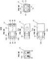
Figs. 3A to 3F show an example of a connection detecting device, in whichFig. 3A is a perspective view as seen from a diagonally forward direction,Fig. 3B is a back elevational view,Fig. 3C is a plan view,Fig. 3D is a front elevational view,Fig. 3E is a bottom elevational view, andFig. 3F is a side elevational view; -
Figs. 4A to 4E show an adapter panel to which an LC-type optical connector interconnecting adapter for two cores is attached, in whichFig. 4A is a back elevational view,Fig. 4B is a plan view,Fig. 4C is a front elevational view,Fig. 4D is a bottom elevational view, andFig. 4E is a side elevational view; -
Figs. 5A and 5B show the adapter panel to which the LC-type optical connector interconnecting adapter for two cores is attached, in whichFig. 5A is a perspective view as seen from a diagonally forward direction, andFig. 5B is a perspective view as seen from a diagonally rearward direction; -
Figs. 6A to 6E show an LC-type optical connector interconnecting adapter for two cores attached to an adapter panel, in whichFig. 6A is a plan view,Fig. 6B is a side elevational view,Fig. 6C is a bottom elevational view,Fig. 6D is a front elevational view, andFig. 6E is a back elevational view; -
Figs. 7A to 7D show the LC-type optical connector interconnecting adapter for two cores attached to the adapter panel, in whichFig. 7A is a perspective view as seen from a diagonally forward direction,Fig. 7B is a perspective view as seen from a diagonally rearward direction,Fig. 7C is a cross sectional view long a line B-B inFig. 6D , andFig. 7D is a cross sectional view along a line C-C inFig. 6D ; -
Figs. 8A to 8H show a procedure for attaching a connection detecting device to an adapter panel to which an LC-type optical connector interconnecting adapter for two cores is attached, in whichFig. 8A is a perspective view of the adapter panel in a state before attachment of the connection detecting device,Fig. 8B is a perspective view in a state in which a screw for fixing the adapter panel is attached,Fig. 8C is a perspective view of the adapter panel in a state in which a brank panel is attached, andFigs. 8D to 8H are perspective views showing a procedure for attaching the connection detecting device to the adapter panel in place of the brank panel; -
Figs. 9A and 9B show a procedure for attaching the connection detecting device to the adapter panel to which the LC-type optical connector interconnecting adapter for two cores is attached, in whichFig. 9A is an enlarged perspective view showing a main part of a state in which a guide key in a side surface of the connection detecting device is inserted into a guide groove from a forward direction of the optical adapter panel, andFig. 9B is an enlarged perspective view showing a main part of a state in which a projection in a lower surface of the connection detecting device is fitted to a hole portion in an upper side of the LC-type optical connector interconnecting adapter for two cores; -
Fig. 10 shows a connection detecting motion and is a cross sectional view of a state in which an LC-type optical connector plug is connected to an LC-type optical connector interconnecting adapter for two cores; -
Fig. 11 shows the connection detecting motion and is a cross sectional view of a state in which the LC-type optical connector plug is inserted and a shutter is half open; -
Fig. 12 shows the connection detecting motion and is a cross sectional view of a state in which the LC-type optical connector plug reaches an optical reference surface position and is in a half-inserted state; -
Fig. 13 shows the connection detecting motion and is a cross sectional view of a state in which the LC-type optical connector plug reaches a fitting completion connection position and a switch lever of the connection detecting device is turned on; -
Fig. 14 is an enlarged cross sectional view of a main part showing a detail of a switch lever mechanism; -
Figs. 15A to 15D show an actuation detail of the switch lever, in whichFig. 15A is a side elevational view when the switch lever is in an off-state,Fig. 15B is a bottom elevational of the same,Fig. 15C is a side elevational view when the switch lever is pushed upward so as to come to an on-state, andFig. 15D is a bottom elevational view of the same; -
Figs. 16A to 16C show a connection detecting motion in a case where an MPO-type optical connector plug is connected to an MPO-type optical connector interconnecting adapter, in whichFig. 16A is a vertical cross sectional view before connection,Fig. 16B is a transverse cross sectional view before connection, andFig. 16C shows a detail of a switch lever structure and is an enlarged cross sectional view of a main part; -
Figs. 17A and 17B show the connection detecting motion, in whichFig. 17A is a vertical cross sectional view of a state in which an elastic engagement stop comes into contact with the MPO-type optical connector plug, andFig. 17B is a transverse cross sectional view; -
Figs. 18A and 18B show the connection detecting motion, in whichFig. 18A is a vertical cross sectional view when the MPO-type optical connector plug reaches the optical reference surface position and comes to a half-inserted state, andFig. 18B is a transverse cross sectional view; -
Figs. 19A to 19B show the connection detecting motion, in whichFig. 19A is a vertical cross sectional view of a state in which the MPO-type optical connector plug reaches a fitting completion connection position and a switch lever of the connection detecting device is turned on, andFig. 19B is a transverse cross sectional view; -
Fig. 20 is a vertical cross sectional view before connection and shows a connection detecting motion in a case where an MU-type optical connector plug is connected to an MU-type optical connector interconnecting adapter; -
Fig. 21 shows the connection detecting motion and is a vertical cross sectional view of a state in which a locking piece comes into contact with the MU-type optical connector plug; -
Fig. 22 shows the connection detecting motion and is a vertical cross sectional view when the MU-type optical connector plug reaches the optical reference surface position and comes to a half-inserted state; -
Fig. 23 shows the connection detecting motion and is a vertical cross sectional view of a state in which the MU-type optical connector plug reaches the fitting completion connection position and the switch lever of the connection detecting device is turned on; -
Figs. 24A and 24B show a connection detecting motion in a case where an SC-type optical connector plug is connected to an SC-type optical connector interconnecting adapter, in whichFig. 24A is a vertical cross sectional view before connection, andFig. 24B is a transverse cross sectional view; -
Figs. 25A and 25B show the connection detecting motion, in whichFig. 25A is a vertical cross sectional view of a state in which a locking piece comes into contact with the SC-type optical connector plug, andFig. 25B is a transverse cross sectional view; -
Figs. 26A and 26B show the connection detecting motion, in whichFig. 26A is a vertical cross sectional view when the SC-type optical connector plug reaches the optical reference surface position and comes to the half-inserted state, andFig. 26B is a transverse cross sectional view; and -
Figs. 27A and 27B show the connection detecting motion, in whichFig. 27A is a vertical cross sectional view of a state in which the SC-type optical connector plug reaches the fitting completion connection position and the switch lever of the connection detecting device is turned on, andFig. 27B is a transverse cross sectional view. - A description will be in detail given below of an embodiment of a connection detecting mechanism of an optical connector plug according to the present invention with reference to the accompanying drawings. In the following description, a description will be sequentially given of respective connection detecting mechanisms of an LC-type optical connector, an MPO-type optical connector, an MU-type optical connector, and an SC-type optical connector. The LC-type optical connector and the like are made for two cores, however, may be made for a single core or four or more cores.
- A connection detecting mechanism of an LC-type optical connector for two cores according to the present embodiment is mounted, as shown in
Figs. 1E, to Figs. 5A and5B ,Fig. 10 , and,Fig. 11 , in each of a plurality of rectangular opening portions which are formed in a lower end side in a longitudinal direction of a thin rectangularoptical adapter panel 1 mounted, for example, to a light wiring rack and the like (not shown), such that LC-type optical connector interconnecting adapters 11 (hereinafter abbreviated to optical adapters 11) for two cores for interconnecting a pair of opposing two-core LC-type optical connector plugs 20 (hereinafter, abbreviated to optical plugs 20) are arranged side by side each other in a horizontal direction, and is structured such that aconnection detecting device 31 having a lightemission display portion 32, for example, an LED pilot lamp and the like for detecting connection in a front face and aswitch lever 33 made of resin and provided for detecting connection in both front and rear ends in a lower face, and formed into a rectangular housing shape is installed to an attachingrecess 2 which is notched into a rectangular shape in an upper end side of theadapter panel 1 in a longitudinal direction in such a manner as to approximately correspond to a transverse width obtained by totalizing the plurality of rectangular opening portions. The attachingrecess 2 at this time has approximately the same width as a length of theconnection detecting device 31, and both right and left side wall surfaces of theconnection detecting device 31 are retained in right and left opposing inner edges within the attachingrecess 2 by aretention frame portion 2A which is bent into an L-shaped form. - Further, the
switch lever 33 is provided in both the front and rear end sides in the lower face of theconnection detecting device 31 in the illustrated example, however, thelever 33 may be installed only in the front side. In this case, the lightemission display portion 32 mentioned later is arranged only at any one of the upper and lower positions without a pair of lightemission display portions 32 being arranged in the upper and lower portions. - For information, when the
connection detecting device 31 is not used, ablank panel 40 provided in its surface with aport display label 39 is previously attached to the attachingrecess 2 of the optical adapter panel 1 (refer toFig. 8C ). - As shown in
Figs. 1A to 5B andFig. 9A , mountingflange portions 4 are provided in both right and left side faces of theconnection detecting device 31, and are mounted to the optical wiring rack (not shown) by insertingscrews 3 from threadedholes 3A which are formed in the right and left mountingflange portion 4 into threadedholes 1A which are formed in both right and left upper sides of theoptical adapter panel 1. Further, guidekeys 34 which are horizontal in a front-back direction are provided at positions which are separated to a rearward direction of the mountingflange portion 4 in lower sides of both the right and left side surfaces of theconnection detecting device 31, and guidegrooves 1D for inserting theguide keys 34 from a forward direction of theadapter panel 1 are provided at opposing positions of right and left inner edges in the attachingrecess 2 of theoptical adapter panel 1 in correspondence thereto. For information, it can be mounted to the optical wiring rack (not shown) by inserting thescrews 1C into the threadedholes 1B which are formed in the lower sides of both the right and left ends of theoptical adapter panel 1. - Further, as shown in
Figs. 3A, 3B, 3D, 3E andFig. 9B ,downward projections 35 are provided in both front and rear end sides of the lower face of theconnection detecting device 31, and hole portions 36 (refer toFig. 6A andFigs. 7A, 7B and 7D mentioned later) are provided in upper wall sides of opening ends of both the fitting portions of theoptical adapter 11 in such a manner as to correspond thereto. Theoptical adapter 11 is positioned in relation to theconnection detecting device 31 by moving downward theconnection detecting device 31 in a state in which theconnection detecting device 31 is locked to theoptical adapter panel 1 by the mountingflange portion 4, and fitting theprojections 35 to thehole portions 36. Acommunication connector 37 for connecting a communication cable with a relay portion (not shown) is connected to the connection detecting device 31 (refer toFigs. 1A to 1E andFigs. 2A to 2C ).Reference sign 37a in the drawing denotes a connector to which thecommunication connector 37 is fitted. For information, theconnection detecting device 31 can be used along, for example, as a built-in battery type, and in this case, thecommunication connector 37 may be omitted. Further, thehole portions 36 may be formed in theconnection detecting device 31 side, and theprojections 35 may be formed in theoptical adapter 11 side. - The light
emission display portions 32 in the front face of theconnection detecting device 31 are provided side by side at upper and lower positions in correspondence to the fitting portions A and B in both the front and rear ends of theoptical adapter 11. Further, a belt-likeport display label 39 having a port number printed as already mentioned is stuck to an upper side of the lightemission display portion 32. For information, the port display may be impressed on a front face of theconnection detecting device 31. Asubstrate 32B mounting apower control circuit 32A and the like of the lightemission display portion 32 thereto is inward installed in an inner portion of theconnection detecting device 31, theresin switch lever 33 for detecting connection is arranged in a biased manner in both the front and rear ends of thesubstrate 32B in a state of being directed to a diagonally forward direction by acompression spring 33D mentioned later, and a leading end of theswitch lever 33 is faced to each of rectangular incision-shaped notchconcave portions 38 mentioned later in both the front and rear fitting portions of theoptical adapter 11. The lightemission display portion 32 in an upper rear side at this time is electrically connected to theswitch lever 33 in the rear side, and the lightemission display portion 32 in a lower front side is electrically connected to theswitch lever 33 in the front side. - As shown in
Figs. 1B, 1C ,Figs. 2A, 2C ,Figs. 3A, 3C ,Figs. 7A to 7D , andFig. 10 to Fig. 13 , the lightemission display portions 32 such as LED pilot lamps and the like are provided at positions corresponding to the switch levers 33 in the front face lower end side of thedevice 31, in the front face of theconnection detecting device 31, the LED pilot lamp and the like constructing a pair of rear "R" side and front "F" side respectively in an upper side and in a lower side of the connection detecting device, and being capable of changing its display, for example, to a lighting color "green" indicating an on-state and to a lighting color "red" indicating an off-state. More specifically, theswitch lever 33 is formed by a resin material, and as shown inFig. 14 and Fig. 15 , aswitch outline portion 33A is installed in an inner bottom portion of theconnection detecting device 31, and theswitch lever 33 is arranged in one end side of theswitch outline portion 33A so as to be swingable by aspindle 33B. Further, aswitch unit 33C is provided approximately at the center of an inner portion of theswitch outline portion 33A so as to be slidable forward and rearward, and an end portion in thespindle 33B side of theswitch lever 33 comes into contact with a front end portion of theswitch unit 33C. - The
switch unit 33C is biased to a forward direction (to theswitch lever 33 side) by acompression spring 33D which is arranged in a rearward direction, and a leading end of theswitch lever 33 is biased with a resilient force of thecompression spring 33D in such a manner as to be directed like a downward inclined manner via theswitch unit 33C. In this case, as shown inFig. 10 to Fig. 13 , before the insertion of theoptical plug 20 into theoptical adapter 11, the leading end of theswitch lever 33 is arranged within the notchconcave portion 38 of theoptical adapter 11 in a state of being inclined downward toward a forward direction in relation to the fitting opening portion. - As shown in
Figs. 15A to 15D , a maleside contact spring 33E protruding approximately like an L-shaped form from a side surface is attached to theswitch unit 33C, and theswitch unit 33C slides integrally with the maleside contact spring 33E. Further, a femaleside contact spring 33F obtained by forming a bifurcated spring leading end into a beak shape (an X-shaped form) is provided in an inner portion of theswitch outline portion 33A in correspondence to the maleside contact spring 33E. When theswitch unit 33C is pushed and moves rearward on the basis of an upward swinging motion of theswitch lever 33 via thespindle 33B, the L-shaped leading end side of the maleside contact spring 33E is pinched and fitted to the beak portion of the femaleside contact spring 33F. As a result, the lightemission display portion 32 comes to a switch-on state. - The
optical adapter 11 is provided in both ends respectively with the fitting portions A and B of theoptical plug 20, as shown inFigs. 6A to 6E andFigs. 7A to 7D , in such a manner that optical axes coincide with each other, has in an inner portion thereof asleeve holder 18 for butt jointing the ferrule leading end portions of each of theoptical plugs 20 inserted from the fitting portions A and B in both ends, and is formed in upper wall sides of the opening ends of both the front and rear fitting portions A and B of theoptical adapter 11 the rectangular incision-shaped notchconcave portions 38. Further, the leading end side of theswitch lever 33 of theconnection detecting device 31 is faced to the notchconcave portion 38, theswitch lever 33 is pushed up to the switch-on state at the connection finishing time that theoptical plug 20 is fully inserted into the fitting portion of theoptical adapter 11 instead of being in the half-inserted state, and the "green" lighting color indicating the on-state is displayed on the lightemission display portion 32 in the front face. In the meantime, in the half-inserted state at the non-connecting state, theswitch lever 33 is kept in the switch-off state in which theswitch lever 33 is pushed down, and the lightemission display portion 32 in the front face is displayed to the "red" lighting color indicating the off-state (may be turned off the light or may blink). As mentioned above, the lightemission display portion 32 is displayed so as to be viewable theswitch lever 33 in correspondence to the on or off state of theswitch lever 33. - In the present embodiment, the
optical adapter 11 is an LC-type optical connector interconnecting adapter for two cores for interconnecting theoptical plug 20 having a pair of opposing two-core LC-type optical connector plugs in which alatch lever 28 detachably engaging with theoptical adapter 11 is formed on an upper face in a longitudinal direction of a plug from a forward direction toward a rearward direction, as shown inFig. 10 to Fig. 13 . When theoptical plug 20 is fully inserted into the fitting portion A of theoptical adapter 11 instead of being in the half-inserted state and is completed its connection, right and leftengagement projections 28A of thelatch lever 28 passing through a flaredportion 16C of theoptical adapter 11 and rising up (deformation restored) are fitted to thefitting grooves 16D as mentioned later. As a result, thelatch lever 28 pushes up theswitch lever 33 of theconnection detecting device 31 to be the switch-on state from the switch-off state, and the lightemission display portion 32 in the front face is displayed into the "green" lighting color indicating the on-state. - In particular, as shown in
Figs. 7A to 7D andFig. 10 to Fig. 13 , theoptical adapter 11 for interconnecting the two-core LC-type optical connectors is provided with theconnector housing 12, and is formed into a rectangular tube body having in both ends the fitting portions A and B into which a pair of opposingoptical plugs 20 can be inserted mutually from both ends. At the center of the inner portion of theconnector housing 12, onecylinder 18A constructing asleeve holder 18 is provided so as to protrude toward one fitting portion A, and theother cylinder 18B is provided so as to protrude toward the other fitting portion B, as shown inFig. 7C , andFig. 10 toFig. 13 . Both thecylinders split sleeve 18C is arranged within both theadjacent cylinders - A fixing
bracket 19 having a plurality of locking springs for fixing panels each of which is formed by an approximately C-shaped metal frame piece is installed and fixed to each of right and left side walls of theconnector housing 12 on the basis of engagement between a lockingprojection 12A provided in theconnector housing 12 side and alocking hole 19A provided in the fixingbracket 19 side. - Further, as shown in
Figs. 7A to 7D , an inward C-shapedconcave groove portion 16B having aguide ridge 16A in a lower side for guiding insertion of theoptical plug 20 is formed in a horizontal direction along a longitudinal direction in upper sides of right and left side walls in the inner portion of theconnector housing 12. The flaredportion 16C having thefitting grooves 16D in the inner end side is formed in the inner portion of theoptical adapter 11, and the right and leftengagement projections 28A of thelatch lever 28 passing through the flaredportion 16C and risen up (deformation restored) by the spring force are fitted to thefitting grooves 16D. Theguide ridge 16A, theconcave groove portion 16B and thefitting grooves 16D correspond to a concavo-convex outline shape of theoptical plug 20. - A
shutter plate 13 for closing the fitting portion A according to a diagonal arrangement is arranged in the one fitting portion A of theconnector housing 12 in such a manner as to be openable and closable in the inner side of the fitting portion A via thespindle 13A. Further, theshutter plate 13 is biased in a closing direction by bringing one end of theleaf spring 14 into contact with an internal bottom surface of theconnector housing 12 via thespindle 13A, and bringing the other end into pressure contact with an inside surface of theshutter plate 13. For information, a fan-shaped depression portion 15 (refer toFig. 7C ) in which thespindle 13A is a so-called pivot of a fan is formed in each of the right and left side walls so as to make theshutter plate 13 be swingable to be openable and closable. Further, a depression-shapedclearance portion 13B is formed in theshutter plate 13 in such a manner that a ferrule leading end portion mentioned later does not come into contact with a front face of theshutter plate 13 when theoptical plug 20 is inserted from a diagonally upward direction short of the fitting portion A of theconnector housing 12. For information, in the present example, theconnector housing 12 with theshutter plate 13 is used, however, a normal adapter with noshutter plate 13 may be used. - The LC-type
optical plug 20 is provided with acoupling sleeve 21 which is made of plastics having a comparatively high strength, aferrule 24 which is installed to aferrule tube 22 and aferrule frame 23 within thecoupling sleeve 21, aspring 25 which is installed to an outer periphery of a rear end portion of theferrule frame 23, amain body frame 26 which is fitted to the rear end portion of theferrule frame 23 via thespring 25 and is made of plastics, and aboot 27 which is installed to a rear portion of themain body frame 26, as shown inFig. 10 to Fig. 13 . - Further, an outer peripheral surface of the
coupling sleeve 21 is provided with alatch lever 28 which has the pair of right and leftengagement projections 28A inserted into the inward C-shapedconcave groove portion 16B arranged in the upper side within the fitting portions A and B arranged in both ends of theconnector housing 12 while engaging therewith, and is integrally provided with thecoupling sleeve 21 for engaging with thefitting grooves 16D and disengaging from thefitting grooves 16D. Thelatch lever 28 is extended while inclining so as to be away from the outer surface of thecoupling sleeve 21 little by little toward a rear end portion from the leading end portion of thecoupling sleeve 21, and the rear end portion protrudes in an inclined manner to an opposite side to thecoupling sleeve 21 in such a manner as to come into contact with arelease lever 29 which is formed on an outer peripheral surface of themain body frame 27. - As mentioned above, the
ferrule 24 of theoptical plug 20 installed from the one opening side (for example, the fitting portion A) of theconnector housing 12 is fitted to one side of thesleeve holder 18, and theferrule 24 of theoptical plug 20 connected thereto is fitted to the other side of thesleeve holder 18, thereby aligning in a straight line in an axial direction while bringing the leading ends of both theferrules 24 via thesplit sleeve 18C which is inward installed over both the cylinders 18a and 18b (refer toFig. 13 ). For information, in place of constructing the LC-type opticalconnector interconnecting adapter 11 by theconnector housing 12 for two cores mentioned above, the LC-type optical connector interconnecting adapter may be constructed by aconnector housing 12 for a single core or four or more cores. - Next, a description will be given of an example of an assembly, a use and a motion of the best mode structured as mentioned above.
- First, when the
connection detecting device 31 is not used, theconnection detecting device 31 is mounted to an optical wiring rack and the like (not shown) by inserting thescrews 1C into the threadedholes 1B in both the right and left end lower sides of theoptical adapter panel 1, as shown inFigs. 8A and 8B . Further, as shown inFig. 8C , theblank panel 40 additionally provided with theport display label 39 on the surface thereof is previously attached to the threadedhole 1A with thescrew 3 in such a manner as to close the attachingrecess 2 of theoptical adapter panel 1. - When the
connection detecting device 31 is assembled in theoptical adapter panel 1, theblank panel 40 is detached so as to open the attachingrecess 2 by detaching thescrew 3 from the threadedhole 1A, and theconnection detecting device 31 is installed within the attaching recess so as to be pinched by theretention frame portion 2A, as shown inFig. 8D . At this time, as shown inFig. 8E andFig. 9A , theguide key 34 of theconnection detecting device 31 is inserted into theguide groove 1D in the attachingrecess 2 of theoptical adapter panel 1 from the forward direction. - Further, as shown in
Fig. 8G andFig. 9B , theoptical adapter 11 is positioned in relation to theconnection detecting device 31 by moving theconnection detecting device 31 downward and fitting theprojection 35 in the lower face of theconnection detecting device 31 to thehole portion 36 of theoptical adapter 11 with the mountingflange portion 4 of theconnection detecting device 31 coming into contact with the front face of theoptical adapter panel 1. At this time, thethread hole 3A of the mountingflange portion 4 and the threadedhole 1A of theoptical adapter panel 1 are in a consistent state. Further, as shown inFig. 8H , thescrew 3 is inserted into the threadedhole 3A of the mountingflange portion 4 and a whole of theoptical adapter panel 1 is fixed to the optical wiring rack and the like (not shown). - Next, as shown in
Fig. 10 , in a case where theoptical plug 20 is used in relation to theoptical adapter 11, theshutter plate 13 first closes the fitting end on the one fitting portion A with a resilient force of theleaf spring 14 in an expanding direction, before theoptical plug 20 is fitted to the one fitting portion A of theconnector housing 12. At this time, a side surface of a movable portion of theshutter plate 13 is locked by a step-like abutment surface of thedepression portion 15. - As shown in
Fig. 11 , theclosed shutter plate 13 is pushed by an opening edge portion in the leading end of thecylindrical coupling sleeve 21 covering the periphery of theferrule 24 without bringing the leading end portion of theferrule 24 of theoptical plug 20 into contact with the front face of theshutter plate 13, and theshutter plate 13 is tilted to an inner side of the fitting end against the resilient force of theleaf spring 14. At this time, the side surface of the movable portion of theshutter plate 13 swings theshutter plate 13 itself in an opening direction (to a lower side) while engaging with the right and left fan-shapeddepression portions 15. - As shown in
Fig. 12 , by further pressing theoptical plug 20 into the fitting portion A of theconnector housing 12, theoptical plug 20 itself is inserted in a horizontal state in conjunction with an inserting process on the basis of the existence of the inward C-shapedconcave groove portion 16B having theguide ridge 16A in the lower side of the fitting portion A of theconnector housing 12. At this time, the right and leftengagement projections 28A of thelatch lever 28 are in the process of passing through the flaredportion 16C and do not fit to thefitting grooves 16D yet. As a result, theswitch lever 33 of theconnection detecting device 31 is not yet pushed up by thelatch lever 28, and stays in the switch-off state, and the lightemission display portion 32 in the front face displays the "red" lighting color indicating the off state (or may be turned off the light or may be blinked). Therefore, it is possible to securely confirm with the front face view that theoptical plug 20 is in the half-inserted state in relation to the fitting portion A of theoptical adapter 11. - As shown in
Fig. 13 , when theoptical plug 20 is fully inserted into the fitting portion A of theoptical adapter 11 instead of being in the half-inserted state and finishes connection, the right and leftengagement projections 28A of thelatch lever 28 passing through the flaredportion 16C of theoptical adapter 11 and rising up (deformation restored) by the spring force fit to thefitting grooves 16D. As a result, thelatch lever 28 pushes up theswitch lever 33 of theconnection detecting device 31 and comes to the switch-on state, and the "green" lighting color indicating the on-state is displayed on the lightemission display portion 32 in the front face. - Next, a description will be given in detail of an example in which the connection detecting mechanism according to the present embodiment is applied to an MPO-type optical connector plug with reference to
Fig. 16A to Fig. 19B . For information, the structure of theconnection detecting device 31 and the internal structure (theswitch unit 33C, the femaleside contact spring 33F and the maleside contact spring 33E) of theswitch outline portion 33A in the inner portion thereof in the present example are the same as those in the example in which the connection detecting device is applied to the LC-type optical connector plug. Therefore, a detailed description thereof will be omitted or simplified. - As shown in
Fig. 16A to Fig. 19B , anoptical plug 50 in the present example is an MPO-type optical connector plug having atubular coupling 53 which outward inserts aferrule 52 into a sleeve-shapedhousing 51 housing theferrule 51 in a leading end thereof and is provided so as to be slidable in a movable range which is secured in an axial direction of thehousing 51. - More specifically, the
optical plug 50 is an M-type MPO plug, and is provided with theferrule 52 which is attached to a leading end of the optical fiber, the sleeve-shapedhousing 51 which houses theferrule 52 in the leading end (the front end), and aspring 55 which is housed within thehousing 51 and elastically biases theferrule 52 to a front side of the connector. Further, theoptical plug 50 is provided with thetubular coupling 53 which is outward inserted into thehousing 51 and is provided so as to be slidable in the movable range which is secured in the axial direction of thehousing 51, and aboot 54 which is attached to a rear end portion opposite to the front end where theferrule 52 is provided in thehousing 51. Accordingly, thecoupling 53 is elastically biased to the forward side bysprings 56 which are arranged on right and left outer wall surfaces of thehousing 51. For information, in the drawing,reference numeral 57 of theoptical plug 50 denotes a guide pin which is fitted to and inserted into a pin hole (not shown) formed in the other side F-type optical plug (not shown). Theguide pin 57 is inserted into the pin hole of the other side F-type plug so as to butt joint theferrules 52. - In the connection between the
optical plugs 50, the M-typeoptical plug 50 is inserted into the tubularoptical adapter 60 from one end portion in the axial direction and fastened, and the F-type optical plug (not shown) corresponding to the other side is inserted into theoptical adapter 60 from the other end portion in the axial direction thereof and fastened, thereby butt jointing theferrules 52 in the front ends of the respective standard optical plugs 50. - The
optical adapter 60 is structured such that a pair of elastic engagement stops 64 are provided in a protruding manner in an inner side of atubular body 63 in which aconnector hole 62 inserting theoptical plug 50 thereinto is provided in a penetrating manner, the pair of elastic engagement stops 64 engaging between a pair of front and rearengagement protruding portions housing 51 of theoptical plug 50 so as to freely engage and disengage. Further, theelastic engagement stop 64 is an elastic piece which extends into theconnector hole 62 from one end of thetubular body 63 in the axial direction toward the other end of thetubular body 63 in the axial direction. Further, theelastic engagement stop 64 is structured such as to be engaged with thehousing 51 so as to freely engage and disengage by engaging aprotruding stop 64A provided in a protruding manner in a leading end of theelastic engagement stop 64 between a pair of front and rearengagement protruding portions housing 51 of the optical plug 50 (refer toFigs. 19A and 19B ). - As shown in
Fig. 16C , since theswitch outline portion 33A of theconnection detecting device 31 is arranged reversely in the front-back direction, theswitch lever 33 for detecting connection is arranged in a state in which theswitch lever 33 is directed toward a diagonally rearward direction from the lower face end portion, and the leading end of theswitch lever 33 is faced to the rectangular incision-shaped notchconcave portion 38 of each of both the front and rear fitting portions of theoptical adapter 60. When theoptical plug 50 is fully inserted into the fitting portion of theoptical adapter 60 in the state in which theoptical plug 50 is not the half insertion state, thecoupling 53 pushes up theswitch lever 33 of theconnection detecting device 31 to the switch-on state, and the lighting color indicating the on state is displayed on the lightemission display portion 32 in the front face (refer toFigs. 19A and 19B ). For example, at the connection finishing time that theoptical plug 50 is fully inserted into the fitting portion of theoptical adapter 60 instead of being in the half-inserted state, theswitch lever 33 is pushed up to the switch-on state, and the "green" lighting color indicating the on state is displayed on the lightemission display portion 32 in the front face. In the meantime, in the half-inserted state at the non-connected time, theswitch lever 33 stays in the pushed-down switch-off state, and the "red" lighting color indicating the off state is displayed on the lightemission display portion 32 in the front face (may be turned off the light or may be blinked). By viewing the lightemission display portion 32 from the front face as mentioned above, it is possible to simultaneously confirm whether or not theoptical plugs 50 inserted into the fitting portions in both ends of theoptical adapter 60 are in the half-inserted state. - As shown in
Figs. 16A and 16B , before the insertion of theoptical plug 50 into theoptical adapter 60, the leading end of theswitch lever 33 is arranged in a state in which the leading end is inclined downward to the rearward direction in relation to the fitting opening portion within the notchconcave portion 38 of theoptical adapter 60. - As shown in
Figs. 17A and 17B , when the protrudingstop 64A in the leading end of theelastic engagement stop 64 comes into contact with theengagement protruding portion 51A in the forward side, theswitch lever 33 of theconnection detecting device 31 is not pushed up yet by thecoupling 53, and stays in the switch-off state, and the lightemission display portion 32 in the front face is in the half-inserted state in which the "red" lighting color indicating the off state stays displaying (may be turned off the light or may be blinked). - As shown in
Figs. 18A and 18B , when theoptical plug 50 reaches an optical reference surface position within theoptical adapter 60, the leading end of thecoupling 53 is pushed by the protrudingstop 64A in the leading end of theelastic engagement stop 64 against the elastic biasing force of thespring 56 to the forward direction of theoptical plug 50 and thecoupling 53 is somewhat retracted rearward, so that theengagement protruding portion 51A (a catch portion) in the front side of thehousing 51 is partly exposed. At this time, the protrudingstop 64A in the inner surface of the leading end of theelastic engagement stop 64 runs on theengagement protruding portion 51A (the catch portion). Even in this state, theswitch lever 33 of theconnection detecting device 31 is not pushed up yet by thecoupling 53, and stays in the switch-off state, and the lightemission display portion 32 in the front face is in the half-inserted state in which the "red" lighting color indicating the off state stays displaying (may be turned off the light or may be blinked). - As shown in
Figs. 19A and 19B , at the fitting completion position, the protruding stop 64A eats into and is locked to a recess between the front and rearengagement protruding portions stop 64A in the inner surface of the leading end of theelastic engagement stop 64 gets over theengagement protruding portion 51A (the catch portion) in the rearward direction. At the same time, thecoupling 53 slides forward on the basis of the forward elastic biasing by thespring 56, and the leading end of thecoupling 53 pushes up theswitch lever 33 of theconnection detecting device 31 to the switch-on state, so that the "green" lighting color indicating the on state is displayed in the lightemission display portion 32 in the front face. As a result, it is possible to securely confirm with the front face view that theoptical plug 50 is not in the half-inserted state in relation to theconnector hole 62 of theoptical adapter 60. - Next, a description will be given in detail of an example in which the connection detecting mechanism according to the present embodiment is applied to an MU-type optical connector plug with reference to
Fig. 20 to Fig. 23 . For information, the structure of theconnection detecting device 31 and the internal structure (theswitch unit 33C, the femaleside contact spring 33F and the maleside contact spring 33E) and the like of the switch in the inner portion thereof in the present example are the same as those of the example in which the connection detecting device is applied to the LC-type optical connector plug. Therefore, a detailed description thereof will be omitted or simplified. In this regard, theswitch outline portion 33A is structured reversely in the front-back direction as shown inFig. 20 to Fig. 23 andFig. 16C , and the leading end of theswitch lever 33 is arranged within the notchconcave portion 38 of theoptical adapter 80 in a state in which the leading end is downward inclined toward the rearward direction (the inner side of the fitting portion) in relation to the fitting opening portion, before the insertion of theoptical plug 70 into theoptical adapter 80. - Accordingly, the
optical plug 70 is an MU-type optical connector plug structured such that aknob 79 is outward installed to an outer side of aplug frame 75 and theplug frame 75 can slide at a desired stroke within theknob 79 in an axial direction. - More specifically, the
optical plug 70 is structured such that the plug frame formed into a wide quadrangular shape and aring 76 made of metal are installed in the axial direction, arubber holder 77 is coupled to a rear end portion of thering 76 in the axial direction so as to be integrated, and aferrule 72 having a fiber inserted into and bonded to a center thereof is inward inserted and arranged at the center thereof via aspring 78 in relation to thering 76. Further, theknob 79 is outward installed to an outer side of theplug frame 75, and theplug frame 75 is structured such as to be slidable at the desired stroke within theknob 79 in the axial direction (a lateral direction in the drawing). - Further, the
optical adapter 80 is structured, as shown inFig. 20 to Fig. 23 , such that a guide tube 83 (having the same structure as thesleeve holder 18 mentioned above) to which theferrule 72 is fitted is arranged at the center of a housing which is formed into a wide quadrangular tubular shape, a pair of cantilever armspringy locking pieces 84 made of synthetic resin are integrally protruded from inner wall surfaces of thehousings 81 at both right and left side positions of theguide tube 83, and lockingprotruding portions 84A are provided in a protruding manner in inside center portions of the leading ends. - Further, when the
optical plug 70 is fully inserted into theoptical adapter 80 instead of being in the half-inserted state, and the connection is finished, theknob 79 pushes up theswitch lever 33 of theconnection detecting device 31 to the switch-on state, and the "green" lighting color indicating the on state is displayed on the lightemission display portion 32 in the front face (refer toFig. 23 ). In the meantime, in the half-inserted state at the non-connected time, theswitch lever 33 stays the switch-off state in which theswitch lever 33 is pushed down, and the "red" lighting color indicating the off state is displayed (may be turned off the light or may be blinked) in the lightemission display portion 32 in the front face. As a result, it is possible to securely confirm with the front face view that theoptical plug 70 is not in the half-inserted state in relation to theguide tube 83 at the center of thehousing 81 of theoptical adapter 80. - Next, a description will be given in detail of an example in which the connection detecting mechanism according to the present embodiment is applied to an SC-type optical connector plug with reference to
Fig. 24A to Fig. 27B . For information, the structure of theconnection detecting device 31 and the internal structure (theswitch unit 33C, the femaleside contact spring 33F, the maleside contact spring 33E) and the like of theswitch outline portion 33A in the inner portion thereof are the same as those of the example in which theconnection detecting device 31 is applied to the LC-type optical connector plug. Therefore, a detailed description will be omitted or simplified. In this regard, since theswitch outline portion 33A is structured reversely in the front-back direction as shown inFig. 24A to Fig. 27B , andFig. 16C , the leading end of theswitch lever 33 is arranged within a notchconcave portion 38 of anoptical adapter 100 in a state in which the leading end is downward inclined toward the rearward direction (the inner side of the fitting portion) in relation to the fitting opening portion, before the insertion of anoptical plug 90 into theoptical adapter 100. - The
optical plug 90 is an SC-type optical connector plug structured such that aferrule 93 is inward installed to aplug frame 92 within aknob 91. - More specifically, as shown in
Figs. 24A and 24B toFigs. 27A and 27B , theoptical plug 90 is provided with theknob 91, theplug frame 92 which is housed within theknob 91, theferrule 93 which is housed within theplug frame 92, aspring 94 which is an elastic member for biasing theferrule 93 in an axial direction, astopper 95 which is housed within theplug frame 92 and prevents theferrule 93 from moving in the axial direction, that is, coming away, and arubber boot 97. Further, aguide projection 98 guided and inserted to the notchconcave portion 38 formed at the center of an upper face of the fitting portion in theoptical adapter 100 along a direction of optical axis is formed at the center of the upper surface of theknob 91. Theswitch lever 33 of theconnection detecting device 31 is faced to the notchconcave portion 38. Further, lockingconcave portions 99 are formed in right and left side walls of theplug frame 92, and alocking protruding portion 103A in a leading end of thespringy locking piece 103 in theoptical adapter 100 mentioned later is locked to the lockingconcave portion 99 at the same time that theferrule 93 is fitted to aguide tube 102 mentioned later. For information, key grooves (not shown) for introducing thelocking protruding portion 103A in the leading end of thespringy locking piece 103 are formed in right and left side walls of theknob 91 in correspondence to the lockingconcave portions 99. - The
optical adapter 100 is structured, as shown inFig. 24B ,Fig. 25B ,Fig. 26B andFig. 27B , such that the guide tube 102 (having the same structure as thesleeve holder 19 mentioned above) to which theferrule 93 is fitted is arranged at the center of thehousing 101 which is formed into the wide quadrangular tubular shape, a pair of cantilever armspringy locking pieces 103 made of synthetic resin are integrally protruded from the inner wall surfaces of thehousings 101 at both the right and left side positions of theguide tube 102, and thelocking protruding portions 103A locked to the lockingconcave portions 99 of theplug frame 92 via the key groove of theknob 91 are provided in the protruding manner in the inner side of the leading end. - Further, when the
optical plug 90 is fully inserted into the fitting portion of theoptical adapter 100 instead of being in the half-inserted state, that is, when theguide projection 98 in the upper wall of theknob 91 is fully inserted into the internal depth portion of the notchconcave portion 38 at the same time that theferrule 93 is fitted to theguide tube 102, theswitch lever 33 of theconnection detecting device 31 faced to the notchconcave portion 38 is pulled upward so as to be pushed away by theguide projection 98 to the switch-on state, and the "green" lighting color indicating the on state is displayed in the lightemission display portion 32 in the front face (refer toFig. 27A ). In the meantime, in the half-inserted state at the non-connected time, theswitch lever 33 stays in the pushed-down switch-off state, and the "red" lighting color indicating the off state is displayed in the lightemission display portion 32 in the front face (may be turned off the light or may be blinked). As a result, it is possible to securely confirm with the front face view that theoptical plug 90 is fully inserted to the fitting portion of theoptical adapter 100 or in the half-inserted state. For information, since the structure of theoptical adapter 100 is approximately the same as the case of theoptical adapter 100 according to the MPO-type optical connector adapter mentioned above, a detailed description thereof will be omitted. - In addition, in this connection, in each of the examples mentioned above, the lighting color of the light
emission display portion 32 in the front face is changed between "green" and "red" (including the light turning off or the light blinking) in correspondence to the on or off state of theswitch lever 33. However, the color is not limited to them, but a color combination may be used as long as different colors are used. - The description is given of the connection detecting mechanism according to the LC, MPO, MU or SC-type optical connector device using the optical fiber. However, the present invention can be widely utilized as a connection detecting mechanism of the other electric equipment such as an electric plug outlet and a phone wiring connecting modular jack than the optical fiber.
-
- A, B:
- fitting portions
- 1:
- optical adapter panel
- 1A:
- threaded hole
- 1B:
- threaded hole
- 1c:
- screw
- 1D:
- guide groove
- 2:
- attaching recess
- 2A:
- retention frame portion
- 3:
- screw
- 3A:
- threaded hole
- 4:
- mounting flange portion
- 11:
- optical adapter (LC-type optical connector adapter for two cores)
- 12:
- connector housing
- 12A:
- locking projection
- 13:
- shutter plate
- 13A:
- spindle
- 13B:
- clearance portion
- 14:
- leaf spring
- 15:
- depression portion
- 16A:
- guide ridge
- 16B:
- concave groove portion
- 16C:
- flared portion
- 16D:
- fitting groove
- 18:
- sleeve holder
- 18A, 18B:
- cylinders
- 18C:
- split sleeve
- 19:
- fixing bracket
- 19A:
- locking hole
- 20:
- optical plug (LC-type optical connector plug for two cores)
- 21:
- coupling sleeve
- 22:
- tube for ferrule
- 23:
- ferrule frame
- 24:
- ferrule
- 25:
- spring
- 26:
- main body frame
- 27:
- boot
- 28:
- latch lever
- 28A:
- engagement projection
- 29:
- release lever
- 31:
- connection detecting device
- 32:
- light emission display portion
- 32A:
- power supply control circuit
- 32B:
- substrate
- 33:
- switch lever
- 33A:
- switch outline portion
- 33B:
- spindle
- 33C:
- switch unit
- 33D:
- compression spring
- 33E:
- male side contact spring
- 33F:
- female side contact spring
- 34:
- guide key
- 35:
- projection
- 36:
- hole portion
- 37:
- communication connector
- 37a:
- connector
- 38:
- notch concave portion
- 39:
- port display label
- 40:
- blank panel
- 50:
- optical plug (MPO-type optical connector plug)
- 51:
- housing
- 51A, 51B:
- engagement protruding portions
- 52:
- ferrule
- 53:
- coupling
- 54:
- boot
- 55, 56:
- springs
- 57:
- guide pin
- 60:
- optical adapter (MPO-type optical connector adapter)
- 62:
- connector hole
- 63:
- tubular body
- 64:
- elastic engagement stop
- 64A:
- protruding stop
- 70:
- optical plug (MU-type optical connector plug)
- 72:
- ferrule
- 75:
- plug frame
- 76:
- ring
- 77:
- rubber holder
- 78:
- spring
- 79:
- knob
- 80:
- optical adapter (MU-type optical connector adapter)
- 81:
- housing
- 83:
- guide tube
- 84:
- springy locking piece
- 84A:
- locking protruding portion
- 90:
- optical plug (SC-type optical connector plug)
- 91:
- knob
- 92:
- plug frame
- 93:
- ferrule
- 94:
- spring
- 95:
- stopper
- 97:
- rubber boot
- 98:
- guide projection
- 99:
- locking concave portion
- 100:
- optical adapter (SC-type optical connector adapter)
- 101:
- housing
- 102:
- guide tube
- 103:
- springy locking piece
- 103A:
- locking protruding portion
- The invention easily and securely confirm from a front face of an optical adapter whether an optical connector plug is in a half-inserted state, in the optical adapter when being downsized high-density mounted.
Claims (8)
- A connection detecting mechanism of an optical connector plug (20) comprising: a connector plug (20);a connection detecting device (31) which is provided in a front face thereof comprisinga light emission display portion (32) for detecting connection and in a lower face further comprisinga switch lever (33) for detecting connection; andan optical adapter (11) which is provided in both ends with fitting portions of the optical connector plug (20) so that optical axes coincide with each other, for butt joining in an inner portion thereof ferrule leading end portions of the optical connector plug (20) inserted from the fitting portions in both ends,wherein the switch lever (33) in the lower face of the connection detecting device (31) faces in a leading end thereof to a notch concave portion (38) which is formed in an upper wall side of an opening end of the fitting portion in the optical adapter (11),wherein the switch lever (33) is pushed up from a switch-off state to a switch-on state in which a lighting color of the on-state is displayed on the light emission display portion (32) in the front face, when an optical connector plug (20) is fully inserted to the fitting portion of the optical adapter (11) instead of being in a half-inserted state, andwherein an optical adapter panel (1) is provided in such a manner as to arrange side by side and mount a plurality of the optical adapters (11), an attaching recess (2) having approximately the same width as a length of the connection detecting device (31) is provided in the optical adapter panel (1) in such a manner that the connection detecting device (31) is arranged in an upper side of the optical adapter (11), and the light emission display portions (32) in the front face of the connection detecting device (31) are formed side by side in the upper and lower positions in correspondence to the fitting portions in both ends of each of the optical adapters (11).
- The connection detecting mechanism of the optical connector plug (20) according to claim 1, wherein an outer shape of the connection detection device (31) is formed into a rectangular housing shape, and the connection detection device (31) is provided in both front and rear ends of the lower face with the switch lever (33) for detecting connection, and the light emission display portion (32) in the front face of the connection detecting device (31) is formed as a pair of light emission display portions (32) in upper and lower positions in correspondence to the fitting portions in both ends of the optical adapter (11).
- The connection detecting mechanism of the optical connector plug (20) according to claim 1 or 2, wherein horizontal guide keys (34) are provided in both right and left side faces of the connection detecting device (31), a screw attaching flange portion (4) for fixing to the optical adapter panel (1) is provided at a position which is away from the guide keys (34), and guide grooves (1D) for inserting the guide keys (34) from a forward side of the optical adapter panel (1) are formed at opposing positions of right and left inner edges in the attaching recess (2) of the optical adapter panel (11).
- The connection detecting mechanism of the optical connector plug (20) according to any of claims 1 to 3, wherein downward projections (35) are provided in both front and rear ends of the lower face of the connection detecting device (31), hole portions (36) are provided in upper wall sides of opening ends in both the fitting portions of the optical adapter (11), and the projections (35) and the hole portions (36) are formed in such a manner as to position the optical adapter (11) in relation to the connection detecting device (31) by moving downward the connection detecting device (31) in relation to the optical adapter panel (1) in a state in which the connection detecting device (31) is locked by a screw attaching flange portion (4), and fitting the projections (35) to the hole portions (36).
- The connection detecting mechanism of the optical connector plug (20) according to any one of claims 1 to 4, wherein the optical connector plug (20) is an LC-type optical connector plug in which a latch lever (28) detachably engaging with the optical adapter (11) is formed in an upper surface in a longitudinal direction of the optical connector plug (20) from a forward side toward a rearward side, the latch lever (28) pushes up a switch lever (33) of the connection detecting device (31) so as to change from a switch-off state to a switch-on state when the optical connector plug (20) is fully inserted into the fitting portion of the optical adapter (11) instead of being in a half-inserted state, and the optical connector plug (20) is formed in such a manner that a lighting color of the on-state is displayed on a light emission display portion (32) in the front face.
- The connection detecting mechanism of the optical connector plug according to any one of claims 1 to 4, wherein the optical connector plug is an MPO-type optical connector plug (50) having a tubular coupling (53) which is outward inserted into a sleeve-shaped housing (51) having a ferrule (52) housed in a leading end thereof and is provided slidably in a movable range which is secured in an axial direction of the housing (51), the coupling (53) pushes up a switch lever (33) of the connection detecting device (31) so as to change from a switch-off state to a switch-on state when the optical connector plug (50) is fully inserted into the fitting portion of the optical adapter (60) instead of being in a half-inserted state, and the optical connector plug (50) is formed in such a manner that a lighting color of the on-state is displayed on a light emission display portion (32) in the front face.
- The connection detecting mechanism of the optical connector plug according to any one of claims 1 to 4, wherein the optical connector plug is an MU-type optical connector plug (70) structured such that a knob (79) is outward installed to an outer side of a plug frame (75) and the plug frame (75) can slide at a desired stroke in an axial direction within the knob (79), the knob (79) pushes up a switch lever (33) of the connection detecting device (31) so as to change from a switch-off state to a switch-on state when the connector plug (70) is fully inserted into the fitting portion of the optical adapter (80) instead of being in a half-inserted state, and the optical connector plug (70) is formed in such a manner that a lighting color of the on-state is displayed on a light emission display portion (32) in the front face.
- The connection detecting mechanism of the optical connector plug according to any one of claims 1 to 4, wherein the optical connector plug is an SC-type optical connector plug (90) in which a ferrule (93) is inward installed within a plug frame (92) attached to an inner portion of a knob (91), a guide projection (98) formed in the center of an upper surface of the knob (91) pushes up a switch lever (33) of the connection detecting device (31) so as to change from a switch-off state to a switch-on state when the optical connector plug (90) is fully inserted into the fitting portion of the optical adapter (100) instead of being in a half-inserted state, and the optical connector plug is formed in such a manner that a lighting color of the on-state is displayed on a light emission display portion (32) in the front face.
Applications Claiming Priority (1)
| Application Number | Priority Date | Filing Date | Title |
|---|---|---|---|
| JP2018172334A JP7084263B2 (en) | 2018-09-14 | 2018-09-14 | Optical connector plug connection detection mechanism |
Publications (2)
| Publication Number | Publication Date |
|---|---|
| EP3623853A1 EP3623853A1 (en) | 2020-03-18 |
| EP3623853B1 true EP3623853B1 (en) | 2022-01-19 |
Family
ID=67659450
Family Applications (1)
| Application Number | Title | Priority Date | Filing Date |
|---|---|---|---|
| EP19192536.1A Not-in-force EP3623853B1 (en) | 2018-09-14 | 2019-08-20 | Connection detecting mechanism of optical connector plug |
Country Status (5)
| Country | Link |
|---|---|
| US (1) | US10983287B2 (en) |
| EP (1) | EP3623853B1 (en) |
| JP (1) | JP7084263B2 (en) |
| CN (1) | CN110908041B (en) |
| ES (1) | ES2906067T3 (en) |
Families Citing this family (4)
| Publication number | Priority date | Publication date | Assignee | Title |
|---|---|---|---|---|
| FR3100619A1 (en) * | 2019-09-05 | 2021-03-12 | Souriau | Assembly for the assembly of optical fibers with at least two pairs of MPO contacts |
| JP2022071743A (en) * | 2020-10-28 | 2022-05-16 | パナソニックIpマネジメント株式会社 | Light source device, detection unit, optical system, endoscope, and industrial microscope |
| WO2022226406A1 (en) | 2021-04-23 | 2022-10-27 | Commscope Technologies Llc | Panel system with managed connectivity |
| US11391894B1 (en) | 2021-11-11 | 2022-07-19 | Frontier Communications Holdings, Llc | Passive optical couplers having passive optical activity indicators and methods of operating the same |
Citations (1)
| Publication number | Priority date | Publication date | Assignee | Title |
|---|---|---|---|---|
| US20140219614A1 (en) * | 2013-02-05 | 2014-08-07 | Tyco Electronics Uk Ltd. | Optical assemblies with managed connectivity |
Family Cites Families (38)
| Publication number | Priority date | Publication date | Assignee | Title |
|---|---|---|---|---|
| JPS5721927A (en) | 1980-07-15 | 1982-02-04 | Nippon Paint Co Ltd | High-molecular emulsifier |
| US4496213A (en) * | 1982-10-29 | 1985-01-29 | International Telephone And Telegraph Corporation | Audible indicator for a connector |
| JPS59137568A (en) | 1983-01-21 | 1984-08-07 | 東レ株式会社 | Production of laminated fiber sheet article |
| JP2585665Y2 (en) * | 1992-09-21 | 1998-11-25 | 日本電信電話株式会社 | SC type optical connector |
| JP2711985B2 (en) * | 1993-10-04 | 1998-02-10 | 日本航空電子工業株式会社 | Connector unit and connector unit module |
| US6375362B1 (en) * | 1999-05-04 | 2002-04-23 | Siemens Aktiengesellschaft | Optical plug-type connection |
| US6588938B1 (en) * | 2000-10-18 | 2003-07-08 | Fitel Usa Corp. | Optical/electrical plug connector |
| US6511231B2 (en) * | 2000-12-27 | 2003-01-28 | Fitel Usa Corp. | Optical connector receptacle having switching capability |
| US6652155B2 (en) * | 2001-06-21 | 2003-11-25 | Fitel Usa Corp. | Optical connector plug |
| JP3745728B2 (en) * | 2002-11-15 | 2006-02-15 | 東京通信機工業株式会社 | Adapter for memory function connector |
| JP2005235615A (en) * | 2004-02-20 | 2005-09-02 | Hitachi Maxell Ltd | Adapter panel, electronic device, and cable connector recognition system |
| US7046899B2 (en) * | 2004-03-02 | 2006-05-16 | Furukawa Electric North America, Inc. | Universal apparatus for incorporating intelligence into an optical fiber distribution frame |
| JP4927028B2 (en) * | 2008-05-15 | 2012-05-09 | 日立電線株式会社 | Communication light detector |
| CN102106157B (en) * | 2008-07-02 | 2014-08-06 | 瑞特技术有限公司 | System and method for monitoring physical layer connectivity |
| WO2010042591A1 (en) * | 2008-10-07 | 2010-04-15 | Molex Incorporated | Improved patch panel assembly for use with data networks |
| US8588050B2 (en) * | 2008-11-12 | 2013-11-19 | Panduit Corp. | Intelligent patching system |
| ES2731679T3 (en) * | 2010-02-12 | 2019-11-18 | Commscope Technologies Llc | Communications connection system |
| WO2011100616A2 (en) * | 2010-02-12 | 2011-08-18 | Adc Telecommunications, Inc. | Communications bladed panel systems |
| US8406597B2 (en) * | 2010-02-16 | 2013-03-26 | Commscope, Inc. Of North Carolina | Intelligent fiber optic adapter mounting structures that receive and correctly position multiple types of fiber optic adapters and related adapter collars and bulkheads |
| US8571376B2 (en) * | 2010-02-24 | 2013-10-29 | Qwest Communications International Inc. | Optical cable connector |
| JP4588805B1 (en) | 2010-06-14 | 2010-12-01 | 株式会社アドバンスト・ケーブル・システムズ | Optical adapter for connecting optical connectors |
| JP4685972B1 (en) | 2010-10-12 | 2011-05-18 | 株式会社アドバンスト・ケーブル・システムズ | Optical adapter for connecting optical connectors |
| US9380358B2 (en) * | 2011-09-26 | 2016-06-28 | Panduit Corp. | RFID patch cord identification and signaling |
| US9063298B2 (en) * | 2012-05-18 | 2015-06-23 | Tyco Electronics Corporation | Connectors and adapters with auto-latching features |
| EP3059623B1 (en) * | 2012-07-11 | 2021-09-01 | CommScope Connectivity UK Limited | Rfid-enabled optical adapter for use with a patch panel |
| US9075205B2 (en) * | 2012-07-11 | 2015-07-07 | Tyco Electronics Corporation | Connectors and adapters with auto-latching features |
| CN102944921B (en) * | 2012-12-11 | 2017-06-13 | 南京昊风新能源科技合伙企业(有限合伙) | The optical transceiver module of optical fiber can quickly be connected |
| US9423570B2 (en) * | 2013-02-05 | 2016-08-23 | Commscope Technologies Llc | Optical assemblies with managed connectivity |
| US20150060539A1 (en) * | 2013-09-04 | 2015-03-05 | Adc Telecommunications, Inc. | Telecommunications systems with managed connectivity |
| JP6229549B2 (en) * | 2014-03-04 | 2017-11-15 | 日立金属株式会社 | Communication light detector |
| EP3123220A4 (en) * | 2014-03-26 | 2017-11-01 | TE Connectivity Corporation | Optical adapter module with managed connectivity |
| JP6219219B2 (en) | 2014-04-04 | 2017-10-25 | 日立金属株式会社 | Duplex LC communication light detection structure |
| US10690862B2 (en) * | 2015-07-01 | 2020-06-23 | Go!Foton Holdings, Inc. | Connector engagement sensing mechanism |
| US10359578B2 (en) * | 2015-07-01 | 2019-07-23 | Go!Foton Holdings, Inc. | Connector engagement sensing mechanism |
| JP6676965B2 (en) * | 2015-12-25 | 2020-04-08 | 日立金属株式会社 | Communication light visualization patch panel |
| JP6690231B2 (en) * | 2015-12-25 | 2020-04-28 | 日立金属株式会社 | Communication light visualization patch panel |
| US20180006726A1 (en) * | 2016-07-01 | 2018-01-04 | Electronics And Telecommunications Research Institute | Optical distribution network including optical cable and optical node, and operating method thereof |
| EP3655883A4 (en) * | 2017-07-19 | 2020-12-30 | Fiber Mountain, Inc. | FIBERGLASS CONNECTOR ARRANGEMENT |
-
2018
- 2018-09-14 JP JP2018172334A patent/JP7084263B2/en active Active
-
2019
- 2019-08-13 US US16/538,874 patent/US10983287B2/en active Active
- 2019-08-20 EP EP19192536.1A patent/EP3623853B1/en not_active Not-in-force
- 2019-08-20 ES ES19192536T patent/ES2906067T3/en active Active
- 2019-09-04 CN CN201910831397.1A patent/CN110908041B/en not_active Expired - Fee Related
Patent Citations (1)
| Publication number | Priority date | Publication date | Assignee | Title |
|---|---|---|---|---|
| US20140219614A1 (en) * | 2013-02-05 | 2014-08-07 | Tyco Electronics Uk Ltd. | Optical assemblies with managed connectivity |
Also Published As
| Publication number | Publication date |
|---|---|
| US20200088949A1 (en) | 2020-03-19 |
| EP3623853A1 (en) | 2020-03-18 |
| US10983287B2 (en) | 2021-04-20 |
| CN110908041B (en) | 2022-08-02 |
| JP2020046456A (en) | 2020-03-26 |
| CN110908041A (en) | 2020-03-24 |
| ES2906067T3 (en) | 2022-04-13 |
| JP7084263B2 (en) | 2022-06-14 |
Similar Documents
| Publication | Publication Date | Title |
|---|---|---|
| US10983287B2 (en) | Connection detecting mechanism of optical connector plug | |
| US8376628B2 (en) | Optical connector plug | |
| CA3020696C (en) | Rotatable fiber optic connector | |
| US9971102B2 (en) | Fibre optic cable assembly | |
| US10156683B2 (en) | Polarity identification for polarity reversing duplex unibody connectors | |
| JP6363784B1 (en) | Optical connector plug and duplex optical connector plug | |
| CN102099720B (en) | Optical adapter | |
| US20100266245A1 (en) | Fiber termination for fiber optic connection system | |
| US20210055482A1 (en) | Optical fiber adapter | |
| KR20180016642A (en) | Optical communication connector | |
| TWI699933B (en) | Connector system | |
| US20250060541A1 (en) | Optical Communications Connectors | |
| WO2017130588A1 (en) | Optical connector and optical connector system | |
| WO2008029850A1 (en) | Optical connector | |
| JP4886743B2 (en) | Socket for adapter and module | |
| KR101408429B1 (en) | Double plug-in connector for optical waveguides | |
| JP2016080763A (en) | Plug with built-in connector | |
| US20070190841A1 (en) | Optical connector system | |
| AU2015312155A1 (en) | Optical adaptor for mounting to a receptacle to optically couple connectorized optical cables | |
| JP3162662U (en) | An optical outlet that blocks the connection of communication equipment between the outside and home or office | |
| JP2012083519A (en) | Optical adapter for optical connector connection | |
| CN109786992B (en) | Terminal assembling and disassembling device | |
| STANDARD | Ruggedized Fiber-Optic Connectors for HDTV and UHDTV SDI |
Legal Events
| Date | Code | Title | Description |
|---|---|---|---|
| PUAI | Public reference made under article 153(3) epc to a published international application that has entered the european phase |
Free format text: ORIGINAL CODE: 0009012 |
|
| STAA | Information on the status of an ep patent application or granted ep patent |
Free format text: STATUS: THE APPLICATION HAS BEEN PUBLISHED |
|
| AK | Designated contracting states |
Kind code of ref document: A1 Designated state(s): AL AT BE BG CH CY CZ DE DK EE ES FI FR GB GR HR HU IE IS IT LI LT LU LV MC MK MT NL NO PL PT RO RS SE SI SK SM TR |
|
| AX | Request for extension of the european patent |
Extension state: BA ME |
|
| STAA | Information on the status of an ep patent application or granted ep patent |
Free format text: STATUS: REQUEST FOR EXAMINATION WAS MADE |
|
| 17P | Request for examination filed |
Effective date: 20200917 |
|
| RBV | Designated contracting states (corrected) |
Designated state(s): AL AT BE BG CH CY CZ DE DK EE ES FI FR GB GR HR HU IE IS IT LI LT LU LV MC MK MT NL NO PL PT RO RS SE SI SK SM TR |
|
| GRAP | Despatch of communication of intention to grant a patent |
Free format text: ORIGINAL CODE: EPIDOSNIGR1 |
|
| STAA | Information on the status of an ep patent application or granted ep patent |
Free format text: STATUS: GRANT OF PATENT IS INTENDED |
|
| INTG | Intention to grant announced |
Effective date: 20210830 |
|
| GRAS | Grant fee paid |
Free format text: ORIGINAL CODE: EPIDOSNIGR3 |
|
| GRAA | (expected) grant |
Free format text: ORIGINAL CODE: 0009210 |
|
| STAA | Information on the status of an ep patent application or granted ep patent |
Free format text: STATUS: THE PATENT HAS BEEN GRANTED |
|
| AK | Designated contracting states |
Kind code of ref document: B1 Designated state(s): AL AT BE BG CH CY CZ DE DK EE ES FI FR GB GR HR HU IE IS IT LI LT LU LV MC MK MT NL NO PL PT RO RS SE SI SK SM TR |
|
| REG | Reference to a national code |
Ref country code: GB Ref legal event code: FG4D |
|
| REG | Reference to a national code |
Ref country code: CH Ref legal event code: EP |
|
| REG | Reference to a national code |
Ref country code: AT Ref legal event code: REF Ref document number: 1464124 Country of ref document: AT Kind code of ref document: T Effective date: 20220215 |
|
| REG | Reference to a national code |
Ref country code: IE Ref legal event code: FG4D |
|
| REG | Reference to a national code |
Ref country code: DE Ref legal event code: R096 Ref document number: 602019010998 Country of ref document: DE |
|
| REG | Reference to a national code |
Ref country code: ES Ref legal event code: FG2A Ref document number: 2906067 Country of ref document: ES Kind code of ref document: T3 Effective date: 20220413 |
|
| REG | Reference to a national code |
Ref country code: SE Ref legal event code: TRGR |
|
| REG | Reference to a national code |
Ref country code: LT Ref legal event code: MG9D |
|
| REG | Reference to a national code |
Ref country code: NL Ref legal event code: MP Effective date: 20220119 |
|
| REG | Reference to a national code |
Ref country code: AT Ref legal event code: MK05 Ref document number: 1464124 Country of ref document: AT Kind code of ref document: T Effective date: 20220119 |
|
| PG25 | Lapsed in a contracting state [announced via postgrant information from national office to epo] |
Ref country code: NL Free format text: LAPSE BECAUSE OF FAILURE TO SUBMIT A TRANSLATION OF THE DESCRIPTION OR TO PAY THE FEE WITHIN THE PRESCRIBED TIME-LIMIT Effective date: 20220119 |
|
| PG25 | Lapsed in a contracting state [announced via postgrant information from national office to epo] |
Ref country code: RS Free format text: LAPSE BECAUSE OF FAILURE TO SUBMIT A TRANSLATION OF THE DESCRIPTION OR TO PAY THE FEE WITHIN THE PRESCRIBED TIME-LIMIT Effective date: 20220119 Ref country code: PT Free format text: LAPSE BECAUSE OF FAILURE TO SUBMIT A TRANSLATION OF THE DESCRIPTION OR TO PAY THE FEE WITHIN THE PRESCRIBED TIME-LIMIT Effective date: 20220519 Ref country code: NO Free format text: LAPSE BECAUSE OF FAILURE TO SUBMIT A TRANSLATION OF THE DESCRIPTION OR TO PAY THE FEE WITHIN THE PRESCRIBED TIME-LIMIT Effective date: 20220419 Ref country code: LT Free format text: LAPSE BECAUSE OF FAILURE TO SUBMIT A TRANSLATION OF THE DESCRIPTION OR TO PAY THE FEE WITHIN THE PRESCRIBED TIME-LIMIT Effective date: 20220119 Ref country code: HR Free format text: LAPSE BECAUSE OF FAILURE TO SUBMIT A TRANSLATION OF THE DESCRIPTION OR TO PAY THE FEE WITHIN THE PRESCRIBED TIME-LIMIT Effective date: 20220119 Ref country code: BG Free format text: LAPSE BECAUSE OF FAILURE TO SUBMIT A TRANSLATION OF THE DESCRIPTION OR TO PAY THE FEE WITHIN THE PRESCRIBED TIME-LIMIT Effective date: 20220419 |
|
| PG25 | Lapsed in a contracting state [announced via postgrant information from national office to epo] |
Ref country code: PL Free format text: LAPSE BECAUSE OF FAILURE TO SUBMIT A TRANSLATION OF THE DESCRIPTION OR TO PAY THE FEE WITHIN THE PRESCRIBED TIME-LIMIT Effective date: 20220119 Ref country code: LV Free format text: LAPSE BECAUSE OF FAILURE TO SUBMIT A TRANSLATION OF THE DESCRIPTION OR TO PAY THE FEE WITHIN THE PRESCRIBED TIME-LIMIT Effective date: 20220119 Ref country code: GR Free format text: LAPSE BECAUSE OF FAILURE TO SUBMIT A TRANSLATION OF THE DESCRIPTION OR TO PAY THE FEE WITHIN THE PRESCRIBED TIME-LIMIT Effective date: 20220420 Ref country code: FI Free format text: LAPSE BECAUSE OF FAILURE TO SUBMIT A TRANSLATION OF THE DESCRIPTION OR TO PAY THE FEE WITHIN THE PRESCRIBED TIME-LIMIT Effective date: 20220119 Ref country code: AT Free format text: LAPSE BECAUSE OF FAILURE TO SUBMIT A TRANSLATION OF THE DESCRIPTION OR TO PAY THE FEE WITHIN THE PRESCRIBED TIME-LIMIT Effective date: 20220119 |
|
| PG25 | Lapsed in a contracting state [announced via postgrant information from national office to epo] |
Ref country code: IS Free format text: LAPSE BECAUSE OF FAILURE TO SUBMIT A TRANSLATION OF THE DESCRIPTION OR TO PAY THE FEE WITHIN THE PRESCRIBED TIME-LIMIT Effective date: 20220519 |
|
| REG | Reference to a national code |
Ref country code: DE Ref legal event code: R097 Ref document number: 602019010998 Country of ref document: DE |
|
| PG25 | Lapsed in a contracting state [announced via postgrant information from national office to epo] |
Ref country code: SM Free format text: LAPSE BECAUSE OF FAILURE TO SUBMIT A TRANSLATION OF THE DESCRIPTION OR TO PAY THE FEE WITHIN THE PRESCRIBED TIME-LIMIT Effective date: 20220119 Ref country code: SK Free format text: LAPSE BECAUSE OF FAILURE TO SUBMIT A TRANSLATION OF THE DESCRIPTION OR TO PAY THE FEE WITHIN THE PRESCRIBED TIME-LIMIT Effective date: 20220119 Ref country code: RO Free format text: LAPSE BECAUSE OF FAILURE TO SUBMIT A TRANSLATION OF THE DESCRIPTION OR TO PAY THE FEE WITHIN THE PRESCRIBED TIME-LIMIT Effective date: 20220119 Ref country code: EE Free format text: LAPSE BECAUSE OF FAILURE TO SUBMIT A TRANSLATION OF THE DESCRIPTION OR TO PAY THE FEE WITHIN THE PRESCRIBED TIME-LIMIT Effective date: 20220119 Ref country code: DK Free format text: LAPSE BECAUSE OF FAILURE TO SUBMIT A TRANSLATION OF THE DESCRIPTION OR TO PAY THE FEE WITHIN THE PRESCRIBED TIME-LIMIT Effective date: 20220119 Ref country code: CZ Free format text: LAPSE BECAUSE OF FAILURE TO SUBMIT A TRANSLATION OF THE DESCRIPTION OR TO PAY THE FEE WITHIN THE PRESCRIBED TIME-LIMIT Effective date: 20220119 |
|
| PGFP | Annual fee paid to national office [announced via postgrant information from national office to epo] |
Ref country code: SE Payment date: 20220824 Year of fee payment: 4 Ref country code: IT Payment date: 20220831 Year of fee payment: 4 Ref country code: ES Payment date: 20220919 Year of fee payment: 4 Ref country code: DE Payment date: 20220824 Year of fee payment: 4 |
|
| PLBE | No opposition filed within time limit |
Free format text: ORIGINAL CODE: 0009261 |
|
| STAA | Information on the status of an ep patent application or granted ep patent |
Free format text: STATUS: NO OPPOSITION FILED WITHIN TIME LIMIT |
|
| PG25 | Lapsed in a contracting state [announced via postgrant information from national office to epo] |
Ref country code: AL Free format text: LAPSE BECAUSE OF FAILURE TO SUBMIT A TRANSLATION OF THE DESCRIPTION OR TO PAY THE FEE WITHIN THE PRESCRIBED TIME-LIMIT Effective date: 20220119 |
|
| PGFP | Annual fee paid to national office [announced via postgrant information from national office to epo] |
Ref country code: FR Payment date: 20220822 Year of fee payment: 4 |
|
| 26N | No opposition filed |
Effective date: 20221020 |
|
| PG25 | Lapsed in a contracting state [announced via postgrant information from national office to epo] |
Ref country code: SI Free format text: LAPSE BECAUSE OF FAILURE TO SUBMIT A TRANSLATION OF THE DESCRIPTION OR TO PAY THE FEE WITHIN THE PRESCRIBED TIME-LIMIT Effective date: 20220119 |
|
| PG25 | Lapsed in a contracting state [announced via postgrant information from national office to epo] |
Ref country code: MC Free format text: LAPSE BECAUSE OF FAILURE TO SUBMIT A TRANSLATION OF THE DESCRIPTION OR TO PAY THE FEE WITHIN THE PRESCRIBED TIME-LIMIT Effective date: 20220119 |
|
| REG | Reference to a national code |
Ref country code: CH Ref legal event code: PL |
|
| PG25 | Lapsed in a contracting state [announced via postgrant information from national office to epo] |
Ref country code: LU Free format text: LAPSE BECAUSE OF NON-PAYMENT OF DUE FEES Effective date: 20220820 Ref country code: LI Free format text: LAPSE BECAUSE OF NON-PAYMENT OF DUE FEES Effective date: 20220831 Ref country code: CH Free format text: LAPSE BECAUSE OF NON-PAYMENT OF DUE FEES Effective date: 20220831 |
|
| REG | Reference to a national code |
Ref country code: BE Ref legal event code: MM Effective date: 20220831 |
|
| PG25 | Lapsed in a contracting state [announced via postgrant information from national office to epo] |
Ref country code: IE Free format text: LAPSE BECAUSE OF NON-PAYMENT OF DUE FEES Effective date: 20220820 |
|
| PG25 | Lapsed in a contracting state [announced via postgrant information from national office to epo] |
Ref country code: BE Free format text: LAPSE BECAUSE OF NON-PAYMENT OF DUE FEES Effective date: 20220831 |
|
| REG | Reference to a national code |
Ref country code: DE Ref legal event code: R119 Ref document number: 602019010998 Country of ref document: DE |
|
| PG25 | Lapsed in a contracting state [announced via postgrant information from national office to epo] |
Ref country code: HU Free format text: LAPSE BECAUSE OF FAILURE TO SUBMIT A TRANSLATION OF THE DESCRIPTION OR TO PAY THE FEE WITHIN THE PRESCRIBED TIME-LIMIT; INVALID AB INITIO Effective date: 20190820 |
|
| GBPC | Gb: european patent ceased through non-payment of renewal fee |
Effective date: 20230820 |
|
| PG25 | Lapsed in a contracting state [announced via postgrant information from national office to epo] |
Ref country code: CY Free format text: LAPSE BECAUSE OF FAILURE TO SUBMIT A TRANSLATION OF THE DESCRIPTION OR TO PAY THE FEE WITHIN THE PRESCRIBED TIME-LIMIT Effective date: 20220119 |
|
| PG25 | Lapsed in a contracting state [announced via postgrant information from national office to epo] |
Ref country code: SE Free format text: LAPSE BECAUSE OF NON-PAYMENT OF DUE FEES Effective date: 20230821 Ref country code: MK Free format text: LAPSE BECAUSE OF FAILURE TO SUBMIT A TRANSLATION OF THE DESCRIPTION OR TO PAY THE FEE WITHIN THE PRESCRIBED TIME-LIMIT Effective date: 20220119 |
|
| PG25 | Lapsed in a contracting state [announced via postgrant information from national office to epo] |
Ref country code: TR Free format text: LAPSE BECAUSE OF FAILURE TO SUBMIT A TRANSLATION OF THE DESCRIPTION OR TO PAY THE FEE WITHIN THE PRESCRIBED TIME-LIMIT Effective date: 20220119 |
|
| PG25 | Lapsed in a contracting state [announced via postgrant information from national office to epo] |
Ref country code: GB Free format text: LAPSE BECAUSE OF NON-PAYMENT OF DUE FEES Effective date: 20230820 |
|
| PG25 | Lapsed in a contracting state [announced via postgrant information from national office to epo] |
Ref country code: IT Free format text: LAPSE BECAUSE OF NON-PAYMENT OF DUE FEES Effective date: 20230820 Ref country code: GB Free format text: LAPSE BECAUSE OF NON-PAYMENT OF DUE FEES Effective date: 20230820 Ref country code: FR Free format text: LAPSE BECAUSE OF NON-PAYMENT OF DUE FEES Effective date: 20230831 Ref country code: DE Free format text: LAPSE BECAUSE OF NON-PAYMENT OF DUE FEES Effective date: 20240301 |
|
| REG | Reference to a national code |
Ref country code: ES Ref legal event code: FD2A Effective date: 20240927 |
|
| PG25 | Lapsed in a contracting state [announced via postgrant information from national office to epo] |
Ref country code: MT Free format text: LAPSE BECAUSE OF FAILURE TO SUBMIT A TRANSLATION OF THE DESCRIPTION OR TO PAY THE FEE WITHIN THE PRESCRIBED TIME-LIMIT Effective date: 20220119 |
|
| PG25 | Lapsed in a contracting state [announced via postgrant information from national office to epo] |
Ref country code: ES Free format text: LAPSE BECAUSE OF NON-PAYMENT OF DUE FEES Effective date: 20230821 |
|
| PG25 | Lapsed in a contracting state [announced via postgrant information from national office to epo] |
Ref country code: ES Free format text: LAPSE BECAUSE OF NON-PAYMENT OF DUE FEES Effective date: 20230821 |