EP3623839A1 - Lidar camera systems - Google Patents
Lidar camera systems Download PDFInfo
- Publication number
- EP3623839A1 EP3623839A1 EP19197398.1A EP19197398A EP3623839A1 EP 3623839 A1 EP3623839 A1 EP 3623839A1 EP 19197398 A EP19197398 A EP 19197398A EP 3623839 A1 EP3623839 A1 EP 3623839A1
- Authority
- EP
- European Patent Office
- Prior art keywords
- laser
- optics
- optical path
- recited
- imaging
- Prior art date
- Legal status (The legal status is an assumption and is not a legal conclusion. Google has not performed a legal analysis and makes no representation as to the accuracy of the status listed.)
- Granted
Links
Images

Classifications
-
- G—PHYSICS
- G01—MEASURING; TESTING
- G01S—RADIO DIRECTION-FINDING; RADIO NAVIGATION; DETERMINING DISTANCE OR VELOCITY BY USE OF RADIO WAVES; LOCATING OR PRESENCE-DETECTING BY USE OF THE REFLECTION OR RERADIATION OF RADIO WAVES; ANALOGOUS ARRANGEMENTS USING OTHER WAVES
- G01S7/00—Details of systems according to groups G01S13/00, G01S15/00, G01S17/00
- G01S7/48—Details of systems according to groups G01S13/00, G01S15/00, G01S17/00 of systems according to group G01S17/00
- G01S7/481—Constructional features, e.g. arrangements of optical elements
- G01S7/4817—Constructional features, e.g. arrangements of optical elements relating to scanning
-
- G—PHYSICS
- G01—MEASURING; TESTING
- G01S—RADIO DIRECTION-FINDING; RADIO NAVIGATION; DETERMINING DISTANCE OR VELOCITY BY USE OF RADIO WAVES; LOCATING OR PRESENCE-DETECTING BY USE OF THE REFLECTION OR RERADIATION OF RADIO WAVES; ANALOGOUS ARRANGEMENTS USING OTHER WAVES
- G01S17/00—Systems using the reflection or reradiation of electromagnetic waves other than radio waves, e.g. lidar systems
- G01S17/88—Lidar systems specially adapted for specific applications
- G01S17/89—Lidar systems specially adapted for specific applications for mapping or imaging
-
- G—PHYSICS
- G01—MEASURING; TESTING
- G01S—RADIO DIRECTION-FINDING; RADIO NAVIGATION; DETERMINING DISTANCE OR VELOCITY BY USE OF RADIO WAVES; LOCATING OR PRESENCE-DETECTING BY USE OF THE REFLECTION OR RERADIATION OF RADIO WAVES; ANALOGOUS ARRANGEMENTS USING OTHER WAVES
- G01S17/00—Systems using the reflection or reradiation of electromagnetic waves other than radio waves, e.g. lidar systems
- G01S17/86—Combinations of lidar systems with systems other than lidar, radar or sonar, e.g. with direction finders
-
- G—PHYSICS
- G02—OPTICS
- G02B—OPTICAL ELEMENTS, SYSTEMS OR APPARATUS
- G02B26/00—Optical devices or arrangements for the control of light using movable or deformable optical elements
- G02B26/08—Optical devices or arrangements for the control of light using movable or deformable optical elements for controlling the direction of light
- G02B26/10—Scanning systems
- G02B26/12—Scanning systems using multifaceted mirrors
-
- G—PHYSICS
- G02—OPTICS
- G02B—OPTICAL ELEMENTS, SYSTEMS OR APPARATUS
- G02B27/00—Optical systems or apparatus not provided for by any of the groups G02B1/00 - G02B26/00, G02B30/00
- G02B27/30—Collimators
Definitions
- the present disclosure relates to optical systems, and more particularly to LIDAR systems.
- LIDAR and rangefinder imaging systems require two primary components: a laser emitter, which includes a light source and optics, and an imaging receiver, which includes optics and a sensor, e.g. an imaging sensor in LIDAR cameras. Due to the size of each, these two primary components traditionally require separate scanning mechanisms to meet requirements for pointing accuracy and SWAP (size weight and power). The separate scanning mechanisms must be controlled to keep them synchronized which can be limiting in terms of high speeds.
- a LIDAR system includes an imaging sensor optically aligned with imaging optics along a first optical path.
- a laser source is optically aligned with laser optics along a second optical path.
- a single scanning mechanism is aligned with both the first optical path and the second optical path for directing outgoing laser illumination from the laser source in a scanning direction and for directing incoming laser return illumination from the scanning direction.
- the first optical path does not pass through the laser optics and the second optical path does not pass through the imaging optics.
- the laser optics and the imaging optics can be spaced apart from one another so the first optical path bypasses the laser optics and so the second optical path bypasses the imaging optics.
- At least one of the first and second optical paths can be free of fold mirrors.
- At least one of the first and second optical paths can include a fold mirror.
- the single scanning mechanism can be a single Risley prism having one or more prism elements.
- the Risley prism can have a diameter, wherein in the imaging optics have a diameter, and wherein the laser optics have a diameter, wherein the diameter of the Risley prism is greater than the diameters of the laser optics and imaging optics added together to prevent optical vignetting.
- the laser source can include a laser generator with an optic fiber optically coupling between the laser generator and the laser optics.
- the laser optics can include a collimator, wherein the optic fiber optically couples the laser generator to the collimator.
- the laser optics can include a beam shaper optically aligned between the scanning mechanism and the collimator.
- the laser optics can include a fold mirror that optically couples the collimator and the beam shaper.
- the laser optics can include a first fold mirror for diverting the first optical path wherein the imaging optics include a second fold mirror for diverting the second optical path.
- the first and second optical paths can be parallel to one another in at least a portion of the scanning mechanism.
- the imaging sensor can be a focal plane array (FPA) configured to receive a two-dimensional image of the return illumination.
- a controller can be operatively connected to the imaging sensor for receiving image data characterizing the laser return illumination, wherein the controller is operatively connected to the laser source for controlling and/or timing pulses of the outgoing laser illumination and for triggering/synchronizing the FPA with the laser pulse to capture an image, and is operatively connected to the scanning mechanism for coordinating imaging from the imaging sensor with scanning of the outgoing laser illumination and laser return illumination along the scanning direction.
- FPA focal plane array
- a method includes directing outgoing laser illumination from a laser with a scanning mechanism and directing incoming laser return illumination with the scanning mechanism to a sensor.
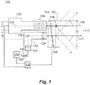
- Fig. 1 a partial view of an exemplary embodiment of a LIDAR system in accordance with the disclosure is shown in Fig. 1 and is designated generally by reference character 100.
- the systems and methods described herein can be used to simplify control and improve SWAP (size weight and power) characteristics in LIDAR systems.
- a LIDAR system 100 includes an imaging sensor 102 optically aligned with imaging optics 104, e.g., one or more lens elements, along a first optical path 106.
- a laser source 108 is optically aligned with laser optics 110 along a second optical path 112.
- a single scanning mechanism 114 is aligned with both the first optical path 106 and the second optical path 112 for directing outgoing laser illumination from the laser source 108 in a scanning direction D and for directing incoming laser return illumination to the imaging sensor 102 from the scanning direction D.
- the scanning direction D changes over time so the LIDAR system 100 can scan laser illumination pulses across a scene and detect the returns of the laser pulses reflected from the scene. Analysis of the time of flight for the laser pulses allows the LIDAR system 100 to construct a three-dimensional model of the scene.
- the first optical path 106 does not pass through the laser optics 110.
- the second optical path 112 does not pass through the imaging optics 104.
- the laser optics 110 and the imaging optics 104 are spaced apart from one another so the first optical path 106 bypasses the laser optics 110 and so the second optical path 112 bypasses the imaging optics 104.
- the first optical path 106 is free of fold mirrors.
- the second optical path 112 includes an optional fold mirror 116 diverting the second optical path 112, which allows the laser source 108 to be laterally offset from the second optical path 112.
- the single scanning mechanism 114 is a single Risley prism in which one or both of the prism elements 126 and 128 rotate relative to the housing 130. While shown and described as having two prims elements 126 and 128, those skilled in the art will readily appreciate that the Risley prism can have any suitable number of prism elements without departing from the scope of this disclosure.
- the Risley prism has diameter OD, e.g. a limiting aperture for the optical rays.
- the imaging optics 104 have a diameter d1, e.g. an outer diameter of an objective lens.
- the laser optics 110 have a diameter d2, e.g. an effective optical diameter.
- the diameter OD of the Risley prism is greater than the sum of the diameters d1 plus d2 of the laser optics 110 and imaging optics 104, sized to prevent optical vignetting on a mechanical surface of the scanning mechanism 114.
- the Risley prism has an effective optical diameter of two inches (5.08 cm)
- the imaging optics 104 can have an objective diameter of one inch (2.54 cm) or less
- the laser optics 110 can have an effective optical diameter of one inch (2.54 cm) or less.
- the laser source 108 includes a laser generator 118, which is incorporated as a LIDAR transmitter, with an optic fiber 120 optically coupling between the laser generator 118 and the laser optics 110, i.e. a portion of the second optical 112 path follows along the optic fiber 120.
- the laser optics 110 include a collimator 122, wherein the optic fiber 120 optically couples the laser generator 118 to the collimator 122.
- the laser optics 110 include a beam shaper 124 optically aligned between the scanning mechanism 114 and the collimator 122.
- the laser optics 110 include the fold mirror 116 that optically couples the collimator 122 and the beam shaper 124.
- the first and second optical paths 106 and 116 are parallel, i.e., co-aligned, to one another in at least a portion of the scanning mechanism 114, e.g., the first and second optical paths 106 and 116 are parallel to one another at least in the area between the inner prism element 126 of the Risley prism and the imaging and laser optics 104 and 110.
- the first and second optical paths 106 and 116 are parallel, i.e., co-aligned, throughout. They are mechanically set or boresighted to one another and they follow parallel paths through the LIDAR system 100 and can thus be parallel where they extend out of the LIDAR system 100 as well.
- the imaging sensor 102 is a focal plane array (FPA) configured to receive a two-dimensional image of the return illumination, which can be incorporated in a LIDAR transmitter 103.
- FPA focal plane array
- a controller 132 is operatively connected to the imaging sensor 102 for receiving image data characterizing the laser return illumination.
- the controller 132 is operatively connected to the laser source 108 for controlling and/or timing pulses of the outgoing laser illumination and for triggering/synchronizing the FPA with the laser pulse to capture imagery.
- the controller 132 is operatively connected to the scanning mechanism 114 for coordinating imaging from the imaging sensor 102 with scanning of the outgoing laser illumination and laser return illumination along the scanning direction D.
- LIDAR system 100 is shown with all the same components as described above with reference to Fig. 1 , however in Fig. 2 , a fold mirror 134 is included in the first optical path 106 diverting the first optical path 106 between the imaging optics 104 and the imaging sensor 102. This allows both the imaging sensor 102 and the laser generator 118 to be offset from the respective optical paths 106 and 112. As shown in Fig. 3 , another laser source configuration can be used wherein there is no fold mirror. In laser source 208, the collimator 222 and beam shaper 224 are optically coupled together along the second optical path 112 without an intervening fold mirror.
- the optic fiber 220 and laser generator 218 can also be positioned in line with the collimator 222 and beam shaper 224 as shown in Fig. 3 .
- the laser source 208 optionally can be used in lieu of the laser source 108 shown in either the configuration of Fig. 1 (in which case there are no fold mirrors in the optical paths 106 and 112) and/or Fig. 2 (in which case only the first optical path 106 includes a fold mirror 134).
- Systems and method as disclosed herein can eliminate the need for a multi-element scanning system (with multiple scanning mechanisms synchronized to one another). This can remove traditional limitations on scanning speed, whereas in traditional configurations highspeed scanning systems with small deviations in angular direction between two scanning mechanisms could result in significant mismatching at distance.
- Systems and methods as disclosed herein can also reduce SWAP (size weight and power) as the optics can be more closely packaged and space for additional scanning mechanisms is reduced relative to traditional systems. Parallax between LIDAR transmitter and receiver in systems and methods disclosed herein can be reduced and thus more easily corrected than in traditional systems.
Landscapes
- Physics & Mathematics (AREA)
- Engineering & Computer Science (AREA)
- General Physics & Mathematics (AREA)
- Radar, Positioning & Navigation (AREA)
- Remote Sensing (AREA)
- Computer Networks & Wireless Communication (AREA)
- Electromagnetism (AREA)
- Optics & Photonics (AREA)
- Optical Radar Systems And Details Thereof (AREA)
Abstract
Description
- The present disclosure relates to optical systems, and more particularly to LIDAR systems.
- LIDAR and rangefinder imaging systems require two primary components: a laser emitter, which includes a light source and optics, and an imaging receiver, which includes optics and a sensor, e.g. an imaging sensor in LIDAR cameras. Due to the size of each, these two primary components traditionally require separate scanning mechanisms to meet requirements for pointing accuracy and SWAP (size weight and power). The separate scanning mechanisms must be controlled to keep them synchronized which can be limiting in terms of high speeds.
- The conventional techniques have been considered satisfactory for their intended purpose. However, there is an ever present need for improved LIDAR systems. This disclosure provides a solution for this need.
- A LIDAR system includes an imaging sensor optically aligned with imaging optics along a first optical path. A laser source is optically aligned with laser optics along a second optical path. A single scanning mechanism is aligned with both the first optical path and the second optical path for directing outgoing laser illumination from the laser source in a scanning direction and for directing incoming laser return illumination from the scanning direction.
- In embodiments, the first optical path does not pass through the laser optics and the second optical path does not pass through the imaging optics. The laser optics and the imaging optics can be spaced apart from one another so the first optical path bypasses the laser optics and so the second optical path bypasses the imaging optics. At least one of the first and second optical paths can be free of fold mirrors. At least one of the first and second optical paths can include a fold mirror.
- The single scanning mechanism can be a single Risley prism having one or more prism elements. The Risley prism can have a diameter, wherein in the imaging optics have a diameter, and wherein the laser optics have a diameter, wherein the diameter of the Risley prism is greater than the diameters of the laser optics and imaging optics added together to prevent optical vignetting.
- The laser source can include a laser generator with an optic fiber optically coupling between the laser generator and the laser optics. The laser optics can include a collimator, wherein the optic fiber optically couples the laser generator to the collimator. The laser optics can include a beam shaper optically aligned between the scanning mechanism and the collimator. The laser optics can include a fold mirror that optically couples the collimator and the beam shaper. The laser optics can include a first fold mirror for diverting the first optical path wherein the imaging optics include a second fold mirror for diverting the second optical path. The first and second optical paths can be parallel to one another in at least a portion of the scanning mechanism.
- The imaging sensor can be a focal plane array (FPA) configured to receive a two-dimensional image of the return illumination. A controller can be operatively connected to the imaging sensor for receiving image data characterizing the laser return illumination, wherein the controller is operatively connected to the laser source for controlling and/or timing pulses of the outgoing laser illumination and for triggering/synchronizing the FPA with the laser pulse to capture an image, and is operatively connected to the scanning mechanism for coordinating imaging from the imaging sensor with scanning of the outgoing laser illumination and laser return illumination along the scanning direction.
- A method includes directing outgoing laser illumination from a laser with a scanning mechanism and directing incoming laser return illumination with the scanning mechanism to a sensor.
- These and other features of the systems and methods of the subject disclosure will become more readily apparent to those skilled in the art from the following detailed description of the preferred embodiments taken in conjunction with the drawings.
- So that those skilled in the art to which the subject disclosure appertains will readily understand how to make and use the devices and methods of the subject disclosure without undue experimentation, preferred embodiments thereof will be described in detail herein below with reference to certain figures, wherein:
-
Fig. 1 is a schematic view of an exemplary embodiment of a LIDAR system constructed in accordance with the present disclosure, showing the first and second optical paths passing through the scanning mechanism; -
Fig. 2 is a schematic view of another exemplary embodiment of a LIDAR system constructed in accordance with the present disclosure, showing both the first and second optical paths including a respective fold mirror; and -
Fig. 3 is a schematic view of an exemplary embodiment of a laser source and laser optics without a fold mirror for use in LIDAR systems such as inFigs. 1 and2 . - Reference will now be made to the drawings wherein like reference numerals identify similar structural features or aspects of the subject disclosure. For purposes of explanation and illustration, and not limitation, a partial view of an exemplary embodiment of a LIDAR system in accordance with the disclosure is shown in
Fig. 1 and is designated generally byreference character 100. Other embodiments of LIDAR systems in accordance with the disclosure, or aspects thereof, are provided inFigs. 2-3 , as will be described. The systems and methods described herein can be used to simplify control and improve SWAP (size weight and power) characteristics in LIDAR systems. - A LIDAR
system 100 includes animaging sensor 102 optically aligned withimaging optics 104, e.g., one or more lens elements, along a firstoptical path 106. Alaser source 108 is optically aligned withlaser optics 110 along a secondoptical path 112. Asingle scanning mechanism 114 is aligned with both the firstoptical path 106 and the secondoptical path 112 for directing outgoing laser illumination from thelaser source 108 in a scanning direction D and for directing incoming laser return illumination to theimaging sensor 102 from the scanning direction D. The scanning direction D changes over time so theLIDAR system 100 can scan laser illumination pulses across a scene and detect the returns of the laser pulses reflected from the scene. Analysis of the time of flight for the laser pulses allows the LIDARsystem 100 to construct a three-dimensional model of the scene. - The first
optical path 106 does not pass through thelaser optics 110. The secondoptical path 112 does not pass through theimaging optics 104. Thelaser optics 110 and theimaging optics 104 are spaced apart from one another so the firstoptical path 106 bypasses thelaser optics 110 and so the secondoptical path 112 bypasses theimaging optics 104. The firstoptical path 106 is free of fold mirrors. The secondoptical path 112 includes anoptional fold mirror 116 diverting the secondoptical path 112, which allows thelaser source 108 to be laterally offset from the secondoptical path 112. - The
single scanning mechanism 114 is a single Risley prism in which one or both of theprism elements prims elements imaging optics 104 have a diameter d1, e.g. an outer diameter of an objective lens. Thelaser optics 110 have a diameter d2, e.g. an effective optical diameter. The diameter OD of the Risley prism is greater than the sum of the diameters d1 plus d2 of thelaser optics 110 andimaging optics 104, sized to prevent optical vignetting on a mechanical surface of thescanning mechanism 114. For example, if the Risley prism has an effective optical diameter of two inches (5.08 cm), then theimaging optics 104 can have an objective diameter of one inch (2.54 cm) or less, and thelaser optics 110 can have an effective optical diameter of one inch (2.54 cm) or less. - The
laser source 108 includes alaser generator 118, which is incorporated as a LIDAR transmitter, with anoptic fiber 120 optically coupling between thelaser generator 118 and thelaser optics 110, i.e. a portion of the second optical 112 path follows along theoptic fiber 120. Those skilled in the art will readily appreciate that theoptic fiber 120 is optional, and that any other suitable arrangement, such as a direct coupled laser, can be used without departing from the scope of this disclosure. Thelaser optics 110 include acollimator 122, wherein theoptic fiber 120 optically couples thelaser generator 118 to thecollimator 122. Thelaser optics 110 include abeam shaper 124 optically aligned between thescanning mechanism 114 and thecollimator 122. Thelaser optics 110 include thefold mirror 116 that optically couples thecollimator 122 and thebeam shaper 124. The first and secondoptical paths scanning mechanism 114, e.g., the first and secondoptical paths inner prism element 126 of the Risley prism and the imaging andlaser optics optical paths LIDAR system 100 and can thus be parallel where they extend out of theLIDAR system 100 as well. - The
imaging sensor 102 is a focal plane array (FPA) configured to receive a two-dimensional image of the return illumination, which can be incorporated in aLIDAR transmitter 103. Those skilled in the art will readily appreciate that a single pixel sensor can also be used without departing from the scope of this disclosure. Acontroller 132 is operatively connected to theimaging sensor 102 for receiving image data characterizing the laser return illumination. Thecontroller 132 is operatively connected to thelaser source 108 for controlling and/or timing pulses of the outgoing laser illumination and for triggering/synchronizing the FPA with the laser pulse to capture imagery. Thecontroller 132 is operatively connected to thescanning mechanism 114 for coordinating imaging from theimaging sensor 102 with scanning of the outgoing laser illumination and laser return illumination along the scanning direction D. - With reference now to
Fig. 2 ,LIDAR system 100 is shown with all the same components as described above with reference toFig. 1 , however inFig. 2 , afold mirror 134 is included in the firstoptical path 106 diverting the firstoptical path 106 between theimaging optics 104 and theimaging sensor 102. This allows both theimaging sensor 102 and thelaser generator 118 to be offset from the respectiveoptical paths Fig. 3 , another laser source configuration can be used wherein there is no fold mirror. Inlaser source 208, thecollimator 222 andbeam shaper 224 are optically coupled together along the secondoptical path 112 without an intervening fold mirror. Optionally, the optic fiber 220 andlaser generator 218 can also be positioned in line with thecollimator 222 andbeam shaper 224 as shown inFig. 3 . Thelaser source 208 optionally can be used in lieu of thelaser source 108 shown in either the configuration ofFig. 1 (in which case there are no fold mirrors in theoptical paths 106 and 112) and/orFig. 2 (in which case only the firstoptical path 106 includes a fold mirror 134). - Systems and method as disclosed herein can eliminate the need for a multi-element scanning system (with multiple scanning mechanisms synchronized to one another). This can remove traditional limitations on scanning speed, whereas in traditional configurations highspeed scanning systems with small deviations in angular direction between two scanning mechanisms could result in significant mismatching at distance. Systems and methods as disclosed herein can also reduce SWAP (size weight and power) as the optics can be more closely packaged and space for additional scanning mechanisms is reduced relative to traditional systems. Parallax between LIDAR transmitter and receiver in systems and methods disclosed herein can be reduced and thus more easily corrected than in traditional systems.
- The methods and systems of the present disclosure, as described above and shown in the drawings, provide for LIDAR systems with superior properties relative to traditional systems including simplified control and improved SWAP (size weight and power) characteristics. While the apparatus and methods of the subject disclosure have been shown and described with reference to preferred embodiments, those skilled in the art will readily appreciate that changes and/or modifications may be made thereto without departing from the scope of the invention as defined by the claims.
Claims (15)
- A LIDAR system comprising:an imaging sensor (102) optically aligned with imaging optics (104) along a first optical path (106);a laser source (108) optically aligned with laser optics (110) along a second optical path (112); anda single scanning mechanism (114) aligned with both the first optical path and the second optical path for directing outgoing laser illumination from the laser source in a scanning direction and for directing incoming laser return illumination from the scanning direction.
- The system as recited in claim 1, wherein the first optical path does not pass through the laser optics, and/or
wherein the second optical path does not pass through the imaging optics. - The system as recited in claim 1, wherein the laser optics and the imaging optics are spaced apart from one another so the first optical path bypasses the laser optics and so the second optical path bypasses the imaging optics.
- The system as recited in any preceding claim, wherein at least one of the first and second optical paths is free of fold mirrors, or
wherein at least one of the first and second optical paths includes a fold mirror (134). - The system as recited in any preceding claim, wherein the single scanning mechanism is a single Risley prism having one or more prism elements (126, 128).
- The system as recited in claim 5, wherein the Risley prism has diameter, wherein in the imaging optics have a diameter, and wherein the laser optics have a diameter, wherein the diameter of the Risley prism is greater than the diameters of the laser optics and imaging optics added together to prevent optical vignetting.
- The system as recited in any preceding claim, wherein the laser source includes a laser generator (118) with an optic fiber (120)optically coupling between the laser generator and the laser optics.
- The system as recited in claim 7, wherein the laser optics include a collimator (122), wherein the optic fiber optically couples the laser generator to the collimator.
- The system as recited in claim 8, wherein the laser optics include a beam shaper (124) optically aligned between the scanning mechanism and the collimator.
- The system as recited in claim 9, wherein the laser optics include a fold mirror (134) that optically couples the collimator and the beam shaper.
- The system as recited in any preceding claim, wherein the laser optics include a first fold mirror for diverting the first optical path and wherein the imaging optics include a second fold mirror for diverting the second optical path.
- The system as recited in any preceding claim, further comprising a controller (132) operatively connected to the imaging sensor for receiving image data characterizing the laser return illumination, wherein the controller is operatively connected to the laser source for controlling and/or timing pulses of the outgoing laser illumination and for triggering/synchronizing the FPA with the laser pulse to capture an image, and is operatively connected to the scanning mechanism for coordinating imaging from the imaging sensor with scanning of the outgoing laser illumination and laser return illumination along the scanning direction.
- The system as recited in any preceding claim, wherein the imaging sensor is a focal plane array (FPA) configured to receive a two-dimensional image of the return illumination.
- The system as recited in any preceding claim, wherein the first and second optical paths are parallel to one another in at least a portion of the scanning mechanism.
- A method comprising:directing outgoing laser illumination from a laser with a scanning mechanism; anddirecting incoming laser return illumination with the scanning mechanism to a sensor.
Applications Claiming Priority (1)
| Application Number | Priority Date | Filing Date | Title |
|---|---|---|---|
| US16/131,747 US11408999B2 (en) | 2018-09-14 | 2018-09-14 | LIDAR camera systems |
Publications (2)
| Publication Number | Publication Date |
|---|---|
| EP3623839A1 true EP3623839A1 (en) | 2020-03-18 |
| EP3623839B1 EP3623839B1 (en) | 2025-07-16 |
Family
ID=67956628
Family Applications (1)
| Application Number | Title | Priority Date | Filing Date |
|---|---|---|---|
| EP19197398.1A Active EP3623839B1 (en) | 2018-09-14 | 2019-09-13 | Lidar camera systems |
Country Status (2)
| Country | Link |
|---|---|
| US (1) | US11408999B2 (en) |
| EP (1) | EP3623839B1 (en) |
Families Citing this family (1)
| Publication number | Priority date | Publication date | Assignee | Title |
|---|---|---|---|---|
| CN117890885B (en) * | 2024-03-15 | 2024-06-04 | 之江实验室 | Laser radar scanning mechanism and scanning method thereof |
Citations (3)
| Publication number | Priority date | Publication date | Assignee | Title |
|---|---|---|---|---|
| US20130293681A1 (en) * | 2010-12-23 | 2013-11-07 | Fastree3D S.A. | 2d/3d real-time imager and corresponding imaging methods |
| US20170350983A1 (en) * | 2016-06-01 | 2017-12-07 | Velodyne Lidar, Inc. | Multiple Pixel Scanning LIDAR |
| US20180081094A1 (en) * | 2016-09-20 | 2018-03-22 | Apple Inc. | Retroreflectors |
Family Cites Families (15)
| Publication number | Priority date | Publication date | Assignee | Title |
|---|---|---|---|---|
| JPH11109285A (en) * | 1997-09-30 | 1999-04-23 | Sony Corp | Projection type liquid crystal display |
| JP2000101515A (en) | 1998-07-21 | 2000-04-07 | Asahi Precision Co Ltd | Transmission/reception integrated optical communication equipment |
| EP1259841A4 (en) * | 2000-02-01 | 2005-09-07 | Soquel Technology Inc | SINGLE CHANNEL M x N OPTICAL FIBER SWITCH |
| US6836364B2 (en) * | 2002-03-18 | 2004-12-28 | Metastable Instruments, Inc. | Beam steering and scanning device |
| GB2414294B (en) * | 2004-05-20 | 2006-08-02 | Teraview Ltd | Apparatus and method for investigating a sample |
| US8421003B2 (en) | 2010-04-30 | 2013-04-16 | Raytheon Company | Optical transceiver built-in test (BIT) |
| US9456746B2 (en) * | 2013-03-15 | 2016-10-04 | Carl Zeiss Meditec, Inc. | Systems and methods for broad line fundus imaging |
| US8836922B1 (en) | 2013-08-20 | 2014-09-16 | Google Inc. | Devices and methods for a rotating LIDAR platform with a shared transmit/receive path |
| US10215846B2 (en) * | 2015-11-20 | 2019-02-26 | Texas Instruments Incorporated | Compact chip scale LIDAR solution |
| US10408940B2 (en) * | 2016-09-25 | 2019-09-10 | James Thomas O'Keeffe | Remote lidar with coherent fiber optic image bundle |
| CN108072877A (en) * | 2016-11-10 | 2018-05-25 | 光宝电子(广州)有限公司 | Optical devices |
| TW201823674A (en) * | 2016-12-29 | 2018-07-01 | 鴻海精密工業股份有限公司 | Laser distance measuring device |
| CN110199204A (en) * | 2017-03-29 | 2019-09-03 | 深圳市大疆创新科技有限公司 | LiDAR sensor system with small form factor |
| US10401481B2 (en) * | 2017-03-30 | 2019-09-03 | Luminar Technologies, Inc. | Non-uniform beam power distribution for a laser operating in a vehicle |
| US10884108B2 (en) * | 2017-11-28 | 2021-01-05 | National Chung Shan Institute Of Science And Technology | Light detection and ranging system |
-
2018
- 2018-09-14 US US16/131,747 patent/US11408999B2/en active Active
-
2019
- 2019-09-13 EP EP19197398.1A patent/EP3623839B1/en active Active
Patent Citations (3)
| Publication number | Priority date | Publication date | Assignee | Title |
|---|---|---|---|---|
| US20130293681A1 (en) * | 2010-12-23 | 2013-11-07 | Fastree3D S.A. | 2d/3d real-time imager and corresponding imaging methods |
| US20170350983A1 (en) * | 2016-06-01 | 2017-12-07 | Velodyne Lidar, Inc. | Multiple Pixel Scanning LIDAR |
| US20180081094A1 (en) * | 2016-09-20 | 2018-03-22 | Apple Inc. | Retroreflectors |
Also Published As
| Publication number | Publication date |
|---|---|
| US20200088880A1 (en) | 2020-03-19 |
| EP3623839B1 (en) | 2025-07-16 |
| US11408999B2 (en) | 2022-08-09 |
Similar Documents
| Publication | Publication Date | Title |
|---|---|---|
| EP2115515B1 (en) | Common-aperture optical system incorporating a light sensor and a light source | |
| EP3037864B1 (en) | Rotatable oblique-viewing stereoendoscope | |
| US11525677B2 (en) | Surveying apparatus for surveying an object | |
| US20140009611A1 (en) | Camera System and Method for Observing Objects at Great Distances, in Particular for Monitoring Target Objects at Night, in Mist, Dust or Rain | |
| US10119815B2 (en) | Binocular with integrated laser rangefinder | |
| US11493632B2 (en) | Tracker of a surveying apparatus for tracking a target | |
| US7405877B1 (en) | Stereoscopic endoscope | |
| US8773646B2 (en) | Fiber optic scanner | |
| US5530246A (en) | Viewing system | |
| KR20200038678A (en) | Complex optical sighting device | |
| WO2014038397A1 (en) | Stereoscopic optical system | |
| EP3623839B1 (en) | Lidar camera systems | |
| RU2593524C1 (en) | Scanning multi-wave lidar for atmospheric objects probing | |
| US7327513B2 (en) | Method and apparatus for viewing target | |
| US5764417A (en) | Compact optical device for night vision and its application to goggles | |
| GB2101352A (en) | Optical-mechanical scanner | |
| CN106597422B (en) | Miniaturization photo-electricity passive ranging device | |
| US5200622A (en) | Self-checked optronic system of infra-red observation and laser designation pod including such a system | |
| US11619711B2 (en) | Scanning system and transmitting and receiving device for a scanning system | |
| JP5278890B2 (en) | Light capture and tracking device | |
| KR101082382B1 (en) | Three dimensional photographing lens system | |
| EP4388345A1 (en) | Adaptive area flash lidar sensor | |
| CN208805582U (en) | A kind of big visual field sniper laser scanning, detecting device | |
| US12613078B2 (en) | Imaging apparatus with thermal augmentation | |
| US12596005B2 (en) | Method for operating a geodetic instrument, and related geodetic instrument |
Legal Events
| Date | Code | Title | Description |
|---|---|---|---|
| PUAI | Public reference made under article 153(3) epc to a published international application that has entered the european phase |
Free format text: ORIGINAL CODE: 0009012 |
|
| STAA | Information on the status of an ep patent application or granted ep patent |
Free format text: STATUS: THE APPLICATION HAS BEEN PUBLISHED |
|
| AK | Designated contracting states |
Kind code of ref document: A1 Designated state(s): AL AT BE BG CH CY CZ DE DK EE ES FI FR GB GR HR HU IE IS IT LI LT LU LV MC MK MT NL NO PL PT RO RS SE SI SK SM TR |
|
| AX | Request for extension of the european patent |
Extension state: BA ME |
|
| STAA | Information on the status of an ep patent application or granted ep patent |
Free format text: STATUS: REQUEST FOR EXAMINATION WAS MADE |
|
| 17P | Request for examination filed |
Effective date: 20200918 |
|
| RBV | Designated contracting states (corrected) |
Designated state(s): AL AT BE BG CH CY CZ DE DK EE ES FI FR GB GR HR HU IE IS IT LI LT LU LV MC MK MT NL NO PL PT RO RS SE SI SK SM TR |
|
| STAA | Information on the status of an ep patent application or granted ep patent |
Free format text: STATUS: EXAMINATION IS IN PROGRESS |
|
| 17Q | First examination report despatched |
Effective date: 20220110 |
|
| P01 | Opt-out of the competence of the unified patent court (upc) registered |
Effective date: 20230922 |
|
| GRAP | Despatch of communication of intention to grant a patent |
Free format text: ORIGINAL CODE: EPIDOSNIGR1 |
|
| STAA | Information on the status of an ep patent application or granted ep patent |
Free format text: STATUS: GRANT OF PATENT IS INTENDED |
|
| INTG | Intention to grant announced |
Effective date: 20241111 |
|
| GRAJ | Information related to disapproval of communication of intention to grant by the applicant or resumption of examination proceedings by the epo deleted |
Free format text: ORIGINAL CODE: EPIDOSDIGR1 |
|
| STAA | Information on the status of an ep patent application or granted ep patent |
Free format text: STATUS: EXAMINATION IS IN PROGRESS |
|
| GRAP | Despatch of communication of intention to grant a patent |
Free format text: ORIGINAL CODE: EPIDOSNIGR1 |
|
| STAA | Information on the status of an ep patent application or granted ep patent |
Free format text: STATUS: GRANT OF PATENT IS INTENDED |
|
| INTC | Intention to grant announced (deleted) | ||
| INTG | Intention to grant announced |
Effective date: 20250306 |
|
| GRAS | Grant fee paid |
Free format text: ORIGINAL CODE: EPIDOSNIGR3 |
|
| GRAA | (expected) grant |
Free format text: ORIGINAL CODE: 0009210 |
|
| STAA | Information on the status of an ep patent application or granted ep patent |
Free format text: STATUS: THE PATENT HAS BEEN GRANTED |
|
| AK | Designated contracting states |
Kind code of ref document: B1 Designated state(s): AL AT BE BG CH CY CZ DE DK EE ES FI FR GB GR HR HU IE IS IT LI LT LU LV MC MK MT NL NO PL PT RO RS SE SI SK SM TR |
|
| REG | Reference to a national code |
Ref country code: GB Ref legal event code: FG4D |
|
| REG | Reference to a national code |
Ref country code: CH Ref legal event code: EP Ref country code: DE Ref legal event code: R096 Ref document number: 602019072552 Country of ref document: DE |
|
| REG | Reference to a national code |
Ref country code: IE Ref legal event code: FG4D |
|
| PGFP | Annual fee paid to national office [announced via postgrant information from national office to epo] |
Ref country code: DE Payment date: 20250820 Year of fee payment: 7 |
|
| PGFP | Annual fee paid to national office [announced via postgrant information from national office to epo] |
Ref country code: GB Payment date: 20250822 Year of fee payment: 7 |
|
| PGFP | Annual fee paid to national office [announced via postgrant information from national office to epo] |
Ref country code: FR Payment date: 20250821 Year of fee payment: 7 |
|
| REG | Reference to a national code |
Ref country code: NL Ref legal event code: MP Effective date: 20250716 |
|
| PG25 | Lapsed in a contracting state [announced via postgrant information from national office to epo] |
Ref country code: PT Free format text: LAPSE BECAUSE OF FAILURE TO SUBMIT A TRANSLATION OF THE DESCRIPTION OR TO PAY THE FEE WITHIN THE PRESCRIBED TIME-LIMIT Effective date: 20251117 |
|
| PG25 | Lapsed in a contracting state [announced via postgrant information from national office to epo] |
Ref country code: NL Free format text: LAPSE BECAUSE OF FAILURE TO SUBMIT A TRANSLATION OF THE DESCRIPTION OR TO PAY THE FEE WITHIN THE PRESCRIBED TIME-LIMIT Effective date: 20250716 |
|
| REG | Reference to a national code |
Ref country code: AT Ref legal event code: MK05 Ref document number: 1814495 Country of ref document: AT Kind code of ref document: T Effective date: 20250716 |
|
| PG25 | Lapsed in a contracting state [announced via postgrant information from national office to epo] |
Ref country code: IS Free format text: LAPSE BECAUSE OF FAILURE TO SUBMIT A TRANSLATION OF THE DESCRIPTION OR TO PAY THE FEE WITHIN THE PRESCRIBED TIME-LIMIT Effective date: 20251116 |
|
| PG25 | Lapsed in a contracting state [announced via postgrant information from national office to epo] |
Ref country code: NO Free format text: LAPSE BECAUSE OF FAILURE TO SUBMIT A TRANSLATION OF THE DESCRIPTION OR TO PAY THE FEE WITHIN THE PRESCRIBED TIME-LIMIT Effective date: 20251016 |
|
| REG | Reference to a national code |
Ref country code: LT Ref legal event code: MG9D |
|
| PG25 | Lapsed in a contracting state [announced via postgrant information from national office to epo] |
Ref country code: AT Free format text: LAPSE BECAUSE OF FAILURE TO SUBMIT A TRANSLATION OF THE DESCRIPTION OR TO PAY THE FEE WITHIN THE PRESCRIBED TIME-LIMIT Effective date: 20250716 |
|
| PG25 | Lapsed in a contracting state [announced via postgrant information from national office to epo] |
Ref country code: FI Free format text: LAPSE BECAUSE OF FAILURE TO SUBMIT A TRANSLATION OF THE DESCRIPTION OR TO PAY THE FEE WITHIN THE PRESCRIBED TIME-LIMIT Effective date: 20250716 |
|
| PG25 | Lapsed in a contracting state [announced via postgrant information from national office to epo] |
Ref country code: HR Free format text: LAPSE BECAUSE OF FAILURE TO SUBMIT A TRANSLATION OF THE DESCRIPTION OR TO PAY THE FEE WITHIN THE PRESCRIBED TIME-LIMIT Effective date: 20250716 |
|
| PG25 | Lapsed in a contracting state [announced via postgrant information from national office to epo] |
Ref country code: GR Free format text: LAPSE BECAUSE OF FAILURE TO SUBMIT A TRANSLATION OF THE DESCRIPTION OR TO PAY THE FEE WITHIN THE PRESCRIBED TIME-LIMIT Effective date: 20251017 |
|
| PG25 | Lapsed in a contracting state [announced via postgrant information from national office to epo] |
Ref country code: SE Free format text: LAPSE BECAUSE OF FAILURE TO SUBMIT A TRANSLATION OF THE DESCRIPTION OR TO PAY THE FEE WITHIN THE PRESCRIBED TIME-LIMIT Effective date: 20250716 |
|
| PG25 | Lapsed in a contracting state [announced via postgrant information from national office to epo] |
Ref country code: LV Free format text: LAPSE BECAUSE OF FAILURE TO SUBMIT A TRANSLATION OF THE DESCRIPTION OR TO PAY THE FEE WITHIN THE PRESCRIBED TIME-LIMIT Effective date: 20250716 |
|
| PG25 | Lapsed in a contracting state [announced via postgrant information from national office to epo] |
Ref country code: BG Free format text: LAPSE BECAUSE OF FAILURE TO SUBMIT A TRANSLATION OF THE DESCRIPTION OR TO PAY THE FEE WITHIN THE PRESCRIBED TIME-LIMIT Effective date: 20250716 Ref country code: PL Free format text: LAPSE BECAUSE OF FAILURE TO SUBMIT A TRANSLATION OF THE DESCRIPTION OR TO PAY THE FEE WITHIN THE PRESCRIBED TIME-LIMIT Effective date: 20250716 |
|
| PG25 | Lapsed in a contracting state [announced via postgrant information from national office to epo] |
Ref country code: RS Free format text: LAPSE BECAUSE OF FAILURE TO SUBMIT A TRANSLATION OF THE DESCRIPTION OR TO PAY THE FEE WITHIN THE PRESCRIBED TIME-LIMIT Effective date: 20251016 |
|
| PG25 | Lapsed in a contracting state [announced via postgrant information from national office to epo] |
Ref country code: ES Free format text: LAPSE BECAUSE OF FAILURE TO SUBMIT A TRANSLATION OF THE DESCRIPTION OR TO PAY THE FEE WITHIN THE PRESCRIBED TIME-LIMIT Effective date: 20250716 |
|
| PG25 | Lapsed in a contracting state [announced via postgrant information from national office to epo] |
Ref country code: RO Free format text: LAPSE BECAUSE OF FAILURE TO SUBMIT A TRANSLATION OF THE DESCRIPTION OR TO PAY THE FEE WITHIN THE PRESCRIBED TIME-LIMIT Effective date: 20250716 |
|
| PG25 | Lapsed in a contracting state [announced via postgrant information from national office to epo] |
Ref country code: SM Free format text: LAPSE BECAUSE OF FAILURE TO SUBMIT A TRANSLATION OF THE DESCRIPTION OR TO PAY THE FEE WITHIN THE PRESCRIBED TIME-LIMIT Effective date: 20250716 |
|
| PG25 | Lapsed in a contracting state [announced via postgrant information from national office to epo] |
Ref country code: DK Free format text: LAPSE BECAUSE OF FAILURE TO SUBMIT A TRANSLATION OF THE DESCRIPTION OR TO PAY THE FEE WITHIN THE PRESCRIBED TIME-LIMIT Effective date: 20250716 |
|
| PG25 | Lapsed in a contracting state [announced via postgrant information from national office to epo] |
Ref country code: IT Free format text: LAPSE BECAUSE OF FAILURE TO SUBMIT A TRANSLATION OF THE DESCRIPTION OR TO PAY THE FEE WITHIN THE PRESCRIBED TIME-LIMIT Effective date: 20250716 |
|
| PG25 | Lapsed in a contracting state [announced via postgrant information from national office to epo] |
Ref country code: CZ Free format text: LAPSE BECAUSE OF FAILURE TO SUBMIT A TRANSLATION OF THE DESCRIPTION OR TO PAY THE FEE WITHIN THE PRESCRIBED TIME-LIMIT Effective date: 20250716 |
|
| REG | Reference to a national code |
Ref country code: CH Ref legal event code: H13 Free format text: ST27 STATUS EVENT CODE: U-0-0-H10-H13 (AS PROVIDED BY THE NATIONAL OFFICE) Effective date: 20260425 |
|
| PG25 | Lapsed in a contracting state [announced via postgrant information from national office to epo] |
Ref country code: EE Free format text: LAPSE BECAUSE OF FAILURE TO SUBMIT A TRANSLATION OF THE DESCRIPTION OR TO PAY THE FEE WITHIN THE PRESCRIBED TIME-LIMIT Effective date: 20250716 Ref country code: SK Free format text: LAPSE BECAUSE OF FAILURE TO SUBMIT A TRANSLATION OF THE DESCRIPTION OR TO PAY THE FEE WITHIN THE PRESCRIBED TIME-LIMIT Effective date: 20250716 |