EP3623790B1 - Embedded non-intrusive stress measurement system probe - Google Patents
Embedded non-intrusive stress measurement system probe Download PDFInfo
- Publication number
- EP3623790B1 EP3623790B1 EP19186112.9A EP19186112A EP3623790B1 EP 3623790 B1 EP3623790 B1 EP 3623790B1 EP 19186112 A EP19186112 A EP 19186112A EP 3623790 B1 EP3623790 B1 EP 3623790B1
- Authority
- EP
- European Patent Office
- Prior art keywords
- housing
- tube
- probe
- coupled
- channel
- Prior art date
- Legal status (The legal status is an assumption and is not a legal conclusion. Google has not performed a legal analysis and makes no representation as to the accuracy of the status listed.)
- Active
Links
Images



Classifications
-
- G—PHYSICS
- G01—MEASURING; TESTING
- G01M—TESTING STATIC OR DYNAMIC BALANCE OF MACHINES OR STRUCTURES; TESTING OF STRUCTURES OR APPARATUS, NOT OTHERWISE PROVIDED FOR
- G01M15/00—Testing of engines
- G01M15/14—Testing gas-turbine engines or jet-propulsion engines
-
- F—MECHANICAL ENGINEERING; LIGHTING; HEATING; WEAPONS; BLASTING
- F01—MACHINES OR ENGINES IN GENERAL; ENGINE PLANTS IN GENERAL; STEAM ENGINES
- F01D—NON-POSITIVE DISPLACEMENT MACHINES OR ENGINES, e.g. STEAM TURBINES
- F01D21/00—Shutting-down of machines or engines, e.g. in emergency; Regulating, controlling, or safety means not otherwise provided for
- F01D21/003—Arrangements for testing or measuring
-
- F—MECHANICAL ENGINEERING; LIGHTING; HEATING; WEAPONS; BLASTING
- F01—MACHINES OR ENGINES IN GENERAL; ENGINE PLANTS IN GENERAL; STEAM ENGINES
- F01D—NON-POSITIVE DISPLACEMENT MACHINES OR ENGINES, e.g. STEAM TURBINES
- F01D25/00—Component parts, details, or accessories, not provided for in, or of interest apart from, other groups
- F01D25/24—Casings; Casing parts, e.g. diaphragms, casing fastenings
-
- F—MECHANICAL ENGINEERING; LIGHTING; HEATING; WEAPONS; BLASTING
- F02—COMBUSTION ENGINES; HOT-GAS OR COMBUSTION-PRODUCT ENGINE PLANTS
- F02C—GAS-TURBINE PLANTS; AIR INTAKES FOR JET-PROPULSION PLANTS; CONTROLLING FUEL SUPPLY IN AIR-BREATHING JET-PROPULSION PLANTS
- F02C3/00—Gas-turbine plants characterised by the use of combustion products as the working fluid
- F02C3/04—Gas-turbine plants characterised by the use of combustion products as the working fluid having a turbine driving a compressor
-
- F—MECHANICAL ENGINEERING; LIGHTING; HEATING; WEAPONS; BLASTING
- F02—COMBUSTION ENGINES; HOT-GAS OR COMBUSTION-PRODUCT ENGINE PLANTS
- F02C—GAS-TURBINE PLANTS; AIR INTAKES FOR JET-PROPULSION PLANTS; CONTROLLING FUEL SUPPLY IN AIR-BREATHING JET-PROPULSION PLANTS
- F02C7/00—Features, components parts, details or accessories, not provided for in, or of interest apart form groups F02C1/00 - F02C6/00; Air intakes for jet-propulsion plants
-
- F—MECHANICAL ENGINEERING; LIGHTING; HEATING; WEAPONS; BLASTING
- F02—COMBUSTION ENGINES; HOT-GAS OR COMBUSTION-PRODUCT ENGINE PLANTS
- F02K—JET-PROPULSION PLANTS
- F02K3/00—Plants including a gas turbine driving a compressor or a ducted fan
- F02K3/02—Plants including a gas turbine driving a compressor or a ducted fan in which part of the working fluid by-passes the turbine and combustion chamber
- F02K3/04—Plants including a gas turbine driving a compressor or a ducted fan in which part of the working fluid by-passes the turbine and combustion chamber the plant including ducted fans, i.e. fans with high volume, low pressure outputs, for augmenting the jet thrust, e.g. of double-flow type
- F02K3/06—Plants including a gas turbine driving a compressor or a ducted fan in which part of the working fluid by-passes the turbine and combustion chamber the plant including ducted fans, i.e. fans with high volume, low pressure outputs, for augmenting the jet thrust, e.g. of double-flow type with front fan
-
- G—PHYSICS
- G01—MEASURING; TESTING
- G01H—MEASUREMENT OF MECHANICAL VIBRATIONS OR ULTRASONIC, SONIC OR INFRASONIC WAVES
- G01H9/00—Measuring mechanical vibrations or ultrasonic, sonic or infrasonic waves by using radiation-sensitive means, e.g. optical means
- G01H9/004—Measuring mechanical vibrations or ultrasonic, sonic or infrasonic waves by using radiation-sensitive means, e.g. optical means using fibre optic sensors
-
- G—PHYSICS
- G01—MEASURING; TESTING
- G01M—TESTING STATIC OR DYNAMIC BALANCE OF MACHINES OR STRUCTURES; TESTING OF STRUCTURES OR APPARATUS, NOT OTHERWISE PROVIDED FOR
- G01M5/00—Investigating the elasticity of structures, e.g. deflection of bridges or air-craft wings
- G01M5/0041—Investigating the elasticity of structures, e.g. deflection of bridges or air-craft wings by determining deflection or stress
-
- G—PHYSICS
- G01—MEASURING; TESTING
- G01M—TESTING STATIC OR DYNAMIC BALANCE OF MACHINES OR STRUCTURES; TESTING OF STRUCTURES OR APPARATUS, NOT OTHERWISE PROVIDED FOR
- G01M5/00—Investigating the elasticity of structures, e.g. deflection of bridges or air-craft wings
- G01M5/0066—Investigating the elasticity of structures, e.g. deflection of bridges or air-craft wings by exciting or detecting vibration or acceleration
-
- G—PHYSICS
- G01—MEASURING; TESTING
- G01M—TESTING STATIC OR DYNAMIC BALANCE OF MACHINES OR STRUCTURES; TESTING OF STRUCTURES OR APPARATUS, NOT OTHERWISE PROVIDED FOR
- G01M5/00—Investigating the elasticity of structures, e.g. deflection of bridges or air-craft wings
- G01M5/0091—Investigating the elasticity of structures, e.g. deflection of bridges or air-craft wings by using electromagnetic excitation or detection
-
- F—MECHANICAL ENGINEERING; LIGHTING; HEATING; WEAPONS; BLASTING
- F05—INDEXING SCHEMES RELATING TO ENGINES OR PUMPS IN VARIOUS SUBCLASSES OF CLASSES F01-F04
- F05D—INDEXING SCHEME FOR ASPECTS RELATING TO NON-POSITIVE-DISPLACEMENT MACHINES OR ENGINES, GAS-TURBINES OR JET-PROPULSION PLANTS
- F05D2260/00—Function
- F05D2260/80—Diagnostics
-
- F—MECHANICAL ENGINEERING; LIGHTING; HEATING; WEAPONS; BLASTING
- F05—INDEXING SCHEMES RELATING TO ENGINES OR PUMPS IN VARIOUS SUBCLASSES OF CLASSES F01-F04
- F05D—INDEXING SCHEME FOR ASPECTS RELATING TO NON-POSITIVE-DISPLACEMENT MACHINES OR ENGINES, GAS-TURBINES OR JET-PROPULSION PLANTS
- F05D2270/00—Control
- F05D2270/80—Devices generating input signals, e.g. transducers, sensors, cameras or strain gauges
-
- G—PHYSICS
- G01—MEASURING; TESTING
- G01H—MEASUREMENT OF MECHANICAL VIBRATIONS OR ULTRASONIC, SONIC OR INFRASONIC WAVES
- G01H1/00—Measuring characteristics of vibrations in solids by using direct conduction to the detector
- G01H1/003—Measuring characteristics of vibrations in solids by using direct conduction to the detector of rotating machines
- G01H1/006—Measuring characteristics of vibrations in solids by using direct conduction to the detector of rotating machines of the rotor of turbo machines
Definitions
- the present disclosure relates to Non-intrusive Stress Measurement System (NSMS) probes, and more particularly, to low profile multi-fiber NSMS probes for turbomachinery and gas turbine engines.
- NSMS Non-intrusive Stress Measurement System
- a gas turbine engine typically includes a fan section, a compressor section, a combustor section and a turbine section.
- the fan section and compressor section together are typically referred to as the cold section.
- the combustor section and turbine section together are typically referred to as the hot section.
- Bladed disk turbomachinery of the cold section and the turbine section rotate at great speed which places the blades under severe stress. For operational analysis and safety it is desirable to monitor these stresses.
- Non-intrusive Stress Measurement System are systems which monitor these stresses without relying on sensors integral to or intruding on the rotating turbomachinery.
- NSMS sensors i.e. probes mounted within the geometry of structures (such as, for example, a case) external to the blade disk are used to measure each blade's behavior including vibratory response characteristics such as stress, phase, frequency, resonance, and damping.
- a prior art un-lensed non-intrusive stress measurement system probe having the features of the preamble of claim 1 is disclosed in EP 2 341 324 A2 . Further prior art apparatuses are disclosed in US 2016/194976 A1 and WO 2007/115314 A2 .
- the present invention provides an un-lensed non-intrusive stress measurement system probe as set forth in claim 1.
- the plurality of optical fibers comprises at least one of a transmit fiber and a receive fiber.
- the plurality of optical fibers are arranged in an expendable fiber arrangement holder, wherein the expendable fiber arrangement holder is coupled at the sensing aperture.
- the first hypotube is filled with an epoxy.
- the epoxy is cured and the expendable fiber arrangement holder is polished flush with the optical face in response to bending the first hypotube along the radiused portion.
- the housing is disposed within a cavity defined by an annular wall about a first annulus of a first annular disk, wherein the housing comprises barrel inserted into the first annulus of the first annular disk, wherein a second annular disk comprising a second annulus defined by the outer diameter of the annular wall is coupled at the second annulus to the annular wall.
- the present invention provides a gas turbine engine as set forth in claim 7.
- the present invention provides a method of manufacturing an un-lensed non-intrusive stress measurement system probe as set forth in claim 10.
- Gas turbine engine 20 may be a two-spool turbofan that generally incorporates a fan section 22, a compressor section 24, a combustor section 26 and a turbine section 28.
- fan section 22 can drive air along a bypass flow-path B while compressor section 24 can drive air for compression and communication into combustor section 26 then expansion through turbine section 28.
- turbofan gas turbine engine 20 depicted as a turbofan gas turbine engine 20 herein, it should be understood that the concepts described herein are not limited to use with turbofans as the teachings may be applied to other types of turbine engines including turbojet engines, a lowbypass turbofans, a high bypass turbofans, or any other gas turbine known to those skilled in the art.
- Gas turbine engine 20 may generally comprise a low speed spool 30 and a high speed spool 32 mounted for rotation about an engine central longitudinal axis A-A' relative to an engine static structure 36 via one or more bearing systems 38 (shown as bearing system 38-1 and bearing system 38-2). It should be understood that various bearing systems 38 at various locations may alternatively or additionally be provided, including for example, bearing system 38, bearing system 38-1, and bearing system 38-2.
- Low speed spool 30 may generally comprise an inner shaft 40 that interconnects a fan 42, a low pressure (or first) compressor section 44 (also referred to a low pressure compressor) and a low pressure (or first) turbine section 46.
- Inner shaft 40 may be connected to fan 42 through a geared architecture 48 that can drive fan 42 at a lower speed than low speed spool 30.
- Geared architecture 48 may comprise a gear assembly 60 enclosed within a gear housing 62.
- Gear assembly 60 couples inner shaft 40 to a rotating fan structure.
- High speed spool 32 may comprise an outer shaft 50 that interconnects a high pressure compressor (“HPC") 52 (e.g., a second compressor section) and high pressure (or second) turbine section 54.
- HPC high pressure compressor
- a combustor 56 may be located between HPC 52 and high pressure turbine 54.
- a mid-turbine frame 57 of engine static structure 36 may be located generally between high pressure turbine 54 and low pressure turbine 46.
- Mid-turbine frame 57 may support one or more bearing systems 38 in turbine section 28.
- Inner shaft 40 and outer shaft 50 may be concentric and rotate via bearing systems 38 about the engine central longitudinal axis A-A', which is collinear with their longitudinal axes.
- a "high pressure" compressor or turbine experiences a higher pressure than a corresponding "low pressure” compressor or turbine.
- the core airflow C may be compressed by low pressure compressor 44 then HPC 52, mixed and burned with fuel in combustor 56, then expanded over high pressure turbine 54 and low pressure turbine 46.
- Mid-turbine frame 57 includes airfoils 59 which are in the core airflow path.
- Low pressure turbine 46, and high pressure turbine 54 rotationally drive the respective low speed spool 30 and high speed spool 32 in response to the expansion.
- Gas turbine engine 20 may be, for example, a high-bypass geared aircraft engine. In various embodiments, the bypass ratio of gas turbine engine 20 may be greater than about six. In various embodiments, the bypass ratio of gas turbine engine 20 may be greater than ten.
- geared architecture 48 may be an epicyclic gear train, such as a star gear system (sun gear in meshing engagement with a plurality of star gears supported by a carrier and in meshing engagement with a ring gear) or other gear system. Geared architecture 48 may have a gear reduction ratio of greater than about 2.3 and low pressure turbine 46 may have a pressure ratio that is greater than about 5. In various embodiments, the bypass ratio of gas turbine engine 20 is greater than about ten.
- the diameter of fan 42 may be significantly larger than that of the low pressure compressor 44, and the low pressure turbine 46 may have a pressure ratio that is greater than about.
- Low pressure turbine 46 pressure ratio may be measured prior to inlet of low pressure turbine 46 as related to the pressure at the outlet of low pressure turbine 46 prior to an exhaust nozzle. It should be understood, however, that the above parameters are exemplary of various embodiments of a suitable geared architecture engine and that the present disclosure contemplates other gas turbine engines including direct drive turbofans.
- the next generation of turbofan engines may be designed for higher efficiency which is associated with higher pressure ratios and higher temperatures in the HPC 52. These higher operating temperatures and pressure ratios may create operating environments that may cause thermal loads that are higher than the thermal loads encountered in conventional turbofan engines, which may shorten the operational life of current components.
- HPC 52 may comprise alternating rows of rotating rotors and stationary stators.
- Stators may have a cantilevered configuration or a shrouded configuration.
- a stator may comprise a stator vane, a casing support and a hub support.
- a stator vane may be supported along an outer diameter by a casing support and along an inner diameter by a hub support.
- a cantilevered stator may comprise a stator vane that is only retained and/or supported at the casing (e.g., along an outer diameter).
- rotors may be configured to compress and spin a fluid flow.
- Stators may be configured to receive and straighten the fluid flow.
- the fluid flow discharged from the trailing edge of stators may be straightened (e.g., the flow may be directed in a substantially parallel path to the centerline of the engine and/or HPC) to increase and/or improve the efficiency of the engine and, more specifically, to achieve maximum and/or near maximum compression and efficiency when the straightened air is compressed and spun by rotor 64.
- one or more low profile un-lensed NSMS probes 200 may be located within the geometries of gas turbine engine 20 structures such as, for example, a fan case of fan section 22, a compressor case of compressor section 24, a combustor case of combustor section 26 and or the like.
- a plurality of low profile un-lensed NSMS probes 200 may be located axially or circumferentially about a case.
- a low profile un-lensed NSMS probe 200 (hereinafter probe 200) is shown mounted to a case 202.
- Case 202 may comprise an outer gas path surface 206 and surround a rotating component of turbomachinery such as blade 216.
- a rub strip 204 comprising an inner gas path surface 214 may be coupled radially inward (relative to the axis of rotation of blade 216) of case 202 between the case 202 and the blade 216.
- Probe 200 is coupled at lip 210 of case 202 which extends inward (along the X-axis) within a first bore 208 through outer gas path surface 206 of case 202 thereby forming an annular structure within the first bore 208.
- a corresponding second bore 212 through inner gas path surface 214 of rub strip 204 may tend to facilitate coupling of probe 200 to case 202.
- probe 200 is shown in cross section through the X-Y plane.
- Probe 200 comprises housing 300 which retains an inner hypotube configured to contain a plurality of optical fibers.
- Housing 300 is disposed within a cavity formed by an annular wall of inner collar 302.
- Housing 300 is sealed by a cap 306 coupled to an outer hypotube 308 which shields the inner hypotube 310.
- An outer collar 304 is coupled about the annular wall of the inner collar 302.
- assembly of a probe 200 may include preparing an expendable fiber arrangement holder 400.
- expendable fiber arrangement holder 400 may comprise a metal or a metal alloy such as, for example brass, bronze, and/or the like.
- Expendable fiber arrangement holder 400 comprises an annular cylindrical structure 402 having a fiber channel 404 and a counterbore portion 406 extending into counterbore end 408 opposite open end 410.
- a plurality of optical fibers 412 are inserted through open end 410 into fiber channel 404.
- An interference between the plurality of optical fibers and the wall of fiber channel 404 may tend to pack the plurality of optical fibers in a desirable geometic configuration.
- seven fibers may be inserted into fiber channel 404 and may be arranged in a hexagonal packing configuration in response to the interference.
- a hexagonal packing configuration may include a central transmit fiber T surrounded by six receive fibers R.
- an epoxy 414 may be applied along the plurality of optical fibers 412 tending thereby to secure the plurality of optical fibers 412 in the desirable geometric configuration.
- heat may be applied to promote the flow of epoxy 414 into the fiber channel 404.
- excess optical fibers extending at open end 410 may be cleaved and open end 410 may be polished.
- the fiber channel 404 may have a diameter of 0.0167 in [0.4241 mm] and the counterbore portion 406 may have an internal diameter of 0.036 in [0.914 mm].
- the annular cylindrical structure 402 may have an outer diameter of 0.050 in [1.27 mm] and the counterbore portion 406 may be recessed from the outer diameter by 0.005 in [0.127 mm].
- the annular cylindrical structure 402 may extend 0.080 in [2.032 mm] along the Y-axis.
- housing 300 of probe 200 is shown in cross section and perspective.
- Housing 300 comprises a body 500 having a top surface 502 and a barrel portion 504 extending opposite the top surface 502. Barrel portion 504 terminates at optical face 506.
- Housing 300 includes a first channel 510 which extends from top surface 502 along the Y-axis into body 500 and a second channel 512 within the first channel 510 and extending into body 500 relatively below (along the Y-axis) the first channel 510.
- the second channel 512 opens through optical face 506 at sensing aperture 508 and comprises a radiused portion 514.
- Inner hypotube 310 is inserted into the first channel 510 and into the second channel 512 and coupled at sensing aperture.
- inner hypotube 310 may be coupled by one of brazing, shrink fitting, or welding. In various embodiments, inner hypotube 310 may extend relatively below (along the Y-axis) the optical face 506 between 0.00 in [0.00 mm] and 0.025 in [0.635 mm], or may extend between 0.010 in [0.254 mm] and 0.020 in [0.508 mm].
- the plurality of optical fibers 412 may be drawn into inner hypotube 310 and counterbore portion 406 of expendable fiber arrangement holder 400 may be inserted along arrow 516 over inner hypotube 310.
- the expendable fiber arrangement holder 400 may be coupled at counterbore end 408 to sensing aperture 508 and inner hypotube 310 may be filled with epoxy 414.
- the epoxy may be partially cured and the inner hypotube 310 may be bent within the housing 300 along the radiused portion 514 as indicated by arrow 518 to match the radius. In various embodiments the bend may be between 45° and 90°.
- the epoxy may be fully cured and the expendable fiber arrangement holder 400 may be polished flush with optical face 506 where flush in this context means between 0.00 in [0.00 mm] and 0.025 in [0.635 mm] of optical face 506.
- Housing 300' for probe 200 is illustrated having features, geometries, construction, materials, manufacturing techniques, and/or internal components similar to housing 300.
- Housing 300' includes a base portion 522 extending into the second channel 512 below (along the Y-axis) the radiused portion 518.
- the base portion 522 has one or more of a purge port 524 opening from the second channel 512 through the optical face 506 of the barrel portion 504.
- cap 306 is shown coupled to housing 300.
- Cap 306 comprises a hood portion 600 and a sleeve portion 604.
- Outer hypotube 308 inserted into sleeve portion 604 and coupled to the sleeve portion at chamfer 608.
- the cap 306 and outer hypotube 308 are slid (along arrow 610) over inner hypotube 310.
- the hood portion 600 rests in the base of the first channel 510 and covers the first channel 510 and the second channel 512.
- the hood portion 600 may be coupled to the top surface 502 such as, for example, by a plurality of spot welds 602.
- a cooling fluid may flow within the outer hypotube 308 and may be directed by the hood portion 600 into the first channel 510 and/or the second channel 512.
- the coolant may exit the housing 300 via the sensing aperture 508 or other exit path through optical face 506 such as, for example, purge port 524.
- Inner collar 302 and outer collar 304 of probe 200 are shown in perspective cross section.
- Inner collar 302 comprises a first annular disk 702 having a first annulus 700.
- Annular wall 706 extends perpendicular to the plane of the first annular disk 702 about the first annulus 700 and defines cavity 708 within.
- Annular wall 706 includes a first cutout 710 and, in this regard, does not completely encircle first annulus 700.
- Outer collar 304 comprises a second annular disk 704 having a second annulus defined by the outer diameter of annular wall 706.
- the second annular disk 704 comprises a second cutout 712 of a width corresponding to the first cutout 710.
- the annular wall 706 and the second annular disk 704 may form a C-shape when viewed in plane.
- inner collar 302 may be inserted through second bore 212 with annular wall 706 relatively upward (along the Y-axis) and first surface 716 may be contacted with lip 210 and fixed in place with annular wall 706 protruding relatively above lip 210.
- Outer collar 304 may be disposed about annular wall 706 with second surface 714 contacting lip 210 and the second cutout 712 may be aligned with the first cutout 710.
- Second annular disk 704 of outer collar 304 may be coupled about the second annulus to the annular wall 706 thereby coupling the inner collar 302 and the outer collar 304 to the case 202.
- Housing 300 may be disposed within cavity 708 with barrel portion 504 inserted into first annulus 700 and cap 306 lying within the first cutout 710 and the second cutout 712.
- the housing 300 may be coupled at top surface 502 to the inner diameter of the annular wall 706 such as, for example, by a plurality of spot welds placed along top surface chamfer 520.
- the first bore 208 and the second bore 212 may be filled by an epoxy and cured.
- the second bore fill may be molded or match drilled to form an aperture in optical communication with sensing aperture 508 of optical face 506.
- a method 800 of manufacturing a low profile un-lensed non-intrusive stress measurement system probe comprises inserting a plurality of optical fibers through a fiber channel of an expendable fiber arrangement holder and applying an epoxy to the plurality of optical fibers (step 802).
- Optical fibers 512 may be inserted into fiber channel 404 of expendable fiber arrangement holder 400 and epoxy 414 may be applied.
- Method 800 includes drawing the plurality of optical fibers into a first hypotube coupled at a sensing aperture of a housing and filling the first hypotube with the epoxy (step 804).
- Optical fibers 412 may be drawn into inner hypotube 310 and inner hypotube 310 may be filled with epoxy 414.
- Method 800 includes coupling a counterbore end of the expendable fiber arrangement holder to the first hypotube at the sensing aperture (step 806).
- Counterbore portion 406 at counterbore end 408 may be coupled about a portion of inner hpyotube 310 protruding from sensor aperture 508.
- Method 800 includes bending the first hypotube within the housing to match a radiused portion of the housing (step 808).
- Inner hypotube 310 may be bent to match radiused portion 514 of housing 300.
- Step 808 may include curing the epoxy 414 in response to bending the inner hypotube 310.
- Method 800 includes polishing the expendable fiber arrangement holder flush with an optical face of the housing (step 810).
- Step 810 may include verifying the expendable fiber holder 400 is securely coupled to the inner hypotube 310 such as, for example, by conducting a pull test.
- Expendable fiber arrangement holder 400 may be polished flush with optical face 506 of housing 300 where flush in this context means between 0.00 in [0.00 mm] and 0.025 in [0.635 mm] of optical face 506.
- the polishing process includes use of any of a fabricated polishing puck, 600 grit sand paper, 3 um Aluminum Oxide polishing paper, 3/10 um Aluminum Oxide polishing paper, and/or the like.
- a polishing machine may be used and a polishing head of the polishing machine may be configured between 50 and 100 RPM.
Landscapes
- Engineering & Computer Science (AREA)
- Chemical & Material Sciences (AREA)
- Combustion & Propulsion (AREA)
- Physics & Mathematics (AREA)
- Mechanical Engineering (AREA)
- General Engineering & Computer Science (AREA)
- General Physics & Mathematics (AREA)
- Aviation & Aerospace Engineering (AREA)
- Electromagnetism (AREA)
- Optical Couplings Of Light Guides (AREA)
Description
- The present disclosure relates to Non-intrusive Stress Measurement System (NSMS) probes, and more particularly, to low profile multi-fiber NSMS probes for turbomachinery and gas turbine engines.
- A gas turbine engine typically includes a fan section, a compressor section, a combustor section and a turbine section. The fan section and compressor section together are typically referred to as the cold section. The combustor section and turbine section together are typically referred to as the hot section. Bladed disk turbomachinery of the cold section and the turbine section rotate at great speed which places the blades under severe stress. For operational analysis and safety it is desirable to monitor these stresses. Non-intrusive Stress Measurement System (NSMS) are systems which monitor these stresses without relying on sensors integral to or intruding on the rotating turbomachinery. NSMS sensors (i.e. probes) mounted within the geometry of structures (such as, for example, a case) external to the blade disk are used to measure each blade's behavior including vibratory response characteristics such as stress, phase, frequency, resonance, and damping.
- Many cases in turbine engines tend to have restrictive structural geometries for NSMS probe mounting. For example, geometries may be thin and/or may be placed between gas paths. Current probe designs tend to be relatively thick and thereby extend beyond the structural geometry and into the gas path tending thereby to block or obstruct the gas path. In this regard, turbine engine performance may be degraded or compromised.
- A prior art un-lensed non-intrusive stress measurement system probe having the features of the preamble of claim 1 is disclosed in
EP 2 341 324 A2 . Further prior art apparatuses are disclosed inUS 2016/194976 A1 andWO 2007/115314 A2 . - In one aspect, the present invention provides an un-lensed non-intrusive stress measurement system probe as set forth in claim 1.
- In various embodiments, the plurality of optical fibers comprises at least one of a transmit fiber and a receive fiber. In various embodiments, the plurality of optical fibers are arranged in an expendable fiber arrangement holder, wherein the expendable fiber arrangement holder is coupled at the sensing aperture. In various embodiments, the first hypotube is filled with an epoxy. In various embodiments, the epoxy is cured and the expendable fiber arrangement holder is polished flush with the optical face in response to bending the first hypotube along the radiused portion. In various embodiments, the housing is disposed within a cavity defined by an annular wall about a first annulus of a first annular disk, wherein the housing comprises barrel inserted into the first annulus of the first annular disk, wherein a second annular disk comprising a second annulus defined by the outer diameter of the annular wall is coupled at the second annulus to the annular wall.
- In another aspect, the present invention provides a gas turbine engine as set forth in claim 7.
- In another aspect, the present invention provides a method of manufacturing an un-lensed non-intrusive stress measurement system probe as set forth in claim 10.
- The forgoing features and elements may be combined in various combinations without exclusivity, unless expressly indicated herein otherwise. These features and elements as well as the operation of the disclosed embodiments will become more apparent in light of the following description and accompanying drawings.
- The subject matter of the present disclosure is particularly pointed out and distinctly claimed in the concluding portion of the specification. A more complete understanding of the present disclosures, however, may best be obtained by referring to the detailed description and claims when considered in connection with the drawing figures, wherein like numerals denote like elements.
-
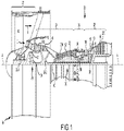
FIG. 1 illustrates an exemplary gas turbine engine, in accordance with various embodiments; -
FIG. 2 illustrates a low profile un-lensed NSMS probe, in accordance with various embodiments; -
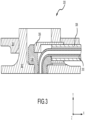
FIG. 3 illustrates a cross section of a low profile un-lensed NSMS probe, in accordance with various embodiments; -
FIG. 4 illustrates an expendable fiber arrangement holder for a low profile un-lensed NSMS probe, in accordance with various embodiments; -
FIG. 5A illustrates a cross section of a housing for a low profile un-lensed NSMS probe, in accordance with various embodiments; -
FIG. 5B illustrates a perspective view of a housing for a low profile un-lensed NSMS probe, in accordance with various embodiments; -
FIG. 5C illustrates a cross section of a housing for a low profile un-lensed NSMS probe, in accordance with various embodiments; -
FIG. 5D illustrates a top surface view of a housing for a low profile un-lensed NSMS probe, in accordance with various embodiments; -
FIG. 5E illustrates a perspective view of a housing for a low profile un-lensed NSMS probe, in accordance with various embodiments; -
FIG. 5F illustrates a cross section of a housing for a low profile un-lensed NSMS probe, in accordance with various embodiments; -
FIG. 6A illustrates a cap for a low profile un-lensed NSMS probe, in accordance with various embodiments; -
FIG. 6B illustrates a cap for a low profile un-lensed NSMS probe, in accordance with various embodiments; -
FIG. 7 illustrates a perspective cross section of a collet for a low profile un-lensed NSMS probe, in accordance with various embodiments; and -
FIG. 8 illustrates a method of manufacturing a low profile un-lensed NSMS probe, in accordance with various embodiments. - The detailed description of exemplary embodiments herein makes reference to the accompanying drawings, which show exemplary embodiments by way of illustration and their best mode. While these exemplary embodiments are described in sufficient detail to enable those skilled in the art to practice the disclosures, it should be understood that other embodiments may be realized and that logical, chemical, and mechanical changes may be made without departing from the spirit and scope of the disclosures. Thus, the detailed description herein is presented for purposes of illustration only and not of limitation. For example, the steps recited in any of the method or process descriptions may be executed in any order and are not necessarily limited to the order presented. Furthermore, any reference to singular includes plural embodiments, and any reference to more than one component or step may include a singular embodiment or step. Also, any reference to attached, fixed, connected or the like may include permanent, removable, temporary, partial, full and/or any other possible attachment option. Additionally, any reference to without contact (or similar phrases) may also include reduced contact or minimal contact.
- In various embodiments and with reference to
FIG. 1 , a gas turbine engine 20 is provided. Gas turbine engine 20 may be a two-spool turbofan that generally incorporates afan section 22, a compressor section 24, a combustor section 26 and a turbine section 28. In operation,fan section 22 can drive air along a bypass flow-path B while compressor section 24 can drive air for compression and communication into combustor section 26 then expansion through turbine section 28. Although depicted as a turbofan gas turbine engine 20 herein, it should be understood that the concepts described herein are not limited to use with turbofans as the teachings may be applied to other types of turbine engines including turbojet engines, a lowbypass turbofans, a high bypass turbofans, or any other gas turbine known to those skilled in the art. - Gas turbine engine 20 may generally comprise a low speed spool 30 and a high speed spool 32 mounted for rotation about an engine central longitudinal axis A-A' relative to an engine static structure 36 via one or more bearing systems 38 (shown as bearing system 38-1 and bearing system 38-2). It should be understood that various bearing systems 38 at various locations may alternatively or additionally be provided, including for example, bearing system 38, bearing system 38-1, and bearing system 38-2.
- Low speed spool 30 may generally comprise an inner shaft 40 that interconnects a fan 42, a low pressure (or first) compressor section 44 (also referred to a low pressure compressor) and a low pressure (or first) turbine section 46. Inner shaft 40 may be connected to fan 42 through a geared architecture 48 that can drive fan 42 at a lower speed than low speed spool 30. Geared architecture 48 may comprise a gear assembly 60 enclosed within a gear housing 62. Gear assembly 60 couples inner shaft 40 to a rotating fan structure. High speed spool 32 may comprise an outer shaft 50 that interconnects a high pressure compressor ("HPC") 52 (e.g., a second compressor section) and high pressure (or second) turbine section 54. A combustor 56 may be located between HPC 52 and high pressure turbine 54. A mid-turbine frame 57 of engine static structure 36 may be located generally between high pressure turbine 54 and low pressure turbine 46. Mid-turbine frame 57 may support one or more bearing systems 38 in turbine section 28. Inner shaft 40 and outer shaft 50 may be concentric and rotate via bearing systems 38 about the engine central longitudinal axis A-A', which is collinear with their longitudinal axes. As used herein, a "high pressure" compressor or turbine experiences a higher pressure than a corresponding "low pressure" compressor or turbine.
- The core airflow C may be compressed by low pressure compressor 44 then HPC 52, mixed and burned with fuel in combustor 56, then expanded over high pressure turbine 54 and low pressure turbine 46. Mid-turbine frame 57 includes airfoils 59 which are in the core airflow path. Low pressure turbine 46, and high pressure turbine 54 rotationally drive the respective low speed spool 30 and high speed spool 32 in response to the expansion.
- Gas turbine engine 20 may be, for example, a high-bypass geared aircraft engine. In various embodiments, the bypass ratio of gas turbine engine 20 may be greater than about six. In various embodiments, the bypass ratio of gas turbine engine 20 may be greater than ten. In various embodiments, geared architecture 48 may be an epicyclic gear train, such as a star gear system (sun gear in meshing engagement with a plurality of star gears supported by a carrier and in meshing engagement with a ring gear) or other gear system. Geared architecture 48 may have a gear reduction ratio of greater than about 2.3 and low pressure turbine 46 may have a pressure ratio that is greater than about 5. In various embodiments, the bypass ratio of gas turbine engine 20 is greater than about ten. In various embodiments, the diameter of fan 42 may be significantly larger than that of the low pressure compressor 44, and the low pressure turbine 46 may have a pressure ratio that is greater than about. Low pressure turbine 46 pressure ratio may be measured prior to inlet of low pressure turbine 46 as related to the pressure at the outlet of low pressure turbine 46 prior to an exhaust nozzle. It should be understood, however, that the above parameters are exemplary of various embodiments of a suitable geared architecture engine and that the present disclosure contemplates other gas turbine engines including direct drive turbofans.
- In various embodiments, the next generation of turbofan engines may be designed for higher efficiency which is associated with higher pressure ratios and higher temperatures in the HPC 52. These higher operating temperatures and pressure ratios may create operating environments that may cause thermal loads that are higher than the thermal loads encountered in conventional turbofan engines, which may shorten the operational life of current components.
- In various embodiments, HPC 52 may comprise alternating rows of rotating rotors and stationary stators. Stators may have a cantilevered configuration or a shrouded configuration. More specifically, a stator may comprise a stator vane, a casing support and a hub support. In this regard, a stator vane may be supported along an outer diameter by a casing support and along an inner diameter by a hub support. In contrast, a cantilevered stator may comprise a stator vane that is only retained and/or supported at the casing (e.g., along an outer diameter).
- In various embodiments, rotors may be configured to compress and spin a fluid flow. Stators may be configured to receive and straighten the fluid flow. In operation, the fluid flow discharged from the trailing edge of stators may be straightened (e.g., the flow may be directed in a substantially parallel path to the centerline of the engine and/or HPC) to increase and/or improve the efficiency of the engine and, more specifically, to achieve maximum and/or near maximum compression and efficiency when the straightened air is compressed and spun by rotor 64. In various embodiments, one or more low profile un-lensed NSMS probes 200 may be located within the geometries of gas turbine engine 20 structures such as, for example, a fan case of
fan section 22, a compressor case of compressor section 24, a combustor case of combustor section 26 and or the like. In various embodiments, a plurality of low profile un-lensed NSMS probes 200 may be located axially or circumferentially about a case. - With reference to
FIG. 2 , a low profile un-lensed NSMS probe 200 (hereinafter probe 200) is shown mounted to a case 202. Case 202 may comprise an outer gas path surface 206 and surround a rotating component of turbomachinery such asblade 216. A rub strip 204 comprising an inner gas path surface 214 may be coupled radially inward (relative to the axis of rotation of blade 216) of case 202 between the case 202 and theblade 216.Probe 200 is coupled atlip 210 of case 202 which extends inward (along the X-axis) within afirst bore 208 through outer gas path surface 206 of case 202 thereby forming an annular structure within thefirst bore 208. In various embodiments, a correspondingsecond bore 212 through inner gas path surface 214 of rub strip 204 may tend to facilitate coupling ofprobe 200 to case 202. - With additional reference to
FIG. 3 ,probe 200 is shown in cross section through the X-Y plane.Probe 200 compriseshousing 300 which retains an inner hypotube configured to contain a plurality of optical fibers.Housing 300 is disposed within a cavity formed by an annular wall ofinner collar 302.Housing 300 is sealed by acap 306 coupled to anouter hypotube 308 which shields theinner hypotube 310. Anouter collar 304 is coupled about the annular wall of theinner collar 302. - With additional reference to
FIG. 4 assembly of aprobe 200 may include preparing an expendablefiber arrangement holder 400. In various embodiments, expendablefiber arrangement holder 400 may comprise a metal or a metal alloy such as, for example brass, bronze, and/or the like. Expendablefiber arrangement holder 400 comprises an annularcylindrical structure 402 having a fiber channel 404 and a counterbore portion 406 extending intocounterbore end 408 oppositeopen end 410. A plurality ofoptical fibers 412 are inserted throughopen end 410 into fiber channel 404. An interference between the plurality of optical fibers and the wall of fiber channel 404 may tend to pack the plurality of optical fibers in a desirable geometic configuration. For example, seven fibers may be inserted into fiber channel 404 and may be arranged in a hexagonal packing configuration in response to the interference. In various embodiments, a hexagonal packing configuration may include a central transmit fiber T surrounded by six receive fibers R. In various embodiments, an epoxy 414 may be applied along the plurality ofoptical fibers 412 tending thereby to secure the plurality ofoptical fibers 412 in the desirable geometric configuration. In various embodiments, heat may be applied to promote the flow ofepoxy 414 into the fiber channel 404. - In various embodiments, excess optical fibers extending at
open end 410 may be cleaved andopen end 410 may be polished. In various embodiments, the fiber channel 404 may have a diameter of 0.0167 in [0.4241 mm] and the counterbore portion 406 may have an internal diameter of 0.036 in [0.914 mm]. In various embodiments, the annularcylindrical structure 402 may have an outer diameter of 0.050 in [1.27 mm] and the counterbore portion 406 may be recessed from the outer diameter by 0.005 in [0.127 mm]. In various embodiments, the annularcylindrical structure 402 may extend 0.080 in [2.032 mm] along the Y-axis. - With additional reference to
FIGs. 5A, 5B, and 5C housing 300 ofprobe 200 is shown in cross section and perspective.Housing 300 comprises abody 500 having atop surface 502 and abarrel portion 504 extending opposite thetop surface 502.Barrel portion 504 terminates atoptical face 506.Housing 300 includes afirst channel 510 which extends fromtop surface 502 along the Y-axis intobody 500 and asecond channel 512 within thefirst channel 510 and extending intobody 500 relatively below (along the Y-axis) thefirst channel 510. Thesecond channel 512 opens throughoptical face 506 at sensingaperture 508 and comprises aradiused portion 514.Inner hypotube 310 is inserted into thefirst channel 510 and into thesecond channel 512 and coupled at sensing aperture. In various embodiments,inner hypotube 310 may be coupled by one of brazing, shrink fitting, or welding. In various embodiments,inner hypotube 310 may extend relatively below (along the Y-axis) theoptical face 506 between 0.00 in [0.00 mm] and 0.025 in [0.635 mm], or may extend between 0.010 in [0.254 mm] and 0.020 in [0.508 mm]. - In various embodiments, the plurality of
optical fibers 412 may be drawn intoinner hypotube 310 and counterbore portion 406 of expendablefiber arrangement holder 400 may be inserted alongarrow 516 overinner hypotube 310. The expendablefiber arrangement holder 400 may be coupled atcounterbore end 408 to sensingaperture 508 andinner hypotube 310 may be filled withepoxy 414. In various embodiments, the epoxy may be partially cured and theinner hypotube 310 may be bent within thehousing 300 along the radiusedportion 514 as indicated byarrow 518 to match the radius. In various embodiments the bend may be between 45° and 90°. In various embodiments, the epoxy may be fully cured and the expendablefiber arrangement holder 400 may be polished flush withoptical face 506 where flush in this context means between 0.00 in [0.00 mm] and 0.025 in [0.635 mm] ofoptical face 506. - With additional reference to
FIGs. 5D, 5E, and 5F a housing 300' forprobe 200 is illustrated having features, geometries, construction, materials, manufacturing techniques, and/or internal components similar tohousing 300. Housing 300' includes abase portion 522 extending into thesecond channel 512 below (along the Y-axis) the radiusedportion 518. Thebase portion 522 has one or more of apurge port 524 opening from thesecond channel 512 through theoptical face 506 of thebarrel portion 504. - With additional reference to
FIGs. 6A and 6B ,cap 306 is shown coupled tohousing 300.Cap 306 comprises ahood portion 600 and asleeve portion 604.Outer hypotube 308 inserted intosleeve portion 604 and coupled to the sleeve portion atchamfer 608. Thecap 306 andouter hypotube 308 are slid (along arrow 610) overinner hypotube 310. Thehood portion 600 rests in the base of thefirst channel 510 and covers thefirst channel 510 and thesecond channel 512. Thehood portion 600 may be coupled to thetop surface 502 such as, for example, by a plurality of spot welds 602. In various embodiments, a cooling fluid may flow within theouter hypotube 308 and may be directed by thehood portion 600 into thefirst channel 510 and/or thesecond channel 512. In various embodiments, the coolant may exit thehousing 300 via thesensing aperture 508 or other exit path throughoptical face 506 such as, for example, purgeport 524. - With additional reference to
FIG. 7 ,inner collar 302 andouter collar 304 ofprobe 200 are shown in perspective cross section.Inner collar 302 comprises a first annular disk 702 having a first annulus 700.Annular wall 706 extends perpendicular to the plane of the first annular disk 702 about the first annulus 700 and definescavity 708 within.Annular wall 706 includes afirst cutout 710 and, in this regard, does not completely encircle first annulus 700.Outer collar 304 comprises a secondannular disk 704 having a second annulus defined by the outer diameter ofannular wall 706. The secondannular disk 704 comprises asecond cutout 712 of a width corresponding to thefirst cutout 710. In this regard, theannular wall 706 and the secondannular disk 704 may form a C-shape when viewed in plane. - In various embodiments and with combined reference to
FIGs. 2 ,5A , and6 ,inner collar 302 may be inserted throughsecond bore 212 withannular wall 706 relatively upward (along the Y-axis) andfirst surface 716 may be contacted withlip 210 and fixed in place withannular wall 706 protruding relatively abovelip 210.Outer collar 304 may be disposed aboutannular wall 706 withsecond surface 714 contactinglip 210 and thesecond cutout 712 may be aligned with thefirst cutout 710. Secondannular disk 704 ofouter collar 304 may be coupled about the second annulus to theannular wall 706 thereby coupling theinner collar 302 and theouter collar 304 to the case 202.Housing 300 may be disposed withincavity 708 withbarrel portion 504 inserted into first annulus 700 andcap 306 lying within thefirst cutout 710 and thesecond cutout 712. In various embodiments, thehousing 300 may be coupled attop surface 502 to the inner diameter of theannular wall 706 such as, for example, by a plurality of spot welds placed alongtop surface chamfer 520. In various embodiments, thefirst bore 208 and thesecond bore 212 may be filled by an epoxy and cured. In various embodiments, the second bore fill may be molded or match drilled to form an aperture in optical communication withsensing aperture 508 ofoptical face 506. - With additional reference to
FIG. 8 , amethod 800 of manufacturing a low profile un-lensed non-intrusive stress measurement system probe comprises inserting a plurality of optical fibers through a fiber channel of an expendable fiber arrangement holder and applying an epoxy to the plurality of optical fibers (step 802).Optical fibers 512 may be inserted into fiber channel 404 of expendablefiber arrangement holder 400 andepoxy 414 may be applied.Method 800 includes drawing the plurality of optical fibers into a first hypotube coupled at a sensing aperture of a housing and filling the first hypotube with the epoxy (step 804).Optical fibers 412 may be drawn intoinner hypotube 310 andinner hypotube 310 may be filled withepoxy 414. In various embodiments,epoxy 414 may be heated to promote flow ofepoxy 414 withininner hypotube 310.Method 800 includes coupling a counterbore end of the expendable fiber arrangement holder to the first hypotube at the sensing aperture (step 806). Counterbore portion 406 atcounterbore end 408 may be coupled about a portion ofinner hpyotube 310 protruding fromsensor aperture 508. -
Method 800 includes bending the first hypotube within the housing to match a radiused portion of the housing (step 808).Inner hypotube 310 may be bent to matchradiused portion 514 ofhousing 300. Step 808 may include curing the epoxy 414 in response to bending theinner hypotube 310.Method 800 includes polishing the expendable fiber arrangement holder flush with an optical face of the housing (step 810). Step 810 may include verifying theexpendable fiber holder 400 is securely coupled to theinner hypotube 310 such as, for example, by conducting a pull test. Expendablefiber arrangement holder 400 may be polished flush withoptical face 506 ofhousing 300 where flush in this context means between 0.00 in [0.00 mm] and 0.025 in [0.635 mm] ofoptical face 506. In various embodiments, the polishing process includes use of any of a fabricated polishing puck, 600 grit sand paper, 3 um Aluminum Oxide polishing paper, 3/10 um Aluminum Oxide polishing paper, and/or the like. In various embodiments a polishing machine may be used and a polishing head of the polishing machine may be configured between 50 and 100 RPM.
Claims (10)
- An un-lensed non-intrusive stress measurement system probe (200) for a gas turbine engine, comprising:a housing (300) comprising a first channel (510) and an optical face (506);a first tube (310) disposed within the first channel (510) and coupled at a sensing aperture (508) in the optical face (506); anda plurality of optical fibers (412) disposed within the first tube (310), wherein the first tube (310) executes a bend between 45° and 90° within the housing (300),characterized in that:
the housing (300) comprises a second channel (512) within the first channel (510), the second channel (512) comprising a radiused portion (514) and the first tube (310) bent along the radiused portion (514), and a cap (306) is coupled to the housing (300), the cap (306) comprising a hood (600) covering the first channel (510) and a sleeve portion (604) about the first tube (310), a second tube (308) disposed about the first tube (310) and inserted into the sleeve portion (604). - The probe of claim 1, wherein the plurality of optical fibers (412) comprises at least one of a transmit fiber and a receive fiber.
- The probe of claim 1 or 2, wherein the plurality of optical fibers (412) are arranged in an expendable fiber arrangement holder (400) coupled to the sensing aperture (508).
- The probe of any preceding claim, wherein the first tube (310) is filled with an epoxy.
- The probe of claim 1 or 2, wherein the plurality of optical fibers (412) are arranged in an expendable fiber arrangement holder (400) coupled to the sensing aperture (508), the first tube (310) is filled with an epoxy, the epoxy is cured and the expendable fiber arrangement holder (400) is polished flush with the optical face (506) in response to bending the first tube (310) along the radiused portion (514).
- The probe of any preceding claim, wherein the housing (300) is disposed within a cavity (708) defined by an annular wall (706) about a first annulus (700) of a first annular disk (702), the housing (300) comprising a barrel (504) inserted into the first annulus (700) of the first annular disk (702), and a second annular disk (704) comprising a second annulus defined by an outer diameter of the annular wall (706) is coupled at the second annulus to the annular wall (706).
- A gas turbine engine (20) comprising:a fan section (22);a compressor section (24) aft of the fan section (22) and configured to compress a gas;a combustor section (26) aft of the compressor section (24) and configured to combust the gas;a turbine section (28) aft of the combustor section (26) and configured to extract work from the gas;a case (202) about at least one of the fan section (22), the compressor section (24), the combustor section (26), or the turbine section (28); andthe probe (200) of any of claims 1 to 5, coupled to the case (202).
- The gas turbine engine of claim 7, wherein the housing (300) is disposed within a cavity (708) defined by an annular wall (706) about a first annulus (700) of a first annular disk (702), the housing (300) comprising a barrel (504) inserted into the first annulus (700) of the first annular disk (702), a second annular disk (704) comprising a second annulus defined by an outer diameter of the annular wall (706) is coupled at the second annulus to the annular wall (706).
- The gas turbine engine of claim 8, wherein the case (202) comprises a bore (208) having a lip (210) forming an annular structure within the bore (208), the first annular disk (702) has a first surface (716) in contact with the lip (210) and the second annular disk (704) has a second surface (714) in contact with the lip (210).
- A method (800) of manufacturing the un-lensed non-intrusive stress measurement system probe (200) of claim 1, the method comprising:inserting the plurality of optical fibers (412) through a fiber channel (404) of an expendable fiber arrangement holder (400) and applying an epoxy to the plurality of optical fibers (412);drawing the plurality of optical fibers (412) into the first tube (310) coupled at the sensing aperture (508) of the housing (300) and filling the first tube (310) with the epoxy;coupling a counterbore end (408) of the expendable fiber arrangement holder (400) to the first tube (310) at the sensing aperture (508);bending the first tube (310) within the housing (300) along the radiused portion (514) of the second channel (512); andpolishing the expendable fiber arrangement holder (400) flush with the optical face (506) of the housing (300),wherein the cap (306) is coupled to the housing (300).
Applications Claiming Priority (1)
| Application Number | Priority Date | Filing Date | Title |
|---|---|---|---|
| US16/132,128 US10794795B2 (en) | 2018-09-14 | 2018-09-14 | Low profile embedded non-intrusive stress measurement system probe |
Publications (2)
| Publication Number | Publication Date |
|---|---|
| EP3623790A1 EP3623790A1 (en) | 2020-03-18 |
| EP3623790B1 true EP3623790B1 (en) | 2023-03-08 |
Family
ID=67262208
Family Applications (1)
| Application Number | Title | Priority Date | Filing Date |
|---|---|---|---|
| EP19186112.9A Active EP3623790B1 (en) | 2018-09-14 | 2019-07-12 | Embedded non-intrusive stress measurement system probe |
Country Status (2)
| Country | Link |
|---|---|
| US (1) | US10794795B2 (en) |
| EP (1) | EP3623790B1 (en) |
Families Citing this family (6)
| Publication number | Priority date | Publication date | Assignee | Title |
|---|---|---|---|---|
| US11339679B1 (en) * | 2021-03-23 | 2022-05-24 | Pratt & Whitney Canada Corp. | Turbine probe heat shielding |
| US11428122B1 (en) * | 2021-03-23 | 2022-08-30 | Pratt & Whitney Canada Corp. | Thermal protection for a gas turbine engine probe |
| US11859503B1 (en) | 2022-06-30 | 2024-01-02 | Pratt & Whitney Canada Corp. | Probe heat shielding |
| US12455213B2 (en) | 2023-02-01 | 2025-10-28 | Rtx Corporation | Measurement system having a capacitance probe and an optical probe |
| CN116465526B (en) * | 2023-02-27 | 2025-06-13 | 中国科学院上海光学精密机械研究所 | Hot-end multi-channel probe based on fiber optic bundle |
| US12487425B2 (en) | 2023-03-21 | 2025-12-02 | Rtx Corporation | Coupling optical fibers and cooling fluid passages |
Family Cites Families (19)
| Publication number | Priority date | Publication date | Assignee | Title |
|---|---|---|---|---|
| US4666297A (en) * | 1985-11-14 | 1987-05-19 | United Technologies Corporation | Dual spectra optical pyrometer having an air pressure sensitive shutter |
| US4657386A (en) * | 1985-11-14 | 1987-04-14 | United Technologies Corporation | In-flight engine control optical pyrometer |
| US4708474A (en) * | 1985-11-14 | 1987-11-24 | United Technologies Corporation | Reflection corrected radiosity optical pyrometer |
| US4696544A (en) * | 1985-11-18 | 1987-09-29 | Olympus Corporation | Fiberscopic device for inspection of internal sections of construction, and method for using same |
| US8758333B2 (en) | 2006-04-04 | 2014-06-24 | The Spectranetics Corporation | Laser-assisted guidewire having a variable stiffness shaft |
| US8451459B2 (en) | 2008-10-31 | 2013-05-28 | General Electric Company | Method and system for inspecting blade tip clearance |
| US8256297B2 (en) | 2010-01-05 | 2012-09-04 | General Electric Company | Systems and methods for measuring turbine blade vibratory response |
| FR2990754B1 (en) | 2012-05-15 | 2015-06-05 | Snecma | DEVICE FOR MEASURING THE VIBRATORY AMPLITUDES OF THE AUBES IN A TURBOMACHINE |
| US20140064924A1 (en) * | 2012-08-30 | 2014-03-06 | Eli Cole Warren | Tip clearance probe for turbine applications |
| US9181818B2 (en) * | 2012-09-25 | 2015-11-10 | United Technologies Corporation | Thermally constrained high temperature optical fiber holder |
| US9297720B2 (en) | 2012-12-21 | 2016-03-29 | United Technologies Corporation | Gas turbine engine vane embedded beam interrupt optical tip-timing probe system |
| US9366586B2 (en) * | 2013-03-14 | 2016-06-14 | United Technologies Corporation | High temperature uncooled optical probe |
| WO2015069623A1 (en) * | 2013-11-08 | 2015-05-14 | United Technologies Corporation | Fiber grating temperature sensor |
| US9988929B2 (en) | 2015-01-06 | 2018-06-05 | United Technologies Corporation | Borescope plug for gas turbine engine |
| GB2541689B (en) | 2015-08-26 | 2020-04-15 | Rolls Royce Plc | Apparatus and methods for determining location of at least a part of an object |
| EP3327405A1 (en) | 2016-11-29 | 2018-05-30 | Siemens Aktiengesellschaft | Fibre optic sensor device |
| US10703854B2 (en) * | 2017-12-05 | 2020-07-07 | Raytheon Technologies Corporation | Epoxy formula for integral capacitance probe |
| US10557373B2 (en) * | 2017-12-05 | 2020-02-11 | United Technologies Corporation | Low profile embedded blade tip clearance probe assembly |
| US11686577B2 (en) * | 2018-09-20 | 2023-06-27 | Raytheon Technologies Corporation | Anti-rotation method for angled face cap probe |
-
2018
- 2018-09-14 US US16/132,128 patent/US10794795B2/en active Active
-
2019
- 2019-07-12 EP EP19186112.9A patent/EP3623790B1/en active Active
Also Published As
| Publication number | Publication date |
|---|---|
| EP3623790A1 (en) | 2020-03-18 |
| US10794795B2 (en) | 2020-10-06 |
| US20200088606A1 (en) | 2020-03-19 |
Similar Documents
| Publication | Publication Date | Title |
|---|---|---|
| US10794795B2 (en) | Low profile embedded non-intrusive stress measurement system probe | |
| EP3680455A1 (en) | Boas assemblies with axial support pins | |
| EP3495787B1 (en) | Low profile embedded blade tip clearance probe assembly | |
| EP3156606A2 (en) | Shrouds and methods for forming turbine components | |
| EP3683405A1 (en) | Frustic load transmission feature for composite structures | |
| US20120128468A1 (en) | Sensor assembly for use with a turbomachine and methods of assembling same | |
| EP3477047B1 (en) | Segmented structural links for coupled disk frequency tuning and corresponding gas turbine engine with such links | |
| EP3748134B1 (en) | Vane airfoil shapes for embedded members | |
| US12390894B2 (en) | Piston seal assembly guards and inserts for seal groove | |
| EP3730828B1 (en) | Dynamic sleeve seal fittings | |
| EP3543479A1 (en) | Floating bearing support assembly | |
| EP3708782B1 (en) | Boas and methods of making a boas having fatigue resistant cooling inlets | |
| US10641595B2 (en) | Low profile triaxial blade tip clearance probe assembly with driven guard | |
| EP3323998B1 (en) | Inner shroud segment and corresponding inner shroud and gas turbine motor | |
| EP3770476B1 (en) | Compliant jumper tube fitting | |
| US11215056B2 (en) | Thermally isolated rotor systems and methods | |
| EP3470685A1 (en) | Gap closing wearliner | |
| US20120171037A1 (en) | Probe assembly for use in turbine engines and method of assembling same |
Legal Events
| Date | Code | Title | Description |
|---|---|---|---|
| PUAI | Public reference made under article 153(3) epc to a published international application that has entered the european phase |
Free format text: ORIGINAL CODE: 0009012 |
|
| STAA | Information on the status of an ep patent application or granted ep patent |
Free format text: STATUS: THE APPLICATION HAS BEEN PUBLISHED |
|
| AK | Designated contracting states |
Kind code of ref document: A1 Designated state(s): AL AT BE BG CH CY CZ DE DK EE ES FI FR GB GR HR HU IE IS IT LI LT LU LV MC MK MT NL NO PL PT RO RS SE SI SK SM TR |
|
| AX | Request for extension of the european patent |
Extension state: BA ME |
|
| STAA | Information on the status of an ep patent application or granted ep patent |
Free format text: STATUS: REQUEST FOR EXAMINATION WAS MADE |
|
| 17P | Request for examination filed |
Effective date: 20200918 |
|
| RBV | Designated contracting states (corrected) |
Designated state(s): AL AT BE BG CH CY CZ DE DK EE ES FI FR GB GR HR HU IE IS IT LI LT LU LV MC MK MT NL NO PL PT RO RS SE SI SK SM TR |
|
| RAP1 | Party data changed (applicant data changed or rights of an application transferred) |
Owner name: RAYTHEON TECHNOLOGIES CORPORATION |
|
| STAA | Information on the status of an ep patent application or granted ep patent |
Free format text: STATUS: EXAMINATION IS IN PROGRESS |
|
| 17Q | First examination report despatched |
Effective date: 20220218 |
|
| REG | Reference to a national code |
Ref country code: DE Ref legal event code: R079 Ref document number: 602019026069 Country of ref document: DE Free format text: PREVIOUS MAIN CLASS: G01M0015140000 Ipc: G01H0001000000 |
|
| GRAP | Despatch of communication of intention to grant a patent |
Free format text: ORIGINAL CODE: EPIDOSNIGR1 |
|
| STAA | Information on the status of an ep patent application or granted ep patent |
Free format text: STATUS: GRANT OF PATENT IS INTENDED |
|
| RIC1 | Information provided on ipc code assigned before grant |
Ipc: G01M 5/00 20060101ALI20220831BHEP Ipc: G01H 9/00 20060101ALI20220831BHEP Ipc: G01M 15/14 20060101ALI20220831BHEP Ipc: F01D 21/00 20060101ALI20220831BHEP Ipc: G01D 11/24 20060101ALI20220831BHEP Ipc: G01M 15/00 20060101ALI20220831BHEP Ipc: G01H 1/00 20060101AFI20220831BHEP |
|
| INTG | Intention to grant announced |
Effective date: 20220915 |
|
| GRAS | Grant fee paid |
Free format text: ORIGINAL CODE: EPIDOSNIGR3 |
|
| GRAA | (expected) grant |
Free format text: ORIGINAL CODE: 0009210 |
|
| STAA | Information on the status of an ep patent application or granted ep patent |
Free format text: STATUS: THE PATENT HAS BEEN GRANTED |
|
| AK | Designated contracting states |
Kind code of ref document: B1 Designated state(s): AL AT BE BG CH CY CZ DE DK EE ES FI FR GB GR HR HU IE IS IT LI LT LU LV MC MK MT NL NO PL PT RO RS SE SI SK SM TR |
|
| REG | Reference to a national code |
Ref country code: CH Ref legal event code: EP Ref country code: AT Ref legal event code: REF Ref document number: 1552864 Country of ref document: AT Kind code of ref document: T Effective date: 20230315 |
|
| REG | Reference to a national code |
Ref country code: IE Ref legal event code: FG4D |
|
| REG | Reference to a national code |
Ref country code: DE Ref legal event code: R096 Ref document number: 602019026069 Country of ref document: DE |
|
| REG | Reference to a national code |
Ref country code: LT Ref legal event code: MG9D |
|
| P01 | Opt-out of the competence of the unified patent court (upc) registered |
Effective date: 20230521 |
|
| REG | Reference to a national code |
Ref country code: NL Ref legal event code: MP Effective date: 20230308 |
|
| PG25 | Lapsed in a contracting state [announced via postgrant information from national office to epo] |
Ref country code: RS Free format text: LAPSE BECAUSE OF FAILURE TO SUBMIT A TRANSLATION OF THE DESCRIPTION OR TO PAY THE FEE WITHIN THE PRESCRIBED TIME-LIMIT Effective date: 20230308 Ref country code: NO Free format text: LAPSE BECAUSE OF FAILURE TO SUBMIT A TRANSLATION OF THE DESCRIPTION OR TO PAY THE FEE WITHIN THE PRESCRIBED TIME-LIMIT Effective date: 20230608 Ref country code: LV Free format text: LAPSE BECAUSE OF FAILURE TO SUBMIT A TRANSLATION OF THE DESCRIPTION OR TO PAY THE FEE WITHIN THE PRESCRIBED TIME-LIMIT Effective date: 20230308 Ref country code: LT Free format text: LAPSE BECAUSE OF FAILURE TO SUBMIT A TRANSLATION OF THE DESCRIPTION OR TO PAY THE FEE WITHIN THE PRESCRIBED TIME-LIMIT Effective date: 20230308 Ref country code: HR Free format text: LAPSE BECAUSE OF FAILURE TO SUBMIT A TRANSLATION OF THE DESCRIPTION OR TO PAY THE FEE WITHIN THE PRESCRIBED TIME-LIMIT Effective date: 20230308 Ref country code: ES Free format text: LAPSE BECAUSE OF FAILURE TO SUBMIT A TRANSLATION OF THE DESCRIPTION OR TO PAY THE FEE WITHIN THE PRESCRIBED TIME-LIMIT Effective date: 20230308 |
|
| REG | Reference to a national code |
Ref country code: AT Ref legal event code: MK05 Ref document number: 1552864 Country of ref document: AT Kind code of ref document: T Effective date: 20230308 |
|
| PG25 | Lapsed in a contracting state [announced via postgrant information from national office to epo] |
Ref country code: SE Free format text: LAPSE BECAUSE OF FAILURE TO SUBMIT A TRANSLATION OF THE DESCRIPTION OR TO PAY THE FEE WITHIN THE PRESCRIBED TIME-LIMIT Effective date: 20230308 Ref country code: NL Free format text: LAPSE BECAUSE OF FAILURE TO SUBMIT A TRANSLATION OF THE DESCRIPTION OR TO PAY THE FEE WITHIN THE PRESCRIBED TIME-LIMIT Effective date: 20230308 Ref country code: GR Free format text: LAPSE BECAUSE OF FAILURE TO SUBMIT A TRANSLATION OF THE DESCRIPTION OR TO PAY THE FEE WITHIN THE PRESCRIBED TIME-LIMIT Effective date: 20230609 Ref country code: FI Free format text: LAPSE BECAUSE OF FAILURE TO SUBMIT A TRANSLATION OF THE DESCRIPTION OR TO PAY THE FEE WITHIN THE PRESCRIBED TIME-LIMIT Effective date: 20230308 |
|
| PG25 | Lapsed in a contracting state [announced via postgrant information from national office to epo] |
Ref country code: SM Free format text: LAPSE BECAUSE OF FAILURE TO SUBMIT A TRANSLATION OF THE DESCRIPTION OR TO PAY THE FEE WITHIN THE PRESCRIBED TIME-LIMIT Effective date: 20230308 Ref country code: RO Free format text: LAPSE BECAUSE OF FAILURE TO SUBMIT A TRANSLATION OF THE DESCRIPTION OR TO PAY THE FEE WITHIN THE PRESCRIBED TIME-LIMIT Effective date: 20230308 Ref country code: PT Free format text: LAPSE BECAUSE OF FAILURE TO SUBMIT A TRANSLATION OF THE DESCRIPTION OR TO PAY THE FEE WITHIN THE PRESCRIBED TIME-LIMIT Effective date: 20230710 Ref country code: EE Free format text: LAPSE BECAUSE OF FAILURE TO SUBMIT A TRANSLATION OF THE DESCRIPTION OR TO PAY THE FEE WITHIN THE PRESCRIBED TIME-LIMIT Effective date: 20230308 Ref country code: CZ Free format text: LAPSE BECAUSE OF FAILURE TO SUBMIT A TRANSLATION OF THE DESCRIPTION OR TO PAY THE FEE WITHIN THE PRESCRIBED TIME-LIMIT Effective date: 20230308 Ref country code: AT Free format text: LAPSE BECAUSE OF FAILURE TO SUBMIT A TRANSLATION OF THE DESCRIPTION OR TO PAY THE FEE WITHIN THE PRESCRIBED TIME-LIMIT Effective date: 20230308 |
|
| RAP4 | Party data changed (patent owner data changed or rights of a patent transferred) |
Owner name: RTX CORPORATION |
|
| PG25 | Lapsed in a contracting state [announced via postgrant information from national office to epo] |
Ref country code: SK Free format text: LAPSE BECAUSE OF FAILURE TO SUBMIT A TRANSLATION OF THE DESCRIPTION OR TO PAY THE FEE WITHIN THE PRESCRIBED TIME-LIMIT Effective date: 20230308 Ref country code: PL Free format text: LAPSE BECAUSE OF FAILURE TO SUBMIT A TRANSLATION OF THE DESCRIPTION OR TO PAY THE FEE WITHIN THE PRESCRIBED TIME-LIMIT Effective date: 20230308 Ref country code: IS Free format text: LAPSE BECAUSE OF FAILURE TO SUBMIT A TRANSLATION OF THE DESCRIPTION OR TO PAY THE FEE WITHIN THE PRESCRIBED TIME-LIMIT Effective date: 20230708 |
|
| REG | Reference to a national code |
Ref country code: DE Ref legal event code: R097 Ref document number: 602019026069 Country of ref document: DE |
|
| PLBE | No opposition filed within time limit |
Free format text: ORIGINAL CODE: 0009261 |
|
| STAA | Information on the status of an ep patent application or granted ep patent |
Free format text: STATUS: NO OPPOSITION FILED WITHIN TIME LIMIT |
|
| PG25 | Lapsed in a contracting state [announced via postgrant information from national office to epo] |
Ref country code: SI Free format text: LAPSE BECAUSE OF FAILURE TO SUBMIT A TRANSLATION OF THE DESCRIPTION OR TO PAY THE FEE WITHIN THE PRESCRIBED TIME-LIMIT Effective date: 20230308 Ref country code: DK Free format text: LAPSE BECAUSE OF FAILURE TO SUBMIT A TRANSLATION OF THE DESCRIPTION OR TO PAY THE FEE WITHIN THE PRESCRIBED TIME-LIMIT Effective date: 20230308 |
|
| 26N | No opposition filed |
Effective date: 20231211 |
|
| PG25 | Lapsed in a contracting state [announced via postgrant information from national office to epo] |
Ref country code: MC Free format text: LAPSE BECAUSE OF FAILURE TO SUBMIT A TRANSLATION OF THE DESCRIPTION OR TO PAY THE FEE WITHIN THE PRESCRIBED TIME-LIMIT Effective date: 20230308 |
|
| PG25 | Lapsed in a contracting state [announced via postgrant information from national office to epo] |
Ref country code: MC Free format text: LAPSE BECAUSE OF FAILURE TO SUBMIT A TRANSLATION OF THE DESCRIPTION OR TO PAY THE FEE WITHIN THE PRESCRIBED TIME-LIMIT Effective date: 20230308 |
|
| REG | Reference to a national code |
Ref country code: CH Ref legal event code: PL |
|
| REG | Reference to a national code |
Ref country code: BE Ref legal event code: MM Effective date: 20230731 |
|
| PG25 | Lapsed in a contracting state [announced via postgrant information from national office to epo] |
Ref country code: LU Free format text: LAPSE BECAUSE OF NON-PAYMENT OF DUE FEES Effective date: 20230712 |
|
| PG25 | Lapsed in a contracting state [announced via postgrant information from national office to epo] |
Ref country code: LU Free format text: LAPSE BECAUSE OF NON-PAYMENT OF DUE FEES Effective date: 20230712 |
|
| REG | Reference to a national code |
Ref country code: IE Ref legal event code: MM4A |
|
| PG25 | Lapsed in a contracting state [announced via postgrant information from national office to epo] |
Ref country code: CH Free format text: LAPSE BECAUSE OF NON-PAYMENT OF DUE FEES Effective date: 20230731 |
|
| PG25 | Lapsed in a contracting state [announced via postgrant information from national office to epo] |
Ref country code: IT Free format text: LAPSE BECAUSE OF FAILURE TO SUBMIT A TRANSLATION OF THE DESCRIPTION OR TO PAY THE FEE WITHIN THE PRESCRIBED TIME-LIMIT Effective date: 20230308 Ref country code: BE Free format text: LAPSE BECAUSE OF NON-PAYMENT OF DUE FEES Effective date: 20230731 |
|
| PG25 | Lapsed in a contracting state [announced via postgrant information from national office to epo] |
Ref country code: IE Free format text: LAPSE BECAUSE OF NON-PAYMENT OF DUE FEES Effective date: 20230712 |
|
| PG25 | Lapsed in a contracting state [announced via postgrant information from national office to epo] |
Ref country code: IE Free format text: LAPSE BECAUSE OF NON-PAYMENT OF DUE FEES Effective date: 20230712 |
|
| PG25 | Lapsed in a contracting state [announced via postgrant information from national office to epo] |
Ref country code: BG Free format text: LAPSE BECAUSE OF FAILURE TO SUBMIT A TRANSLATION OF THE DESCRIPTION OR TO PAY THE FEE WITHIN THE PRESCRIBED TIME-LIMIT Effective date: 20230308 |
|
| PG25 | Lapsed in a contracting state [announced via postgrant information from national office to epo] |
Ref country code: BG Free format text: LAPSE BECAUSE OF FAILURE TO SUBMIT A TRANSLATION OF THE DESCRIPTION OR TO PAY THE FEE WITHIN THE PRESCRIBED TIME-LIMIT Effective date: 20230308 |
|
| PGFP | Annual fee paid to national office [announced via postgrant information from national office to epo] |
Ref country code: GB Payment date: 20250619 Year of fee payment: 7 |
|
| PGFP | Annual fee paid to national office [announced via postgrant information from national office to epo] |
Ref country code: FR Payment date: 20250620 Year of fee payment: 7 |
|
| PG25 | Lapsed in a contracting state [announced via postgrant information from national office to epo] |
Ref country code: CY Free format text: LAPSE BECAUSE OF FAILURE TO SUBMIT A TRANSLATION OF THE DESCRIPTION OR TO PAY THE FEE WITHIN THE PRESCRIBED TIME-LIMIT; INVALID AB INITIO Effective date: 20190712 |
|
| PG25 | Lapsed in a contracting state [announced via postgrant information from national office to epo] |
Ref country code: HU Free format text: LAPSE BECAUSE OF FAILURE TO SUBMIT A TRANSLATION OF THE DESCRIPTION OR TO PAY THE FEE WITHIN THE PRESCRIBED TIME-LIMIT; INVALID AB INITIO Effective date: 20190712 |
|
| REG | Reference to a national code |
Ref country code: DE Ref legal event code: R081 Ref document number: 602019026069 Country of ref document: DE Owner name: RTX CORPORATION (N.D.GES.D. STAATES DELAWARE),, US Free format text: FORMER OWNER: RAYTHEON TECHNOLOGIES CORPORATION, FARMINGTON, CT, US |
|
| PGFP | Annual fee paid to national office [announced via postgrant information from national office to epo] |
Ref country code: DE Payment date: 20250620 Year of fee payment: 7 |
|
| PG25 | Lapsed in a contracting state [announced via postgrant information from national office to epo] |
Ref country code: TR Free format text: LAPSE BECAUSE OF FAILURE TO SUBMIT A TRANSLATION OF THE DESCRIPTION OR TO PAY THE FEE WITHIN THE PRESCRIBED TIME-LIMIT Effective date: 20230308 |