EP3623584A1 - Set screw gap control between fixed and variable vanes - Google Patents
Set screw gap control between fixed and variable vanes Download PDFInfo
- Publication number
- EP3623584A1 EP3623584A1 EP19186163.2A EP19186163A EP3623584A1 EP 3623584 A1 EP3623584 A1 EP 3623584A1 EP 19186163 A EP19186163 A EP 19186163A EP 3623584 A1 EP3623584 A1 EP 3623584A1
- Authority
- EP
- European Patent Office
- Prior art keywords
- vane
- recess
- wall
- set screw
- opening
- Prior art date
- Legal status (The legal status is an assumption and is not a legal conclusion. Google has not performed a legal analysis and makes no representation as to the accuracy of the status listed.)
- Granted
Links
Images




Classifications
-
- F—MECHANICAL ENGINEERING; LIGHTING; HEATING; WEAPONS; BLASTING
- F01—MACHINES OR ENGINES IN GENERAL; ENGINE PLANTS IN GENERAL; STEAM ENGINES
- F01D—NON-POSITIVE DISPLACEMENT MACHINES OR ENGINES, e.g. STEAM TURBINES
- F01D17/00—Regulating or controlling by varying flow
- F01D17/10—Final actuators
- F01D17/12—Final actuators arranged in stator parts
- F01D17/14—Final actuators arranged in stator parts varying effective cross-sectional area of nozzles or guide conduits
- F01D17/16—Final actuators arranged in stator parts varying effective cross-sectional area of nozzles or guide conduits by means of nozzle vanes
- F01D17/162—Final actuators arranged in stator parts varying effective cross-sectional area of nozzles or guide conduits by means of nozzle vanes for axial flow, i.e. the vanes turning around axes which are essentially perpendicular to the rotor centre line
-
- F—MECHANICAL ENGINEERING; LIGHTING; HEATING; WEAPONS; BLASTING
- F01—MACHINES OR ENGINES IN GENERAL; ENGINE PLANTS IN GENERAL; STEAM ENGINES
- F01D—NON-POSITIVE DISPLACEMENT MACHINES OR ENGINES, e.g. STEAM TURBINES
- F01D5/00—Blades; Blade-carrying members; Heating, heat-insulating, cooling or antivibration means on the blades or the members
- F01D5/12—Blades
- F01D5/14—Form or construction
- F01D5/141—Shape, i.e. outer, aerodynamic form
- F01D5/146—Shape, i.e. outer, aerodynamic form of blades with tandem configuration, split blades or slotted blades
-
- F—MECHANICAL ENGINEERING; LIGHTING; HEATING; WEAPONS; BLASTING
- F01—MACHINES OR ENGINES IN GENERAL; ENGINE PLANTS IN GENERAL; STEAM ENGINES
- F01D—NON-POSITIVE DISPLACEMENT MACHINES OR ENGINES, e.g. STEAM TURBINES
- F01D9/00—Stators
- F01D9/02—Nozzles; Nozzle boxes; Stator blades; Guide conduits, e.g. individual nozzles
- F01D9/04—Nozzles; Nozzle boxes; Stator blades; Guide conduits, e.g. individual nozzles forming ring or sector
- F01D9/041—Nozzles; Nozzle boxes; Stator blades; Guide conduits, e.g. individual nozzles forming ring or sector using blades
-
- F—MECHANICAL ENGINEERING; LIGHTING; HEATING; WEAPONS; BLASTING
- F01—MACHINES OR ENGINES IN GENERAL; ENGINE PLANTS IN GENERAL; STEAM ENGINES
- F01D—NON-POSITIVE DISPLACEMENT MACHINES OR ENGINES, e.g. STEAM TURBINES
- F01D9/00—Stators
- F01D9/02—Nozzles; Nozzle boxes; Stator blades; Guide conduits, e.g. individual nozzles
- F01D9/04—Nozzles; Nozzle boxes; Stator blades; Guide conduits, e.g. individual nozzles forming ring or sector
- F01D9/042—Nozzles; Nozzle boxes; Stator blades; Guide conduits, e.g. individual nozzles forming ring or sector fixing blades to stators
-
- F—MECHANICAL ENGINEERING; LIGHTING; HEATING; WEAPONS; BLASTING
- F05—INDEXING SCHEMES RELATING TO ENGINES OR PUMPS IN VARIOUS SUBCLASSES OF CLASSES F01-F04
- F05D—INDEXING SCHEME FOR ASPECTS RELATING TO NON-POSITIVE-DISPLACEMENT MACHINES OR ENGINES, GAS-TURBINES OR JET-PROPULSION PLANTS
- F05D2230/00—Manufacture
- F05D2230/60—Assembly methods
-
- F—MECHANICAL ENGINEERING; LIGHTING; HEATING; WEAPONS; BLASTING
- F05—INDEXING SCHEMES RELATING TO ENGINES OR PUMPS IN VARIOUS SUBCLASSES OF CLASSES F01-F04
- F05D—INDEXING SCHEME FOR ASPECTS RELATING TO NON-POSITIVE-DISPLACEMENT MACHINES OR ENGINES, GAS-TURBINES OR JET-PROPULSION PLANTS
- F05D2230/00—Manufacture
- F05D2230/60—Assembly methods
- F05D2230/64—Assembly methods using positioning or alignment devices for aligning or centring, e.g. pins
-
- F—MECHANICAL ENGINEERING; LIGHTING; HEATING; WEAPONS; BLASTING
- F05—INDEXING SCHEMES RELATING TO ENGINES OR PUMPS IN VARIOUS SUBCLASSES OF CLASSES F01-F04
- F05D—INDEXING SCHEME FOR ASPECTS RELATING TO NON-POSITIVE-DISPLACEMENT MACHINES OR ENGINES, GAS-TURBINES OR JET-PROPULSION PLANTS
- F05D2240/00—Components
- F05D2240/10—Stators
- F05D2240/12—Fluid guiding means, e.g. vanes
-
- F—MECHANICAL ENGINEERING; LIGHTING; HEATING; WEAPONS; BLASTING
- F05—INDEXING SCHEMES RELATING TO ENGINES OR PUMPS IN VARIOUS SUBCLASSES OF CLASSES F01-F04
- F05D—INDEXING SCHEME FOR ASPECTS RELATING TO NON-POSITIVE-DISPLACEMENT MACHINES OR ENGINES, GAS-TURBINES OR JET-PROPULSION PLANTS
- F05D2240/00—Components
- F05D2240/80—Platforms for stationary or moving blades
-
- F—MECHANICAL ENGINEERING; LIGHTING; HEATING; WEAPONS; BLASTING
- F05—INDEXING SCHEMES RELATING TO ENGINES OR PUMPS IN VARIOUS SUBCLASSES OF CLASSES F01-F04
- F05D—INDEXING SCHEME FOR ASPECTS RELATING TO NON-POSITIVE-DISPLACEMENT MACHINES OR ENGINES, GAS-TURBINES OR JET-PROPULSION PLANTS
- F05D2260/00—Function
- F05D2260/30—Retaining components in desired mutual position
-
- Y—GENERAL TAGGING OF NEW TECHNOLOGICAL DEVELOPMENTS; GENERAL TAGGING OF CROSS-SECTIONAL TECHNOLOGIES SPANNING OVER SEVERAL SECTIONS OF THE IPC; TECHNICAL SUBJECTS COVERED BY FORMER USPC CROSS-REFERENCE ART COLLECTIONS [XRACs] AND DIGESTS
- Y02—TECHNOLOGIES OR APPLICATIONS FOR MITIGATION OR ADAPTATION AGAINST CLIMATE CHANGE
- Y02T—CLIMATE CHANGE MITIGATION TECHNOLOGIES RELATED TO TRANSPORTATION
- Y02T50/00—Aeronautics or air transport
- Y02T50/60—Efficient propulsion technologies, e.g. for aircraft
Definitions
- variable vanes for variable vane actuation systems of gas turbine engines and, more particularly, to a method and apparatus for adjusting the distance between variable vanes and blades of a gas turbine engine.
- a gas turbine engine typically includes a fan section, a compressor section, a combustor section and a turbine section. Air entering the compressor section is compressed and delivered into the combustion section where it is mixed with fuel and ignited to generate a high-speed exhaust gas flow. The high-speed exhaust gas flow expands through the turbine section to drive the compressor and the fan section.
- the compressor section typically includes low and high pressure compressors, and the turbine section includes low and high pressure turbines.
- Vanes are provided between rotating blades in the compressor and turbine sections. Moreover, vanes are also provided in the fan section. In some instances the vanes are movable to tailor flows to engine operating conditions. Variable vanes are mounted about a pivot and are attached to an arm that is in turn actuated to adjust each of the vanes of a stage. A specific rotation of the vane is required to assure that each vane in a stage is adjusted as desired to provide the desired engine operation.
- the vanes may be adjacent to rotating blades and the interactions of the airflow between the vanes and the rotating blades may vary aerodynamic characteristics of airflow through the engine.
- variable vane adjustment system for a gas turbine engine.
- the variable vane adjustment system including: a vane platform having a recess, a vane opening within the recess, and a set screw opening originating at a first wall of the recess and extending into the vane platform; a trunnion carrier having a base portion located at least partially within the recess, a bushing attached to the base portion, and an orifice that extends through the base portion and the bushing, wherein the orifice is aligned with the vane opening; a variable vane having a vane stem, the vane stem extending through the vane opening of the vane platform and the orifice of the trunnion carrier; and a set screw located at least partially within the set screw opening, the set screw being configured to longitudinally traverse the set screw opening as the set screw is rotated, wherein the set screw is configured to project into the recess and impact the base portion of the trunnion carrier to
- further embodiments may include that the first wall of the recess is an aft wall.
- further embodiments may include that the first wall of the recess is a forward wall.
- further embodiments may include that the set screw opening extends from the first wall of the recess to an aft side of the vane platform.
- further embodiments may include that the set screw opening extends from the first wall of the recess to a forward side of the vane platform.
- further embodiments may include: a biasing mechanism located at a second wall of the recess opposite the first wall, the biasing mechanism at least partially projecting into the recess.
- further embodiments may include that the second wall of the recess is an aft wall.
- further embodiments may include that the second wall of the recess is a forward wall.
- biasing mechanism is located at least partially within a biasing mechanism opening originating at the second wall and extending into the vane platform.
- biasing mechanism is a spring
- further embodiments may include that the biasing mechanism is attached to the second wall.
- a method of assembling a variable vane adjustment system for a gas turbine engine including: inserting a set screw at least partially into a set screw opening originating at a first wall of a recess within a vane platform, the set screw opening extending from the first wall into the vane platform, wherein the set screw is configured to longitudinally traverse the set screw opening as the set screw is rotated; inserting a trunnion carrier at least partially into the recess of the vane platform, the trunnion carrier having a base portion located at least partially within the recess, a bushing attached to the base portion, and an orifice that extends through the base portion and the bushing; wherein the base portion is configured to fit at least partially within the recess of the vane platform; aligning the orifice of the trunnion carrier with a vane opening located within the recess of the vane platform; inserting a vane stem of a variable vane through the vane opening
- further embodiments may include that the first wall of the recess is an aft wall.
- further embodiments may include that the first wall of the recess is a forward wall.
- further embodiments may include that the set screw opening extends from the first wall of the recess to an aft side of the vane platform.
- further embodiments may include that the set screw opening extends from the first wall of the recess to a forward side of the vane platform.
- further embodiments may include: operably connecting a biasing mechanism to the vane platform, wherein the biasing mechanism is located at a second wall of the recess opposite the first wall and at least partially projects into the recess.
- further embodiments may include that the second wall of the recess is an aft wall.
- further embodiments may include that the second wall of the recess is a forward wall.
- biasing mechanism is located at least partially within a biasing mechanism opening originating at the second wall and extending into the vane platform.
- FIG. 1 schematically illustrates a gas turbine engine 20.
- the gas turbine engine 20 is disclosed herein as a two-spool turbofan that generally incorporates a fan section 22, a compressor section 24, a combustor section 26 and a turbine section 28.
- Alternative engines might include an augmentor section (not shown) among other systems or features.
- the fan section 22 drives air along a bypass flow path B in a bypass duct, while the compressor section 24 drives air along a core flow path C for compression and communication into the combustor section 26 then expansion through the turbine section 28.
- the exemplary engine 20 generally includes a low speed spool 30 and a high speed spool 32 mounted for rotation about an engine central longitudinal axis A relative to an engine static structure 36 via several bearing systems 38. It should be understood that various bearing systems 38 at various locations may alternatively or additionally be provided, and the location of bearing systems 38 may be varied as appropriate to the application.
- the low speed spool 30 generally includes an inner shaft 40 that interconnects a fan 42, a low pressure compressor 44 and a low pressure turbine 46.
- the inner shaft 40 is connected to the fan 42 through a speed change mechanism, which in exemplary gas turbine engine 20 is illustrated as a geared architecture 48 to drive the fan 42 at a lower speed than the low speed spool 30.
- the high speed spool 32 includes an outer shaft 50 that interconnects a high pressure compressor 52 and high pressure turbine 54.
- a combustor 56 is arranged in exemplary gas turbine 20 between the high pressure compressor 52 and the high pressure turbine 54.
- An engine static structure 36 is arranged generally between the high pressure turbine 54 and the low pressure turbine 46.
- the engine static structure 36 further supports bearing systems 38 in the turbine section 28.
- the inner shaft 40 and the outer shaft 50 are concentric and rotate via bearing systems 38 about the engine central longitudinal axis A which is collinear with their longitudinal axes.
- each of the positions of the fan section 22, compressor section 24, combustor section 26, turbine section 28, and fan drive gear system 48 may be varied.
- gear system 48 may be located aft of combustor section 26 or even aft of turbine section 28, and fan section 22 may be positioned forward or aft of the location of gear system 48.
- the engine 20 in one example is a high-bypass geared aircraft engine.
- the engine 20 bypass ratio is greater than about six (6), with an example embodiment being greater than about ten (10)
- the geared architecture 48 is an epicyclic gear train, such as a planetary gear system or other gear system, with a gear reduction ratio of greater than about 2.3
- the low pressure turbine 46 has a pressure ratio that is greater than about five.
- the engine 20 bypass ratio is greater than about ten (10:1)
- the fan diameter is significantly larger than that of the low pressure compressor 44
- the low pressure turbine 46 has a pressure ratio that is greater than about five 5:1.
- Low pressure turbine 46 pressure ratio is pressure measured prior to inlet of low pressure turbine 46 as related to the pressure at the outlet of the low pressure turbine 46 prior to an exhaust nozzle.
- the geared architecture 48 may be an epicycle gear train, such as a planetary gear system or other gear system, with a gear reduction ratio of greater than about 2.3:1. It should be understood, however, that the above parameters are only exemplary of one embodiment of a geared architecture engine and that the present disclosure is applicable to other gas turbine engines including direct drive turbofans.
- the fan section 22 of the engine 20 is designed for a particular flight condition--typically cruise at about 0.8Mach and about 35,000 feet (10,668 meters).
- 'TSFC' Thrust Specific Fuel Consumption
- Low fan pressure ratio is the pressure ratio across the fan blade alone, without a Fan Exit Guide Vane (“FEGV”) system.
- the low fan pressure ratio as disclosed herein according to one non-limiting embodiment is less than about 1.45.
- Low corrected fan tip speed is the actual fan tip speed in ft/sec divided by an industry standard temperature correction of [(Tram °R)/(518.7 °R)] 0.5 .
- the "Low corrected fan tip speed” as disclosed herein according to one non-limiting embodiment is less than about 1150 ft/second (350.5 m/sec).
- FIG. 2 illustrates a cross-sectional view of a portion of the compressor section 24, which may reside in the low pressure compressor 44 or the high pressure compressor 52. Further, while the embodiments disclosed herein are described in the context of the compressor section 24, the present disclosure may be applied to the turbine section 28.
- the compressor section 24 includes a compressor rotor 100 that is rotatable about the engine central longitudinal axis A and includes one or more stages or circumferentially extending rows of blades 102.
- the compressor section 24 further includes one or more vane stages 110 each including a circumferentially extending row of variable vanes 104, in an axially alternating arrangement with the blades 102.
- the variable vanes 104 and blades 102 are disposed inside a compressor case 106.
- variable-pitch vane stages 110 are variable-pitch vane stages 110 such that each variable vane 104 is rotatable about a vane axis 112.
- the blades 102 rotate circumferentially around the engine central longitudinal axis A.
- the blades 102 do not rotate around a blade axis 122.
- Due to the rotatable nature of the variable vane 104 about the vane axis 112 a distance D1 measured between the variable vane 104 and the blade 102 may vary.
- the distance D1 may be measured between the leading edge 101 of the blade 102 and the trailing edge 103 of the variable vane 104.
- the distance D1 may also be measured between the trailing edge 105 of the blade 102 and the leading edge 107 of the variable vane 104.
- each variable vane 104 includes a vane stem 116 extending through a vane opening 118 in the compressor case 106.
- a vane platform 210 may be attached to the compressor case 106 (see FIGs. 3 and 4 ), as discussed further below.
- the vane platform 210 is a removable platform that may be integral to the fixed vane 102 that is installed into the compressor case 106.
- each vane stem 116 is connected to synchronization ring 114 via a vane arm 120. Rotation of the vane stem 116 by the vane arm 120 rotates the variable vane 104.
- FIG. 3 illustrates a view of variable vane adjustment system 200 for a variable vane 104, according to an embodiment of the present disclosure.
- the variable vane adjustment system 200 includes a trunnion carrier 220, as shown in FIG. 3 .
- the trunnion carrier 220 includes a base portion 221 that is configured to fit within a recess 180 located within the vane platform 210.
- the base portion 221 and the recess 180 may have complimentary shapes, such that the base portions 221 fits into the recess 180 like a puzzle piece.
- the base portion 221 and the recess 180 may each have a square shape.
- the recess 180 may have four side walls 182 and a bottom base 184.
- the square shape of the base portion 221 is smaller than the square shape of the recess 180, so that the base portion 221 will fit within the recess 180. There is some room (i.e., play) for the base portion 221 to move within the recess 180 in the forward direction X1 and the aft direction X2.
- the fit of the base portion 221 within the recess 180 restricts motion of the base portion 221 in a direction perpendicular to the forward direction X1 and the aft direction X2, such that, the base portion 221 may exhibit little to no motion in the direction perpendicular to the forward direction X1 and the aft direction X2.
- the trunnion carrier 220 also includes an orifice 224 that extends through the base portion 221 and the bushing 222.
- the vane stem 116 of the variable vane 104 extends through a vane opening 118 in the vane platform 210, and through the orifice 224 of the trunnion carrier 220.
- the variable vane adjustment system 200 includes a set screw 240 that is inserted into a set screw opening 242 from an aft side 172 of the vane platform 210.
- the set screw opening 242 may extend from the aft side 172 of the vane platform 210 to the recess 180 within the vane platform 210.
- the set screw opening 242 may also extend from a forward side 174 of the vane platform 210 to the recess 180 of the vane platform 210.
- the set screw opening 242 may be a blind hole extending from an aft wall 182a or a forward wall 182b into the vane platform 210.
- the set screw 240 is configured to project into the recess 180 and impact the base portion 221 of the trunnion carrier 220 to move the trunnion carrier 220 and the variable vane 104 in a forward direction X1 or an aft direction X2.
- the screw 240 projects into the recess 180 a projection distance D2 as measured away from a wall 182 of the recess 180. As shown in FIG. 3 , the screw 240 may project into the recess 180 away from an aft wall 182a of the recess 180.
- FIG. 4 illustrates a view of variable vane adjustment system 200 for a variable vane 104, according to an embodiment of the present disclosure.
- the variable vane adjustment system 200 includes a trunnion carrier 220, as shown in FIG. 4 .
- the trunnion carrier 220 includes a base portion 221 that is configured to fit within a recess 180 located within the vane platform 210.
- the base portion 221 and the recess 180 may have complimentary shapes, such that the base portions 221 fits into the recess 180 like a puzzle piece.
- the base portion 221 and the recess 180 may each have a square shape.
- the recess 180 may have four side walls 182 and a bottom base 184.
- the square shape of the base portion 221 is smaller than the square shape of the recess 180, so that the base portion 221 will fit within the recess 180. There is some room (i.e., play) for the base portion 221 to move within the recess 180 in the forward direction X1 and the aft direction X2.
- the fit of the base portion 221 within the recess 180 restricts motion of the base portion 221 in a direction perpendicular to the forward direction X1 and the aft direction X2, such that, the base portion 221 may exhibit little to no motion in the direction perpendicular to the forward direction X1 and the aft direction X2.
- the trunnion carrier 220 also includes an orifice 224 that extends through the base portion 221 and the bushing 222.
- the vane stem 116 of the variable vane 104 extends through a vane opening 118 in the vane platform 210, and through the orifice 224 of the trunnion carrier 220.
- the variable vane adjustment system 200 includes a set screw 240 that is inserted into a set screw opening 244 from a forward side 174 of the vane platform 210.
- the set screw opening 244 may extend from the forward side 174 of the vane platform 210 to the recess 180 within the vane platform 210. In other embodiments, the set screw opening 244 may also extend from an aft side 172 of the vane platform 210 to the recess 180 of the vane platform 210. In another embodiment, the set screw opening 244 may be a blind hole extending from an aft wall 182a or a forward wall 182b into the vane platform 210.
- the set screw 240 is configured to project into the recess 180 and impact the base portion 221 of the trunnion carrier 220 to move the trunnion carrier 220 and the variable vane 104 in a forward direction X1 or an aft direction X2.
- the screw 240 projects into the recess 180 a projection distance D2 as measured away from a wall 182 of the recess 180. As shown in FIG. 4 , the screw 240 may project into the recess 180 away from a forward wall 182b of the recess 180.
- a biasing mechanism 290 may be located at an aft wall 182a opposite the forward wall 182b of the recess 180.
- the biasing mechanism 290 is a spring.
- the biasing mechanism 290 is configured to counter balance the force applied by the set screw 240 on the base portion of the trunnion carrier 220.
- the biasing mechanism 290 may be located on the aft wall 182a or within a biasing mechanism opening 192.
- the biasing mechanism opening 192 may extend from the aft side 172 of the vane platform 210 to the recess 180 within the vane platform 210.
- the biasing mechanism opening 192 may also be a blind hole originating from the aft side 182a of the recess 180 and extending into the vane platform 210 towards the aft side 172 of the vane platform.
- the biasing mechanism opening 192 may extend from the forward side 174 of the vane platform 210 to the recess 180 within the vane platform 210.
- the biasing mechanism opening 192 may also be a blind hole originating from the forward side 182b of the recess 180 and extending into the vane platform 210 towards the forward side 174 of the vane platform.
- the biasing mechanism 290 is configured to project into the recess 180 and impact the base portion 221 of the trunnion carrier 220 to push/pull the trunnion carrier 220 and the variable vane 104 in a forward direction X1 and/or an aft direction X2.
- the biasing mechanism projects into the recess 180 a projection distance D3 as measured away from a wall 182 of the recess 180.
- Fig. 5 illustrates a method of assembling a variable vane adjustment system 200.
- a set screw 240 is inserted at least partially into a set screw opening 242, 244 originating at a first wall of a recess 180 within a vane platform 210.
- the first wall of the recess 180 is an aft wall 182a.
- the first wall of the recess 180 is a forward wall 182b.
- the set screw opening 242, 244 extends from the first wall into the vane platform 210.
- the set screw opening 242 may extend from the first wall of the recess 180 to an aft side 172 of the vane platform 210 if the first wall is an aft wall 182a.
- the set screw opening 244 may extend from the first wall of the recess 180 to a forward side 174 of the vane platform 210 if the first wall is a forward wall 182b.
- the set screw 240 is configured to longitudinally traverse the set screw opening 242, 244 as the set screw 240 is rotated.
- a trunnion carrier 220 is inserted at least partially into the recess 180 of the vane platform 210.
- the trunnion carrier 220 having a base portion 221 located at least partially within the recess 180, a bushing 222 attached to the base portion 221, and an orifice 224 that extends through the base portion 221 and the bushing 222.
- the base portion 221 is configured to fit at least partially within the recess 180 of the vane platform 210.
- the orifice 224 of the trunnion carrier 220 is aligned with a vane opening 118 located within the recess 180 of the vane platform 210.
- a vane stem 116 of a variable vane 104 is inserted through the vane opening 118 of the vane platform 210 and the orifice 224 of the trunnion carrier 220.
- the set screw 240 is rotated at least partially within the set screw opening 242, 244 to move towards or away from the base portion 221 of the trunnion carrier 220.
- the position of the trunnion carrier 220 and the variable vane 104 is adjusted using the set screw 240 by rotating the set screw 240 to at least partially project into the recess 180 and impact the base portion 221 of the trunnion carrier 220 to move the trunnion carrier 220 and the variable vane 104 in a forward direction X1 or aft direction X2.
- the method 500 may further comprise: operably connecting a biasing mechanism 290 to the vane platform 210.
- the biasing mechanism 290 is located at a second wall of the recess opposite the first wall and may at least partially project into the recess 180.
- the second wall of the recess is opposite the location of the set screw opening 242, 242 and may be aft wall 182a or the forward wall 182b.
- the biasing mechanism 290 may be located at least partially within a biasing mechanism opening 192 originating at the second wall and extending into the vane platform 210.
Landscapes
- Engineering & Computer Science (AREA)
- Mechanical Engineering (AREA)
- General Engineering & Computer Science (AREA)
- Physics & Mathematics (AREA)
- Fluid Mechanics (AREA)
- Structures Of Non-Positive Displacement Pumps (AREA)
- Control Of Turbines (AREA)
Abstract
Description
- This invention was made with Government support under contract FA8626-16-C-2139 awarded by the United States Air Force. The Government has certain rights in the invention.
- The subject matter disclosed herein generally relates to variable vanes for variable vane actuation systems of gas turbine engines and, more particularly, to a method and apparatus for adjusting the distance between variable vanes and blades of a gas turbine engine.
- A gas turbine engine typically includes a fan section, a compressor section, a combustor section and a turbine section. Air entering the compressor section is compressed and delivered into the combustion section where it is mixed with fuel and ignited to generate a high-speed exhaust gas flow. The high-speed exhaust gas flow expands through the turbine section to drive the compressor and the fan section. The compressor section typically includes low and high pressure compressors, and the turbine section includes low and high pressure turbines.
- Vanes are provided between rotating blades in the compressor and turbine sections. Moreover, vanes are also provided in the fan section. In some instances the vanes are movable to tailor flows to engine operating conditions. Variable vanes are mounted about a pivot and are attached to an arm that is in turn actuated to adjust each of the vanes of a stage. A specific rotation of the vane is required to assure that each vane in a stage is adjusted as desired to provide the desired engine operation.
- The vanes may be adjacent to rotating blades and the interactions of the airflow between the vanes and the rotating blades may vary aerodynamic characteristics of airflow through the engine.
- According to an embodiment, a variable vane adjustment system for a gas turbine engine is provided. The variable vane adjustment system including: a vane platform having a recess, a vane opening within the recess, and a set screw opening originating at a first wall of the recess and extending into the vane platform; a trunnion carrier having a base portion located at least partially within the recess, a bushing attached to the base portion, and an orifice that extends through the base portion and the bushing, wherein the orifice is aligned with the vane opening; a variable vane having a vane stem, the vane stem extending through the vane opening of the vane platform and the orifice of the trunnion carrier; and a set screw located at least partially within the set screw opening, the set screw being configured to longitudinally traverse the set screw opening as the set screw is rotated, wherein the set screw is configured to project into the recess and impact the base portion of the trunnion carrier to move the trunnion carrier and the variable vane in a forward direction or aft direction.
- In addition to one or more of the features described herein, or as an alternative, further embodiments may include that the first wall of the recess is an aft wall.
- In addition to one or more of the features described herein, or as an alternative, further embodiments may include that the first wall of the recess is a forward wall.
- In addition to one or more of the features described herein, or as an alternative, further embodiments may include that the set screw opening extends from the first wall of the recess to an aft side of the vane platform.
- In addition to one or more of the features described herein, or as an alternative, further embodiments may include that the set screw opening extends from the first wall of the recess to a forward side of the vane platform.
- In addition to one or more of the features described herein, or as an alternative, further embodiments may include: a biasing mechanism located at a second wall of the recess opposite the first wall, the biasing mechanism at least partially projecting into the recess.
- In addition to one or more of the features described herein, or as an alternative, further embodiments may include that the second wall of the recess is an aft wall.
- In addition to one or more of the features described herein, or as an alternative, further embodiments may include that the second wall of the recess is a forward wall.
- In addition to one or more of the features described herein, or as an alternative, further embodiments may include that the biasing mechanism is located at least partially within a biasing mechanism opening originating at the second wall and extending into the vane platform.
- In addition to one or more of the features described herein, or as an alternative, further embodiments may include that the biasing mechanism is a spring.
- In addition to one or more of the features described herein, or as an alternative, further embodiments may include that the biasing mechanism is attached to the second wall.
- According to another embodiment, a method of assembling a variable vane adjustment system for a gas turbine engine is provided. The method including: inserting a set screw at least partially into a set screw opening originating at a first wall of a recess within a vane platform, the set screw opening extending from the first wall into the vane platform, wherein the set screw is configured to longitudinally traverse the set screw opening as the set screw is rotated; inserting a trunnion carrier at least partially into the recess of the vane platform, the trunnion carrier having a base portion located at least partially within the recess, a bushing attached to the base portion, and an orifice that extends through the base portion and the bushing; wherein the base portion is configured to fit at least partially within the recess of the vane platform; aligning the orifice of the trunnion carrier with a vane opening located within the recess of the vane platform; inserting a vane stem of a variable vane through the vane opening of the vane platform and the orifice of the trunnion carrier; rotating the set screw at least partially within the set screw opening to move the set screw towards or away from the base portion of the trunnion carrier; and adjusting the position of the trunnion carrier and the blade using the set screw by rotating the set screw to at least partially project into the recess and impact the base portion of the trunnion carrier to move the trunnion carrier and the variable vane in a forward direction or aft direction.
- In addition to one or more of the features described herein, or as an alternative, further embodiments may include that the first wall of the recess is an aft wall.
- In addition to one or more of the features described herein, or as an alternative, further embodiments may include that the first wall of the recess is a forward wall.
- In addition to one or more of the features described herein, or as an alternative, further embodiments may include that the set screw opening extends from the first wall of the recess to an aft side of the vane platform.
- In addition to one or more of the features described herein, or as an alternative, further embodiments may include that the set screw opening extends from the first wall of the recess to a forward side of the vane platform.
- In addition to one or more of the features described herein, or as an alternative, further embodiments may include: operably connecting a biasing mechanism to the vane platform, wherein the biasing mechanism is located at a second wall of the recess opposite the first wall and at least partially projects into the recess.
- In addition to one or more of the features described herein, or as an alternative, further embodiments may include that the second wall of the recess is an aft wall.
- In addition to one or more of the features described herein, or as an alternative, further embodiments may include that the second wall of the recess is a forward wall.
- In addition to one or more of the features described herein, or as an alternative, further embodiments may include that the biasing mechanism is located at least partially within a biasing mechanism opening originating at the second wall and extending into the vane platform.
- The foregoing features and elements may be combined in various combinations without exclusivity, unless expressly indicated otherwise. These features and elements as well as the operation thereof will become more apparent in light of the following description and the accompanying drawings. It should be understood, however, that the following description and drawings are intended to be illustrative and explanatory in nature and non-limiting.
- The following descriptions should not be considered limiting in any way. With reference to the accompanying drawings, like elements are numbered alike:
-
FIG. 1 is a partial cross-sectional illustration of a gas turbine engine, in accordance with an embodiment of the disclosure; -
FIG. 2 illustrates a cross-section of a compressor section of the gas turbine engine, in accordance with an embodiment of the disclosure; -
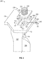
FIG. 3 illustrates an exploded view of a variable vane adjustment system, in accordance with an embodiment of the disclosure; -
FIG. 4 illustrates an exploded view of a variable vane adjustment system, in accordance with an embodiment of the disclosure; and -
FIG. 5 is a diagram of a method of assembling a variable vane adjustment system, according to an embodiment of the present disclosure. - A detailed description of one or more embodiments of the disclosed apparatus and method are presented herein by way of exemplification and not limitation with reference to the Figures.
-
FIG. 1 schematically illustrates agas turbine engine 20. Thegas turbine engine 20 is disclosed herein as a two-spool turbofan that generally incorporates afan section 22, acompressor section 24, acombustor section 26 and aturbine section 28. Alternative engines might include an augmentor section (not shown) among other systems or features. Thefan section 22 drives air along a bypass flow path B in a bypass duct, while thecompressor section 24 drives air along a core flow path C for compression and communication into thecombustor section 26 then expansion through theturbine section 28. Although depicted as a two-spool turbofan gas turbine engine in the disclosed non-limiting embodiment, it should be understood that the concepts described herein are not limited to use with two-spool turbofans as the teachings may be applied to other types of turbine engines including three-spool architectures. - The
exemplary engine 20 generally includes alow speed spool 30 and ahigh speed spool 32 mounted for rotation about an engine central longitudinal axis A relative to an enginestatic structure 36 viaseveral bearing systems 38. It should be understood thatvarious bearing systems 38 at various locations may alternatively or additionally be provided, and the location ofbearing systems 38 may be varied as appropriate to the application. - The
low speed spool 30 generally includes aninner shaft 40 that interconnects afan 42, alow pressure compressor 44 and alow pressure turbine 46. Theinner shaft 40 is connected to thefan 42 through a speed change mechanism, which in exemplarygas turbine engine 20 is illustrated as a gearedarchitecture 48 to drive thefan 42 at a lower speed than thelow speed spool 30. Thehigh speed spool 32 includes anouter shaft 50 that interconnects ahigh pressure compressor 52 andhigh pressure turbine 54. Acombustor 56 is arranged inexemplary gas turbine 20 between thehigh pressure compressor 52 and thehigh pressure turbine 54. An enginestatic structure 36 is arranged generally between thehigh pressure turbine 54 and thelow pressure turbine 46. The enginestatic structure 36 further supports bearingsystems 38 in theturbine section 28. Theinner shaft 40 and theouter shaft 50 are concentric and rotate viabearing systems 38 about the engine central longitudinal axis A which is collinear with their longitudinal axes. - The core airflow is compressed by the
low pressure compressor 44 then thehigh pressure compressor 52, mixed and burned with fuel in thecombustor 56, then expanded over thehigh pressure turbine 54 andlow pressure turbine 46. Theturbines low speed spool 30 andhigh speed spool 32 in response to the expansion. It will be appreciated that each of the positions of thefan section 22,compressor section 24,combustor section 26,turbine section 28, and fandrive gear system 48 may be varied. For example,gear system 48 may be located aft ofcombustor section 26 or even aft ofturbine section 28, andfan section 22 may be positioned forward or aft of the location ofgear system 48. - The
engine 20 in one example is a high-bypass geared aircraft engine. In a further example, theengine 20 bypass ratio is greater than about six (6), with an example embodiment being greater than about ten (10), the gearedarchitecture 48 is an epicyclic gear train, such as a planetary gear system or other gear system, with a gear reduction ratio of greater than about 2.3 and thelow pressure turbine 46 has a pressure ratio that is greater than about five. In one disclosed embodiment, theengine 20 bypass ratio is greater than about ten (10:1), the fan diameter is significantly larger than that of thelow pressure compressor 44, and thelow pressure turbine 46 has a pressure ratio that is greater than about five 5:1.Low pressure turbine 46 pressure ratio is pressure measured prior to inlet oflow pressure turbine 46 as related to the pressure at the outlet of thelow pressure turbine 46 prior to an exhaust nozzle. The gearedarchitecture 48 may be an epicycle gear train, such as a planetary gear system or other gear system, with a gear reduction ratio of greater than about 2.3:1. It should be understood, however, that the above parameters are only exemplary of one embodiment of a geared architecture engine and that the present disclosure is applicable to other gas turbine engines including direct drive turbofans. - A significant amount of thrust is provided by the bypass flow B due to the high bypass ratio. The
fan section 22 of theengine 20 is designed for a particular flight condition--typically cruise at about 0.8Mach and about 35,000 feet (10,668 meters). The flight condition of 0.8 Mach and 35,000 ft (10,668 meters), with the engine at its best fuel consumption--also known as "bucket cruise Thrust Specific Fuel Consumption ('TSFC')"--is the industry standard parameter of lbm of fuel being burned divided by lbf of thrust the engine produces at that minimum point. "Low fan pressure ratio" is the pressure ratio across the fan blade alone, without a Fan Exit Guide Vane ("FEGV") system. The low fan pressure ratio as disclosed herein according to one non-limiting embodiment is less than about 1.45. "Low corrected fan tip speed" is the actual fan tip speed in ft/sec divided by an industry standard temperature correction of [(Tram °R)/(518.7 °R)]0.5. The "Low corrected fan tip speed" as disclosed herein according to one non-limiting embodiment is less than about 1150 ft/second (350.5 m/sec). -
FIG. 2 illustrates a cross-sectional view of a portion of thecompressor section 24, which may reside in thelow pressure compressor 44 or thehigh pressure compressor 52. Further, while the embodiments disclosed herein are described in the context of thecompressor section 24, the present disclosure may be applied to theturbine section 28. Thecompressor section 24 includes acompressor rotor 100 that is rotatable about the engine central longitudinal axis A and includes one or more stages or circumferentially extending rows ofblades 102. Thecompressor section 24 further includes one or more vane stages 110 each including a circumferentially extending row ofvariable vanes 104, in an axially alternating arrangement with theblades 102. Thevariable vanes 104 andblades 102 are disposed inside acompressor case 106. One or more of the vane stages 110 are variable-pitch vane stages 110 such that eachvariable vane 104 is rotatable about avane axis 112. Theblades 102 rotate circumferentially around the engine central longitudinal axis A. Theblades 102 do not rotate around ablade axis 122. Due to the rotatable nature of thevariable vane 104 about the vane axis 112 a distance D1 measured between thevariable vane 104 and theblade 102 may vary. The distance D1 may be measured between theleading edge 101 of theblade 102 and the trailingedge 103 of thevariable vane 104. The distance D1 may also be measured between the trailingedge 105 of theblade 102 and theleading edge 107 of thevariable vane 104. - To accomplish the desired uniform rotation of the
variable vane 104 about thevane axis 112, thevariable vanes 104 are connected to a synchronization ring 114, such that circumferential movement of the synchronization ring 114 about the engine central longitudinal axis A urges movement of each of thevariable vanes 104 about their respective vane axes 112. In the embodiment ofFIG. 2 , eachvariable vane 104 includes avane stem 116 extending through avane opening 118 in thecompressor case 106. Avane platform 210 may be attached to the compressor case 106 (seeFIGs. 3 and4 ), as discussed further below. Thevane platform 210 is a removable platform that may be integral to the fixedvane 102 that is installed into thecompressor case 106. Outside of thecompressor case 106, each vane stem 116 is connected to synchronization ring 114 via a vane arm 120. Rotation of thevane stem 116 by the vane arm 120 rotates thevariable vane 104. - Referring now to
FIG. 3 with continued reference toFIGs. 1-2 .FIG. 3 illustrates a view of variablevane adjustment system 200 for avariable vane 104, according to an embodiment of the present disclosure. The variablevane adjustment system 200 includes atrunnion carrier 220, as shown inFIG. 3 . Thetrunnion carrier 220 includes abase portion 221 that is configured to fit within arecess 180 located within thevane platform 210. Thebase portion 221 and therecess 180 may have complimentary shapes, such that thebase portions 221 fits into therecess 180 like a puzzle piece. Thebase portion 221 and therecess 180 may each have a square shape. Therecess 180 may have fourside walls 182 and abottom base 184. The square shape of thebase portion 221 is smaller than the square shape of therecess 180, so that thebase portion 221 will fit within therecess 180. There is some room (i.e., play) for thebase portion 221 to move within therecess 180 in the forward direction X1 and the aft direction X2. The fit of thebase portion 221 within therecess 180 restricts motion of thebase portion 221 in a direction perpendicular to the forward direction X1 and the aft direction X2, such that, thebase portion 221 may exhibit little to no motion in the direction perpendicular to the forward direction X1 and the aft direction X2. Thetrunnion carrier 220 also includes anorifice 224 that extends through thebase portion 221 and thebushing 222. The vane stem 116 of thevariable vane 104 extends through avane opening 118 in thevane platform 210, and through theorifice 224 of thetrunnion carrier 220. - The variable
vane adjustment system 200 includes aset screw 240 that is inserted into a set screw opening 242 from anaft side 172 of thevane platform 210. The set screw opening 242 may extend from theaft side 172 of thevane platform 210 to therecess 180 within thevane platform 210. In other embodiments, the set screw opening 242 may also extend from aforward side 174 of thevane platform 210 to therecess 180 of thevane platform 210. In another embodiment, the set screw opening 242 may be a blind hole extending from anaft wall 182a or aforward wall 182b into thevane platform 210. Theset screw 240 is configured to project into therecess 180 and impact thebase portion 221 of thetrunnion carrier 220 to move thetrunnion carrier 220 and thevariable vane 104 in a forward direction X1 or an aft direction X2. Thescrew 240 projects into the recess 180 a projection distance D2 as measured away from awall 182 of therecess 180. As shown inFIG. 3 , thescrew 240 may project into therecess 180 away from anaft wall 182a of therecess 180. - Referring now to
FIG. 4 with continued reference toFIGs. 1-2 .FIG. 4 illustrates a view of variablevane adjustment system 200 for avariable vane 104, according to an embodiment of the present disclosure. The variablevane adjustment system 200 includes atrunnion carrier 220, as shown inFIG. 4 . Thetrunnion carrier 220 includes abase portion 221 that is configured to fit within arecess 180 located within thevane platform 210. Thebase portion 221 and therecess 180 may have complimentary shapes, such that thebase portions 221 fits into therecess 180 like a puzzle piece. Thebase portion 221 and therecess 180 may each have a square shape. Therecess 180 may have fourside walls 182 and abottom base 184. The square shape of thebase portion 221 is smaller than the square shape of therecess 180, so that thebase portion 221 will fit within therecess 180. There is some room (i.e., play) for thebase portion 221 to move within therecess 180 in the forward direction X1 and the aft direction X2. The fit of thebase portion 221 within therecess 180 restricts motion of thebase portion 221 in a direction perpendicular to the forward direction X1 and the aft direction X2, such that, thebase portion 221 may exhibit little to no motion in the direction perpendicular to the forward direction X1 and the aft direction X2. Thetrunnion carrier 220 also includes anorifice 224 that extends through thebase portion 221 and thebushing 222. The vane stem 116 of thevariable vane 104 extends through avane opening 118 in thevane platform 210, and through theorifice 224 of thetrunnion carrier 220. - The variable
vane adjustment system 200 includes aset screw 240 that is inserted into a set screw opening 244 from aforward side 174 of thevane platform 210. The set screw opening 244 may extend from theforward side 174 of thevane platform 210 to therecess 180 within thevane platform 210. In other embodiments, the set screw opening 244 may also extend from anaft side 172 of thevane platform 210 to therecess 180 of thevane platform 210. In another embodiment, the set screw opening 244 may be a blind hole extending from anaft wall 182a or aforward wall 182b into thevane platform 210. Theset screw 240 is configured to project into therecess 180 and impact thebase portion 221 of thetrunnion carrier 220 to move thetrunnion carrier 220 and thevariable vane 104 in a forward direction X1 or an aft direction X2. Thescrew 240 projects into the recess 180 a projection distance D2 as measured away from awall 182 of therecess 180. As shown inFIG. 4 , thescrew 240 may project into therecess 180 away from aforward wall 182b of therecess 180. - A
biasing mechanism 290 may be located at anaft wall 182a opposite theforward wall 182b of therecess 180. In an embodiment, thebiasing mechanism 290 is a spring. Thebiasing mechanism 290 is configured to counter balance the force applied by theset screw 240 on the base portion of thetrunnion carrier 220. Thebiasing mechanism 290 may be located on theaft wall 182a or within abiasing mechanism opening 192. - The
biasing mechanism opening 192 may extend from theaft side 172 of thevane platform 210 to therecess 180 within thevane platform 210. Thebiasing mechanism opening 192 may also be a blind hole originating from theaft side 182a of therecess 180 and extending into thevane platform 210 towards theaft side 172 of the vane platform. In other embodiments not shown, thebiasing mechanism opening 192 may extend from theforward side 174 of thevane platform 210 to therecess 180 within thevane platform 210. Also, in other embodiments not shown, thebiasing mechanism opening 192 may also be a blind hole originating from theforward side 182b of therecess 180 and extending into thevane platform 210 towards theforward side 174 of the vane platform. Thebiasing mechanism 290 is configured to project into therecess 180 and impact thebase portion 221 of thetrunnion carrier 220 to push/pull thetrunnion carrier 220 and thevariable vane 104 in a forward direction X1 and/or an aft direction X2. The biasing mechanism projects into the recess 180 a projection distance D3 as measured away from awall 182 of therecess 180. - Referring now to
FIG. 5 with continued reference toFIGs. 1-4 .Fig. 5 illustrates a method of assembling a variablevane adjustment system 200. Atblock 504, aset screw 240 is inserted at least partially into aset screw opening recess 180 within avane platform 210. In an embodiment, the first wall of therecess 180 is anaft wall 182a. In another embodiment, the first wall of therecess 180 is aforward wall 182b. Theset screw opening vane platform 210. In an embodiment, the set screw opening 242 may extend from the first wall of therecess 180 to anaft side 172 of thevane platform 210 if the first wall is anaft wall 182a. In an embodiment, the set screw opening 244 may extend from the first wall of therecess 180 to aforward side 174 of thevane platform 210 if the first wall is aforward wall 182b. Theset screw 240 is configured to longitudinally traverse theset screw opening set screw 240 is rotated. - At
block 506, atrunnion carrier 220 is inserted at least partially into therecess 180 of thevane platform 210. Thetrunnion carrier 220 having abase portion 221 located at least partially within therecess 180, abushing 222 attached to thebase portion 221, and anorifice 224 that extends through thebase portion 221 and thebushing 222. Thebase portion 221 is configured to fit at least partially within therecess 180 of thevane platform 210. - At
block 508, theorifice 224 of thetrunnion carrier 220 is aligned with avane opening 118 located within therecess 180 of thevane platform 210. Atblock 510, avane stem 116 of avariable vane 104 is inserted through thevane opening 118 of thevane platform 210 and theorifice 224 of thetrunnion carrier 220. - At
block 512, theset screw 240 is rotated at least partially within theset screw opening base portion 221 of thetrunnion carrier 220. Atblock 514, the position of thetrunnion carrier 220 and thevariable vane 104 is adjusted using theset screw 240 by rotating theset screw 240 to at least partially project into therecess 180 and impact thebase portion 221 of thetrunnion carrier 220 to move thetrunnion carrier 220 and thevariable vane 104 in a forward direction X1 or aft direction X2. - The
method 500 may further comprise: operably connecting abiasing mechanism 290 to thevane platform 210. Thebiasing mechanism 290 is located at a second wall of the recess opposite the first wall and may at least partially project into therecess 180. The second wall of the recess is opposite the location of theset screw opening aft wall 182a or theforward wall 182b. Thebiasing mechanism 290 may be located at least partially within abiasing mechanism opening 192 originating at the second wall and extending into thevane platform 210. - While the above description has described the flow process of
FIG. 5 in a particular order, it should be appreciated that unless otherwise specifically required in the attached claims that the ordering of the steps may be varied. - Technical effects of embodiments of the present disclosure include adjusting a location of a variable vane using a set screw.
- The term "about" is intended to include the degree of error associated with measurement of the particular quantity based upon the equipment available at the time of filing the application.
- The terminology used herein is for the purpose of describing particular embodiments only and is not intended to be limiting of the present disclosure. As used herein, the singular forms "a", "an" and "the" are intended to include the plural forms as well, unless the context clearly indicates otherwise. It will be further understood that the terms "comprises" and/or "comprising," when used in this specification, specify the presence of stated features, integers, steps, operations, elements, and/or components, but do not preclude the presence or addition of one or more other features, integers, steps, operations, element components, and/or groups thereof.
- While the present disclosure has been described with reference to an exemplary embodiment or embodiments, it will be understood by those skilled in the art that various changes may be made and equivalents may be substituted for elements thereof without departing from the scope of the present disclosure. In addition, many modifications may be made to adapt a particular situation or material to the teachings of the present disclosure without departing from the essential scope thereof. Therefore, it is intended that the present disclosure not be limited to the particular embodiment disclosed as the best mode contemplated for carrying out this present disclosure, but that the present disclosure will include all embodiments falling within the scope of the claims.
Claims (15)
- A variable vane adjustment system (200) for a gas turbine engine (20), comprising:a vane platform (210) having a recess (180), a vane opening (118) within the recess, and a set screw opening (242; 244) originating at a first wall (182a, 182b) of the recess and extending into the vane platform;a trunnion carrier (220) having a base portion (221) located at least partially within the recess, a bushing (222) attached to the base portion, and an orifice (224) that extends through the base portion and the bushing, wherein the orifice is aligned with the vane opening;a variable vane (104) having a vane stem (116), the vane stem extending through the vane opening of the vane platform and the orifice of the trunnion carrier; anda set screw (240) located at least partially within the set screw opening, the set screw being configured to longitudinally traverse the set screw opening as the set screw is rotated, wherein the set screw is configured to project into the recess and impact the base portion of the trunnion carrier to move the trunnion carrier and the variable vane in a forward direction (XI) or aft direction (X2).
- The variable vane adjustment system of claim 1, wherein the first wall of the recess is an aft wall (182a).
- The variable vane adjustment system of claim 1, wherein the first wall of the recess is a forward wall (182b).
- The variable vane adjustment system of claim 2, wherein the set screw opening (242) extends from the first wall (182a) of the recess to an aft side (172) of the vane platform (210).
- The variable vane adjustment system of claim 3, wherein the set screw opening (244) extends from the first wall (182b) of the recess to a forward side (174) of the vane platform (210).
- The variable vane adjustment system of any preceding claim, further comprising:
a biasing mechanism (290) located at a second wall of the recess opposite the first wall, the biasing mechanism at least partially projecting into the recess (180) optionally wherein the second wall of the recess is an aft wall (182a), or wherein the second wall of the recess is a forward wall (182b). - The variable vane adjustment system of claim 6, wherein the biasing mechanism (290) is located at least partially within a biasing mechanism opening (192) originating at the second wall (182a) and extending into the vane platform (210).
- The variable vane adjustment system of claim 6 or 7, wherein the biasing mechanism (290) is a spring.
- The variable vane adjustment system of claim 6, 7 or 8, wherein the biasing mechanism (290) is attached to the second wall (182a).
- A method of assembling a variable vane adjustment system (200) for a gas turbine engine (20), comprising:inserting (504) a set screw (240) at least partially into a set screw opening (242; 244) originating at a first wall (182a; 182b) of a recess (180) within a vane platform (210), the set screw opening extending from the first wall into the vane platform, wherein the set screw is configured to longitudinally traverse the set screw opening as the set screw is rotated;inserting (506) a trunnion carrier (220) at least partially into the recess of the vane platform (210), the trunnion carrier having a base portion (221) located at least partially within the recess (180), a bushing (222) attached to the base portion, and an orifice (224) that extends through the base portion and the bushing; wherein the base portion is configured to fit at least partially within the recess of the vane platform;aligning (508) the orifice (224) of the trunnion carrier (220) with a vane opening (118) located within the recess (180) of the vane platform (210);inserting (510) a vane stem (116) of a variable vane (104) through the vane opening (118) of the vane platform (210) and the orifice (224) of the trunnion carrier (220);rotating (512) the set screw (240) at least partially within the set screw opening (242; 244) to move the set screw towards or away from the base portion (221) of the trunnion carrier (220); andadjusting (514) the position of the trunnion carrier (220) and the variable vane (104) using the set screw (240) by rotating the set screw (240) to at least partially project into the recess (180) and impact the base portion (221) of the trunnion carrier (220) to move the trunnion carrier and the variable vane (104) in a forward direction or aft direction.
- The method of claim 10, wherein the first wall of the recess (180) is an aft wall (182a), and optionally wherein the set screw opening (242) extends from the first wall (182a) of the recess to an aft side (172) of the vane platform (210).
- The method of claim 10, wherein the first wall of the recess (180) is a forward wall (182b), and optionally wherein the set screw opening (244) extends from the first wall (182b) of the recess to a forward side (174) of the vane platform (210).
- The method of any of claims 10 to 12, further comprising:
operably connecting a biasing mechanism (290) to the vane platform (210), wherein the biasing mechanism is located at a second wall of the recess (180) opposite the first wall and at least partially projects into the recess. - The method of claim 13, wherein the second wall of the recess (180) is an aft wall (182a), or wherein the second wall of the recess is a forward wall (182b).
- The method of claim 13 or 14, wherein the biasing mechanism (290) is located at least partially within a biasing mechanism opening (192) originating at the second wall and extending into the vane platform (210).
Applications Claiming Priority (1)
| Application Number | Priority Date | Filing Date | Title |
|---|---|---|---|
| US16/130,042 US10774674B2 (en) | 2018-09-13 | 2018-09-13 | Set screw gap control between fixed and variable vanes |
Publications (2)
| Publication Number | Publication Date |
|---|---|
| EP3623584A1 true EP3623584A1 (en) | 2020-03-18 |
| EP3623584B1 EP3623584B1 (en) | 2021-05-19 |
Family
ID=67262236
Family Applications (1)
| Application Number | Title | Priority Date | Filing Date |
|---|---|---|---|
| EP19186163.2A Active EP3623584B1 (en) | 2018-09-13 | 2019-07-12 | Set screw gap control between fixed and variable vanes |
Country Status (2)
| Country | Link |
|---|---|
| US (1) | US10774674B2 (en) |
| EP (1) | EP3623584B1 (en) |
Families Citing this family (3)
| Publication number | Priority date | Publication date | Assignee | Title |
|---|---|---|---|---|
| BE1029274B1 (en) * | 2021-04-06 | 2022-11-04 | Safran Aero Boosters | Stator vane group |
| FR3124825B1 (en) | 2021-06-30 | 2023-05-26 | Safran Aircraft Engines | PROPELLER FOR AN AIRCRAFT TURBOMACHINE WITH A VARIABLE-PITCHED BLADE AND A GEARED COUNTERWEIGHT DEVICE |
| US11655778B2 (en) * | 2021-08-06 | 2023-05-23 | Raytheon Technologies Corporation | Morphing structures for fan inlet variable vanes |
Citations (3)
| Publication number | Priority date | Publication date | Assignee | Title |
|---|---|---|---|---|
| US4363600A (en) * | 1981-04-06 | 1982-12-14 | General Motors Corporation | Variable vane mounting |
| EP1340894A2 (en) * | 2002-02-28 | 2003-09-03 | General Electric Company | Variable inlet guide vanes for varying gas turbine engine inlet air flow |
| US20080145206A1 (en) * | 2006-12-19 | 2008-06-19 | Rolls-Royce North American Technologies, Inc. | Passive guide vane control |
Family Cites Families (5)
| Publication number | Priority date | Publication date | Assignee | Title |
|---|---|---|---|---|
| JP2010196550A (en) * | 2009-02-24 | 2010-09-09 | Mitsubishi Heavy Ind Ltd | Structure for mounting between rotation shaft and lever, method for mounting between rotation shaft and lever, and fluid machine |
| US9303524B2 (en) | 2012-10-25 | 2016-04-05 | Solar Turbines Incorporated | Variable area turbine nozzle with a position selector |
| US10215056B2 (en) * | 2015-06-30 | 2019-02-26 | Rolls-Royce Corporation | Turbine shroud with movable attachment features |
| US10352186B2 (en) | 2016-01-22 | 2019-07-16 | United Technologies Corporation | Variable vane stabilizer |
| US10634000B2 (en) * | 2017-06-23 | 2020-04-28 | Rolls-Royce North American Technologies Inc. | Method and configuration for improved variable vane positioning |
-
2018
- 2018-09-13 US US16/130,042 patent/US10774674B2/en active Active
-
2019
- 2019-07-12 EP EP19186163.2A patent/EP3623584B1/en active Active
Patent Citations (3)
| Publication number | Priority date | Publication date | Assignee | Title |
|---|---|---|---|---|
| US4363600A (en) * | 1981-04-06 | 1982-12-14 | General Motors Corporation | Variable vane mounting |
| EP1340894A2 (en) * | 2002-02-28 | 2003-09-03 | General Electric Company | Variable inlet guide vanes for varying gas turbine engine inlet air flow |
| US20080145206A1 (en) * | 2006-12-19 | 2008-06-19 | Rolls-Royce North American Technologies, Inc. | Passive guide vane control |
Also Published As
| Publication number | Publication date |
|---|---|
| US20200088063A1 (en) | 2020-03-19 |
| US10774674B2 (en) | 2020-09-15 |
| EP3623584B1 (en) | 2021-05-19 |
Similar Documents
| Publication | Publication Date | Title |
|---|---|---|
| US10060285B2 (en) | Variable vane control system | |
| US20200332673A1 (en) | Adaptive case for a gas turbine engine | |
| EP3536912A1 (en) | Profiled bellcrank vane actuation system | |
| US10358934B2 (en) | Method and apparatus for adjusting variable vanes | |
| EP3760838B1 (en) | Gas turbine variable vane system and method | |
| EP3249199B1 (en) | Gas turbine engine inlet temperature sensor configuration and corresponding method | |
| US11199102B2 (en) | Hydrostatic seal with increased design space | |
| EP3623584B1 (en) | Set screw gap control between fixed and variable vanes | |
| EP3633153A1 (en) | Bell crank and bar assembly | |
| EP3453830B1 (en) | Vane for variable area turbine | |
| EP3770381B1 (en) | Self retained linkage and system including the self retained linkage for a gas turbine engine | |
| EP3470656B1 (en) | Modulated combustor bypass | |
| EP3431716B1 (en) | Variable-pitch vane assembly and corresponding assembly method | |
| EP3508790B1 (en) | Gas turbine engine with modulated combustor bypass and combustor bypass valve | |
| US12158078B2 (en) | Compressor case with a cooling cavity | |
| EP3385508A1 (en) | Bellcrank assembly for gas turbine engine and corrsponding method | |
| EP4372208A1 (en) | Seal for gas turbine engine | |
| EP3564491B1 (en) | Variable vane actuation system with nested direct vane angle measurement shaft | |
| EP3460226B1 (en) | Moveable exhaust plug liner |
Legal Events
| Date | Code | Title | Description |
|---|---|---|---|
| PUAI | Public reference made under article 153(3) epc to a published international application that has entered the european phase |
Free format text: ORIGINAL CODE: 0009012 |
|
| STAA | Information on the status of an ep patent application or granted ep patent |
Free format text: STATUS: THE APPLICATION HAS BEEN PUBLISHED |
|
| AK | Designated contracting states |
Kind code of ref document: A1 Designated state(s): AL AT BE BG CH CY CZ DE DK EE ES FI FR GB GR HR HU IE IS IT LI LT LU LV MC MK MT NL NO PL PT RO RS SE SI SK SM TR |
|
| AX | Request for extension of the european patent |
Extension state: BA ME |
|
| STAA | Information on the status of an ep patent application or granted ep patent |
Free format text: STATUS: REQUEST FOR EXAMINATION WAS MADE |
|
| 17P | Request for examination filed |
Effective date: 20200918 |
|
| RBV | Designated contracting states (corrected) |
Designated state(s): AL AT BE BG CH CY CZ DE DK EE ES FI FR GB GR HR HU IE IS IT LI LT LU LV MC MK MT NL NO PL PT RO RS SE SI SK SM TR |
|
| GRAP | Despatch of communication of intention to grant a patent |
Free format text: ORIGINAL CODE: EPIDOSNIGR1 |
|
| STAA | Information on the status of an ep patent application or granted ep patent |
Free format text: STATUS: GRANT OF PATENT IS INTENDED |
|
| RIC1 | Information provided on ipc code assigned before grant |
Ipc: F01D 5/14 20060101ALI20201103BHEP Ipc: F01D 17/16 20060101AFI20201103BHEP |
|
| INTG | Intention to grant announced |
Effective date: 20201130 |
|
| RAP1 | Party data changed (applicant data changed or rights of an application transferred) |
Owner name: RAYTHEON TECHNOLOGIES CORPORATION |
|
| GRAS | Grant fee paid |
Free format text: ORIGINAL CODE: EPIDOSNIGR3 |
|
| GRAA | (expected) grant |
Free format text: ORIGINAL CODE: 0009210 |
|
| STAA | Information on the status of an ep patent application or granted ep patent |
Free format text: STATUS: THE PATENT HAS BEEN GRANTED |
|
| AK | Designated contracting states |
Kind code of ref document: B1 Designated state(s): AL AT BE BG CH CY CZ DE DK EE ES FI FR GB GR HR HU IE IS IT LI LT LU LV MC MK MT NL NO PL PT RO RS SE SI SK SM TR |
|
| REG | Reference to a national code |
Ref country code: GB Ref legal event code: FG4D |
|
| REG | Reference to a national code |
Ref country code: CH Ref legal event code: EP |
|
| REG | Reference to a national code |
Ref country code: DE Ref legal event code: R096 Ref document number: 602019004669 Country of ref document: DE |
|
| REG | Reference to a national code |
Ref country code: AT Ref legal event code: REF Ref document number: 1394151 Country of ref document: AT Kind code of ref document: T Effective date: 20210615 |
|
| REG | Reference to a national code |
Ref country code: IE Ref legal event code: FG4D |
|
| REG | Reference to a national code |
Ref country code: LT Ref legal event code: MG9D |
|
| REG | Reference to a national code |
Ref country code: AT Ref legal event code: MK05 Ref document number: 1394151 Country of ref document: AT Kind code of ref document: T Effective date: 20210519 |
|
| REG | Reference to a national code |
Ref country code: NL Ref legal event code: MP Effective date: 20210519 |
|
| PG25 | Lapsed in a contracting state [announced via postgrant information from national office to epo] |
Ref country code: FI Free format text: LAPSE BECAUSE OF FAILURE TO SUBMIT A TRANSLATION OF THE DESCRIPTION OR TO PAY THE FEE WITHIN THE PRESCRIBED TIME-LIMIT Effective date: 20210519 Ref country code: HR Free format text: LAPSE BECAUSE OF FAILURE TO SUBMIT A TRANSLATION OF THE DESCRIPTION OR TO PAY THE FEE WITHIN THE PRESCRIBED TIME-LIMIT Effective date: 20210519 Ref country code: LT Free format text: LAPSE BECAUSE OF FAILURE TO SUBMIT A TRANSLATION OF THE DESCRIPTION OR TO PAY THE FEE WITHIN THE PRESCRIBED TIME-LIMIT Effective date: 20210519 Ref country code: AT Free format text: LAPSE BECAUSE OF FAILURE TO SUBMIT A TRANSLATION OF THE DESCRIPTION OR TO PAY THE FEE WITHIN THE PRESCRIBED TIME-LIMIT Effective date: 20210519 Ref country code: BG Free format text: LAPSE BECAUSE OF FAILURE TO SUBMIT A TRANSLATION OF THE DESCRIPTION OR TO PAY THE FEE WITHIN THE PRESCRIBED TIME-LIMIT Effective date: 20210819 |
|
| PG25 | Lapsed in a contracting state [announced via postgrant information from national office to epo] |
Ref country code: GR Free format text: LAPSE BECAUSE OF FAILURE TO SUBMIT A TRANSLATION OF THE DESCRIPTION OR TO PAY THE FEE WITHIN THE PRESCRIBED TIME-LIMIT Effective date: 20210820 Ref country code: IS Free format text: LAPSE BECAUSE OF FAILURE TO SUBMIT A TRANSLATION OF THE DESCRIPTION OR TO PAY THE FEE WITHIN THE PRESCRIBED TIME-LIMIT Effective date: 20210919 Ref country code: LV Free format text: LAPSE BECAUSE OF FAILURE TO SUBMIT A TRANSLATION OF THE DESCRIPTION OR TO PAY THE FEE WITHIN THE PRESCRIBED TIME-LIMIT Effective date: 20210519 Ref country code: NO Free format text: LAPSE BECAUSE OF FAILURE TO SUBMIT A TRANSLATION OF THE DESCRIPTION OR TO PAY THE FEE WITHIN THE PRESCRIBED TIME-LIMIT Effective date: 20210819 Ref country code: PL Free format text: LAPSE BECAUSE OF FAILURE TO SUBMIT A TRANSLATION OF THE DESCRIPTION OR TO PAY THE FEE WITHIN THE PRESCRIBED TIME-LIMIT Effective date: 20210519 Ref country code: RS Free format text: LAPSE BECAUSE OF FAILURE TO SUBMIT A TRANSLATION OF THE DESCRIPTION OR TO PAY THE FEE WITHIN THE PRESCRIBED TIME-LIMIT Effective date: 20210519 Ref country code: SE Free format text: LAPSE BECAUSE OF FAILURE TO SUBMIT A TRANSLATION OF THE DESCRIPTION OR TO PAY THE FEE WITHIN THE PRESCRIBED TIME-LIMIT Effective date: 20210519 Ref country code: PT Free format text: LAPSE BECAUSE OF FAILURE TO SUBMIT A TRANSLATION OF THE DESCRIPTION OR TO PAY THE FEE WITHIN THE PRESCRIBED TIME-LIMIT Effective date: 20210920 |
|
| PG25 | Lapsed in a contracting state [announced via postgrant information from national office to epo] |
Ref country code: NL Free format text: LAPSE BECAUSE OF FAILURE TO SUBMIT A TRANSLATION OF THE DESCRIPTION OR TO PAY THE FEE WITHIN THE PRESCRIBED TIME-LIMIT Effective date: 20210519 |
|
| PG25 | Lapsed in a contracting state [announced via postgrant information from national office to epo] |
Ref country code: CZ Free format text: LAPSE BECAUSE OF FAILURE TO SUBMIT A TRANSLATION OF THE DESCRIPTION OR TO PAY THE FEE WITHIN THE PRESCRIBED TIME-LIMIT Effective date: 20210519 Ref country code: DK Free format text: LAPSE BECAUSE OF FAILURE TO SUBMIT A TRANSLATION OF THE DESCRIPTION OR TO PAY THE FEE WITHIN THE PRESCRIBED TIME-LIMIT Effective date: 20210519 Ref country code: RO Free format text: LAPSE BECAUSE OF FAILURE TO SUBMIT A TRANSLATION OF THE DESCRIPTION OR TO PAY THE FEE WITHIN THE PRESCRIBED TIME-LIMIT Effective date: 20210519 Ref country code: SM Free format text: LAPSE BECAUSE OF FAILURE TO SUBMIT A TRANSLATION OF THE DESCRIPTION OR TO PAY THE FEE WITHIN THE PRESCRIBED TIME-LIMIT Effective date: 20210519 Ref country code: SK Free format text: LAPSE BECAUSE OF FAILURE TO SUBMIT A TRANSLATION OF THE DESCRIPTION OR TO PAY THE FEE WITHIN THE PRESCRIBED TIME-LIMIT Effective date: 20210519 Ref country code: EE Free format text: LAPSE BECAUSE OF FAILURE TO SUBMIT A TRANSLATION OF THE DESCRIPTION OR TO PAY THE FEE WITHIN THE PRESCRIBED TIME-LIMIT Effective date: 20210519 Ref country code: ES Free format text: LAPSE BECAUSE OF FAILURE TO SUBMIT A TRANSLATION OF THE DESCRIPTION OR TO PAY THE FEE WITHIN THE PRESCRIBED TIME-LIMIT Effective date: 20210519 |
|
| REG | Reference to a national code |
Ref country code: DE Ref legal event code: R097 Ref document number: 602019004669 Country of ref document: DE |
|
| PLBE | No opposition filed within time limit |
Free format text: ORIGINAL CODE: 0009261 |
|
| STAA | Information on the status of an ep patent application or granted ep patent |
Free format text: STATUS: NO OPPOSITION FILED WITHIN TIME LIMIT |
|
| PG25 | Lapsed in a contracting state [announced via postgrant information from national office to epo] |
Ref country code: MC Free format text: LAPSE BECAUSE OF FAILURE TO SUBMIT A TRANSLATION OF THE DESCRIPTION OR TO PAY THE FEE WITHIN THE PRESCRIBED TIME-LIMIT Effective date: 20210519 |
|
| REG | Reference to a national code |
Ref country code: BE Ref legal event code: MM Effective date: 20210731 |
|
| 26N | No opposition filed |
Effective date: 20220222 |
|
| PG25 | Lapsed in a contracting state [announced via postgrant information from national office to epo] |
Ref country code: IS Free format text: LAPSE BECAUSE OF FAILURE TO SUBMIT A TRANSLATION OF THE DESCRIPTION OR TO PAY THE FEE WITHIN THE PRESCRIBED TIME-LIMIT Effective date: 20210919 Ref country code: LU Free format text: LAPSE BECAUSE OF NON-PAYMENT OF DUE FEES Effective date: 20210712 Ref country code: AL Free format text: LAPSE BECAUSE OF FAILURE TO SUBMIT A TRANSLATION OF THE DESCRIPTION OR TO PAY THE FEE WITHIN THE PRESCRIBED TIME-LIMIT Effective date: 20210519 |
|
| PG25 | Lapsed in a contracting state [announced via postgrant information from national office to epo] |
Ref country code: IT Free format text: LAPSE BECAUSE OF FAILURE TO SUBMIT A TRANSLATION OF THE DESCRIPTION OR TO PAY THE FEE WITHIN THE PRESCRIBED TIME-LIMIT Effective date: 20210519 Ref country code: IE Free format text: LAPSE BECAUSE OF NON-PAYMENT OF DUE FEES Effective date: 20210712 Ref country code: BE Free format text: LAPSE BECAUSE OF NON-PAYMENT OF DUE FEES Effective date: 20210731 |
|
| REG | Reference to a national code |
Ref country code: CH Ref legal event code: PL |
|
| PG25 | Lapsed in a contracting state [announced via postgrant information from national office to epo] |
Ref country code: LI Free format text: LAPSE BECAUSE OF NON-PAYMENT OF DUE FEES Effective date: 20220731 Ref country code: CH Free format text: LAPSE BECAUSE OF NON-PAYMENT OF DUE FEES Effective date: 20220731 |
|
| P01 | Opt-out of the competence of the unified patent court (upc) registered |
Effective date: 20230521 |
|
| PG25 | Lapsed in a contracting state [announced via postgrant information from national office to epo] |
Ref country code: CY Free format text: LAPSE BECAUSE OF FAILURE TO SUBMIT A TRANSLATION OF THE DESCRIPTION OR TO PAY THE FEE WITHIN THE PRESCRIBED TIME-LIMIT Effective date: 20210519 |
|
| PG25 | Lapsed in a contracting state [announced via postgrant information from national office to epo] |
Ref country code: HU Free format text: LAPSE BECAUSE OF FAILURE TO SUBMIT A TRANSLATION OF THE DESCRIPTION OR TO PAY THE FEE WITHIN THE PRESCRIBED TIME-LIMIT; INVALID AB INITIO Effective date: 20190712 |
|
| PG25 | Lapsed in a contracting state [announced via postgrant information from national office to epo] |
Ref country code: MK Free format text: LAPSE BECAUSE OF FAILURE TO SUBMIT A TRANSLATION OF THE DESCRIPTION OR TO PAY THE FEE WITHIN THE PRESCRIBED TIME-LIMIT Effective date: 20210519 |
|
| PG25 | Lapsed in a contracting state [announced via postgrant information from national office to epo] |
Ref country code: MT Free format text: LAPSE BECAUSE OF FAILURE TO SUBMIT A TRANSLATION OF THE DESCRIPTION OR TO PAY THE FEE WITHIN THE PRESCRIBED TIME-LIMIT Effective date: 20210519 |
|
| PGFP | Annual fee paid to national office [announced via postgrant information from national office to epo] |
Ref country code: GB Payment date: 20250619 Year of fee payment: 7 |
|
| PGFP | Annual fee paid to national office [announced via postgrant information from national office to epo] |
Ref country code: FR Payment date: 20250620 Year of fee payment: 7 |
|
| REG | Reference to a national code |
Ref country code: DE Ref legal event code: R081 Ref document number: 602019004669 Country of ref document: DE Owner name: RTX CORPORATION (N.D.GES.D. STAATES DELAWARE),, US Free format text: FORMER OWNER: RAYTHEON TECHNOLOGIES CORPORATION, FARMINGTON, CT, US |
|
| PGFP | Annual fee paid to national office [announced via postgrant information from national office to epo] |
Ref country code: DE Payment date: 20250620 Year of fee payment: 7 |
|
| PG25 | Lapsed in a contracting state [announced via postgrant information from national office to epo] |
Ref country code: TR Free format text: LAPSE BECAUSE OF FAILURE TO SUBMIT A TRANSLATION OF THE DESCRIPTION OR TO PAY THE FEE WITHIN THE PRESCRIBED TIME-LIMIT Effective date: 20210519 |