EP3623526A1 - Sealing arrangement and suction roll of a fibre web machine, equipped with the sealing arrangement - Google Patents
Sealing arrangement and suction roll of a fibre web machine, equipped with the sealing arrangement Download PDFInfo
- Publication number
- EP3623526A1 EP3623526A1 EP19196106.9A EP19196106A EP3623526A1 EP 3623526 A1 EP3623526 A1 EP 3623526A1 EP 19196106 A EP19196106 A EP 19196106A EP 3623526 A1 EP3623526 A1 EP 3623526A1
- Authority
- EP
- European Patent Office
- Prior art keywords
- seal
- sealing arrangement
- sensor
- arrangement according
- suction roll
- Prior art date
- Legal status (The legal status is an assumption and is not a legal conclusion. Google has not performed a legal analysis and makes no representation as to the accuracy of the status listed.)
- Granted
Links
Images


Classifications
-
- D—TEXTILES; PAPER
- D21—PAPER-MAKING; PRODUCTION OF CELLULOSE
- D21F—PAPER-MAKING MACHINES; METHODS OF PRODUCING PAPER THEREON
- D21F3/00—Press section of machines for making continuous webs of paper
- D21F3/02—Wet presses
- D21F3/10—Suction rolls, e.g. couch rolls
-
- F—MECHANICAL ENGINEERING; LIGHTING; HEATING; WEAPONS; BLASTING
- F16—ENGINEERING ELEMENTS AND UNITS; GENERAL MEASURES FOR PRODUCING AND MAINTAINING EFFECTIVE FUNCTIONING OF MACHINES OR INSTALLATIONS; THERMAL INSULATION IN GENERAL
- F16J—PISTONS; CYLINDERS; SEALINGS
- F16J15/00—Sealings
- F16J15/16—Sealings between relatively-moving surfaces
Definitions
- the invention relates to a sealing arrangement, which includes a seal holder and a seal adapted in the seal holder as well as indicator means adapted to define the wear margin of the seal. Moreover, the invention relates to a suction roll of a fibre web machine, equipped with the sealing arrangement.
- EP patent number 1141481 presents a sealing arrangement, the wear of which can be monitored. To monitor the wear, the sealing arrangement includes indicator means.
- One application of the sealing arrangement presented is a suction roll of a fibre web machine, where the suction roll has one or more sealing arrangements.
- the suction roll has a perforated shell, inside which is a suction box.
- the sealing arrangement includes a seal holder and a seal adapted in the seal holder.
- the seal holder is supported to the suction box so that the seal extends to the inner surface of the shell.
- the sealing arrangement usually also includes loading devices to load the seal.
- Some sealing arrangements also include locking means for setting the seal slightly out of contact with the shell.
- the sealing arrangements delimit the zone where the negative pressure effect of the suction box extends to the surface of the shell via the holes in the shell.
- the structure of known indicator means is complex, but the indication is still inaccurate. In this case, information on the wear margin of the seal is uncertain, which may lead to the premature replacement of the seal or to the seal wearing out.
- indicator means are sensitive to failures, and they are only applicable to certain types of sealing arrangements.
- the object of the present invention is to accomplish a novel kind of sealing arrangement, where the wear margin of the seal can be detected in a simpler manner than before but more accurately than earlier.
- the features of the sealing arrangement according to the invention will be more fully understood from the enclosed claim 1.
- the object of the present invention is to accomplish a novel kind of a suction roll of a fibre web machine, equipped with the sealing arrangement, where the wear of the seals is known at all times.
- the indicator means are of a new kind, and they have been arranged in a novel and surprising manner. Durable and simple components are used to achieve accurate indication, in which case it is easy to determine the presumable lifetime of a seal. In this case, the replacement of the seal can be planned in advance, whereby premature replacement and on the other hand wearing out can be avoided. At the same time, useful information on the functioning of the suction roll is also obtained.
- Figure 1 shows an example position of a fibre web machine, where the suction roll 10 is in a nip contact with a press roll 11.
- Water is removed from the fibre web in the nip, and the water moves to the bores on the shell of the suction roll, more generally expressed to the open surface of the suction roll.
- the transfer of water is intensified by means of negative pressure effect, which is created by means of a suction box 12 adapted inside the suction roll.
- the negative pressure is created into the suction box by some suitable device, which is usually located outside the suction box.
- By using one or more sealing arrangements it is possible to arrange a zone 13 in the nip area or also before the nip, which zone 13 has a negative pressure effect. After the zone 13, water is removed from the open surface of the suction roll usually by gravity.
- the suction roll can also be used for web control, such as for guiding the fibre web to follow a certain fabric.
- FIG 2 shows a suction roll 10 of a fibre web machine, equipped with the sealing arrangement.
- the suction roll 10 includes a perforated shell 14 supported in a rotating manner as well as a suction box 12 adapted inside the suction roll 10.
- Figure 2 only shows some of the holes 15 on the shell 14.
- the suction box 12 has at least one sealing arrangement 16 in order to delimit the negative pressure effect.
- Two sealing arrangements are typically used, and the above-mentioned zone 13 is formed between these. By using several sealing arrangements, it is possible to delimit several zones.
- Each sealing arrangement includes a seal holder 17 and a seal 18 adapted in the seal holder 17 and extending to the shell 14.
- the seal holder 17 is supported to the suction box 12.
- Both the seal holder and the seal extend essentially over the length of the entire suction box. Separate end seals are used at the ends of the suction box, where the sealing arrangement according to the invention can also be applied (not presented) .
- the sealing arrangement also includes indicator means 19 adapted to define the wear margin of the seal 18.
- the indicator means provide information on the wear margin, and it is hence possible to continuously define the remaining lifetime of the seal. A sudden change in the wear margin can also be used for detecting potential disturbance situations. Water is usually showered to the inner surface of the shell to lubricate the seal. Water reduces friction and hence slows down the wear of the seal.
- a lubrication shower pipe 20 is shown in Figure 2 . Moreover, the lubrication water can also be led along the seal or through the seal.
- the indicator means 19 include indicator material 21 and a sensor 22 adapted to detect the indicator material 21, where one of those is arranged in connection with the seal 18 and the other of those is arranged in connection with the seal holder 17 ( Figures 3a and 3b ).
- the indicator material and the sensor make up a functional pair, the features and joint functioning of which have been defined and are hence known.
- the functioning of the indicator means remains unchanged irrespective of the features of the sealing arrangement and in general irrespective of the features of the suction roll.
- the position of the seal with respect to the seal holder is known precisely. When the seal wears, the position of the seal changes, and this can subsequently be used for defining the wear margin of the seal.
- the senor is connected to suitable power supply and signal processing means 23 and advantageously linked to the machine control system 24 of the fibre web machine ( Figure 2 ).
- Wireless energy transmission and signal transmission techniques are advantageously used. Wiring can also be used.
- energy can be generated from the rotation of the suction roll, and even a battery will have a lifetime as long as the servicing interval of the suction roll, even more than one servicing interval.
- the machine control system 24 can have a connection to a cloud service 25, for example for arranging remote maintenance.
- the indicator means provide continuous information on the state of the sealing arrangement and especially on the state of the seal without stopping or opening the suction roll.
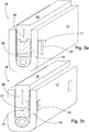
- Figures 3a and 3b show in more detail the sealing arrangement according to the invention, where the sealing arrangement includes a seal holder 17 and a seal 18 adapted in the seal holder 17.
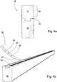
- the sealing arrangement also includes indicator means 19 adapted to define the wear margin 26 of the seal 18 ( Figure 4a ).
- the indicator means 19 include indicator material 21 and a sensor 22 adapted to detect the indicator material 21, where one of those is arranged in connection with the seal 18 and the other of those is arranged in connection with the seal holder 17. It is easy to adapt the indicator material as part of the sealing arrangement.
- the sensor detects the indicator material accurately despite surrounding structures. In other words, there is no need for an unobstructed visual contact or physical contact between the indicator means and the indicator material. Indication is therefore accurate, and the wear margin present at any given moment can be defined accurately.
- the indicator material 21 is advantageously arranged in the seal holder 17, while the sensor 22 is in the seal 18 ( Figure 3a ). Firstly, the indicator material is easy to fasten to the seal holder. Secondly, when the sensor is in the seal, it is possible to obtain also other useful information on the seal. Generally speaking, the sensor and the indicator material are adapted so close to each other that the sensor certainly detects the indicator material, and the mutual movement of the sensor and the indicator material can be converted accurately to indicate the wear margin of the seal.
- the senor 22 is arranged at both ends of the seal 18 and at the middle of the seal 18. In this case, three sensors are used, each with its own indicator material. Several sensors give more accurate information on the wear margin at the various points of the seal than a single sensor. At the same time, it can be ensured that the seal moves evenly in the seal holder. Accuracy can be increased further by increasing the number of sensors and indicator material.
- the indicator material is inside the seal 18, while the sensor 22 is in the seal holder 17. The next sensor 22 placed in a different place is indicated by a broken line.
- One advantageous indicator material 21 is a permanent magnet 27.
- the properties of a permanent magnet are stable, and a permanent magnet works without external energy. Moreover, a permanent magnet can be detected accurately even in moist conditions.
- the permanent magnet 27 is advantageously a round piece, which produces the most even magnetic field to all directions. Round permanent magnets can also be located in a row in the direction of movement of the seal. The positioning of permanent magnets is most convenient by placing them in a band or a strip to be fastened to the seal holder. In this case, the distances between permanent magnets are positioned from the outset. Positioning in the direction of movement of the seal can also be done with a wide strip or band.
- the indicator material can also be an elongated piece, which is adapted in the longitudinal direction in accordance with the direction of movement 28 of the seal 18.
- a magnetic field of a certain shape is created in the seal holder, with the main direction of the magnetic field being in the direction of movement of the seal.
- the sensor detects most accurately a change in the position in accordance with the direction of movement, which improves the accuracy of defining the wear margin.
- the indicator material and especially the permanent magnet can be detected with various types of sensors.
- an eddy current sensor is suitable for use in hot and moist conditions, and the detection length of an eddy current sensor is long.
- each sensor is advantageously composed of several HALL sensors bridged to each other.
- the movement of the seal can be determined computationally from the observations made by the different HALL sensors.
- the movement of the seal can also be determined in the machine direction and axial direction.
- the thermal expansion of the seal can be detected and therefore compensated for in the determination.
- Bridged HALL sensors can achieve an accuracy of decimals of millimetres. In practice, the wear margin of the seal is a few dozen millimetres.
- the sensor of Figure 3b has four bridged HALL sensors.
- the permanent magnet and the HALL sensor are simple and small components, which are easy to place in the sealing arrangement.
- the sealing arrangement is being manufactured, after the installation of the components the positions of the seal are defined for the electronics, both when the seal is new and when it is worn out.
- the indicator means can be used for determining the position of the seal during the entire lifetime, and hence define the wear margin, in other words the remaining lifetime.
- the properties of the sealing arrangement must be defined so that the required accuracy can be achieved. In this case, it is possible to obtain information on the type of the seal and sensors directly to the system. At the same time, it is possible to avoid the installation of incorrect types of seals in the suction roll.
- the permanent magnet 27 can be, for example, glued to the seal holder 17 that is made of fibre-reinforced plastic composite ( Figure 3a ).
- the sensor 22 can be inserted in the base material of the seal 18 when the seal is being made by pouring ( Figure 3b ).
- the seal 18 includes a seal body 30 and a wearing part 31 fastened to the seal body 30 in a detachable manner, in which case the sensor 22 is placed between the seal body 30 and the wearing part 31. More precisely, the sensor 22 is placed on the surface of the seal body 30, which is advantageous especially in the sensoring of temperature. In this case, the wearing part can be replaced while the sensor remains fastened to the seal body.
- FIG. 4a also shows two alternative locations for the sensors in the seal body 30. Of these locations, the one underneath the seal body 30 is best protected when replacing the wearing part.
- the seal holder can also have locking means, with which the seal can be taken slightly out of contact from the surface of the shell. A small gap reduces friction and noise without impairing the sealing capability of the seal.
- the sensor 22 can include an acceleration sensor 34. In this case, it is possible to detect vibration of the seal, which may be the result of issues such as eccentricity of the shell. The eccentricity may be due to local wear or impending bearing damage.
- the sensor 22 can include a pressure sensor 35. In this case, it is possible to determine the force with which the seal is pressed against the surface of the shell. Reversely, the observation can then be used for the adjustment of the loading devices. Pressure sensors can also be used for finding out the pressure profile, which can be used for determining, for example, the even loading of the seal over the length of the entire suction roll.
- the sensor 22 can include a temperature sensor 36.
- the sealing arrangement according to the invention can be adapted easily in different operating applications.
- the components used are applicable to hot and moist conditions.
- the determination accuracy achieved with the indicator means is good.
- the invention relates to a sealing arrangement, which includes a seal holder (17) and a seal (18) adapted in the seal holder (17) as well as indicator means (19) adapted to define the wear margin (26) of the seal (18).
- the indicator means (19) include indicator material (21) and a sensor (22) adapted to detect the indicator material (21), where one of those is arranged in connection with the seal (18) and the other of those is arranged in connection with the seal holder (17).
- the invention also relates to a suction roll of a fibre web machine, equipped with the sealing arrangement.
Landscapes
- Engineering & Computer Science (AREA)
- General Engineering & Computer Science (AREA)
- Mechanical Engineering (AREA)
- Paper (AREA)
Abstract
Description
- The invention relates to a sealing arrangement, which includes a seal holder and a seal adapted in the seal holder as well as indicator means adapted to define the wear margin of the seal. Moreover, the invention relates to a suction roll of a fibre web machine, equipped with the sealing arrangement.
-
EP patent number 1141481 presents a sealing arrangement, the wear of which can be monitored. To monitor the wear, the sealing arrangement includes indicator means. One application of the sealing arrangement presented is a suction roll of a fibre web machine, where the suction roll has one or more sealing arrangements. The suction roll has a perforated shell, inside which is a suction box. The sealing arrangement includes a seal holder and a seal adapted in the seal holder. The seal holder is supported to the suction box so that the seal extends to the inner surface of the shell. The sealing arrangement usually also includes loading devices to load the seal. Some sealing arrangements also include locking means for setting the seal slightly out of contact with the shell. The sealing arrangements delimit the zone where the negative pressure effect of the suction box extends to the surface of the shell via the holes in the shell. - The structure of known indicator means is complex, but the indication is still inaccurate. In this case, information on the wear margin of the seal is uncertain, which may lead to the premature replacement of the seal or to the seal wearing out. Moreover, indicator means are sensitive to failures, and they are only applicable to certain types of sealing arrangements. The object of the present invention is to accomplish a novel kind of sealing arrangement, where the wear margin of the seal can be detected in a simpler manner than before but more accurately than earlier. The features of the sealing arrangement according to the invention will be more fully understood from the enclosed claim 1. Moreover, the object of the present invention is to accomplish a novel kind of a suction roll of a fibre web machine, equipped with the sealing arrangement, where the wear of the seals is known at all times. The features of the suction roll according to the invention will be more fully understood from the enclosed
claim 14. In the sealing arrangement according to the invention, the indicator means are of a new kind, and they have been arranged in a novel and surprising manner. Durable and simple components are used to achieve accurate indication, in which case it is easy to determine the presumable lifetime of a seal. In this case, the replacement of the seal can be planned in advance, whereby premature replacement and on the other hand wearing out can be avoided. At the same time, useful information on the functioning of the suction roll is also obtained. - The invention is described below in detail by making reference to the enclosed drawings that illustrate some embodiments of the invention, in which:
- Figure 1
- shows a press position of a fibre web machine, to which the suction roll according to the invention has been arranged,
- Figure 2
- shows the suction roll according to the invention in cross section,
- Figure 3a
- shows one application of the sealing arrangement according to the invention,
- Figure 3b
- shows another application of the sealing arrangement according to the invention,
- Figure 4a
- shows the seal according to the invention in cross section,
- Figure 4b
- shows part of the seal of
Figure 4a . -
Figure 1 shows an example position of a fibre web machine, where thesuction roll 10 is in a nip contact with apress roll 11. Water is removed from the fibre web in the nip, and the water moves to the bores on the shell of the suction roll, more generally expressed to the open surface of the suction roll. The transfer of water is intensified by means of negative pressure effect, which is created by means of asuction box 12 adapted inside the suction roll. The negative pressure is created into the suction box by some suitable device, which is usually located outside the suction box. By using one or more sealing arrangements, it is possible to arrange azone 13 in the nip area or also before the nip, whichzone 13 has a negative pressure effect. After thezone 13, water is removed from the open surface of the suction roll usually by gravity. The suction roll can also be used for web control, such as for guiding the fibre web to follow a certain fabric. -
Figure 2 shows asuction roll 10 of a fibre web machine, equipped with the sealing arrangement. Thesuction roll 10 includes aperforated shell 14 supported in a rotating manner as well as asuction box 12 adapted inside thesuction roll 10.Figure 2 only shows some of theholes 15 on theshell 14. Thesuction box 12 has at least onesealing arrangement 16 in order to delimit the negative pressure effect. Two sealing arrangements are typically used, and the above-mentionedzone 13 is formed between these. By using several sealing arrangements, it is possible to delimit several zones. Each sealing arrangement includes aseal holder 17 and aseal 18 adapted in theseal holder 17 and extending to theshell 14. Here, theseal holder 17 is supported to thesuction box 12. - Both the seal holder and the seal extend essentially over the length of the entire suction box. Separate end seals are used at the ends of the suction box, where the sealing arrangement according to the invention can also be applied (not presented) . The sealing arrangement also includes indicator means 19 adapted to define the wear margin of the
seal 18. The indicator means provide information on the wear margin, and it is hence possible to continuously define the remaining lifetime of the seal. A sudden change in the wear margin can also be used for detecting potential disturbance situations. Water is usually showered to the inner surface of the shell to lubricate the seal. Water reduces friction and hence slows down the wear of the seal. Alubrication shower pipe 20 is shown inFigure 2 . Moreover, the lubrication water can also be led along the seal or through the seal. - In the invention, the indicator means 19 include
indicator material 21 and asensor 22 adapted to detect theindicator material 21, where one of those is arranged in connection with theseal 18 and the other of those is arranged in connection with the seal holder 17 (Figures 3a and 3b ). The indicator material and the sensor make up a functional pair, the features and joint functioning of which have been defined and are hence known. In this case, the functioning of the indicator means remains unchanged irrespective of the features of the sealing arrangement and in general irrespective of the features of the suction roll. In this way, the position of the seal with respect to the seal holder is known precisely. When the seal wears, the position of the seal changes, and this can subsequently be used for defining the wear margin of the seal. In practice, the sensor is connected to suitable power supply and signal processing means 23 and advantageously linked to themachine control system 24 of the fibre web machine (Figure 2 ). Wireless energy transmission and signal transmission techniques are advantageously used. Wiring can also be used. Moreover, energy can be generated from the rotation of the suction roll, and even a battery will have a lifetime as long as the servicing interval of the suction roll, even more than one servicing interval. Themachine control system 24 can have a connection to acloud service 25, for example for arranging remote maintenance. The indicator means provide continuous information on the state of the sealing arrangement and especially on the state of the seal without stopping or opening the suction roll. -
Figures 3a and 3b show in more detail the sealing arrangement according to the invention, where the sealing arrangement includes aseal holder 17 and aseal 18 adapted in theseal holder 17. The sealing arrangement also includes indicator means 19 adapted to define thewear margin 26 of the seal 18 (Figure 4a ). According to the invention, the indicator means 19 includeindicator material 21 and asensor 22 adapted to detect theindicator material 21, where one of those is arranged in connection with theseal 18 and the other of those is arranged in connection with theseal holder 17. It is easy to adapt the indicator material as part of the sealing arrangement. Moreover, the sensor detects the indicator material accurately despite surrounding structures. In other words, there is no need for an unobstructed visual contact or physical contact between the indicator means and the indicator material. Indication is therefore accurate, and the wear margin present at any given moment can be defined accurately. - The
indicator material 21 is advantageously arranged in theseal holder 17, while thesensor 22 is in the seal 18 (Figure 3a ). Firstly, the indicator material is easy to fasten to the seal holder. Secondly, when the sensor is in the seal, it is possible to obtain also other useful information on the seal. Generally speaking, the sensor and the indicator material are adapted so close to each other that the sensor certainly detects the indicator material, and the mutual movement of the sensor and the indicator material can be converted accurately to indicate the wear margin of the seal. - In its simplest configuration, the
sensor 22 is arranged at both ends of theseal 18 and at the middle of theseal 18. In this case, three sensors are used, each with its own indicator material. Several sensors give more accurate information on the wear margin at the various points of the seal than a single sensor. At the same time, it can be ensured that the seal moves evenly in the seal holder. Accuracy can be increased further by increasing the number of sensors and indicator material. InFigure 3b , the indicator material is inside theseal 18, while thesensor 22 is in theseal holder 17. Thenext sensor 22 placed in a different place is indicated by a broken line. - One
advantageous indicator material 21 is apermanent magnet 27. The properties of a permanent magnet are stable, and a permanent magnet works without external energy. Moreover, a permanent magnet can be detected accurately even in moist conditions. Thepermanent magnet 27 is advantageously a round piece, which produces the most even magnetic field to all directions. Round permanent magnets can also be located in a row in the direction of movement of the seal. The positioning of permanent magnets is most convenient by placing them in a band or a strip to be fastened to the seal holder. In this case, the distances between permanent magnets are positioned from the outset. Positioning in the direction of movement of the seal can also be done with a wide strip or band. The indicator material can also be an elongated piece, which is adapted in the longitudinal direction in accordance with the direction ofmovement 28 of theseal 18. With said setting, a magnetic field of a certain shape is created in the seal holder, with the main direction of the magnetic field being in the direction of movement of the seal. With such methods, the sensor detects most accurately a change in the position in accordance with the direction of movement, which improves the accuracy of defining the wear margin. - The indicator material and especially the permanent magnet can be detected with various types of sensors. As an example, an eddy current sensor is suitable for use in hot and moist conditions, and the detection length of an eddy current sensor is long. However, each sensor is advantageously composed of several HALL sensors bridged to each other. In this case, the movement of the seal can be determined computationally from the observations made by the different HALL sensors. In addition to the normal direction of movement, the movement of the seal can also be determined in the machine direction and axial direction. In this case, for example, the thermal expansion of the seal can be detected and therefore compensated for in the determination. On other hand, it is also possible to detect the tilting of the seal. Bridged HALL sensors can achieve an accuracy of decimals of millimetres. In practice, the wear margin of the seal is a few dozen millimetres. The sensor of
Figure 3b has four bridged HALL sensors. - The permanent magnet and the HALL sensor are simple and small components, which are easy to place in the sealing arrangement. When the sealing arrangement is being manufactured, after the installation of the components the positions of the seal are defined for the electronics, both when the seal is new and when it is worn out. In this case, the indicator means can be used for determining the position of the seal during the entire lifetime, and hence define the wear margin, in other words the remaining lifetime. When replacing the seal, the properties of the sealing arrangement must be defined so that the required accuracy can be achieved. In this case, it is possible to obtain information on the type of the seal and sensors directly to the system. At the same time, it is possible to avoid the installation of incorrect types of seals in the suction roll.
- The
permanent magnet 27 can be, for example, glued to theseal holder 17 that is made of fibre-reinforced plastic composite (Figure 3a ). Correspondingly, thesensor 22 can be inserted in the base material of theseal 18 when the seal is being made by pouring (Figure 3b ). In the application ofFigure 4a , theseal 18 includes aseal body 30 and a wearingpart 31 fastened to theseal body 30 in a detachable manner, in which case thesensor 22 is placed between theseal body 30 and the wearingpart 31. More precisely, thesensor 22 is placed on the surface of theseal body 30, which is advantageous especially in the sensoring of temperature. In this case, the wearing part can be replaced while the sensor remains fastened to the seal body. At the same time, it is possible to bring the sensor as close to the point of contact of the seal and the shell as possible. The application presented contains agroove 32 in theseal body 30, into whichgroove 32 the sensor can be installed and finally fastened in a water-tight manner, for example by filling the groove with epoxy.Figure 4a also shows two alternative locations for the sensors in theseal body 30. Of these locations, the one underneath theseal body 30 is best protected when replacing the wearing part. There are also loading means between the seal holder and the seal body, with which loading means the seal is pressed to the inner surface of the shell. The seal holder can also have locking means, with which the seal can be taken slightly out of contact from the surface of the shell. A small gap reduces friction and noise without impairing the sealing capability of the seal. - In the application of
Figure 4b ,several sensors 22 are arranged as acontinuous band 33, which extends essentially over the length of theentire seal 18. The uniform band also contains the necessary conductors for the sensors. Such a band is thin and easy to adapt in the seal. At the same time, separate conductors are avoided. Moreover, the band is flexible. In the figure, part of theband 33 is shown while lifted up from thegroove 32 and magnified. Individual components are almost microscopic. Membrane semiconductors can also be used. - In addition to HALL sensors, other sensors, too, can be included in the indicator means. The
sensor 22 can include anacceleration sensor 34. In this case, it is possible to detect vibration of the seal, which may be the result of issues such as eccentricity of the shell. The eccentricity may be due to local wear or impending bearing damage. On the other hand, thesensor 22 can include apressure sensor 35. In this case, it is possible to determine the force with which the seal is pressed against the surface of the shell. Reversely, the observation can then be used for the adjustment of the loading devices. Pressure sensors can also be used for finding out the pressure profile, which can be used for determining, for example, the even loading of the seal over the length of the entire suction roll. Moreover, thesensor 22 can include atemperature sensor 36. In this case, it is possible to find out the temperature of the seal, and hence lubrication showers, for example, can be adjusted. In practice, when the temperature of the seal rises, it is possible to add lubrication showers to cool the seal. When the temperature has returned to normal, it is possible to reduce lubrication to decrease water consumption. - The sealing arrangement according to the invention can be adapted easily in different operating applications. The components used are applicable to hot and moist conditions. Moreover, the determination accuracy achieved with the indicator means is good. By using a certain type of a seal, it is sufficient to replace just the wearing part while the sensors and the indicator material remain unchanged. In this case, it must be ensured that a correct type of a wearing part is installed in the sealing arrangement.
- The invention relates to a sealing arrangement, which includes a seal holder (17) and a seal (18) adapted in the seal holder (17) as well as indicator means (19) adapted to define the wear margin (26) of the seal (18). The indicator means (19) include indicator material (21) and a sensor (22) adapted to detect the indicator material (21), where one of those is arranged in connection with the seal (18) and the other of those is arranged in connection with the seal holder (17). The invention also relates to a suction roll of a fibre web machine, equipped with the sealing arrangement.
Claims (15)
- A sealing arrangement, which includes a seal holder (17) and a seal (18) adapted in the seal holder (17) as well as indicator means (19) adapted to define the wear margin (26) of the seal (18), characterised in that the indicator means (19) include indicator material (21) and a sensor (22) adapted to detect the sensor material (21), where one of those is arranged in connection with the seal (18) and the other of those is arranged in connection with the seal holder (17).
- A sealing arrangement according to claim 1, characterised in that the indicator material (21) is arranged in the seal holder (17), while the sensor (22) is in the seal (18) .
- A sealing arrangement according to claim 1 or 2, characterised in that the sensor (22) is arranged at both ends of the seal (18) and at the middle of the seal (18).
- A sealing arrangement according to any one of the claims 1 - 3, characterised in that several sensors (22) are arranged as a continuous band (33), which extends essentially over the length of the entire seal (18).
- A sealing arrangement according to any one of the claims 1 - 4, characterised in that the indicator material (21) is a permanent magnet (27).
- A sealing arrangement according to claim 5, characterised in that the permanent magnet (27) is an elongated piece, which is adapted in the longitudinal direction in accordance with the direction of movement (28) of the seal (18) .
- A sealing arrangement according to claim 5, characterised in that the permanent magnet (27) is a round piece, and several permanent magnets (27) are adapted in a row in the seal (18).
- A sealing arrangement according to any one of the claims 1 - 7, characterised in that each sensor (22) is composed of several HALL sensors bridged to each other.
- A sealing arrangement according to any one of the claims 1 - 8, characterised in that the seal (18) includes a seal body (30) and a wearing part (31) fastened to the seal body (30) in a detachable manner, in which case the sensor (22) is placed between the seal body (30) and the wearing part (31).
- A sealing arrangement according to claim 9, characterised in that the sensor (22) is placed on the surface of the seal body (30) against the wearing part (31).
- A sealing arrangement according to any one of the claims 1 - 10, characterised in that the sensor (22) includes an acceleration sensor (34).
- A sealing arrangement according to any one of the claims 1 - 11, characterised in that the sensor (22) includes a pressure sensor (35).
- A sealing arrangement according to any one of the claims 1 - 12, characterised in that the sensor (22) includes a temperature sensor (36).
- A suction roll of a fibre web machine, equipped with the sealing arrangement, where the suction roll (10) includes a perforated shell (14) supported in a rotating manner, a suction box (12) adapted inside the suction roll (10) and at least one sealing arrangement (16) in the suction box (12), which sealing arrangement (16) includes a seal holder (17) and a seal (18) adapted in the seal holder (17) and extending to the shell (14), as well as indicator means (19) adapted to define the wear margin (26) of the seal (18), characterised in that the indicator means (19) include indicator material (21) and a sensor (22) adapted to detect the indicator material (21), where one of those is arranged in connection with the seal (18) and the other of those is arranged in connection with the seal holder (17).
- A suction roll according to claim 14, characterised in that the sealing arrangement is a sealing arrangement according to any one of the claims 2 - 13.
Applications Claiming Priority (1)
| Application Number | Priority Date | Filing Date | Title |
|---|---|---|---|
| FI20185755A FI128661B (en) | 2018-09-11 | 2018-09-11 | Sealing arrangement and suction roll with a sealing arrangement in a fibre web machine |
Publications (2)
| Publication Number | Publication Date |
|---|---|
| EP3623526A1 true EP3623526A1 (en) | 2020-03-18 |
| EP3623526B1 EP3623526B1 (en) | 2023-11-01 |
Family
ID=67902345
Family Applications (1)
| Application Number | Title | Priority Date | Filing Date |
|---|---|---|---|
| EP19196106.9A Active EP3623526B1 (en) | 2018-09-11 | 2019-09-09 | Sealing arrangement and suction roll of a fibre web machine, equipped with the sealing arrangement |
Country Status (2)
| Country | Link |
|---|---|
| EP (1) | EP3623526B1 (en) |
| FI (1) | FI128661B (en) |
Cited By (3)
| Publication number | Priority date | Publication date | Assignee | Title |
|---|---|---|---|---|
| US20220145538A1 (en) * | 2020-11-10 | 2022-05-12 | Stowe Woodward Licensco Llc | Seal strip wear and tempearture monitoring systems and assemblies therefor |
| CN116601457A (en) * | 2020-11-10 | 2023-08-15 | 斯托·伍德沃德许可有限责任公司 | Seal wear and temperature monitoring system and its components |
| WO2025010114A1 (en) * | 2023-07-06 | 2025-01-09 | Stowe Woodward Licensco Llc | Methods, devices, and systems for seal strip zone module strip position determination |
Citations (4)
| Publication number | Priority date | Publication date | Assignee | Title |
|---|---|---|---|---|
| EP1141481A1 (en) | 1999-01-07 | 2001-10-10 | Jocell Aktiebolag | Seal strip |
| WO2003056215A1 (en) * | 2001-12-13 | 2003-07-10 | Metso Paper, Inc. | Wear indicator for a seal of a suction roll of a paper or board machine |
| DE102004059028A1 (en) * | 2004-12-08 | 2006-06-14 | Voith Paper Patent Gmbh | Sealing strip system for suction zone of suction roller, e.g. in a papermaking machine, including wear indicating system based on change in interaction between two sections on reaching specific wear level |
| US7144477B2 (en) * | 2003-12-15 | 2006-12-05 | Voith Paper Patent Gmbh | Wear indicator for seal strip in a suction box of a paper machine |
-
2018
- 2018-09-11 FI FI20185755A patent/FI128661B/en active IP Right Grant
-
2019
- 2019-09-09 EP EP19196106.9A patent/EP3623526B1/en active Active
Patent Citations (4)
| Publication number | Priority date | Publication date | Assignee | Title |
|---|---|---|---|---|
| EP1141481A1 (en) | 1999-01-07 | 2001-10-10 | Jocell Aktiebolag | Seal strip |
| WO2003056215A1 (en) * | 2001-12-13 | 2003-07-10 | Metso Paper, Inc. | Wear indicator for a seal of a suction roll of a paper or board machine |
| US7144477B2 (en) * | 2003-12-15 | 2006-12-05 | Voith Paper Patent Gmbh | Wear indicator for seal strip in a suction box of a paper machine |
| DE102004059028A1 (en) * | 2004-12-08 | 2006-06-14 | Voith Paper Patent Gmbh | Sealing strip system for suction zone of suction roller, e.g. in a papermaking machine, including wear indicating system based on change in interaction between two sections on reaching specific wear level |
Cited By (7)
| Publication number | Priority date | Publication date | Assignee | Title |
|---|---|---|---|---|
| US20220145538A1 (en) * | 2020-11-10 | 2022-05-12 | Stowe Woodward Licensco Llc | Seal strip wear and tempearture monitoring systems and assemblies therefor |
| WO2022103609A1 (en) * | 2020-11-10 | 2022-05-19 | Stowe Woodward Licensco Llc | Seal strip wear and temperature monitoring systems and assemblies therefor |
| CN116601457A (en) * | 2020-11-10 | 2023-08-15 | 斯托·伍德沃德许可有限责任公司 | Seal wear and temperature monitoring system and its components |
| US11732414B2 (en) * | 2020-11-10 | 2023-08-22 | Stowe Woodward Licensco Llc | Seal strip wear and temperature monitoring systems and assemblies therefor |
| JP2023548358A (en) * | 2020-11-10 | 2023-11-16 | ストウ・ウッドワード・ライセンスコ,リミテッド・ライアビリティ・カンパニー | Seal strip wear and temperature monitoring systems and assemblies therefor |
| WO2025010114A1 (en) * | 2023-07-06 | 2025-01-09 | Stowe Woodward Licensco Llc | Methods, devices, and systems for seal strip zone module strip position determination |
| US12448733B2 (en) | 2023-07-06 | 2025-10-21 | Stowe Woodward Licensco Llc | Methods, devices, and systems for seal strip zone module strip position determination |
Also Published As
| Publication number | Publication date |
|---|---|
| FI128661B (en) | 2020-09-30 |
| EP3623526B1 (en) | 2023-11-01 |
| FI20185755A1 (en) | 2020-03-12 |
Similar Documents
| Publication | Publication Date | Title |
|---|---|---|
| EP3623526A1 (en) | Sealing arrangement and suction roll of a fibre web machine, equipped with the sealing arrangement | |
| TWI737678B (en) | Rotary union, rotary device, and method for operating a rotary device | |
| EP3508831B1 (en) | Roller with integrated load detection | |
| CA2884602C (en) | Rotary machine, bearing and method for manufacturing a rotary machine | |
| JP5598940B2 (en) | Method for adjusting the radial clearance between the blade tip of the rotor blade and the channel wall | |
| FI121720B (en) | Bearing arrangement, method of detecting wear on a bearing surface of a bearing arrangement and use of a bearing arrangement | |
| JP2019138464A (en) | Bearing device and spindle device | |
| JPH11237313A (en) | Abrasion measuring instrument for large-size roll bearing | |
| US11732414B2 (en) | Seal strip wear and temperature monitoring systems and assemblies therefor | |
| KR20160002686A (en) | Method for assessing a wear state of a module of a turbomachine, module, and turbomachine | |
| WO2023201969A1 (en) | Spacer ring assembly and bearing assembly | |
| KR20230150954A (en) | Monitoring system for monitoring parameters indicating the operating conditions of oil film bearings | |
| JP4278483B2 (en) | Monitor for monitoring the position of the reciprocating piston motion trajectory | |
| CN204479015U (en) | A kind of on-Line Monitor Device of glandless motor pump thrust bearing wearing amount | |
| JP2008116312A (en) | Bearing temperature-monitoring device and bearing device with same | |
| ITMI20091028A1 (en) | WIND POWER PLANT FOR THE GENERATION OF ELECTRICITY AND ITS CONTROL METHOD | |
| US4095552A (en) | Dummy bearing for bearing wear detection | |
| CN115264071B (en) | Sealing element wear monitoring device and method thereof | |
| WO2003056215A1 (en) | Wear indicator for a seal of a suction roll of a paper or board machine | |
| WO2022264047A1 (en) | Wear monitoring system and method for monitoring bearing wear in a roller for an undercarriage track system | |
| ITMI20002621A1 (en) | CYLINDER FOR TRANSPORTING AND IRONING OR THERMALLY CONDITIONING THREADED THREADS FOR MELTING AND PROCEDURE FOR ITS OPERATION | |
| JPH03163214A (en) | Bearing device | |
| CN117288135A (en) | Shield cutter abrasion detection mechanism and method | |
| US20260098535A1 (en) | Eccentric screw pump | |
| KR101281304B1 (en) | Apparatus and Method of Detecting Abnormal Driving of Strand Segment Subroll |
Legal Events
| Date | Code | Title | Description |
|---|---|---|---|
| PUAI | Public reference made under article 153(3) epc to a published international application that has entered the european phase |
Free format text: ORIGINAL CODE: 0009012 |
|
| STAA | Information on the status of an ep patent application or granted ep patent |
Free format text: STATUS: THE APPLICATION HAS BEEN PUBLISHED |
|
| AK | Designated contracting states |
Kind code of ref document: A1 Designated state(s): AL AT BE BG CH CY CZ DE DK EE ES FI FR GB GR HR HU IE IS IT LI LT LU LV MC MK MT NL NO PL PT RO RS SE SI SK SM TR |
|
| AX | Request for extension of the european patent |
Extension state: BA ME |
|
| STAA | Information on the status of an ep patent application or granted ep patent |
Free format text: STATUS: REQUEST FOR EXAMINATION WAS MADE |
|
| 17P | Request for examination filed |
Effective date: 20200527 |
|
| RBV | Designated contracting states (corrected) |
Designated state(s): AL AT BE BG CH CY CZ DE DK EE ES FI FR GB GR HR HU IE IS IT LI LT LU LV MC MK MT NL NO PL PT RO RS SE SI SK SM TR |
|
| GRAP | Despatch of communication of intention to grant a patent |
Free format text: ORIGINAL CODE: EPIDOSNIGR1 |
|
| STAA | Information on the status of an ep patent application or granted ep patent |
Free format text: STATUS: GRANT OF PATENT IS INTENDED |
|
| INTG | Intention to grant announced |
Effective date: 20230515 |
|
| GRAS | Grant fee paid |
Free format text: ORIGINAL CODE: EPIDOSNIGR3 |
|
| GRAA | (expected) grant |
Free format text: ORIGINAL CODE: 0009210 |
|
| STAA | Information on the status of an ep patent application or granted ep patent |
Free format text: STATUS: THE PATENT HAS BEEN GRANTED |
|
| AK | Designated contracting states |
Kind code of ref document: B1 Designated state(s): AL AT BE BG CH CY CZ DE DK EE ES FI FR GB GR HR HU IE IS IT LI LT LU LV MC MK MT NL NO PL PT RO RS SE SI SK SM TR |
|
| REG | Reference to a national code |
Ref country code: GB Ref legal event code: FG4D |
|
| REG | Reference to a national code |
Ref country code: CH Ref legal event code: EP |
|
| REG | Reference to a national code |
Ref country code: DE Ref legal event code: R096 Ref document number: 602019040449 Country of ref document: DE |
|
| REG | Reference to a national code |
Ref country code: IE Ref legal event code: FG4D |
|
| REG | Reference to a national code |
Ref country code: LT Ref legal event code: MG9D |
|
| REG | Reference to a national code |
Ref country code: NL Ref legal event code: MP Effective date: 20231101 |
|
| PG25 | Lapsed in a contracting state [announced via postgrant information from national office to epo] |
Ref country code: GR Free format text: LAPSE BECAUSE OF FAILURE TO SUBMIT A TRANSLATION OF THE DESCRIPTION OR TO PAY THE FEE WITHIN THE PRESCRIBED TIME-LIMIT Effective date: 20240202 |
|
| PG25 | Lapsed in a contracting state [announced via postgrant information from national office to epo] |
Ref country code: IS Free format text: LAPSE BECAUSE OF FAILURE TO SUBMIT A TRANSLATION OF THE DESCRIPTION OR TO PAY THE FEE WITHIN THE PRESCRIBED TIME-LIMIT Effective date: 20240301 |
|
| PG25 | Lapsed in a contracting state [announced via postgrant information from national office to epo] |
Ref country code: LT Free format text: LAPSE BECAUSE OF FAILURE TO SUBMIT A TRANSLATION OF THE DESCRIPTION OR TO PAY THE FEE WITHIN THE PRESCRIBED TIME-LIMIT Effective date: 20231101 |
|
| PG25 | Lapsed in a contracting state [announced via postgrant information from national office to epo] |
Ref country code: NL Free format text: LAPSE BECAUSE OF FAILURE TO SUBMIT A TRANSLATION OF THE DESCRIPTION OR TO PAY THE FEE WITHIN THE PRESCRIBED TIME-LIMIT Effective date: 20231101 |
|
| PG25 | Lapsed in a contracting state [announced via postgrant information from national office to epo] |
Ref country code: ES Free format text: LAPSE BECAUSE OF FAILURE TO SUBMIT A TRANSLATION OF THE DESCRIPTION OR TO PAY THE FEE WITHIN THE PRESCRIBED TIME-LIMIT Effective date: 20231101 |
|
| PG25 | Lapsed in a contracting state [announced via postgrant information from national office to epo] |
Ref country code: NL Free format text: LAPSE BECAUSE OF FAILURE TO SUBMIT A TRANSLATION OF THE DESCRIPTION OR TO PAY THE FEE WITHIN THE PRESCRIBED TIME-LIMIT Effective date: 20231101 Ref country code: LT Free format text: LAPSE BECAUSE OF FAILURE TO SUBMIT A TRANSLATION OF THE DESCRIPTION OR TO PAY THE FEE WITHIN THE PRESCRIBED TIME-LIMIT Effective date: 20231101 Ref country code: IS Free format text: LAPSE BECAUSE OF FAILURE TO SUBMIT A TRANSLATION OF THE DESCRIPTION OR TO PAY THE FEE WITHIN THE PRESCRIBED TIME-LIMIT Effective date: 20240301 Ref country code: GR Free format text: LAPSE BECAUSE OF FAILURE TO SUBMIT A TRANSLATION OF THE DESCRIPTION OR TO PAY THE FEE WITHIN THE PRESCRIBED TIME-LIMIT Effective date: 20240202 Ref country code: ES Free format text: LAPSE BECAUSE OF FAILURE TO SUBMIT A TRANSLATION OF THE DESCRIPTION OR TO PAY THE FEE WITHIN THE PRESCRIBED TIME-LIMIT Effective date: 20231101 Ref country code: BG Free format text: LAPSE BECAUSE OF FAILURE TO SUBMIT A TRANSLATION OF THE DESCRIPTION OR TO PAY THE FEE WITHIN THE PRESCRIBED TIME-LIMIT Effective date: 20240201 Ref country code: PT Free format text: LAPSE BECAUSE OF FAILURE TO SUBMIT A TRANSLATION OF THE DESCRIPTION OR TO PAY THE FEE WITHIN THE PRESCRIBED TIME-LIMIT Effective date: 20240301 |
|
| PG25 | Lapsed in a contracting state [announced via postgrant information from national office to epo] |
Ref country code: SE Free format text: LAPSE BECAUSE OF FAILURE TO SUBMIT A TRANSLATION OF THE DESCRIPTION OR TO PAY THE FEE WITHIN THE PRESCRIBED TIME-LIMIT Effective date: 20231101 Ref country code: RS Free format text: LAPSE BECAUSE OF FAILURE TO SUBMIT A TRANSLATION OF THE DESCRIPTION OR TO PAY THE FEE WITHIN THE PRESCRIBED TIME-LIMIT Effective date: 20231101 Ref country code: PL Free format text: LAPSE BECAUSE OF FAILURE TO SUBMIT A TRANSLATION OF THE DESCRIPTION OR TO PAY THE FEE WITHIN THE PRESCRIBED TIME-LIMIT Effective date: 20231101 Ref country code: NO Free format text: LAPSE BECAUSE OF FAILURE TO SUBMIT A TRANSLATION OF THE DESCRIPTION OR TO PAY THE FEE WITHIN THE PRESCRIBED TIME-LIMIT Effective date: 20240201 Ref country code: LV Free format text: LAPSE BECAUSE OF FAILURE TO SUBMIT A TRANSLATION OF THE DESCRIPTION OR TO PAY THE FEE WITHIN THE PRESCRIBED TIME-LIMIT Effective date: 20231101 Ref country code: HR Free format text: LAPSE BECAUSE OF FAILURE TO SUBMIT A TRANSLATION OF THE DESCRIPTION OR TO PAY THE FEE WITHIN THE PRESCRIBED TIME-LIMIT Effective date: 20231101 |
|
| PG25 | Lapsed in a contracting state [announced via postgrant information from national office to epo] |
Ref country code: DK Free format text: LAPSE BECAUSE OF FAILURE TO SUBMIT A TRANSLATION OF THE DESCRIPTION OR TO PAY THE FEE WITHIN THE PRESCRIBED TIME-LIMIT Effective date: 20231101 |
|
| PG25 | Lapsed in a contracting state [announced via postgrant information from national office to epo] |
Ref country code: CZ Free format text: LAPSE BECAUSE OF FAILURE TO SUBMIT A TRANSLATION OF THE DESCRIPTION OR TO PAY THE FEE WITHIN THE PRESCRIBED TIME-LIMIT Effective date: 20231101 |
|
| PG25 | Lapsed in a contracting state [announced via postgrant information from national office to epo] |
Ref country code: SK Free format text: LAPSE BECAUSE OF FAILURE TO SUBMIT A TRANSLATION OF THE DESCRIPTION OR TO PAY THE FEE WITHIN THE PRESCRIBED TIME-LIMIT Effective date: 20231101 |
|
| PG25 | Lapsed in a contracting state [announced via postgrant information from national office to epo] |
Ref country code: SM Free format text: LAPSE BECAUSE OF FAILURE TO SUBMIT A TRANSLATION OF THE DESCRIPTION OR TO PAY THE FEE WITHIN THE PRESCRIBED TIME-LIMIT Effective date: 20231101 Ref country code: SK Free format text: LAPSE BECAUSE OF FAILURE TO SUBMIT A TRANSLATION OF THE DESCRIPTION OR TO PAY THE FEE WITHIN THE PRESCRIBED TIME-LIMIT Effective date: 20231101 Ref country code: IT Free format text: LAPSE BECAUSE OF FAILURE TO SUBMIT A TRANSLATION OF THE DESCRIPTION OR TO PAY THE FEE WITHIN THE PRESCRIBED TIME-LIMIT Effective date: 20231101 Ref country code: EE Free format text: LAPSE BECAUSE OF FAILURE TO SUBMIT A TRANSLATION OF THE DESCRIPTION OR TO PAY THE FEE WITHIN THE PRESCRIBED TIME-LIMIT Effective date: 20231101 Ref country code: DK Free format text: LAPSE BECAUSE OF FAILURE TO SUBMIT A TRANSLATION OF THE DESCRIPTION OR TO PAY THE FEE WITHIN THE PRESCRIBED TIME-LIMIT Effective date: 20231101 Ref country code: CZ Free format text: LAPSE BECAUSE OF FAILURE TO SUBMIT A TRANSLATION OF THE DESCRIPTION OR TO PAY THE FEE WITHIN THE PRESCRIBED TIME-LIMIT Effective date: 20231101 |
|
| REG | Reference to a national code |
Ref country code: DE Ref legal event code: R097 Ref document number: 602019040449 Country of ref document: DE |
|
| PLBE | No opposition filed within time limit |
Free format text: ORIGINAL CODE: 0009261 |
|
| STAA | Information on the status of an ep patent application or granted ep patent |
Free format text: STATUS: NO OPPOSITION FILED WITHIN TIME LIMIT |
|
| 26N | No opposition filed |
Effective date: 20240802 |
|
| PG25 | Lapsed in a contracting state [announced via postgrant information from national office to epo] |
Ref country code: SI Free format text: LAPSE BECAUSE OF FAILURE TO SUBMIT A TRANSLATION OF THE DESCRIPTION OR TO PAY THE FEE WITHIN THE PRESCRIBED TIME-LIMIT Effective date: 20231101 |
|
| PG25 | Lapsed in a contracting state [announced via postgrant information from national office to epo] |
Ref country code: SI Free format text: LAPSE BECAUSE OF FAILURE TO SUBMIT A TRANSLATION OF THE DESCRIPTION OR TO PAY THE FEE WITHIN THE PRESCRIBED TIME-LIMIT Effective date: 20231101 |
|
| PG25 | Lapsed in a contracting state [announced via postgrant information from national office to epo] |
Ref country code: MC Free format text: LAPSE BECAUSE OF FAILURE TO SUBMIT A TRANSLATION OF THE DESCRIPTION OR TO PAY THE FEE WITHIN THE PRESCRIBED TIME-LIMIT Effective date: 20231101 |
|
| REG | Reference to a national code |
Ref country code: CH Ref legal event code: PL |
|
| PG25 | Lapsed in a contracting state [announced via postgrant information from national office to epo] |
Ref country code: LU Free format text: LAPSE BECAUSE OF NON-PAYMENT OF DUE FEES Effective date: 20240909 |
|
| GBPC | Gb: european patent ceased through non-payment of renewal fee |
Effective date: 20240909 |
|
| PG25 | Lapsed in a contracting state [announced via postgrant information from national office to epo] |
Ref country code: GB Free format text: LAPSE BECAUSE OF NON-PAYMENT OF DUE FEES Effective date: 20240909 |
|
| REG | Reference to a national code |
Ref country code: BE Ref legal event code: MM Effective date: 20240930 |
|
| PG25 | Lapsed in a contracting state [announced via postgrant information from national office to epo] |
Ref country code: BE Free format text: LAPSE BECAUSE OF NON-PAYMENT OF DUE FEES Effective date: 20240930 |
|
| PG25 | Lapsed in a contracting state [announced via postgrant information from national office to epo] |
Ref country code: FR Free format text: LAPSE BECAUSE OF NON-PAYMENT OF DUE FEES Effective date: 20240930 |
|
| PG25 | Lapsed in a contracting state [announced via postgrant information from national office to epo] |
Ref country code: CH Free format text: LAPSE BECAUSE OF NON-PAYMENT OF DUE FEES Effective date: 20240930 |
|
| PG25 | Lapsed in a contracting state [announced via postgrant information from national office to epo] |
Ref country code: IE Free format text: LAPSE BECAUSE OF NON-PAYMENT OF DUE FEES Effective date: 20240909 |
|
| PG25 | Lapsed in a contracting state [announced via postgrant information from national office to epo] |
Ref country code: FI Free format text: LAPSE BECAUSE OF FAILURE TO SUBMIT A TRANSLATION OF THE DESCRIPTION OR TO PAY THE FEE WITHIN THE PRESCRIBED TIME-LIMIT Effective date: 20231101 |
|
| PGFP | Annual fee paid to national office [announced via postgrant information from national office to epo] |
Ref country code: DE Payment date: 20250919 Year of fee payment: 7 |
|
| PGFP | Annual fee paid to national office [announced via postgrant information from national office to epo] |
Ref country code: AT Payment date: 20250919 Year of fee payment: 7 |
|
| PG25 | Lapsed in a contracting state [announced via postgrant information from national office to epo] |
Ref country code: RO Free format text: LAPSE BECAUSE OF FAILURE TO SUBMIT A TRANSLATION OF THE DESCRIPTION OR TO PAY THE FEE WITHIN THE PRESCRIBED TIME-LIMIT Effective date: 20231101 |
|
| PG25 | Lapsed in a contracting state [announced via postgrant information from national office to epo] |
Ref country code: CY Free format text: LAPSE BECAUSE OF FAILURE TO SUBMIT A TRANSLATION OF THE DESCRIPTION OR TO PAY THE FEE WITHIN THE PRESCRIBED TIME-LIMIT; INVALID AB INITIO Effective date: 20190909 |
|
| PG25 | Lapsed in a contracting state [announced via postgrant information from national office to epo] |
Ref country code: HU Free format text: LAPSE BECAUSE OF FAILURE TO SUBMIT A TRANSLATION OF THE DESCRIPTION OR TO PAY THE FEE WITHIN THE PRESCRIBED TIME-LIMIT; INVALID AB INITIO Effective date: 20190909 |