EP3623326A1 - Sheet storage device and sheet processing apparatus - Google Patents
Sheet storage device and sheet processing apparatus Download PDFInfo
- Publication number
- EP3623326A1 EP3623326A1 EP19195785.1A EP19195785A EP3623326A1 EP 3623326 A1 EP3623326 A1 EP 3623326A1 EP 19195785 A EP19195785 A EP 19195785A EP 3623326 A1 EP3623326 A1 EP 3623326A1
- Authority
- EP
- European Patent Office
- Prior art keywords
- frame part
- drum
- reel
- tape
- gear
- Prior art date
- Legal status (The legal status is an assumption and is not a legal conclusion. Google has not performed a legal analysis and makes no representation as to the accuracy of the status listed.)
- Granted
Links
Images






Classifications
-
- G—PHYSICS
- G07—CHECKING-DEVICES
- G07D—HANDLING OF COINS OR VALUABLE PAPERS, e.g. TESTING, SORTING BY DENOMINATIONS, COUNTING, DISPENSING, CHANGING OR DEPOSITING
- G07D11/00—Devices accepting coins; Devices accepting, dispensing, sorting or counting valuable papers
- G07D11/10—Mechanical details
- G07D11/16—Handling of valuable papers
-
- B—PERFORMING OPERATIONS; TRANSPORTING
- B65—CONVEYING; PACKING; STORING; HANDLING THIN OR FILAMENTARY MATERIAL
- B65H—HANDLING THIN OR FILAMENTARY MATERIAL, e.g. SHEETS, WEBS, CABLES
- B65H29/00—Delivering or advancing articles from machines; Advancing articles to or into piles
- B65H29/006—Winding articles into rolls
-
- B—PERFORMING OPERATIONS; TRANSPORTING
- B65—CONVEYING; PACKING; STORING; HANDLING THIN OR FILAMENTARY MATERIAL
- B65H—HANDLING THIN OR FILAMENTARY MATERIAL, e.g. SHEETS, WEBS, CABLES
- B65H1/00—Supports or magazines for piles from which articles are to be separated
-
- B—PERFORMING OPERATIONS; TRANSPORTING
- B65—CONVEYING; PACKING; STORING; HANDLING THIN OR FILAMENTARY MATERIAL
- B65H—HANDLING THIN OR FILAMENTARY MATERIAL, e.g. SHEETS, WEBS, CABLES
- B65H5/00—Feeding articles separated from piles; Feeding articles to machines
- B65H5/02—Feeding articles separated from piles; Feeding articles to machines by belts or chains, e.g. between belts or chains
- B65H5/021—Feeding articles separated from piles; Feeding articles to machines by belts or chains, e.g. between belts or chains by belts
- B65H5/023—Feeding articles separated from piles; Feeding articles to machines by belts or chains, e.g. between belts or chains by belts between a pair of belts forming a transport nip
-
- G—PHYSICS
- G07—CHECKING-DEVICES
- G07D—HANDLING OF COINS OR VALUABLE PAPERS, e.g. TESTING, SORTING BY DENOMINATIONS, COUNTING, DISPENSING, CHANGING OR DEPOSITING
- G07D11/00—Devices accepting coins; Devices accepting, dispensing, sorting or counting valuable papers
- G07D11/10—Mechanical details
- G07D11/14—Inlet or outlet ports
-
- G—PHYSICS
- G07—CHECKING-DEVICES
- G07D—HANDLING OF COINS OR VALUABLE PAPERS, e.g. TESTING, SORTING BY DENOMINATIONS, COUNTING, DISPENSING, CHANGING OR DEPOSITING
- G07D11/00—Devices accepting coins; Devices accepting, dispensing, sorting or counting valuable papers
- G07D11/10—Mechanical details
- G07D11/16—Handling of valuable papers
- G07D11/18—Diverting into different paths or containers
-
- B—PERFORMING OPERATIONS; TRANSPORTING
- B65—CONVEYING; PACKING; STORING; HANDLING THIN OR FILAMENTARY MATERIAL
- B65H—HANDLING THIN OR FILAMENTARY MATERIAL, e.g. SHEETS, WEBS, CABLES
- B65H2301/00—Handling processes for sheets or webs
- B65H2301/40—Type of handling process
- B65H2301/41—Winding, unwinding
- B65H2301/419—Winding, unwinding from or to storage, i.e. the storage integrating winding or unwinding means
- B65H2301/4191—Winding, unwinding from or to storage, i.e. the storage integrating winding or unwinding means for handling articles of limited length, e.g. AO format, arranged at intervals from each other
- B65H2301/41912—Winding, unwinding from or to storage, i.e. the storage integrating winding or unwinding means for handling articles of limited length, e.g. AO format, arranged at intervals from each other between two belt like members
-
- B—PERFORMING OPERATIONS; TRANSPORTING
- B65—CONVEYING; PACKING; STORING; HANDLING THIN OR FILAMENTARY MATERIAL
- B65H—HANDLING THIN OR FILAMENTARY MATERIAL, e.g. SHEETS, WEBS, CABLES
- B65H2402/00—Constructional details of the handling apparatus
- B65H2402/30—Supports; Subassemblies; Mountings thereof
- B65H2402/31—Pivoting support means
-
- B—PERFORMING OPERATIONS; TRANSPORTING
- B65—CONVEYING; PACKING; STORING; HANDLING THIN OR FILAMENTARY MATERIAL
- B65H—HANDLING THIN OR FILAMENTARY MATERIAL, e.g. SHEETS, WEBS, CABLES
- B65H2404/00—Parts for transporting or guiding the handled material
- B65H2404/20—Belts
- B65H2404/26—Particular arrangement of belt, or belts
- B65H2404/264—Arrangement of side-by-side belts
-
- B—PERFORMING OPERATIONS; TRANSPORTING
- B65—CONVEYING; PACKING; STORING; HANDLING THIN OR FILAMENTARY MATERIAL
- B65H—HANDLING THIN OR FILAMENTARY MATERIAL, e.g. SHEETS, WEBS, CABLES
- B65H2601/00—Problem to be solved or advantage achieved
- B65H2601/30—Facilitating or easing
- B65H2601/32—Facilitating or easing entities relating to handling machine
- B65H2601/321—Access
-
- B—PERFORMING OPERATIONS; TRANSPORTING
- B65—CONVEYING; PACKING; STORING; HANDLING THIN OR FILAMENTARY MATERIAL
- B65H—HANDLING THIN OR FILAMENTARY MATERIAL, e.g. SHEETS, WEBS, CABLES
- B65H2701/00—Handled material; Storage means
- B65H2701/10—Handled articles or webs
- B65H2701/19—Specific article or web
- B65H2701/1912—Banknotes, bills and cheques or the like
Definitions
- the technology disclosed herein relates to sheet storage devices and sheet processing apparatuses.
- Japanese Patent Publication No. 2013-25707 describes an automated teller machine provided with a temporary storage unit.
- the temporary storage unit is configured so that banknotes are sandwiched by an upper tape and a lower tape, and the tapes and the banknotes are wound onto a drum.
- the temporary storage unit is also configured so that an upper guide turns around a retraction shaft to open a banknote transport path.
- a torsion spring is attached to the tape reel in the temporary storage unit described in the publication above.
- the torsion spring presses the tape reel in the direction in which the tape is wound.
- the torsion spring of the publication above presses the tape reel to exert tension on the tape even when the transport path is not open. Therefore, in the temporary storage unit described in the publication above, it is necessary to adjust the pressing force of the torsion spring so that the drum is not rotated by the pressing force of the torsion spring, or a locking mechanism or torque limiter mechanism for limiting the rotation of the drum needs to be provided in the temporary storage unit.
- a locking mechanism or torque limiter mechanism for limiting the rotation of the drum needs to be provided in the temporary storage unit.
- the technology disclosed herein simplifies the configuration of a sheet storage device in which the transport path can be opened.
- the technology disclosed herein is directed to a sheet storage device.
- the sheet storage device includes a reel around which a tape is wound, a drum onto which a sheet is wound together with the tape, an input and output opening through which the sheet is passed, and a frame configured to form at least a portion of a transport path on which the sheet is transported from the input and output opening to the drum.
- the frame has a first frame part and a second frame part.
- the first frame part and the second frame part are configured to move relative to each other to switch between a state in which the transport path is formed and a state in which at least a portion of the transport path is open.
- the first frame part supports the reel, and forms a tape path extending from the reel to the drum.
- the first frame part moves together with the reel and the tape path relative to the second frame part.
- the tape is substantially prevented from becoming stack when a user opens at least a portion of the transport path.
- a part such as a torsion spring is not required, resulting in a simpler configuration of the sheet storage device.
- the first frame part may turn together with the reel and the tape path around the center of rotation of the drum relative to the second frame part.
- the tape is substantially prevented from being pulled out of the drum or the reel when the first frame part turns, which is beneficial for prevention of slacking of the tape.
- the sheet storage device may include a second reel around which a second tape is wound.
- the second frame part may form a second tape path extending from the second reel to the drum.
- the second frame part may move together with the second tape path relative to the first frame part.
- the second frame part may support the second reel.
- the second frame part may move together with the second reel and the second tape path relative to the first frame part.
- the second tape is substantially prevented from being pulled out of the drum or the second reel, and therefore, the second tape is substantially prevented from becoming slack.
- the second frame part may support the drum.
- the drum, the second reel, and the second tape path are all supported by the second frame part. Therefore, when the second frame part moves relative to the first frame part, the shape and length of the second tape path are not or almost not changed.
- the drum may be disposed between the reel and the second reel at least in a closed state of the transport path.
- This configuration is beneficial for making the sheet storage device more compact.
- the sheet storage device may include a movable guide configured to be brought into contact with the tape wound around the drum, and move depending on a change in the magnitude of the diameter of the drum.
- a winding position where the tape and the second tape may be wound onto the drum is located between the drum and the reel.
- the movable guide may be disposed between the winding position and the reel.
- a sheet processing apparatus herein disclosed includes the above sheet storage device.
- the sheet processing apparatus may include a housing configured to house the sheet storage device, and a transport member disposed in the housing and coupled to the input and output opening of the sheet storage device, and configured to transport the sheet toward the input and output opening or from the input and output opening.
- the first frame part and the second frame part may form the input and output opening.
- a part forming the input and output opening of the first frame part or the second frame part may be linked to the transport member with the first frame part and the second frame part having moved relative to each other to open the transport path.
- the sheet storage device may have a first pivot shaft configured to allow the first frame part and the second frame part to move relative to each other, and a second pivot shaft configured to allow the sheet storage device to move relative to the transport member.
- the transport path can be largely opened in the configuration in which the part forming the input and output opening of the first frame part, or the part forming the input and output opening of the second frame part, is linked to the transport member.
- Another sheet storage device disclosed herein includes a reel around which a tape is wound, a drum onto which a sheet is wound together with the tape, an input and output opening through which the sheet is passed, and a frame configured to form at least a portion of a transport path on which the sheet is transported from the input and output opening to the drum.
- the frame has a first frame part and a second frame part. The first frame part and the second frame part are configured to move relative to each other to switch between a state in which the transport path is formed and a state in which at least a portion of the transport path is open.
- the first frame part forms at least a portion of a tape path extending from the reel to the drum, and moves together with the tape path relative to the second frame part.
- the sheet storage device further includes a drive mechanism disposed extending from the first frame part to the second frame part.
- the drive mechanism rotates the drum or the reel in a direction in which the tape is wound, in association with the movement of the first frame part relative to the second frame part.
- the drive mechanism may have at least a first member supported by the first frame part, and configured to move together with the first frame part relative to the second frame part, and a second member configured to rotate the drum or the reel in a direction in which the tape is wound, in response to the movement of the first member relative to the second frame part.
- the drive mechanism can rotate the drum or the reel when the first frame part moves relative to the second frame part.
- the reel may be supported by the first frame part or the second frame part.
- the drum may be supported by the second frame part or the first frame part.
- the reel and the drum may be coupled together through the drive mechanism.
- the first frame part may support the reel, and turn together with the reel and the tape path around the center of rotation of the drum relative to the second frame part.
- the second frame part may support the drum.
- the drive mechanism may have a drum gear linked to the drum, a reel gear linked to the reel, and an idle gear engaging with both the drum gear and the reel gear.
- the idle gear may be the first member, and the idle gear may revolve around the center of rotation of the drum with the idle gear engaging with both the drum gear and the reel gear during the turning of the first frame part relative to the second frame part.
- the drive mechanism may have a preventing member configured to prevent rotation of the drum gear and the drum during the turning of the first frame part relative to the second frame part in a direction in which the transport path is opened.
- the idle gear may revolve around the center of rotation of the drum while rotating on an axis thereof, whereby the reel rotates in the winding direction of the tape through the reel gear.
- the tape is substantially prevented from becoming slack due to the turning of the reel when at least a portion of the transport path is opened.
- the drive mechanism may have a second preventing member configured to prevent rotation of the reel gear and the reel during the turning of the first frame part relative to the second frame part in a direction in which the transport path is opened.
- the idle gear may revolve around the center of rotation of the drum without rotating on an axis thereof, which causes the drum gear to rotate, whereby the drum rotates in the winding direction of the tape.
- the tape is substantially prevented from becoming slack due to the rotation of the drum when at least a portion of the transport path is opened.
- the reel, the drum, or the reel and the drum may be supported by the second frame part.
- the drive mechanism may be coupled to the reel or the drum.
- the drive mechanism rotates the reel or the drum so that the tape is wound.
- the drum may be supported by the second frame part.
- the drive mechanism may have a drum gear linked to the drum, and a frame gear supported by the first frame part.
- the frame gear may be the first member.
- the drum gear may rotate the drum in a direction in which the tape is wound, in response to the movement of the frame gear relative to the second frame part.
- the reel may be supported by the second frame part.
- the drive mechanism may have a reel gear linked to the reel, and a frame gear linked to the first frame part.
- the frame gear may be the first member.
- the reel gear may rotate the reel in a direction in which the tape is wound, in response to the movement of the frame gear relative to the second frame part.
- the first frame part may turn around a pivot shaft relative to the second frame part.
- the frame gear may turn around the pivot shaft in association with the turning of the first frame part relative to the second frame part.
- the drive mechanism may remove linkage between the frame gear and the second member in a state in which the first frame part and the second frame part forms the transport path. During the turning of the first frame part relative to the second frame part, the drive mechanism may link the frame gear and the second member together to rotate the reel or the drum.
- the drive mechanism does not have an influence on the rotation of the drum or the reel when the sheet storage device is in use.
- FIG. 1 shows a banknote processing apparatus 1 as a sheet processing apparatus.
- the banknote processing apparatus 1 which is installed in, for example, a financial institution, such as a bank, executes various processes including a deposit process and a withdrawal process.
- the banknote processing apparatus 1 may be installed and used in, for example, the back office of a retail store, in addition to installation in a financial institution.
- FIG. 1 shows an example appearance of the banknote processing apparatus 1.
- FIG. 2 shows an example internal structure of the banknote processing apparatus 1.
- a direction from the back to front of the banknote processing apparatus 1 is represented by X direction
- a direction from left to right that is defined from the point of view of an observer facing the front side of the banknote processing apparatus 1 is represented by Y direction
- a direction from the bottom to top of the banknote processing apparatus 1 is represented by Z direction.
- the banknote processing apparatus 1 processes loose banknotes.
- the banknote processing apparatus 1 has a processing unit 11 located in an upper portion thereof and a safe unit 13 located in a lower portion thereof.
- the processing unit 11 includes a deposit unit 21, a first dispense unit 22, a second withdrawal unit 23, a recognition unit 24, a temporary storage unit 3, a portion of a transport unit 4, and a control unit 25, which are disposed in a housing 111. As indicated by dash-dot lines in FIG. 2 , a user can pull, out of the housing 111, the deposit unit 21, the first withdrawal unit 22, the second withdrawal unit 23, the recognition unit 24, the temporary storage unit 3, and a portion of the transport unit 4 by shifting them in the X direction.
- the deposit unit 21 is a part into which banknotes are put in, for example, the deposit process.
- the deposit unit 21 has an inlet 211.
- the inlet 211 is an opening in an upper surface of the housing 111.
- the user puts banknotes into the deposit unit 21 through the inlet 211.
- the deposit unit 21 has a mechanism that feeds banknotes loaded therein into the apparatus one by one.
- the first and second withdrawal units 22 and 23 are parts in which banknotes are dispensed in, for example, the withdrawal process.
- the first and second withdrawal units 22 and 23 can be used for other purposes in addition to the withdrawal process.
- the first and second withdrawal units 22 and 23 have the same configuration.
- the first and second withdrawal units 22 and 23 are each configured so that a plurality of banknotes are gathered therein.
- the first and second withdrawal units 22 and 23 have respective outlets 221 and 231.
- the outlets 221 and 231 are an opening in the upper surface of the housing 111.
- the user can take out banknotes gathered in the first withdrawal unit 22 through the outlet 221.
- the user can take out banknotes gathered in the second withdrawal unit 23 through the outlet 231.
- the recognition unit 24 is disposed on a loop transport path 41 described below.
- the recognition unit 24 recognizes at least the authenticity, denomination, and fitness of each banknote transported on the loop transport path 41.
- the temporary storage unit 3 includes a banknote storage device 6.
- the temporary storage unit 3 can take in and store banknotes therein, and feed out banknotes stored therein.
- the temporary storage unit 3 temporarily stores banknotes to be deposited, in, for example, the deposit process. When the deposit process is accepted, the temporary storage unit 3 feeds out the stored banknotes.
- the banknotes fed out are stored in a storage unit 5 described below.
- the temporary storage unit 3 can also be used for other purposes.
- the temporary storage unit 3 is located in a front portion of the housing 111.
- the temporary storage unit 3 is removably disposed in the housing 111.
- the banknote processing apparatus 1 can operate without the temporary storage unit 3.
- the banknote storage device 6 included in the temporary storage unit 3 is described in detail below.
- the safe unit 13 includes a safe housing 131.
- the storage unit 5 and a portion of the transport unit 4 are disposed.
- the safe housing 131 protects the storage unit 5 at a predetermined protection level or higher.
- the protection level of the safe housing 131 is higher than that of the housing 111.
- a door 132 is attached to a front portion of the safe housing 131.
- a lock unit 133 is attached to the door 132. The user can open the door 132 by entering a preset password into the lock unit 133.
- the storage unit 5 has a plurality of tape-type storage units 51.
- the illustrated banknote processing apparatus 1 has a total of 10 tape-type storage units 51.
- the tape-type storage units 51 are disposed in the safe housing 131 and aligned in a vertical direction and in a horizontal direction. Note that the number and arrangement of the tape-type storage units 51 are not particularly limited.
- Each tape-type storage unit 51 is configured so that banknotes can be taken in and stored therein, and banknotes stored therein can be fed out.
- the transport unit 4 has a transport path.
- the transport unit 4 is configured to transport banknotes one by one on the transport path with, for example, a longer side of each banknote facing forward and the banknotes spaced apart from each other.
- the transport unit 4 is configured by a combination of a number of rollers, a plurality of belts, a motor for driving these components, and a plurality of guides.
- the transport unit 4 has the loop transport path 41 provided in the housing 111. As described above, the loop transport path 41 passes through the recognition unit 24. The transport unit 4 transports banknotes along the loop transport path 41 clockwise and counterclockwise in FIG. 2 .
- the deposit unit 21, the first withdrawal unit 22, and the second withdrawal unit 23 are coupled to the loop transport path 41 through coupling paths.
- the temporary storage unit 3 is also coupled to the loop transport path 41.
- a diverter for changing destinations of banknotes is provided between the loop transport path 41, and the deposit unit 21, the first withdrawal unit 22, the second withdrawal unit 23, and the temporary storage unit 3.
- the transport unit 4 has a transport module 42 in the safe housing 131.
- the transport module 42 is removable from the safe housing 131.
- the transport module 42 has a transport path that links the loop transport path 41 and each tape-type storage unit 51 together.
- the transport module 42 has a diverter that changes transport destinations of banknotes.
- a tracking sensor that detects passage of banknotes is disposed at various portions of the transport path.
- the transport unit 4 transports banknotes to a predetermined transport destination in response to an instruction from the control unit 25, by controlling each diverter on the basis of detection signals of the tracking sensors.
- the deposit unit 21 feeds the banknotes one by one into the apparatus.
- the transport unit 4 transports the banknote to the recognition unit 24.
- the recognition unit 24 recognizes the banknote.
- the transport unit 4 transports the banknote through the transport module 42 to one of the plurality of tape-type storage units 51.
- the tape-type storage unit 51 stores the banknote. If all banknotes that can be deposited have been stored in the tape-type storage units 51, the deposit process is ended.
- the transport unit 4 transports banknotes that have been passed through the recognition unit 24, to the temporary storage unit 3.
- the temporary storage unit 3 stores the banknotes. After the amount of the deposit has been accepted, the temporary storage unit 3 feeds out the stored banknotes.
- the transport unit 4 transports each of the banknotes fed out by the temporary storage unit 3, to one of the plurality of tape-type storage units 51 through the transport module 42.
- the tape-type storage unit 51 feeds out banknotes to be withdrawn in the withdrawal process.
- the transport unit 4 transports the banknotes fed out by the tape-type storage unit 51, from the transport module 42 through the loop transport path 41 to the recognition unit 24.
- the recognition unit 24 recognizes the banknotes.
- the transport unit 4 transports the recognized banknotes to the first withdrawal unit 22 and/or the second withdrawal unit 23. If all banknotes to be withdrawn have been withdrawn to the first withdrawal unit 22 or the second withdrawal unit 23, the withdrawal process is ended.
- FIGS. 3-6 show an example configuration of the banknote storage device 6. As described above, the banknote storage device 6 is included in the temporary storage unit 3.
- FIG. 3 is a cross-sectional view of the banknote storage device 6 as viewed from a side thereof.
- FIG. 4 is a bottom view of the banknote storage device 6.
- solid lines indicate the state in which the storage amount of the banknote storage device 6 is zero, i.e. no banknotes are stored in the banknote storage device 6.
- dash-dot lines indicate the state in which the storage amount of the banknote storage device 6 is maximum.
- a reference character 40 indicates a transport member.
- the transport member 40 is disposed in the housing 111, and forms a portion of the above loop transport path 41 and coupling path.
- An input and output opening 610 through which banknotes are input and output is provided in a side surface (right surface in the example of FIG. 3 ) of the banknote storage device 6.
- the transport member 40 is coupled to the input and output opening 610 of the banknote storage device 6. More specifically, the input and output opening 610 is provided with a comb tooth-shaped coupling guide (not shown). In addition, the transport member 40 is provided with a comb tooth-shaped coupling guide (not shown).
- a comb tooth-shaped coupling guide is provided at an end portion of the coupling path extending from the loop transport path 41 to the banknote storage device 6.
- the comb tooth-shaped portions of the two coupling guides overlap each other, so that the transport member 40 is coupled to the input and output opening 610 of the banknote storage device 6.
- the transport member 40 transports banknotes toward the input and output opening 610, so that the banknotes pass through the input and output opening 610 and then enter the banknote storage device 6.
- the transport member 40 also transports banknotes that have been output from the banknote storage device 6 through the input and output opening 610.
- the banknote storage device 6 includes a storage mechanism 600, and a frame 61 that accommodates the storage mechanism 600.
- the storage mechanism 600 is configured so that a banknote 100 (see FIG. 5 ) sandwiched between two tapes is wound together with the tapes onto the drum 63.
- the banknote 100 is wound onto the drum 63 with the longer sides of the banknote 100 parallel to the axis of rotation of the drum 63.
- the storage mechanism 600 has a first reel 621, a second reel 622, and the drum 63.
- the frame 61 has a first frame part 611 and a second frame part 612.
- An end of a first tape 641 is fixed to the first reel 621, and the first tape 641 is wound around the first reel 621.
- An end of a second tape 642 is fixed to the second reel 622, and the second tape 642 is wound around the second reel 622.
- the other end of the first tape 641 and the other end of the second tape 642 are each fixed to an outer peripheral surface of the drum 63.
- the first reel 621 is located closer to the input and output opening 610 than is the drum 63.
- the second reel 622 is located further from the input and output opening 610 than is the drum 63.
- the first reel 621 and the second reel 622 are located facing each other with the drum 63 interposed therebetween.
- first reels 621 there are two of the first reels 621 that are spaced apart from each other in the Y direction.
- the two first reels 621 and a shaft 6511 are integrated together to form a first reel unit 651.
- the shaft 6511 supports the two first reels 621 separately, and serves as the center of rotation of the first reels 621.
- the first reels 621 are supported by the shaft 6511 through, for example, a torque limiter.
- a first reel gear 73 described below is attached to the base end of the first reel unit 651.
- the second reels 622 there are two of the second reels 622 that are spaced apart from each other in the Y direction.
- the two second reels 622 and a shaft 6521 are integrated together to form a second reel unit 652.
- the shaft 6521 supports the two second reels 622 separately, and serves as the center of rotation of the second reels 622.
- the second reels 622 are supported by the shaft 6521 through, for example, a torque limiter.
- a second reel gear 74 described below is attached to the base end of the second reel unit 652.
- the first reel unit 651 is supported by the first frame part 611.
- the two first reels 621 are supported by the first frame part 611.
- the first reels 621 rotate in the direction in which the first tapes 641 are unwound (clockwise in FIG. 3 ) and in the direction in which the first tapes 641 are wound (counterclockwise in FIG. 3 ).
- the two first reels 621 independently rotate depending on the tension of the first tapes 641.
- the second reel unit 652 is supported by the second frame part 612.
- the two second reels 622 are supported by the second frame part 612.
- the second reels 622 rotate in the direction in which the second tapes 642 are unwound (clockwise in FIG. 3 ) and in the direction in which the second tapes 642 are wound (counterclockwise in FIG. 3 ).
- the two second reels 622 independently rotate depending on the tension of the second tapes 642.
- the drum 63 is disposed between the first reel 621 and the second reel 622.
- a shaft 630 of the drum 63 is supported by the second frame part 612.
- the center of rotation of the drum 63 extends in the Y direction.
- the center of rotation of the drum 63, the center of rotation of the first reel 621, and the center of rotation of the second reel 622 are parallel to each other.
- the drum 63 rotates in the direction in which the banknote 100 and the tapes are wound and in the direction in which the banknote 100 and the tapes are unwound.
- the direction in which the banknote 100 and the tapes are wound onto the drum 63 is the clockwise direction
- the direction in which the banknote 100 and the tapes are unwound is the counterclockwise direction.
- the first tape 641 unwound from the first reel 621 is moved along a first tape path 81 to reach the drum 63.
- the first tape path 81 is formed by a first tape pulley 811 and a second tape pulley 812.
- the first and second tape pulleys 811 and 812 are both supported by the first frame part 611.
- the second tape 642 unwound from the second reel 622 is moved along a second tape path 82 to reach the drum 63.
- the second tape path 82 is formed by a third tape pulley 821, a fourth tape pulley 822, and a fifth tape pulley 823.
- the third tape pulley 821, the fourth tape pulley 822, and the fifth tape pulley 823 are all supported by the second frame part 612.
- the first tape pulley 811 is located closer to the first reel 621 than is the second tape pulley 812.
- the second tape pulley 812 is located closer to the drum 63 than is the first tape pulley 811.
- the second tape pulley 812 is located on the banknote transport path 620.
- the first tape 641 unwound from the first reel 621 is wrapped around the first tape pulley 811 and the second tape pulley 812 in this order.
- the first tape 641 wrapped around the second tape pulley 812 is moved along the transport path 620 to reach the drum 63.
- the third tape pulley 821 is located closer to the second reel 622 than are the fourth tape pulley 822 and the fifth tape pulley 823.
- the fourth tape pulley 822 is disposed between the third tape pulley 821 and the fifth tape pulley 823.
- the fifth tape pulley 823 is located on the transport path 620.
- the fifth tape pulley 823 and the second tape pulley 812 face each other with the transport path 620 interposed therebetween.
- the second tape 642 unwound from the second reel 622 is wrapped around the third tape pulley 821, the fourth tape pulley 822, and the fifth tape pulley 823 in this order.
- the second tape 642 wrapped around the fifth tape pulley 823 is moved along the transport path 620, facing the first tape 641, to reach the drum 63.
- the second tape 642 goes around the drum 63 after having been unwound from the second reel 622 to reach the winding position 631.
- the first and second tapes 641 and 642 stacking together are wound around the outer peripheral surface of the drum 63.
- the first tape pulley 811, the second tape pulley 812, the third tape pulley 821, the fourth tape pulley 822, and the fifth tape pulley 823 do not necessarily need to be a pulley, and may be a guide that changes the movement direction of the tape.
- the transport path 620 is formed between the input and output opening 610 and the drum 63.
- the transport path 620 is formed by an input and output opening roller pair 66, a first belt 671 and a second belt 672, a first guide member 681 and a second guide member 682, and a grip roller pair 69.
- the banknote 100 is transported along the transport path 620 in a direction from the input and output opening 610 toward the drum 63 or in a direction from the drum 63 toward the input and output opening 610.
- the input and output opening roller pair 66 includes a first input and output opening roller 661 and a second input and output opening roller 662.
- the first input and output opening roller 661 is supported by the first frame part 611, and the second input and output opening roller 662 is supported by the second frame part 612.
- the input and output opening roller pair 66 feeds the banknote 100 into the banknote storage device 6 through the input and output opening 610, and sends out the banknote 100 from the inside of the banknote storage device 6 through the input and output opening 610.
- the first input and output opening roller 661 may be supported by the transport member 40.
- the first belt 671 is wrapped around two rollers.
- the first belt 671 is supported by the first frame part 611.
- the second belt 672 is wrapped around two rollers different from those around which the first belt 671 is wrapped.
- the second belt 672 is supported by the second frame part 612.
- the first belt 671 is moved along the transport path 620 of the banknote 100.
- the second belt 672 is also moved along the transport path 620.
- the first belt 671 and the second belt 672 face each other with the banknote 100 sandwiched therebetween in the thickness direction.
- the first and second belts 671 and 672 transport the banknote 100 from the input and output opening 610 toward the drum 63 or from the drum 63 toward the input and output opening 610.
- FIG. 5 shows a portion where the grip roller pair 69 is disposed near the drum 63.
- the lower diagram of FIG. 5 shows that portion as viewed from a side thereof.
- the upper diagram of FIG. 5 shows that portion as viewed from above.
- the two grip roller pairs 69 each sandwich a predetermined portion in the longer side orientation of the banknote 100, and transport the banknote 100 from the input and output opening 610 toward the drum 63 or from the drum 63 toward the input and output opening 610.
- the grip roller pair 69 includes a first grip roller 691 and a second grip roller 692.
- the first grip roller 691 and the second grip roller 692 face each other.
- the first grip roller 691 and the second tape pulley 812 are coaxially disposed.
- the first grip roller 691 is supported by the first frame part 611.
- the first grip roller 691 has a greater diameter than that of the second tape pulley 812.
- the first grip roller 691 is also located closer to the center of the drum 63 than is the second tape pulley 812 in the direction in which the axis of the drum 63 extends.
- the second grip roller 692 and the fifth tape pulley 823 are coaxially disposed.
- the second grip roller 692 is supported by the second frame part 612.
- the second grip roller 692 has a greater diameter than that of the fifth tape pulley 823.
- the second grip roller 692 is also located closer to the center of the drum 63 than is the fifth tape pulley 823 in the direction in which the axis of the drum 63 extends.
- the first grip roller 691 is different from the second grip roller 692 in that a distance L1 between the center of rotation of the drum 63 and the first grip roller 691 is longer than a distance L2 between the center of rotation of the drum 63 and the second grip roller 692.
- the diameter of the second grip roller 692 is smaller than that of the first grip roller 691.
- the diameter of the fifth tape pulley 823 is smaller than that of the second tape pulley 812.
- a dash-dot line circle shown in FIG. 5 indicates the position of the outer periphery of the drum 63 in the state in which banknotes 100 have been wound onto the drum 63 such that the diameter of the drum 63 is maximum.
- the magnitude of the diameter of the drum 63 means the outermost diameter of the drum 63 with the first and second tapes 641 and 642 and banknotes 100 wound therearound.
- the grip roller pair 69 has the function of first sandwiching the banknote 100 unwound from the drum 63 and transporting the banknote 100.
- the banknote 100 is wound onto the drum 63 with the longer side of the banknote 100 parallel to the axis of rotation of the drum 63.
- a space between the drum 63 and the grip roller pair 69 is determined, depending on the length of the shorter side of the banknote 100 that is to be wound onto the drum 63. Specifically, a space between the winding position 631 that occurs when the magnitude of the diameter of the drum 63 is minimum, and the grip position of the grip roller pair 69 is smaller than the length of the shorter side of the banknote 100.
- the storage amount of the banknote storage device 6 is limited to the range in which the outermost diameter of the drum 63 does not obstruct the grip roller pair 69.
- it is effective to increase the space between the drum 63 and the grip roller pair 69.
- the space between the drum 63 and the grip roller pair 69 is determined by the length of the short side of the banknote 100.
- the diameter of the second grip roller 692 can be increased without an increase in the space between the drum 63 and the grip roller pair 69. That is, the above configuration can increase the storage amount of the banknote storage device 6.
- first grip roller 691 is located at a position in the Y direction that is different from that of the second tape pulley 812 that guides the first tape 641, and has a greater diameter than that of the second tape pulley 812.
- the second grip roller 692 is located at a position in the Y direction that is different from that of the fifth tape pulley 823 that guides the second tape 642, and has a greater diameter than that of the fifth tape pulley 823.
- the grip roller pair 69 is located closer to the center of the drum 63 than are the first and second tapes 641 and 642 in the axial direction of the drum 63.
- the two first grip rollers 691 are disposed between the two second tape pulleys 812.
- the two second grip rollers 692 are disposed between the two fifth tape pulleys 823.
- the above configuration prevents the grip roller pair 69 from being brought into contact with the first and second tapes 641 and 642. Damage to the surfaces of the first and second tapes 641 and 642 is substantially prevented, resulting in an increase in the life of the first and second tapes 641 and 642.
- the first guide member 681 is disposed between the first belt 671 and the first grip roller 691.
- the second guide member 682 is disposed between the second belt 672 and the second grip roller 692.
- the first and second guide members 681 and 682 guide the banknote 100 when the banknote 100 being transported in a direction from the drum 63 toward the input and output opening 610 is released from the sandwiched state by the grip roller pair 69.
- the first and second guide members 681 and 682 also guide the banknote 100 when the banknote 100 being transported in a direction from the input and output opening 610 toward the drum 63 is released from the sandwiched state by the first and second belts 671 and 672. This portion is where the banknote 100 being transported between the drum 63 and the input and output opening 610 is likely to get jammed.
- the banknote storage device 6 has a movable guide 632.
- the movable guide 632 is disposed between the drum 63 and the first reel 621.
- the base end of the movable guide 632 is pivotably supported by the center of rotation of the first grip roller 691.
- the movable guide 632 is configured to rotate around the center of rotation of the first grip roller 691 (see a solid line and a dash-dot line in FIG. 3 ).
- the movable guide 632 is pressed by a pressing member (e.g., a spring) (not shown) clockwise in FIG. 3 .
- the movable guide 632 turns clockwise and counterclockwise, depending on the magnitude of the diameter of the drum 63.
- a pressing roller 633 is attached to a middle portion of the movable guide 632.
- the pressing roller 633 is brought into contact with the first tape 641, which is located at an outer position in the radial direction, of the first and second tapes 641 and 642 wound around the drum 63.
- the pressing roller 633 presses the first and second tapes 641 and 642.
- the movable guide 632 is disposed between the drum 63 and the first reel 621, a space for accommodating the movable guide 632 does not need to be provided between the drum 63 and the second reel 622.
- Such an accommodation space can be saved, and therefore, the diameter of the drum 63 can be proportionately increased.
- the second tape path 82 can be located proportionately closer to the drum 63.
- the second tape 642 being moved on the second tape path 82 may be in contact with the outer peripheral surface of the drum 63.
- the drum 63 rotates in the tape winding direction (clockwise in FIG. 3 )
- the second tape 642 is unwound from the second reel 622 and is brought into contact with the drum 63.
- the movement direction of the second tape 642 is the same as the winding direction of the drum 63 (the direction from left to right in the drawing sheet of FIG. 3 ).
- the drum 63 rotates in the tape unwinding direction (counterclockwise in FIG.
- the second tape 642 being in contact with the drum 63 is to be wound onto the second reels 622.
- the movement direction of the second tape 642 is the same as the unwinding direction of the drum 63 (the direction from right to left in the drawing sheet of FIG. 3 ). Even when the second tape 642 is in contact with the outer peripheral surface of the drum 63, a malfunction does not occur.
- the banknote storage device 6 has a total of four tapes, i.e. the two first tapes 641 unwound from the two first reels 621, and the two second tapes 642 unwound from the two second reels 622.
- the first tapes 641 and the second tapes 642 sandwich portions near both ends in the longer side orientation of the banknote 100 being transported along the transport path 620, in the thickness direction of the banknote 100.
- the banknote 100 sandwiched between the first and second tapes 641 and 642 is wound together with the first and second tapes 641 and 642 onto the drum 63.
- the banknote 100 and the first and second tapes 641 and 642 are wound onto the drum 63 with the banknote 100 sandwiched between the first and second tapes 641 and 642 stacking together, and therefore, the banknote 100 can be stably wound around the drum 63.
- the storage configuration employing the four tapes can stably store and feed out the banknote 100 even when the banknote 100 has a break or cut.
- the banknote storage device 6 has a gear linkage mechanism 7 that rotates the drum 63 and the first and second reels 621 and 622.
- the gear linkage mechanism 7 rotates the drum 63 and the first and second reels 621 and 622 in synchronization with each other.
- the gear linkage mechanism 7 can wind and unwind the first and second tapes 641 and 642 onto and from the drum 63 with a predetermined tension exerted on the first and second tapes 641 and 642.
- the gear linkage mechanism 7 is an example of a drive mechanism.
- FIG. 6 shows an example configuration of the gear linkage mechanism 7 of the banknote storage device 6.
- FIG. 6 for easy understanding of the configuration of the gear linkage mechanism 7, only a portion of the teeth of each gear included in the gear linkage mechanism 7 is shown.
- FIG. 6 corresponds to the configuration of the banknote storage device 6 of FIG. 3 as viewed in the direction opposite to the Y direction. Therefore, the horizontal positions of the first reel unit 651 and the second reel unit 652 of FIG. 6 are reverse compared to the first reel unit 651 and the second reel unit 652 of FIG. 3 , i.e. in FIG. 6 , the first reel unit 651 is on the left side, and the second reel unit 652 is on the right side.
- the gear linkage mechanism 7 has an electric motor 70.
- the gear linkage mechanism 7 transmits the rotary force of the electric motor 70 to each of the drum 63 and the first and second reels 621 and 622. As shown in FIG. 3 , the electric motor 70 is supported by the second frame part 612.
- the gear linkage mechanism 7 has a motor gear 71, a drum gear 72, a first reel gear 73, a second reel gear 74, a first idle gear 75, and a second idle gear 76.
- the motor gear 71 is attached to the output shaft of the electric motor 70.
- the drum gear 72 is attached to the drum 63.
- the first reel gear 73 is attached to the first reels 621.
- the second reel gear 74 is attached to the second reels 622.
- the first idle gear 75 is disposed between the drum gear 72 and the first reel gear 73.
- the second idle gear 76 is disposed between the drum gear 72 and the second reel gear 74. As shown in FIG. 8 or 9 , the first reel gear 73 and the first idle gear 75 are each supported by the first frame part 611.
- the motor gear 71, the drum gear 72, the second reel gear 74, and the second idle gear 76 are each supported by the second frame part 612.
- the first idle gear 75 is an example of a first member that is supported by the first frame part 611, and moves together with the first frame part 611 relative to the second frame part 612.
- the first reel gear 73 is an example of a second member that rotates the first reels 621 in the direction in which the tape is wound onto the first reels 621, in association with the movement of the first idle gear 75, which is the first member, relative to the second frame part 612.
- the center of rotation the drum gear 72 is coincident with the center of rotation of the drum 63.
- the center of rotation of the first reel gear 73 is coincident with the center of rotation of the first reels 621
- the center of rotation of the second reel gear 74 is coincident with the center of rotation of the second reels 622.
- the motor gear 71 engages with the second idle gear 76.
- the second idle gear 76 is surrounded by the motor gear 71, the drum gear 72, and the second reel gear 74, and engages with each of the motor gear 71, the drum gear 72, and the second reel gear 74.
- the diameter of the motor gear 71 is smaller than that of the second idle gear 76.
- the diameter of the second reel gear 74 is smaller than that of the second idle gear 76.
- the diameter of the drum gear 72 is greater than that of the second idle gear 76.
- the rotary force of the electric motor 70 is transmitted to the drum gear 72 through the motor gear 71 and the second idle gear 76.
- the rotary force of the electric motor 70 is also transmitted to the second reel gear 74 through the motor gear 71 and the second idle gear 76.
- the number of gears provided between the electric motor 70 and the drum 63 is equal to the number of gears provided between the electric motor 70 and the second reels 622.
- Gear linkage mechanisms typically have a play (backlash) between gears.
- a gear linkage mechanism is configured so that a drum gear and a reel gear are linked together, and the rotary force of an electric motor is transmitted from the drum gear to the reel gear, the number of gears provided between the electric motor and the reel is greater than the number of gears provided between the electric motor and the drum.
- the play amount of the gears between the electric motor and the drum is not equal to the play amount of the gears between the electric motor and the reel.
- the play amount of the gears between the electric motor 70 and the drum 63 is equal to the play amount of the gears between the electric motor 70 and the second reels 622.
- the timing of the start of rotation of the drum 63 is coincident with the timing of the start of rotation of the second reels 622.
- the rotary force of the electric motor 70 is transmitted to the first reels 621 through the motor gear 71, the second idle gear 76, the drum gear 72, the first idle gear 75, and the first reel gear 73.
- the diameter of the first reel gear 73 is smaller than that of the first idle gear 75.
- the diameter of the drum gear 72 is greater than that of the first idle gear 75.
- the first idle gear 75 and the second idle gear 76 have the same diameter.
- the first reel gear 73 and the second reel gear 74 have the same diameter.
- the first reels 621 and the second reels 622 rotate at the same speed.
- the electric motor 70 may be disposed near the first reels 621, and the motor gear 71 may engage with the first idle gear 75.
- the rotary force of the electric motor 70 is transmitted to the drum gear 72 through the motor gear 71 and the first idle gear 75.
- the rotary force of the electric motor 70 is transmitted to the first reel gear 73 through the motor gear 71 and the first idle gear 75.
- the number of gears provided between the electric motor 70 and the drum 63 is equal to the number of gears provided between the electric motor 70 and the first reels 621.
- the tension of the first tape 641 is substantially prevented from becoming slack.
- the banknote 100 and the first and second tapes 641 and 642 have been wound onto the drum 63 with the banknote 100 sandwiched between the first and second tapes 641 and 642, the first tapes 641 are located radially outward of the banknote 100 and the second tapes 642. Because the tension of the first tapes 641 located at an outer position is substantially prevented from becoming slack, the banknote 100 and the second tapes 642 located further inside than are the first tapes 641 can be more tightly wound.
- the banknote storage device 6 is configured so that the transport path 620 can be opened. If, for example, the banknote 100 is jammed in the banknote storage device 6, the user can easily remove the banknote 100 from the banknote storage device 6 by pulling the banknote storage device 6 out of the banknote processing apparatus 1 as indicated by the dash-dot lines in FIG. 2 , and thereby opening the transport path 620. The user can easily maintain the banknote storage device 6.
- the first and second frame parts 611 and 612 which form the transport path 620, are configured to move relative to each other.
- the first frame part 611 is pivotably supported by the second frame part 612 at the position of the shaft 630, which serves as a first pivot shaft. As shown in FIG. 7 , the first frame part 611 can turn around the center of rotation of the drum 63, relative to the second frame part 612.
- the input and output opening 610 of the banknote storage device 6 is coupled to the transport member 40.
- the input and output opening roller pair 66 forms the input and output opening 610.
- the first input and output opening roller 661 of the input and output opening roller pair 66 is attached to the first frame part 611.
- the first input and output opening roller 661 is removably attached to the transport member 40. Note that, as described above, the first input and output opening roller 661 may be supported by the transport member 40.
- the second frame part 612 of the banknote storage device 6 is pivotably attached to the banknote processing apparatus 1 at the position of a second pivot shaft 623.
- the second pivot shaft 623 is supported by the banknote processing apparatus 1.
- the second pivot shaft 623 is located at an opposite side portion of the second frame part 612 from the input and output opening 610.
- the shaft 630 which serves as the first pivot shaft, is located between the second pivot shaft 623 and the input and output opening 610.
- the transport path 620 can be opened with the banknote storage device 6 remaining attached to the banknote processing apparatus 1.
- the first input and output opening roller 661 of the first frame part 611 is disposed so that when the second frame part 612 turns upward around the second pivot shaft 623, the position of the first input and output opening roller 661 of the first frame part 611 relative to the transport member 40 is not significantly changed.
- the first frame part 611 turns downward around the center of rotation of the drum 63 relative to the second frame part 612.
- the first and second input and output opening rollers 661 and 662 of the input and output opening roller pair 66 are separated from each other, the first and second belts 671 and 672 are separated from each other, the first and second guide members 681 and 682 are separated from each other, and the first and second grip rollers 691 and 692 of the grip roller pair 69 are separated from each other.
- the transport path 620 formed between the first and second frame parts 611 and 612, and the input and output opening 610 are both opened.
- the user can easily remove the banknote 100 jammed on the transport path 620 or other portions. Note that in the example configuration of FIG. 7 , the entire transport path 620 is opened.
- the first input and output opening roller 661 of the first frame part 611 is linked to the transport member 40. More specifically, as described above, a comb tooth-shaped coupling guide is provided near the first input and output opening roller 661 of the first frame part 611.
- the transport member 40 is provided with a comb tooth-shaped coupling guide. In the state in which the first frame part 611 and the transport member 40 are linked together, the comb tooth-shaped portion of the coupling guide of the first frame part 611 and the comb tooth-shaped portion of the coupling guide of the transport member 40 overlap (interlock).
- the transport path 620 When the transport path 620 is opened, the position of the first input and output opening roller 661 relative to the transport member 40 is slightly changed, and the state in which the comb tooth-shaped portion of the coupling guide of the first frame part 611 and the comb tooth-shaped portion of the coupling guide of the transport member 40 overlap, is maintained. As a result, the banknote 100 left on the transport path 620 is substantially prevented from dropping from the transport path 620.
- the banknote 100 present in the banknote storage device 6 is substantially prevented from being lost. The occurrence of an incorrect calculation caused by the user's error correction in the banknote processing apparatus 1 can be substantially prevented.
- a configuration of the banknote storage device 6 involved with the opening of the transport path 620 will be described in greater detail.
- the first frame part 611 turns around the center of rotation of the drum 63, and therefore, the first reel 621 and the first tape path 81 also turn around the center of rotation of the drum 63.
- the first tape 641 is substantially prevented from being pulled out of the drum 63 or the first reel 621.
- the first tape 641 is substantially prevented from becoming slack due to the opening of the transport path 620.
- a part for substantially preventing slacking of the first tape 641, such as a torsion spring is not required, resulting in a simpler configuration of the banknote storage device 6.
- the second reel 622 and the second tape path 82 are supported together with the drum 63 by the second frame part 612. Even when the transport path 620 is open, the shape and length of the second tape path 82 extending from the second reels 622 to the drum 63 are not or almost not changed. Therefore, the second tape 642 is substantially prevented from becoming slack due to the opening of the transport path 620.
- the second frame part 612 is turned downward around the second pivot shaft 623.
- the first frame part 611 turns relatively upward around the center of rotation of the drum 63.
- the first and second input and output opening rollers 661 and 662 of the input and output opening roller pair 66 approach each other
- the first and second belts 671 and 672 approach each other
- the first and second guide members 681 and 682 approach each other
- the first and second grip rollers 691 and 692 of the grip roller pair 69 approach each other.
- the transport path 620 and the input and output opening 610 are formed between the first and second frame parts 611 and 612.
- the banknote storage device 6 as an example sheet storage device includes the first reel 621 around which the first tape 641 is wound, the drum 63 onto which the banknote 100 is wound together with the first tape 641, the input and output opening 610 through which the banknote 100 is passed, and the frame 61 that forms at least a portion of the transport path 620 on which the banknote 100 is transported from the input and output opening 610 to the drum 63.
- the frame 61 has the first and second frame parts 611 and 612.
- the first and second frame parts 611 and 612 are configured to move relative to each other to switch between the state in which the transport path 620 is formed and the state in which at least a portion of the transport path 620 is open.
- the first frame part 611 supports the first reel 621, and forms the first tape path 81 extending from the first reels 621 to the drum 63.
- the first frame part 611 moves together with the first reel 621 and the first tape path 81 relative to the second frame part 612.
- the banknote storage device 6 is configured to maintain the linkage of the gears in the gear linkage mechanism 7 when the transport path 620 is being opened. Specifically, the first idle gear 75, which is supported by the first frame part 611, turns around the center of rotation of the drum 63 with the drum gear 72 and the first reel gear 73 engaging with each other.
- the banknote storage device 6 is also configured to wind the tapes using the gear linkage mechanism 7 when the transport path 620 is being opened.
- the gear linkage mechanism 7, which is disposed extending from the first frame part 611 to the second frame part 612, forms a drive mechanism that drives the drum 63 or the reels to rotate in the direction in which the tapes are wound, in association with the movement of the first frame part 611 relative to the second frame part 612.
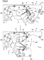
- FIG. 8 is a transition diagram showing a rotated state of each gear in the gear linkage mechanism 7 that occurs when the transport path 620 of the banknote storage device 6 is being opened and closed. Dash-dot line circles shown in FIG. 8 indicate the respective gears in the gear linkage mechanism 7.
- P81 indicates the state in which the transport path 620 of the banknote storage device 6 is closed
- P82 indicates the state in which the transport path 620 is open after it was closed.
- FIG. 8 shows the situation in which the first frame part 611 turns clockwise in FIG. 8 relative to the second frame part 612 (see a dash-dot line arrow) when the transport path 620 is being opened.
- the first idle gear 75 turns (i.e., revolves) clockwise around the center of rotation of the drum 63
- the gear linkage mechanism 7 has a preventing member 77.
- the preventing member 77 prevents the drum gear 72, engaging with the first idle gear 75, and the drum 63, to which the drum gear 72 is attached, from rotating clockwise in FIG. 8 when the first frame part 611 is turning in the direction in which the transport path 620 is opened.
- the preventing member 77 may be attached to, for example, the shaft 630 of the drum 63.
- the preventing member 77 may be configured using, for example, a one-way clutch to prevent the clockwise rotation of the drum gear 72 and the drum 63.
- the preventing member 77 may have the function of exerting resistance to the drum gear 72 and the drum 63 in the rotation direction when the transport path 620 is being opened.
- the preventing member 77 may exert resistance to the drum gear 72 and the drum 63 in the rotation direction such that the angle by which the drum gear 72 and the drum 63 rotate clockwise is smaller than the angle by which the first idle gear 75 revolves clockwise.
- the difference between the angle by which the first idle gear 75 revolves and the angle by which the drum gear 72 rotates is accommodated by the rotation (rotation on its axis) of the first idle gear 75.
- the first idle gear 75 which revolves around the center of rotation of the drum 63, rotates (rotates on its axis) clockwise as indicated by a solid line arrow in the lower diagram of FIG. 8 .
- the gear linkage mechanism 7 serves as a differential gear device.
- the first idle gear 75 forms a first member that is supported by the first frame part 611 and moves together with the first frame part 611 relative to the second frame part 612.
- the first reel gear 73 engaging with the first idle gear 75, rotates counterclockwise in FIG. 8 by the clockwise rotation on its axis of the first idle gear 75 (see a solid line arrow in the lower diagram of FIG. 8 ).
- the first reel gear 73 rotates counterclockwise, the first reel 621 rotates in the direction in which the first tape 641 is wound.
- the first reel gear 73 is an example of a second member that rotates the first reel 621 in the direction in which the first tape 641 is wound, in response to movement of the first idle gear 75, which is the first member, relative to the second frame part 612. Because the rotation of the drum 63 is prevented, the first tape 641 is substantially prevented from being unwound from the drum 63 or the first reel 621.
- the gear linkage mechanism 7 causes the first reels 621 to rotate in the direction in which the tape is wound, and therefore, the first tape 641 is pulled as indicated by a dashed line arrow in FIG. 8 , which substantially prevents the first tape 641 from becoming slack.
- the rotation of the drum gear 72 and the drum 63 is prevented, and therefore, the rotation of the second reel gear 74, engaging with the drum gear 72 through the second idle gear 76, is also prevented.
- the second tape 642 is also substantially prevented from becoming slack when the transport path 620 is being opened.
- the first reel gear 73 and the first reel 621 are disconnected from each other.
- the first idle gear 75 revolves counterclockwise around the center of rotation of the drum 63 while rotating on its axis.
- the first reel gear 73, engaging the first idle gear 75 also rotates.
- the first reel gear 73 and the first reel 621 have been disconnected from each other, and therefore, the first reel 621 does not rotate, and the first idle gear 75 and the first reel gear 73 idle.
- the first frame part 611 turns together with the first reel 621 and the first tape path 81, and therefore, the shape and length of the first tape path 81 are not or almost not changed. Therefore, when the transport path 620 is being closed, the first tape 641 is substantially prevented from becoming slack. In addition, when the transport path 620 is being closed, the rotation of the drum gear 72 is prevented, and therefore, the rotation of the second reel gear 74, engaging with the drum gear 72 through the second idle gear 76, is also prevented. Therefore, the second tape 642 is also substantially prevented from becoming slack when the transport path 620 is being closed.
- FIG. 9 shows an example configuration of the gear linkage mechanism 7 that is different from that of FIG. 8 .
- the gear linkage mechanism 7 shown in FIG. 9 causes the first idle gear 75, which is the first member, to revolve around the center of rotation of the drum 63 and thereby causes the drum gear 72 and the drum 63 to rotate in the tape winding direction.
- the gear linkage mechanism 7 of FIG. 9 has a second preventing member 78 that prevents the rotation of the first reel gear 73 and the first reel 621 when the first frame part 611 is turning in the direction in which the transport path 620 is opened.
- the second preventing member 78 prevents the rotation of the first reel gear 73 and the first reel 621 when the transport path 620 is transitioning from the closed state indicated by P91 to the open state indicated by P92.
- the second preventing member 78 may be attached to the first reel unit 651.
- the second preventing member 78 may be configured using, for example, a one-way clutch to prevent the rotation of the first reel gear 73 and the first reel 621.
- the second preventing member 78 may have the function of exerting resistance to the first reel gear 73 and the first reel 621 in the rotation direction when the transport path 620 is being opened.
- the second preventing member 78 may exert resistance to the first reel gear 73 and the first reel 621 in the rotation direction such that the angle by which the first reel gear 73 and the first reels 621 rotate is smaller than the angle by which the first idle gear 75 rotates on its axis. The difference between the angle by which the first idle gear 75 rotates on its axis and the angle by which the first reel gear 73 rotates is accommodated by the rotation of the drum gear 72.
- the second preventing member 78 prevents the rotation of the first reel gear 73 and the first reel 621, so that the rotation on its axis of the first idle gear 75, engaging with the first reel gear 73, is also prevented.
- the first idle gear 75 being prevented from rotating on its axis, revolves around the center of rotation of the drum 63, so that the drum gear 72 and the drum 63, engaging with the first idle gear 75, rotate clockwise as indicated by a solid line arrow in the lower diagram of FIG. 9 .
- the drum gear 72 is an example of a second member that rotates the drum 63 in the direction in which the first and second tapes 641 and 642 are wound, in response to movement of the first idle gear 75, which is the first member, relative to the second frame part 612.
- the gear linkage mechanism 7 also serves as a differential gear device when the transport path 620 is being opened. Note that the second preventing member 78 is attached to the shaft of the first idle gear 75.
- the second reel gear 74 and the second reel 622 are disconnected from each other.
- the drum gear 72 rotates clockwise
- the second idle gear 76 and the second reel gear 74 idle.
- the drum gear 72 and the drum 63 rotating clockwise in the lower diagram of FIG. 9 , the first and second tapes 641 and 642 are wound onto the drum 63. As described above, the rotation of the first reel 621 is prevented.
- the second reel 622 has been disconnected from the second reel gear 74.
- the first and second tapes 641 and 642 are pulled together as indicated by dashed line arrows in FIG. 9 , and therefore, the first and second tapes 641 and 642 are substantially prevented from becoming slack.
- the first reel gear 73 and the first reel 621 may be disconnected from each other.
- the drum gear 72, the second idle gear 76, and the second reel gear 74 do not rotate, and the first idle gear 75 revolves around the center of rotation of the drum 63 while rotating on its axis.
- the first idle gear 75 rotating on its axis, the first reel gear 73 also rotates.
- the first reel gear 73 and the first reels 621 have been disconnected from each other, and therefore, the first reel 621 does not rotate. Therefore, the first and second tapes 641 and 642 can be substantially prevented from becoming slack when the transport path 620 is being closed.
- banknote storage devices for example, when a tape failure such as a break in a tape occurs, the tape and a reel need to be replaced.
- a user in order to replace the tape and reel, a user needs to remove the banknote storage device from the banknote processing apparatus, and send the banknote storage device to a repair shop.
- the first and second reel units 651 and 652 are each removably attached to the frame 61.
- the first reel unit 651 has torque limiters 653 that limit the rotational torque of the first reels 621 in addition to the two first reels 621 and the first reel gear 73.
- the second reel unit 652 has torque limiters 654 that limit the rotational torque of the second reels 622 in addition to the two second reels 622 and the second reel gear 74.
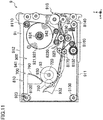
- the first reel unit 651 is removable from the first frame part 611. Specifically, as shown in FIG. 4 , a leading edge portion 6512 (an upper end portion in FIG. 4 ) of the first reel unit 651 is inserted into a bearing portion 613 of the first frame part 611, and a base end portion 6514 of the shaft 6511 is inserted into an opening portion (not shown) provided in the first frame part 611. The two portions of the first reel unit 651 are rotatably supported by the first frame part 611. Note that the first reel gear 73 is attached to an outer end portion of the first reel unit 651 that is located outward of the base end portion 6514.
- An R pin (snap pin) 6513 is attached to the shaft 6511 of the first reel unit 651.
- the R pin 6513 limits the movement of the first reel unit 651 in the axial direction, i.e. downward in the drawing sheet of FIG. 4 , relative to the first frame part 611.
- the attachment of the R pin 6513 keeps the first reel unit 651 supported by the first frame part 611.
- the user can move the first reel unit 651 in the axial direction relative to the first frame part 611.
- the leading edge portion 6512 of the first reel unit 651 is disconnected from the bearing portion 613 of the first frame part 611.
- the user can remove the first reel unit 651 from the first frame part 611 by disconnecting the base end portion 6514 of the shaft 6511 from the opening portion of the first frame part 611 (see arrows in FIG. 4 ).
- the first reel unit 651 is disconnected from the first frame part 611 in a direction away from the drum 63 (see dash-dot-dot lines in FIG. 4 or dash-dot-dot lines in FIG. 10 ).
- the shaft 6511 of the first reel unit 651 may be configured to be attached to the first frame part 611 using an E ring instead of the R pin.
- the second reel unit 652 is removable from the second frame part 612. Specifically, as shown in FIG. 4 , a leading edge portion 6522 of the second reel unit 652 is inserted into a bearing portion 614 of the second frame part 612, and a base end portion 6524 of the shaft 6521 is inserted into an opening portion (not shown) provided in the second frame part 612. The two portions of the second reel unit 652 are rotatably supported by the second frame part 612. Note that the second reel gear 74 is attached to an outer end portion of the second reel unit 652 that is located outward of the base end portion 6524.
- An R pin (snap pin) 6523 is attached to the shaft 6521 of the second reel unit 652.
- the R pin 6523 limits the movement of the second reel unit 652 in the axial direction, i.e. downward in the drawing sheet of FIG. 4 , relative to the second frame part 612.
- the attachment of the R pin 6523 keeps the second reel unit 652 supported by the second frame part 612.
- the user can move the second reel unit 652 in the axial direction relative to the second frame part 612.
- the leading edge portion 6522 of the second reel unit 652 is disconnected from the bearing portion 614 of the second frame part 612.
- the user can remove the second reel unit 652 from the second frame part 612 by disconnecting the base end portion 6524 of the shaft 6521 from the opening portion of the second frame part 612 (see arrows in FIG. 4 ).
- the second reel unit 652 is disconnected from the second frame part 612 in a direction away from the drum 63 (see dash-dot-dot lines in FIG. 4 or dash-dot-dot lines in FIG. 3 ).
- the shaft 6521 of the second reel unit 652 may be configured to be attached to the second frame part 612 using an E ring instead of the R pin.
- a maintenance person who maintains the banknote processing apparatus 1 can easily manually remove the first and second reel units 651 and 652 of the banknote storage device 6 from the banknote storage device 6.
- the tapes and reels of the banknote storage device can be replaced at a site where the banknote processing apparatus 1 is installed. The maintenance cost of the banknote storage device 6 is reduced.
- the maintenance person can remove the second reel unit 652 forward, i.e. leftward in the drawing sheet of FIG. 3 , from the banknote storage device 6, with the banknote storage device 6 having been pulled out of the banknote processing apparatus 1.
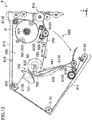
- the maintenance person can remove the first reel unit 651 backward, i.e. rightward in the drawing sheet of FIG. 10 , from the banknote storage device 6, while avoiding obstruction of the transport member 40, by turning the banknote storage device 6 upward around the second pivot shaft 623.
- the maintenance person can attach the second reel unit 652 to the banknote storage device 6 from the front of the banknote storage device 6.
- the maintenance person can also attach the first reel unit 651 to the banknote storage device 6 from the back of the banknote storage device 6.
- the maintenance person can replace the first and second reel units 651 and 652 without removing the banknote storage device 6 from the banknote processing apparatus 1.
- the leading edge of the first tape 641 and the leading edge of the second tape 642 need to be removed from the outer peripheral surface of the drum 63.
- the first tape 641 needs to be wrapped around the first and second tape pulleys 811 and 812, and the leading edge of the first tape 641 needs to be attached to the outer peripheral surface of the drum 63.
- the second tape 642 needs to be wrapped around the third tape pulley 821, the fourth tape pulley 822, and the fifth tape pulley 823, and the leading edge of the second tape 642 needs to be attached to the outer peripheral surface of the drum 63.
- the frame 61 of the banknote storage device 6 has the shaft 630 as the first pivot shaft, and the second pivot shaft 623.
- the inside of the banknote storage device 6 can be largely opened. Therefore, the maintenance person can insert their hand into the banknote storage device 6 from various directions such as directions indicated by open arrows shown in FIGS. 7 and 10 , and perform an operation of handling the tapes, with the banknote storage device 6 remaining attached to the banknote processing apparatus 1.
- the maintenance person can easily remove the leading edges of the first and second tapes 641 and 642 fixed to the outer peripheral surface of the drum 63, from the drum 63, and fix the leading edges of the first and second tapes 641 and 642 to the outer peripheral surface of the drum 63.
- the maintenance person can also easily wrap the first tape 641 around the first and second tape pulleys 811 and 812, and wrap the second tape 642 around the third tape pulley 821, the fourth tape pulley 822, and the fifth tape pulley 823.
- the banknote storage device 6 has high maintainability.
- a member having a greater stiffness than that of the first tape 641 may be attached to an end of the first tape 641.
- a member having a greater stiffness than that of the second tape 642 may be attached to an end of the second tape 642.
- the first reel unit 651 having the two first reels 621 and the second reel unit 652 having the two second reels 622 are attached to and detached from the frame 61.
- the first and second reels 621 and 622 are not configured to be individually attached to or detached from the frame 61 of the banknote storage device 6. The maintenance person can easily replace the tapes and reels.
- FIGS. 11-14 show a second example configuration of a banknote storage device 9.
- An input and output opening 910 through which a banknote 100 is input and output is provided in a side surface (a right surface in the example of FIG. 11 ) of the banknote storage device 9.
- the banknote storage device 9 includes a storage mechanism 900, and a frame 91 that accommodates the storage mechanism 900.
- the storage mechanism 900 is configured so that the banknote 100, which is sandwiched between tapes, is wound together with the tapes onto a drum 93.
- the storage mechanism 900 includes two first reels 921, two second reels 922, and the drum 93.
- the frame 91 has a first frame part 911 and a second frame part 912. Note that in FIG. 11 , only one reel is shown. This is because, as described below, a total of four reels are located at different positions in the Y direction, and at the same position in the X direction and the Z direction.
- the first frame part 911 is pivotably supported by the second frame part 912 at the position of a pivot shaft 923.
- the pivot shaft 923 is located at an opposite side portion from the input and output opening 910.
- the banknote storage device 9 is configured so that the entire transport path 920 can be opened.
- First tapes 941 unwound from the first reels 921 and second tapes 942 unwound from the second reels 922, stacking together, are wound onto the outer peripheral surface of the drum 93.
- the banknote 100 is sandwiched between the first tapes 941 and the second tapes 942.
- the two first reels 921 and the two second reels 922 are coaxially disposed.
- the first reels 921 and the second reels 922 are located at different positions in the Y direction, and at the same position in the X direction and the Z direction.
- a shaft 924 that supports the first reels 921 and the second reels 922 is supported by the second frame part 912.
- the shaft 924 supports the two first reels 921 and the two second reels 922 in a manner that allows the four reels to rotate separately.
- the two first reels 921 are spaced apart from each other in the Y direction.
- the two second reels 922 are also spaced apart in the Y direction.
- that second reel 922 is disposed closer to the center in the Y direction of the banknote storage device 9, and that first reel 921 is disposed on an outer side in the Y direction of the banknote storage device 9.
- that second reel 922 is disposed closer to the center in the Y direction of the banknote storage device 9, and that first reel 921 is disposed on an outer side in the Y direction of the banknote storage device 9.
- the first tape 941 unwound from the first reel 921 moves along a first tape path 810 to reach the drum 93.
- the second tape 942 unwound from the second reel 922 moves along a second tape path 820 to reach the drum 93.
- the first tape path 810 is formed by a first tape pulley 8110, a second tape pulley 8120, a third tape pulley 8130, a fourth tape pulley 8140, a fifth tape pulley 8150, a sixth tape pulley 8160, and a seventh tape pulley pair 8170.
- the second tape path 820 is formed by an eighth tape pulley 8210, a ninth tape pulley 8220, a tenth tape pulley 8230, and the seventh tape pulley pair 8170.
- the second tape 942 unwound from the second reel 922 is wrapped around the eighth tape pulley 8210, the ninth tape pulley 8220, the tenth tape pulley 8230, and the seventh tape pulley pair 8170 in this order, and reaches the drum 93.
- the eighth tape pulley 8210, the ninth tape pulley 8220, the tenth tape pulley 8230, and one of the seventh tape pulley pair 8170 are attached to the second frame part 912.
- the second frame part 912 forms a portion of the second tape path 820.
- the first tape 941 unwound from the first reel 921 is wrapped around the first tape pulley 8110, the second tape pulley 8120, the third tape 8130, the fourth tape pulley 8140, the fifth tape pulley 8150, the sixth tape pulley 8160, and the seventh tape pulley pair 8170 in this order, and reaches the drum 93.
- the first tape path 810 is formed to go around the drum 93.
- the first tape pulley 8110 is attached to the second frame part 912.
- the second tape pulley 8120, the third tape pulley 8130, the fourth tape pulley 8140, the fifth tape pulley 8150, the sixth tape pulley 8160, and one of the seventh tape pulley pair 8170 are attached to the first frame part 911.
- the first frame part 911 forms a portion of the first tape path 810.
- one of the seventh tape pulley pair 8170 is attached to a movable guide 932.
- the movable guide 932 is supported by the first frame part 911.
- a base end portion, i.e. a right end portion in FIG. 11 , of the movable guide 932 is attached to the first frame part 911 in a manner that allows the movable guide 932 to turn relative to the first frame part 911.
- the movable guide 932 is pressed clockwise in FIG. 11 by a pressing member (e.g., spring) (not shown).
- the movable guide 932 turns clockwise and counterclockwise, depending on the magnitude of the diameter of the drum 93.
- Each second tape pulley 8120 changes the movement direction of the first tape 941 between the X direction and the Z direction. As shown in FIG. 12 , the axis of rotation of each second tape pulley 8120 is tilted. More specifically, each second tape pulleys 8120 are located at the same or almost the same position in the Y direction as that of the first reel 921. The axis of rotation of each second tape pulley 8120 is tilted so that the outer side in the Y direction of the axis of rotation is lower than the inner side (closer to the center) in the Y direction of the axis of rotation. The axis of rotation of the second tape pulley 8120 disposed on the left side of the drawing sheet of FIG. 12 is tilted up to the right. The axis of rotation of the second tape pulley 8120 disposed on the right side of the drawing sheet of FIG. 12 is tilted down to the right.
- Each third tape pulley 8130 also changes the movement direction of the first tape 941 between the X direction and the Z direction. As shown in FIG. 12 , the axis of rotation of each third tape pulley 8130 is also tilted. Each third tape pulley 8130 is located at the same or almost same position in the Y direction as that of the second reel 922. The axis of rotation of each third tape pulley 8130 is parallel to the axis of rotation of the corresponding second tape pulley 8120. Specifically, the axis of rotation of each third tape pulley 8130 is tilted so that the outer side in the Y direction of the axis of rotation is lower than the inner side (closer to the center) in the Y direction of the axis of rotation.
- the axis of rotation of the third tape pulley 8130 disposed on the left side of the drawing sheet of FIG. 12 is tilted up to the right.
- the axis of rotation of the third tape pulley 8130 disposed on the right side of the drawing sheet of FIG. 12 is tilted down to the right.
- the first tape 941 unwound from the first reel 921 is wrapped around the second tape pulley 8120 and the third tape pulley 8130, so that the position in the Y direction of the first tape 941 is changed from the position of the first reel 921 to the position of the second reel 922. Thereafter, as described above, the first tape 941 is wrapped around the fourth tape pulley 8140, the fifth tape pulley 8150, and the sixth tape pulley 8160, and reaches the seventh tape pulley pair 8170. At this time, the first tape 941 is located at the same position in the Y direction as that of the second tape 942.
- the seventh tape pulley pair 8170 causes the first and second tapes 941 and 942 to stack together, and guides the first and second tapes 941 and 942 toward the outer peripheral surface of the drum 93.
- the banknote 100 is sandwiched between the first tape 941 and the second tape 942 at the position of the seventh tape pulley pair 8170.
- the first tape 941 unwound from the drum 93 is wrapped around the third tape pulley 8130 and the second tape pulley 8120, so that the position in the Y direction of the first tape 941 is changed from the position of the second reel 922 to the position of the first reel 921. Thereafter, the first tape 941 reaches the first reel 921 through the first tape pulley 8110.
- the banknote storage device 9 is also configured so that the tapes are wound when the transport path 920 is being opened.
- the banknote storage device 9 includes a drive mechanism 700.
- the drive mechanism 700 has a drum gear 720, an idle gear 750, and a frame gear 790.
- the drum gear 720 is attached to the drum 93.
- the frame gear 790 is attached to the first frame part 911.
- the idle gear 750 engages with the drum gear 720.
- the drive mechanism 700 is disposed extending from the first frame part 911 to the second frame part 912.
- the frame gear 790 is an example of a first member that is supported by the first frame part 911, and moves together with the first frame part 911 relative to the second frame part 912.
- the drum gear 720 and the idle gear 750 are an example of a second member that rotates the drum 63 in the tape winding direction in association with the movement of the frame gear 790, which is the first member, relative to the second frame part 912.
- the center of rotation of the drum gear 720 is coincident with the center of rotation of the drum 93.
- a one-way clutch (not shown) is interposed between the drum gear 720 and the drum 93.
- the one-way clutch transmits a rotary force to the drum 93, which is then rotated clockwise.
- the drum gear 720 rotates counterclockwise in FIG. 13
- the one-way clutch does not transmit a rotary force to the drum 93, which is therefore not rotated.
- the drum gear 720 idles.
- the drum gear 720 and the idle gear 750 engage with each other.
- the drum gear 720 rotates.
- the frame gear 790 does not engage with the idle gear 750.
- FIG. 13 when the first frame part 911 turns around the pivot shaft 923, the turning of the first frame part 911 around the pivot shaft 923 causes the frame gear 790 to engage with the idle gear 750.
- the frame gear 790 is a portion of a gear having the pivot shaft 923 as the center thereof. As indicated by a dash-dot line arrow in FIG. 13 , when the first frame part 911 rotates clockwise relative to the second frame part 912, the frame gear 790 turns around the pivot shaft 923 to engage with the idle gear 750. When the frame gear 790 engages with the idle gear 750, the idle gear 750 rotates counterclockwise as indicated by an arrow in FIG. 13 . As a result, the drum gear 720, engaging with the idle gear 750, rotates clockwise in FIG. 13 . The drum 93 rotates in the direction in which the first and second tapes 941 and 942 are wound.
- a preventing member prevents the rotation of the first and second reels 921 and 922.
- the first and second tapes 941 and 942 are pulled, and therefore, are substantially prevented from becoming slack.
- the frame gear 790 turns counterclockwise around the pivot shaft 923.
- the idle gear 750 engaging with the frame gear 790, rotates clockwise, and the drum gear 720 rotates counterclockwise.
- the above one-way clutch causes the drum gear 720 to idle, and therefore, the drum 63 does not rotate.
- the first frame part 911 turns together with a portion of the first tape path 810, and therefore, the length of the first tape path 810 is not or almost not changed. Therefore, when the transport path 920 is being closed, the first tape 941 is substantially prevented from becoming slack. In addition, when the transport path 920 is being closed, the rotation of the drum 93 is prevented, and therefore, the second tape 942 is also substantially prevented from becoming slack.
- the frame gear 790 does not engage with the idle gear 750, and therefore, has not an influence on the drum 93.
- the drive mechanism 700 can avoid an increase in the load of a motor for rotating the drum 93 when the banknote storage device 9 is in use.
- the movable guide 932 is pressed clockwise in FIG. 11 by the pressing member.
- the movable guide 932 presses the banknote 100, the first tapes 941, and the second tapes 942 which are wound around the drum 93.
- the movable guide 932 may be pressed clockwise by the pressing member. As a result, even when the transport path 920 is open, the movable guide 932 can press the banknote 100, the first tape 941, and the second tape 942.
- the banknote storage device 9 can maintain the stored state of the banknote 100.
- the movable guide 932 may be configured to allow the user to manually remove the pressing of the pressing member. If the user removes the pressing of the movable guide 932 before the transport path 920 is opened, the movable guide 932 is separated from the outer peripheral surface of the drum 93 when the transport path 920 is opened, as shown in, for example, FIG. 14 . For example, a failure that a portion of a banknote gets jammed between the movable guide 932 and the drum 93 when the user tires to remove the banknote, can be substantially prevented from occurring.
- the removal of the pressing of the movable guide 932 is not limited to manual removal.
- the banknote storage device 9 may be configured so that the pressing is removed in association with the turning of the first frame part 911 to open the transport path 920, and the pressing, having been removed, is resumed in association with the turning of the first frame part 911 to close the transport path 920.
- the timing with which the pressing of the movable guide 932 is removed is not particularly limited.
- the movable guide 932 may be pressed clockwise by the pressing member.
- the movable guide 932 can be separated from the outer peripheral surface of the drum 93. Note that the user performs an operation of resuming the pressing, having been removed, before or after closing the transport path 920.
- the banknote storage device 9 may be configured so that the pressing, having been removed, is resumed in association with the turning of the first frame part 911 to close the transport path 920.
- FIG. 15 shows an example configuration of a drive mechanism 701 that is different from that of FIG. 11 .
- the drive mechanism 701 of FIG. 15 substantially prevents the first and second tapes 941 and 942 from becoming slack by rotating the first and second reels 921 and 922 when the transport path 920 is being opened.
- the drive mechanism 701 has the above frame gear 790, a first gear 751 that engages with the frame gear 790, a reel gear 730 attached to the reel shaft 924, and a second gear 752 that engages with the reel gear 730.
- the first gear 751 and the second gear 752 are linked together by a belt 753.
- the belt 753 transmits a rotary force between the first gear 751 and the second gear 752.
- the drive mechanism 701 is disposed extending from the first frame part 911 to the second frame part 912.
- the frame gear 790 is an example of a first member that is supported by the first frame part 911, and moves together with the first frame part 911 relative to the second frame part 912.
- the first gear 751, the second gear 752, the belt 753, and the reel gear 730 are an example of a second member that rotates the first and second reels 921 and 922 in the tape winding direction in association with the movement of the frame gear 790, which is the first member, relative to the second frame part 912.
- the frame gear 790 does not engage with the first gear 751.
- the first gear 751 rotates counterclockwise as indicated by an arrow shown in the lower diagram of FIG. 15 .
- the second gear 752 also rotates counterclockwise through the belt 753.
- the first and second reels 921 and 922 rotate in the direction in which the first and second tapes 941 and 942 are wound.
- a preventing member prevents the rotation of the drum 93.
- the first and second tapes 941 and 942 are pulled, and therefore, are substantially prevented from becoming slack.
- the frame gear 790 turns counterclockwise around the pivot shaft 923.
- the first and second tapes 941 and 942 can be substantially prevented from becoming slack when the transport path 920 is being closed.
- the tape-type storage units 51 of the banknote processing apparatus 1 may have the same configuration as that of the banknote storage device 6 of FIGS. 3-6 or the banknote storage device 9 of FIGS. 11 and 12 .
- the tape-type storage units 51 included in the storage unit 5 are an example sheet storage device.
- the above banknote storage devices have two first tapes and two second tapes
- the number of tapes in a banknote storage device to which the technology disclosed herein is applicable is not particularly limited.
- the number of tapes may be appropriately determined.
- the banknote storage devices store banknotes sandwiched between the first and second tapes
- the configuration of the tape-type banknote storage device for storing banknotes is not particularly limited.
- the tape-type banknote storage device may have various configurations.
- the drum may be supported by the first frame part.
- the banknote storage devices may further have, for example, a third frame part.
- the banknote storage devices may be configured so that the drum is supported by the third frame part.
- the technology disclosed herein is not limited to use in a banknote processing apparatus and a banknote storage device.
- the technology disclosed herein is widely applicable to, for example, sheet processing apparatuses and sheet storage devices that process sheets including checks, coupons, and various securities.
Landscapes
- Engineering & Computer Science (AREA)
- Mechanical Engineering (AREA)
- Physics & Mathematics (AREA)
- General Physics & Mathematics (AREA)
- Discharge By Other Means (AREA)
- Delivering By Means Of Belts And Rollers (AREA)
Abstract
Description
- The technology disclosed herein relates to sheet storage devices and sheet processing apparatuses.
- Japanese Patent Publication No.
2013-25707 - When a banknote jam or the like occurs, a user can open the transport path of the temporary storage unit.
- However, in the temporary storage unit described in the publication above, when the upper guide turns around the retraction shaft, only a tape pulley attached to the upper guide is moved away from the center of the drum without the movement of the drum and a tape reel. As a result, the tape path between the drum and the tape reel is shortened, and therefore, the tape becomes slack between the drum and the tape reel.
- In order to substantially prevent the slacking of the tape, a torsion spring is attached to the tape reel in the temporary storage unit described in the publication above. The torsion spring presses the tape reel in the direction in which the tape is wound. However, the torsion spring of the publication above presses the tape reel to exert tension on the tape even when the transport path is not open. Therefore, in the temporary storage unit described in the publication above, it is necessary to adjust the pressing force of the torsion spring so that the drum is not rotated by the pressing force of the torsion spring, or a locking mechanism or torque limiter mechanism for limiting the rotation of the drum needs to be provided in the temporary storage unit. Such a cumbersome adjustment and a complicated structure are drawbacks of the temporary storage unit of the publication above.
- The technology disclosed herein simplifies the configuration of a sheet storage device in which the transport path can be opened.
- Specifically, the technology disclosed herein is directed to a sheet storage device. The sheet storage device includes a reel around which a tape is wound, a drum onto which a sheet is wound together with the tape, an input and output opening through which the sheet is passed, and a frame configured to form at least a portion of a transport path on which the sheet is transported from the input and output opening to the drum.
- The frame has a first frame part and a second frame part. The first frame part and the second frame part are configured to move relative to each other to switch between a state in which the transport path is formed and a state in which at least a portion of the transport path is open.
- The first frame part supports the reel, and forms a tape path extending from the reel to the drum. The first frame part moves together with the reel and the tape path relative to the second frame part.
- With this configuration, the tape is substantially prevented from becoming stack when a user opens at least a portion of the transport path. A part such as a torsion spring is not required, resulting in a simpler configuration of the sheet storage device.
- The first frame part may turn together with the reel and the tape path around the center of rotation of the drum relative to the second frame part.
- With this configuration, the tape is substantially prevented from being pulled out of the drum or the reel when the first frame part turns, which is beneficial for prevention of slacking of the tape.
- The sheet storage device may include a second reel around which a second tape is wound. The second frame part may form a second tape path extending from the second reel to the drum. The second frame part may move together with the second tape path relative to the first frame part.
- The second frame part may support the second reel. The second frame part may move together with the second reel and the second tape path relative to the first frame part.
- With this configuration, the second tape is substantially prevented from being pulled out of the drum or the second reel, and therefore, the second tape is substantially prevented from becoming slack.
- The second frame part may support the drum.
- With this configuration, the drum, the second reel, and the second tape path are all supported by the second frame part. Therefore, when the second frame part moves relative to the first frame part, the shape and length of the second tape path are not or almost not changed.
- The drum may be disposed between the reel and the second reel at least in a closed state of the transport path.
- This configuration is beneficial for making the sheet storage device more compact.
- The sheet storage device may include a movable guide configured to be brought into contact with the tape wound around the drum, and move depending on a change in the magnitude of the diameter of the drum. A winding position where the tape and the second tape may be wound onto the drum is located between the drum and the reel. The movable guide may be disposed between the winding position and the reel.
- With this configuration, a space for accommodating the movable guide does not need to be provided between the drum and the second reel. Such an accommodation space can be saved, and therefore, the diameter of the drum can be proportionately increased. The size and capacity of the sheet storage device can both be increased.
- A sheet processing apparatus herein disclosed includes the above sheet storage device.
- The sheet processing apparatus may include a housing configured to house the sheet storage device, and a transport member disposed in the housing and coupled to the input and output opening of the sheet storage device, and configured to transport the sheet toward the input and output opening or from the input and output opening. The first frame part and the second frame part may form the input and output opening. A part forming the input and output opening of the first frame part or the second frame part may be linked to the transport member with the first frame part and the second frame part having moved relative to each other to open the transport path.
- With this configuration, when a user opens at least a portion of the transport path of the sheet storage device in the case of sheet jam or the like, a sheet is substantially prevented from dropping from the open transport path.
- The sheet storage device may have a first pivot shaft configured to allow the first frame part and the second frame part to move relative to each other, and a second pivot shaft configured to allow the sheet storage device to move relative to the transport member.
- With this configuration, the transport path can be largely opened in the configuration in which the part forming the input and output opening of the first frame part, or the part forming the input and output opening of the second frame part, is linked to the transport member.
- Another sheet storage device disclosed herein includes a reel around which a tape is wound, a drum onto which a sheet is wound together with the tape, an input and output opening through which the sheet is passed, and a frame configured to form at least a portion of a transport path on which the sheet is transported from the input and output opening to the drum. The frame has a first frame part and a second frame part. The first frame part and the second frame part are configured to move relative to each other to switch between a state in which the transport path is formed and a state in which at least a portion of the transport path is open. The first frame part forms at least a portion of a tape path extending from the reel to the drum, and moves together with the tape path relative to the second frame part.
- The sheet storage device further includes a drive mechanism disposed extending from the first frame part to the second frame part. The drive mechanism rotates the drum or the reel in a direction in which the tape is wound, in association with the movement of the first frame part relative to the second frame part.
- With this configuration, when the first frame part moves relative to the second frame part, the tape is wound onto the drum or the reel. In the sheet storage device, a part for exerting tension on the tape, such as a torsion spring, is not required, resulting in a simpler configuration.
- The drive mechanism may have at least a first member supported by the first frame part, and configured to move together with the first frame part relative to the second frame part, and a second member configured to rotate the drum or the reel in a direction in which the tape is wound, in response to the movement of the first member relative to the second frame part.
- With this configuration, the drive mechanism can rotate the drum or the reel when the first frame part moves relative to the second frame part.
- The reel may be supported by the first frame part or the second frame part. The drum may be supported by the second frame part or the first frame part. The reel and the drum may be coupled together through the drive mechanism.
- The first frame part may support the reel, and turn together with the reel and the tape path around the center of rotation of the drum relative to the second frame part. The second frame part may support the drum. The drive mechanism may have a drum gear linked to the drum, a reel gear linked to the reel, and an idle gear engaging with both the drum gear and the reel gear. The idle gear may be the first member, and the idle gear may revolve around the center of rotation of the drum with the idle gear engaging with both the drum gear and the reel gear during the turning of the first frame part relative to the second frame part.
- With this configuration, when the first frame part and the second frame part turn relative to each other, the plurality of gears of the drive mechanism are kept linked together to rotate the drum or the reel.
- The drive mechanism may have a preventing member configured to prevent rotation of the drum gear and the drum during the turning of the first frame part relative to the second frame part in a direction in which the transport path is opened. During the turning of the first frame part relative to the second frame part in the direction in which the transport path is opened, the idle gear may revolve around the center of rotation of the drum while rotating on an axis thereof, whereby the reel rotates in the winding direction of the tape through the reel gear.
- With this configuration, the tape is substantially prevented from becoming slack due to the turning of the reel when at least a portion of the transport path is opened.
- The drive mechanism may have a second preventing member configured to prevent rotation of the reel gear and the reel during the turning of the first frame part relative to the second frame part in a direction in which the transport path is opened. During the turning of the first frame part relative to the second frame part in the direction in which the transport path is opened, the idle gear may revolve around the center of rotation of the drum without rotating on an axis thereof, which causes the drum gear to rotate, whereby the drum rotates in the winding direction of the tape.
- With this configuration, the tape is substantially prevented from becoming slack due to the rotation of the drum when at least a portion of the transport path is opened.
- The reel, the drum, or the reel and the drum, may be supported by the second frame part. The drive mechanism may be coupled to the reel or the drum.
- With this configuration, when the first frame part moves relative to the second frame part, the drive mechanism rotates the reel or the drum so that the tape is wound.
- The drum may be supported by the second frame part. The drive mechanism may have a drum gear linked to the drum, and a frame gear supported by the first frame part. The frame gear may be the first member. The drum gear may rotate the drum in a direction in which the tape is wound, in response to the movement of the frame gear relative to the second frame part.
- The reel may be supported by the second frame part. The drive mechanism may have a reel gear linked to the reel, and a frame gear linked to the first frame part. The frame gear may be the first member. The reel gear may rotate the reel in a direction in which the tape is wound, in response to the movement of the frame gear relative to the second frame part.
- The first frame part may turn around a pivot shaft relative to the second frame part. The frame gear may turn around the pivot shaft in association with the turning of the first frame part relative to the second frame part. The drive mechanism may remove linkage between the frame gear and the second member in a state in which the first frame part and the second frame part forms the transport path. During the turning of the first frame part relative to the second frame part, the drive mechanism may link the frame gear and the second member together to rotate the reel or the drum.
- With this configuration, the drive mechanism does not have an influence on the rotation of the drum or the reel when the sheet storage device is in use.
-
-
FIG. 1 is a perspective view illustrating an appearance of a banknote processing apparatus. -
FIG. 2 is a schematic diagram showing an example internal configuration of a banknote processing apparatus. -
FIG. 3 is a cross-sectional view showing an example internal configuration of a banknote storage device as viewed from a side thereof. -
FIG. 4 is a bottom view showing an example configuration of a banknote storage device. -
FIG. 5 is a diagram including a plan view (upper diagram) and a side view (lower diagram) showing a configuration at and near a position where a tape is wound around a drum. -
FIG. 6 is a perspective view showing an example configuration of a gear linkage mechanism in a banknote storage device. -
FIG. 7 is a diagram showing a state in which a transport path of a banknote storage device is open, corresponding toFIG. 3 . -
FIG. 8 is a transition diagram showing rotated states of a drum and a reel that occur when a transport path of a banknote storage device is opened. -
FIG. 9 is a transition diagram showing rotated states of a drum and a reel that occur when a transport path of a banknote storage device is opened, in a configuration different from that ofFIG. 8 . -
FIG. 10 is a diagram for describing removal of a reel unit of a banknote storage device, corresponding toFIG. 3 . -
FIG. 11 is a cross-sectional view showing an internal configuration of a banknote storage device according to a second example configuration. -
FIG. 12 is a side view showing a configuration of a tape path of the banknote storage device of the second example configuration. -
FIG. 13 is a diagram showing a state in which the tape path of the banknote storage device of the second example configuration is open, corresponding toFIG. 11 . -
FIG. 14 is a diagram showing a state in which the tape path of the banknote storage device of the second example configuration is open, and a pressing force to a movable guide has been removed, corresponding toFIG. 11 . -
FIG. 15 is a transition diagram showing rotated states of a drum and a reel that occur when a transport path of a banknote storage device according to variation is opened. - Embodiments of a sheet storage device and a sheet processing apparatus will now be described in detail with reference to the accompanying drawings. In the description that follows, an example sheet storage device and an example sheet processing apparatus are described.
-
FIG. 1 shows abanknote processing apparatus 1 as a sheet processing apparatus. Thebanknote processing apparatus 1, which is installed in, for example, a financial institution, such as a bank, executes various processes including a deposit process and a withdrawal process. Note that thebanknote processing apparatus 1 may be installed and used in, for example, the back office of a retail store, in addition to installation in a financial institution. -
FIG. 1 shows an example appearance of thebanknote processing apparatus 1.FIG. 2 shows an example internal structure of thebanknote processing apparatus 1. In the description that follows, for the sake of convenience, as shown inFIG. 1 , a direction from the back to front of thebanknote processing apparatus 1 is represented by X direction, a direction from left to right that is defined from the point of view of an observer facing the front side of thebanknote processing apparatus 1 is represented by Y direction, and a direction from the bottom to top of thebanknote processing apparatus 1 is represented by Z direction. - The
banknote processing apparatus 1 processes loose banknotes. Thebanknote processing apparatus 1 has aprocessing unit 11 located in an upper portion thereof and asafe unit 13 located in a lower portion thereof. - The
processing unit 11 includes adeposit unit 21, a first dispenseunit 22, asecond withdrawal unit 23, arecognition unit 24, atemporary storage unit 3, a portion of atransport unit 4, and acontrol unit 25, which are disposed in ahousing 111. As indicated by dash-dot lines inFIG. 2 , a user can pull, out of thehousing 111, thedeposit unit 21, thefirst withdrawal unit 22, thesecond withdrawal unit 23, therecognition unit 24, thetemporary storage unit 3, and a portion of thetransport unit 4 by shifting them in the X direction. - The
deposit unit 21 is a part into which banknotes are put in, for example, the deposit process. Thedeposit unit 21 has aninlet 211. Theinlet 211 is an opening in an upper surface of thehousing 111. The user puts banknotes into thedeposit unit 21 through theinlet 211. Thedeposit unit 21 has a mechanism that feeds banknotes loaded therein into the apparatus one by one. - The first and
second withdrawal units second withdrawal units second withdrawal units second withdrawal units second withdrawal units respective outlets outlets housing 111. The user can take out banknotes gathered in thefirst withdrawal unit 22 through theoutlet 221. The user can take out banknotes gathered in thesecond withdrawal unit 23 through theoutlet 231. - The
recognition unit 24 is disposed on aloop transport path 41 described below. Therecognition unit 24 recognizes at least the authenticity, denomination, and fitness of each banknote transported on theloop transport path 41. - The
temporary storage unit 3 includes abanknote storage device 6. Thetemporary storage unit 3 can take in and store banknotes therein, and feed out banknotes stored therein. Thetemporary storage unit 3 temporarily stores banknotes to be deposited, in, for example, the deposit process. When the deposit process is accepted, thetemporary storage unit 3 feeds out the stored banknotes. The banknotes fed out are stored in astorage unit 5 described below. Thetemporary storage unit 3 can also be used for other purposes. - The
temporary storage unit 3 is located in a front portion of thehousing 111. Thetemporary storage unit 3 is removably disposed in thehousing 111. Thebanknote processing apparatus 1 can operate without thetemporary storage unit 3. Thebanknote storage device 6 included in thetemporary storage unit 3 is described in detail below. - The
safe unit 13 includes asafe housing 131. In thesafe housing 131, thestorage unit 5 and a portion of thetransport unit 4 are disposed. Thesafe housing 131 protects thestorage unit 5 at a predetermined protection level or higher. The protection level of thesafe housing 131 is higher than that of thehousing 111. - A
door 132 is attached to a front portion of thesafe housing 131. Alock unit 133 is attached to thedoor 132. The user can open thedoor 132 by entering a preset password into thelock unit 133. - The
storage unit 5 has a plurality of tape-type storage units 51. The illustratedbanknote processing apparatus 1 has a total of 10 tape-type storage units 51. The tape-type storage units 51 are disposed in thesafe housing 131 and aligned in a vertical direction and in a horizontal direction. Note that the number and arrangement of the tape-type storage units 51 are not particularly limited. - Each tape-
type storage unit 51 is configured so that banknotes can be taken in and stored therein, and banknotes stored therein can be fed out. - The
transport unit 4 has a transport path. Thetransport unit 4 is configured to transport banknotes one by one on the transport path with, for example, a longer side of each banknote facing forward and the banknotes spaced apart from each other. Although not shown, thetransport unit 4 is configured by a combination of a number of rollers, a plurality of belts, a motor for driving these components, and a plurality of guides. - The
transport unit 4 has theloop transport path 41 provided in thehousing 111. As described above, theloop transport path 41 passes through therecognition unit 24. Thetransport unit 4 transports banknotes along theloop transport path 41 clockwise and counterclockwise inFIG. 2 . - The
deposit unit 21, thefirst withdrawal unit 22, and thesecond withdrawal unit 23 are coupled to theloop transport path 41 through coupling paths. Thetemporary storage unit 3 is also coupled to theloop transport path 41. - Although not shown, a diverter for changing destinations of banknotes is provided between the
loop transport path 41, and thedeposit unit 21, thefirst withdrawal unit 22, thesecond withdrawal unit 23, and thetemporary storage unit 3. - The
transport unit 4 has atransport module 42 in thesafe housing 131. Thetransport module 42 is removable from thesafe housing 131. Thetransport module 42 has a transport path that links theloop transport path 41 and each tape-type storage unit 51 together. Although not shown, thetransport module 42 has a diverter that changes transport destinations of banknotes. - Although not shown, a tracking sensor that detects passage of banknotes is disposed at various portions of the transport path. The
transport unit 4 transports banknotes to a predetermined transport destination in response to an instruction from thecontrol unit 25, by controlling each diverter on the basis of detection signals of the tracking sensors. - Operations of the
banknote processing apparatus 1 during execution of the deposit process and the withdrawal process will now be briefly described. - The user puts banknotes to be deposited into the
deposit unit 21. Thedeposit unit 21 feeds the banknotes one by one into the apparatus. Thetransport unit 4 transports the banknote to therecognition unit 24. Therecognition unit 24 recognizes the banknote. After the banknote has been passed through therecognition unit 24, thetransport unit 4 transports the banknote through thetransport module 42 to one of the plurality of tape-type storage units 51. The tape-type storage unit 51 stores the banknote. If all banknotes that can be deposited have been stored in the tape-type storage units 51, the deposit process is ended. - Note that in the case where the
temporary storage unit 3 is used in the deposit process, thetransport unit 4 transports banknotes that have been passed through therecognition unit 24, to thetemporary storage unit 3. Thetemporary storage unit 3 stores the banknotes. After the amount of the deposit has been accepted, thetemporary storage unit 3 feeds out the stored banknotes. Thetransport unit 4 transports each of the banknotes fed out by thetemporary storage unit 3, to one of the plurality of tape-type storage units 51 through thetransport module 42. - The tape-
type storage unit 51 feeds out banknotes to be withdrawn in the withdrawal process. Thetransport unit 4 transports the banknotes fed out by the tape-type storage unit 51, from thetransport module 42 through theloop transport path 41 to therecognition unit 24. Therecognition unit 24 recognizes the banknotes. Thetransport unit 4 transports the recognized banknotes to thefirst withdrawal unit 22 and/or thesecond withdrawal unit 23. If all banknotes to be withdrawn have been withdrawn to thefirst withdrawal unit 22 or thesecond withdrawal unit 23, the withdrawal process is ended. -
FIGS. 3-6 show an example configuration of thebanknote storage device 6. As described above, thebanknote storage device 6 is included in thetemporary storage unit 3. -
FIG. 3 is a cross-sectional view of thebanknote storage device 6 as viewed from a side thereof.FIG. 4 is a bottom view of thebanknote storage device 6. InFIG. 3 , solid lines indicate the state in which the storage amount of thebanknote storage device 6 is zero, i.e. no banknotes are stored in thebanknote storage device 6. InFIG. 3 , dash-dot lines indicate the state in which the storage amount of thebanknote storage device 6 is maximum. - In
FIG. 3 , areference character 40 indicates a transport member. Thetransport member 40 is disposed in thehousing 111, and forms a portion of the aboveloop transport path 41 and coupling path. An input andoutput opening 610 through which banknotes are input and output is provided in a side surface (right surface in the example ofFIG. 3 ) of thebanknote storage device 6. Thetransport member 40 is coupled to the input andoutput opening 610 of thebanknote storage device 6. More specifically, the input andoutput opening 610 is provided with a comb tooth-shaped coupling guide (not shown). In addition, thetransport member 40 is provided with a comb tooth-shaped coupling guide (not shown). Specifically, a comb tooth-shaped coupling guide is provided at an end portion of the coupling path extending from theloop transport path 41 to thebanknote storage device 6. The comb tooth-shaped portions of the two coupling guides overlap each other, so that thetransport member 40 is coupled to the input andoutput opening 610 of thebanknote storage device 6. Thetransport member 40 transports banknotes toward the input andoutput opening 610, so that the banknotes pass through the input andoutput opening 610 and then enter thebanknote storage device 6. Thetransport member 40 also transports banknotes that have been output from thebanknote storage device 6 through the input andoutput opening 610. - The
banknote storage device 6 includes astorage mechanism 600, and aframe 61 that accommodates thestorage mechanism 600. Thestorage mechanism 600 is configured so that a banknote 100 (seeFIG. 5 ) sandwiched between two tapes is wound together with the tapes onto thedrum 63. Thebanknote 100 is wound onto thedrum 63 with the longer sides of thebanknote 100 parallel to the axis of rotation of thedrum 63. Thestorage mechanism 600 has afirst reel 621, asecond reel 622, and thedrum 63. Theframe 61 has afirst frame part 611 and asecond frame part 612. - An end of a
first tape 641 is fixed to thefirst reel 621, and thefirst tape 641 is wound around thefirst reel 621. An end of asecond tape 642 is fixed to thesecond reel 622, and thesecond tape 642 is wound around thesecond reel 622. The other end of thefirst tape 641 and the other end of thesecond tape 642 are each fixed to an outer peripheral surface of thedrum 63. - The
first reel 621 is located closer to the input andoutput opening 610 than is thedrum 63. Thesecond reel 622 is located further from the input andoutput opening 610 than is thedrum 63. As shown inFIG. 3 , in the state in which thefirst frame part 611 and thesecond frame part 612 form atransport path 620 described below, thefirst reel 621 and thesecond reel 622 are located facing each other with thedrum 63 interposed therebetween. - As shown in
FIG. 4 , there are two of thefirst reels 621 that are spaced apart from each other in the Y direction. The twofirst reels 621 and ashaft 6511 are integrated together to form afirst reel unit 651. Theshaft 6511 supports the twofirst reels 621 separately, and serves as the center of rotation of thefirst reels 621. Thefirst reels 621 are supported by theshaft 6511 through, for example, a torque limiter. Afirst reel gear 73 described below is attached to the base end of thefirst reel unit 651. - Likewise, there are two of the
second reels 622 that are spaced apart from each other in the Y direction. The twosecond reels 622 and ashaft 6521 are integrated together to form asecond reel unit 652. Theshaft 6521 supports the twosecond reels 622 separately, and serves as the center of rotation of thesecond reels 622. Thesecond reels 622 are supported by theshaft 6521 through, for example, a torque limiter. Asecond reel gear 74 described below is attached to the base end of thesecond reel unit 652. - The
first reel unit 651 is supported by thefirst frame part 611. The twofirst reels 621 are supported by thefirst frame part 611. Thefirst reels 621 rotate in the direction in which thefirst tapes 641 are unwound (clockwise inFIG. 3 ) and in the direction in which thefirst tapes 641 are wound (counterclockwise inFIG. 3 ). The twofirst reels 621 independently rotate depending on the tension of thefirst tapes 641. - The
second reel unit 652 is supported by thesecond frame part 612. The twosecond reels 622 are supported by thesecond frame part 612. Thesecond reels 622 rotate in the direction in which thesecond tapes 642 are unwound (clockwise inFIG. 3 ) and in the direction in which thesecond tapes 642 are wound (counterclockwise inFIG. 3 ). The twosecond reels 622 independently rotate depending on the tension of thesecond tapes 642. - As shown in
FIG. 3 , in the state in which thefirst frame part 611 and thesecond frame part 612 form atransport path 620 described below, thedrum 63 is disposed between thefirst reel 621 and thesecond reel 622. Ashaft 630 of thedrum 63 is supported by thesecond frame part 612. The center of rotation of thedrum 63 extends in the Y direction. The center of rotation of thedrum 63, the center of rotation of thefirst reel 621, and the center of rotation of thesecond reel 622 are parallel to each other. Thedrum 63 rotates in the direction in which thebanknote 100 and the tapes are wound and in the direction in which thebanknote 100 and the tapes are unwound. In the example ofFIG. 3 , the direction in which thebanknote 100 and the tapes are wound onto thedrum 63 is the clockwise direction, and the direction in which thebanknote 100 and the tapes are unwound is the counterclockwise direction. - The
first tape 641 unwound from thefirst reel 621 is moved along afirst tape path 81 to reach thedrum 63. Thefirst tape path 81 is formed by afirst tape pulley 811 and asecond tape pulley 812. The first and second tape pulleys 811 and 812 are both supported by thefirst frame part 611. - The
second tape 642 unwound from thesecond reel 622 is moved along asecond tape path 82 to reach thedrum 63. Thesecond tape path 82 is formed by athird tape pulley 821, afourth tape pulley 822, and afifth tape pulley 823. Thethird tape pulley 821, thefourth tape pulley 822, and thefifth tape pulley 823 are all supported by thesecond frame part 612. - The
first tape pulley 811 is located closer to thefirst reel 621 than is thesecond tape pulley 812. Thesecond tape pulley 812 is located closer to thedrum 63 than is thefirst tape pulley 811. Thesecond tape pulley 812 is located on thebanknote transport path 620. Thefirst tape 641 unwound from thefirst reel 621 is wrapped around thefirst tape pulley 811 and thesecond tape pulley 812 in this order. Thefirst tape 641 wrapped around thesecond tape pulley 812 is moved along thetransport path 620 to reach thedrum 63. - The
third tape pulley 821 is located closer to thesecond reel 622 than are thefourth tape pulley 822 and thefifth tape pulley 823. Thefourth tape pulley 822 is disposed between thethird tape pulley 821 and thefifth tape pulley 823. Thefifth tape pulley 823 is located on thetransport path 620. Thefifth tape pulley 823 and thesecond tape pulley 812 face each other with thetransport path 620 interposed therebetween. - The
second tape 642 unwound from thesecond reel 622 is wrapped around thethird tape pulley 821, thefourth tape pulley 822, and thefifth tape pulley 823 in this order. Thesecond tape 642 wrapped around thefifth tape pulley 823 is moved along thetransport path 620, facing thefirst tape 641, to reach thedrum 63. - A winding
position 631 where thefirst tape 641 and thesecond tape 642 are wound onto thedrum 63, is located between thedrum 63 and thefirst reel 621. Thesecond tape 642 goes around thedrum 63 after having been unwound from thesecond reel 622 to reach the windingposition 631. The first andsecond tapes drum 63. Note that thefirst tape pulley 811, thesecond tape pulley 812, thethird tape pulley 821, thefourth tape pulley 822, and thefifth tape pulley 823 do not necessarily need to be a pulley, and may be a guide that changes the movement direction of the tape. - As indicated using an imaginary line in
FIG. 3 , thetransport path 620 is formed between the input andoutput opening 610 and thedrum 63. Thetransport path 620 is formed by an input and outputopening roller pair 66, afirst belt 671 and asecond belt 672, afirst guide member 681 and asecond guide member 682, and agrip roller pair 69. Thebanknote 100 is transported along thetransport path 620 in a direction from the input andoutput opening 610 toward thedrum 63 or in a direction from thedrum 63 toward the input andoutput opening 610. - The input and output
opening roller pair 66 includes a first input andoutput opening roller 661 and a second input andoutput opening roller 662. The first input andoutput opening roller 661 is supported by thefirst frame part 611, and the second input andoutput opening roller 662 is supported by thesecond frame part 612. The input and outputopening roller pair 66 feeds thebanknote 100 into thebanknote storage device 6 through the input andoutput opening 610, and sends out thebanknote 100 from the inside of thebanknote storage device 6 through the input andoutput opening 610. The first input andoutput opening roller 661 may be supported by thetransport member 40. - The
first belt 671 is wrapped around two rollers. Thefirst belt 671 is supported by thefirst frame part 611. Thesecond belt 672 is wrapped around two rollers different from those around which thefirst belt 671 is wrapped. Thesecond belt 672 is supported by thesecond frame part 612. - The
first belt 671 is moved along thetransport path 620 of thebanknote 100. Thesecond belt 672 is also moved along thetransport path 620. Thefirst belt 671 and thesecond belt 672 face each other with thebanknote 100 sandwiched therebetween in the thickness direction. The first andsecond belts banknote 100 from the input andoutput opening 610 toward thedrum 63 or from thedrum 63 toward the input andoutput opening 610. -
FIG. 5 shows a portion where thegrip roller pair 69 is disposed near thedrum 63. The lower diagram ofFIG. 5 shows that portion as viewed from a side thereof. The upper diagram ofFIG. 5 shows that portion as viewed from above. There are two of the grip roller pairs 69 that are spaced apart from each other in the Y direction. The two grip roller pairs 69 each sandwich a predetermined portion in the longer side orientation of thebanknote 100, and transport thebanknote 100 from the input andoutput opening 610 toward thedrum 63 or from thedrum 63 toward the input andoutput opening 610. - More specifically, the
grip roller pair 69 includes afirst grip roller 691 and asecond grip roller 692. Thefirst grip roller 691 and thesecond grip roller 692 face each other. - The
first grip roller 691 and thesecond tape pulley 812 are coaxially disposed. Thefirst grip roller 691 is supported by thefirst frame part 611. Thefirst grip roller 691 has a greater diameter than that of thesecond tape pulley 812. Thefirst grip roller 691 is also located closer to the center of thedrum 63 than is thesecond tape pulley 812 in the direction in which the axis of thedrum 63 extends. - The
second grip roller 692 and thefifth tape pulley 823 are coaxially disposed. Thesecond grip roller 692 is supported by thesecond frame part 612. Thesecond grip roller 692 has a greater diameter than that of thefifth tape pulley 823. Thesecond grip roller 692 is also located closer to the center of thedrum 63 than is thefifth tape pulley 823 in the direction in which the axis of thedrum 63 extends. - The
first grip roller 691 is different from thesecond grip roller 692 in that a distance L1 between the center of rotation of thedrum 63 and thefirst grip roller 691 is longer than a distance L2 between the center of rotation of thedrum 63 and thesecond grip roller 692. In addition, the diameter of thesecond grip roller 692 is smaller than that of thefirst grip roller 691. Note that the diameter of thefifth tape pulley 823 is smaller than that of thesecond tape pulley 812. - Here, a dash-dot line circle shown in
FIG. 5 indicates the position of the outer periphery of thedrum 63 in the state in whichbanknotes 100 have been wound onto thedrum 63 such that the diameter of thedrum 63 is maximum. Note that as used herein, the magnitude of the diameter of thedrum 63 means the outermost diameter of thedrum 63 with the first andsecond tapes banknotes 100 wound therearound. - The
grip roller pair 69 has the function of first sandwiching thebanknote 100 unwound from thedrum 63 and transporting thebanknote 100. As described above, thebanknote 100 is wound onto thedrum 63 with the longer side of thebanknote 100 parallel to the axis of rotation of thedrum 63. A space between thedrum 63 and thegrip roller pair 69 is determined, depending on the length of the shorter side of thebanknote 100 that is to be wound onto thedrum 63. Specifically, a space between the windingposition 631 that occurs when the magnitude of the diameter of thedrum 63 is minimum, and the grip position of thegrip roller pair 69 is smaller than the length of the shorter side of thebanknote 100. - Meanwhile, the storage amount of the
banknote storage device 6 is limited to the range in which the outermost diameter of thedrum 63 does not obstruct thegrip roller pair 69. In order to increase the storage amount of thebanknote storage device 6, it is effective to increase the space between thedrum 63 and thegrip roller pair 69. However, as described above, the space between thedrum 63 and thegrip roller pair 69 is determined by the length of the short side of thebanknote 100. - As can be seen from the positional relationship between the dash-dot line circle shown in the lower diagram of
FIG. 5 and thesecond grip roller 692, if the diameter of thesecond grip roller 692, which is closer to the center of rotation of thedrum 63, is smaller than that of thefirst grip roller 691, the diameter of thedrum 63 can be increased without an increase in the space between thedrum 63 and thegrip roller pair 69. That is, the above configuration can increase the storage amount of thebanknote storage device 6. - In addition, the
first grip roller 691 is located at a position in the Y direction that is different from that of thesecond tape pulley 812 that guides thefirst tape 641, and has a greater diameter than that of thesecond tape pulley 812. Thesecond grip roller 692 is located at a position in the Y direction that is different from that of thefifth tape pulley 823 that guides thesecond tape 642, and has a greater diameter than that of thefifth tape pulley 823. Thegrip roller pair 69 is located closer to the center of thedrum 63 than are the first andsecond tapes drum 63. Specifically, the twofirst grip rollers 691 are disposed between the two second tape pulleys 812. The twosecond grip rollers 692 are disposed between the two fifth tape pulleys 823. - The above configuration prevents the
grip roller pair 69 from being brought into contact with the first andsecond tapes second tapes second tapes - Referring back to
FIG. 3 , thefirst guide member 681 is disposed between thefirst belt 671 and thefirst grip roller 691. Thesecond guide member 682 is disposed between thesecond belt 672 and thesecond grip roller 692. The first andsecond guide members banknote 100 when thebanknote 100 being transported in a direction from thedrum 63 toward the input andoutput opening 610 is released from the sandwiched state by thegrip roller pair 69. The first andsecond guide members banknote 100 when thebanknote 100 being transported in a direction from the input andoutput opening 610 toward thedrum 63 is released from the sandwiched state by the first andsecond belts banknote 100 being transported between thedrum 63 and the input andoutput opening 610 is likely to get jammed. - The
banknote storage device 6 has amovable guide 632. Themovable guide 632 is disposed between thedrum 63 and thefirst reel 621. The base end of themovable guide 632 is pivotably supported by the center of rotation of thefirst grip roller 691. Themovable guide 632 is configured to rotate around the center of rotation of the first grip roller 691 (see a solid line and a dash-dot line inFIG. 3 ). - The
movable guide 632 is pressed by a pressing member (e.g., a spring) (not shown) clockwise inFIG. 3 . Themovable guide 632 turns clockwise and counterclockwise, depending on the magnitude of the diameter of thedrum 63. - A
pressing roller 633 is attached to a middle portion of themovable guide 632. Thepressing roller 633 is brought into contact with thefirst tape 641, which is located at an outer position in the radial direction, of the first andsecond tapes drum 63. Thepressing roller 633 presses the first andsecond tapes - Because the
movable guide 632 is disposed between thedrum 63 and thefirst reel 621, a space for accommodating themovable guide 632 does not need to be provided between thedrum 63 and thesecond reel 622. Such an accommodation space can be saved, and therefore, the diameter of thedrum 63 can be proportionately increased. Alternatively, because the accommodation space can be saved, thesecond tape path 82 can be located proportionately closer to thedrum 63. - As indicated by a dash-dot line in
FIG. 3 , when the diameter of thedrum 63 is great, thesecond tape 642 being moved on thesecond tape path 82 may be in contact with the outer peripheral surface of thedrum 63. Note that when thedrum 63 rotates in the tape winding direction (clockwise inFIG. 3 ), thesecond tape 642 is unwound from thesecond reel 622 and is brought into contact with thedrum 63. The movement direction of thesecond tape 642 is the same as the winding direction of the drum 63 (the direction from left to right in the drawing sheet ofFIG. 3 ). Conversely, when thedrum 63 rotates in the tape unwinding direction (counterclockwise inFIG. 3 ), thesecond tape 642 being in contact with thedrum 63 is to be wound onto thesecond reels 622. The movement direction of thesecond tape 642 is the same as the unwinding direction of the drum 63 (the direction from right to left in the drawing sheet ofFIG. 3 ). Even when thesecond tape 642 is in contact with the outer peripheral surface of thedrum 63, a malfunction does not occur. - The
banknote storage device 6 has a total of four tapes, i.e. the twofirst tapes 641 unwound from the twofirst reels 621, and the twosecond tapes 642 unwound from the twosecond reels 622. Thefirst tapes 641 and thesecond tapes 642 sandwich portions near both ends in the longer side orientation of thebanknote 100 being transported along thetransport path 620, in the thickness direction of thebanknote 100. Thebanknote 100 sandwiched between the first andsecond tapes second tapes drum 63. - In the
banknote storage device 6, thebanknote 100 and the first andsecond tapes drum 63 with thebanknote 100 sandwiched between the first andsecond tapes banknote 100 can be stably wound around thedrum 63. The storage configuration employing the four tapes can stably store and feed out thebanknote 100 even when thebanknote 100 has a break or cut. - The
banknote storage device 6 has agear linkage mechanism 7 that rotates thedrum 63 and the first andsecond reels banknote 100 onto and from thedrum 63, thegear linkage mechanism 7 rotates thedrum 63 and the first andsecond reels gear linkage mechanism 7 can wind and unwind the first andsecond tapes drum 63 with a predetermined tension exerted on the first andsecond tapes gear linkage mechanism 7 is an example of a drive mechanism. -
FIG. 6 shows an example configuration of thegear linkage mechanism 7 of thebanknote storage device 6. InFIG. 6 , for easy understanding of the configuration of thegear linkage mechanism 7, only a portion of the teeth of each gear included in thegear linkage mechanism 7 is shown. Note thatFIG. 6 corresponds to the configuration of thebanknote storage device 6 ofFIG. 3 as viewed in the direction opposite to the Y direction. Therefore, the horizontal positions of thefirst reel unit 651 and thesecond reel unit 652 ofFIG. 6 are reverse compared to thefirst reel unit 651 and thesecond reel unit 652 ofFIG. 3 , i.e. inFIG. 6 , thefirst reel unit 651 is on the left side, and thesecond reel unit 652 is on the right side. - The
gear linkage mechanism 7 has anelectric motor 70. Thegear linkage mechanism 7 transmits the rotary force of theelectric motor 70 to each of thedrum 63 and the first andsecond reels FIG. 3 , theelectric motor 70 is supported by thesecond frame part 612. - The
gear linkage mechanism 7 has amotor gear 71, adrum gear 72, afirst reel gear 73, asecond reel gear 74, a firstidle gear 75, and a secondidle gear 76. Themotor gear 71 is attached to the output shaft of theelectric motor 70. Thedrum gear 72 is attached to thedrum 63. Thefirst reel gear 73 is attached to thefirst reels 621. Thesecond reel gear 74 is attached to thesecond reels 622. The firstidle gear 75 is disposed between thedrum gear 72 and thefirst reel gear 73. The secondidle gear 76 is disposed between thedrum gear 72 and thesecond reel gear 74. As shown inFIG. 8 or9 , thefirst reel gear 73 and the firstidle gear 75 are each supported by thefirst frame part 611. Themotor gear 71, thedrum gear 72, thesecond reel gear 74, and the secondidle gear 76 are each supported by thesecond frame part 612. As described below, the firstidle gear 75 is an example of a first member that is supported by thefirst frame part 611, and moves together with thefirst frame part 611 relative to thesecond frame part 612. Thefirst reel gear 73 is an example of a second member that rotates thefirst reels 621 in the direction in which the tape is wound onto thefirst reels 621, in association with the movement of the firstidle gear 75, which is the first member, relative to thesecond frame part 612. - The center of rotation the
drum gear 72 is coincident with the center of rotation of thedrum 63. In addition, the center of rotation of thefirst reel gear 73 is coincident with the center of rotation of thefirst reels 621, and the center of rotation of thesecond reel gear 74 is coincident with the center of rotation of thesecond reels 622. - The
motor gear 71 engages with the secondidle gear 76. The secondidle gear 76 is surrounded by themotor gear 71, thedrum gear 72, and thesecond reel gear 74, and engages with each of themotor gear 71, thedrum gear 72, and thesecond reel gear 74. The diameter of themotor gear 71 is smaller than that of the secondidle gear 76. The diameter of thesecond reel gear 74 is smaller than that of the secondidle gear 76. The diameter of thedrum gear 72 is greater than that of the secondidle gear 76. - As indicated by arrows in
FIG. 6 , the rotary force of theelectric motor 70 is transmitted to thedrum gear 72 through themotor gear 71 and the secondidle gear 76. The rotary force of theelectric motor 70 is also transmitted to thesecond reel gear 74 through themotor gear 71 and the secondidle gear 76. The number of gears provided between theelectric motor 70 and thedrum 63 is equal to the number of gears provided between theelectric motor 70 and thesecond reels 622. - Gear linkage mechanisms typically have a play (backlash) between gears. For example, if a gear linkage mechanism is configured so that a drum gear and a reel gear are linked together, and the rotary force of an electric motor is transmitted from the drum gear to the reel gear, the number of gears provided between the electric motor and the reel is greater than the number of gears provided between the electric motor and the drum. In such a gear linkage mechanism, the play amount of the gears between the electric motor and the drum is not equal to the play amount of the gears between the electric motor and the reel. There is a time lag between the start of rotation of the drum by the rotation of the electric motor, and the start of rotation of the reel by the rotation of the electric motor. If the timing of rotation of the drum is not coincident with the timing of rotation of the reel, the tape has a slack tension.
- In contrast to this, in the case where the number of gears provided between the
electric motor 70 and thedrum 63 is equal to the number of gears provided between theelectric motor 70 and thesecond reels 622, the play amount of the gears between theelectric motor 70 and thedrum 63 is equal to the play amount of the gears between theelectric motor 70 and thesecond reels 622. In thegear linkage mechanism 7, the timing of the start of rotation of thedrum 63 is coincident with the timing of the start of rotation of thesecond reels 622. When thebanknote 100 is wound onto thedrum 63 and when thebanknote 100 is unwound from thedrum 63, the tension of thesecond tapes 642 is substantially prevented from becoming slack. When thebanknote 100 and the first andsecond tapes drum 63 with thebanknote 100 sandwiched between the first andsecond tapes second tapes 642 are located further inside in the radial direction than are thebanknote 100 and thefirst tapes 641. Therefore, the tension of thesecond tapes 642 which are closer to thedrum 63 is substantially prevented from becoming slack. This configuration has the advantage that a pressing member (e.g., a torsion spring) for exerting tension on the tapes is not required. - Note that the rotary force of the
electric motor 70 is transmitted to thefirst reels 621 through themotor gear 71, the secondidle gear 76, thedrum gear 72, the firstidle gear 75, and thefirst reel gear 73. The diameter of thefirst reel gear 73 is smaller than that of the firstidle gear 75. The diameter of thedrum gear 72 is greater than that of the firstidle gear 75. The firstidle gear 75 and the secondidle gear 76 have the same diameter. Thefirst reel gear 73 and thesecond reel gear 74 have the same diameter. Thefirst reels 621 and thesecond reels 622 rotate at the same speed. - Alternatively, unlike the above configuration, the
electric motor 70 may be disposed near thefirst reels 621, and themotor gear 71 may engage with the firstidle gear 75. In that case, the rotary force of theelectric motor 70 is transmitted to thedrum gear 72 through themotor gear 71 and the firstidle gear 75. In addition, the rotary force of theelectric motor 70 is transmitted to thefirst reel gear 73 through themotor gear 71 and the firstidle gear 75. The number of gears provided between theelectric motor 70 and thedrum 63 is equal to the number of gears provided between theelectric motor 70 and thefirst reels 621. As a result, when thebanknote 100 is wound onto thedrum 63 and when thebanknote 100 is unwound from thedrum 63, the tension of thefirst tape 641 is substantially prevented from becoming slack. When thebanknote 100 and the first andsecond tapes drum 63 with thebanknote 100 sandwiched between the first andsecond tapes first tapes 641 are located radially outward of thebanknote 100 and thesecond tapes 642. Because the tension of thefirst tapes 641 located at an outer position is substantially prevented from becoming slack, thebanknote 100 and thesecond tapes 642 located further inside than are thefirst tapes 641 can be more tightly wound. - The
banknote storage device 6 is configured so that thetransport path 620 can be opened. If, for example, thebanknote 100 is jammed in thebanknote storage device 6, the user can easily remove thebanknote 100 from thebanknote storage device 6 by pulling thebanknote storage device 6 out of thebanknote processing apparatus 1 as indicated by the dash-dot lines inFIG. 2 , and thereby opening thetransport path 620. The user can easily maintain thebanknote storage device 6. - In the
banknote storage device 6, the first andsecond frame parts transport path 620, are configured to move relative to each other. The first andsecond frame parts transport path 620 ofFIG. 3 , are disposed facing each other in the Z direction. Thefirst frame part 611 is pivotably supported by thesecond frame part 612 at the position of theshaft 630, which serves as a first pivot shaft. As shown inFIG. 7 , thefirst frame part 611 can turn around the center of rotation of thedrum 63, relative to thesecond frame part 612. - As described above, the input and
output opening 610 of thebanknote storage device 6 is coupled to thetransport member 40. The input and outputopening roller pair 66 forms the input andoutput opening 610. The first input andoutput opening roller 661 of the input and outputopening roller pair 66 is attached to thefirst frame part 611. The first input andoutput opening roller 661 is removably attached to thetransport member 40. Note that, as described above, the first input andoutput opening roller 661 may be supported by thetransport member 40. - Although the detailed configuration of the
second frame part 612 of thebanknote storage device 6 is not shown, thesecond frame part 612 is pivotably attached to thebanknote processing apparatus 1 at the position of asecond pivot shaft 623. Thesecond pivot shaft 623 is supported by thebanknote processing apparatus 1. Thesecond pivot shaft 623 is located at an opposite side portion of thesecond frame part 612 from the input andoutput opening 610. In the state in which the first andsecond frame parts transport path 620, theshaft 630, which serves as the first pivot shaft, is located between thesecond pivot shaft 623 and the input andoutput opening 610. - The
transport path 620 can be opened with thebanknote storage device 6 remaining attached to thebanknote processing apparatus 1. As indicated by a solid line arrow inFIG. 7 , the first input andoutput opening roller 661 of thefirst frame part 611 is disposed so that when thesecond frame part 612 turns upward around thesecond pivot shaft 623, the position of the first input andoutput opening roller 661 of thefirst frame part 611 relative to thetransport member 40 is not significantly changed. As indicated by a dash-dot line arrow inFIG. 7 , thefirst frame part 611 turns downward around the center of rotation of thedrum 63 relative to thesecond frame part 612. When the first andsecond frame parts output opening rollers opening roller pair 66 are separated from each other, the first andsecond belts second guide members second grip rollers grip roller pair 69 are separated from each other. As a result, at least a portion of thetransport path 620 formed between the first andsecond frame parts output opening 610, are both opened. The user can easily remove thebanknote 100 jammed on thetransport path 620 or other portions. Note that in the example configuration ofFIG. 7 , theentire transport path 620 is opened. - When the
transport path 620 is open, the first input andoutput opening roller 661 of thefirst frame part 611 is linked to thetransport member 40. More specifically, as described above, a comb tooth-shaped coupling guide is provided near the first input andoutput opening roller 661 of thefirst frame part 611. In addition, thetransport member 40 is provided with a comb tooth-shaped coupling guide. In the state in which thefirst frame part 611 and thetransport member 40 are linked together, the comb tooth-shaped portion of the coupling guide of thefirst frame part 611 and the comb tooth-shaped portion of the coupling guide of thetransport member 40 overlap (interlock). When thetransport path 620 is opened, the position of the first input andoutput opening roller 661 relative to thetransport member 40 is slightly changed, and the state in which the comb tooth-shaped portion of the coupling guide of thefirst frame part 611 and the comb tooth-shaped portion of the coupling guide of thetransport member 40 overlap, is maintained. As a result, thebanknote 100 left on thetransport path 620 is substantially prevented from dropping from thetransport path 620. When the user opens thetransport path 620, thebanknote 100 present in thebanknote storage device 6 is substantially prevented from being lost. The occurrence of an incorrect calculation caused by the user's error correction in thebanknote processing apparatus 1 can be substantially prevented. - A configuration of the
banknote storage device 6 involved with the opening of thetransport path 620 will be described in greater detail. When thefirst frame part 611 turns relative to thesecond frame part 612, thefirst reel 621 and thefirst tape path 81, which are supported by thefirst frame part 611, turn together with thefirst frame part 611 relative to thesecond frame part 612. - The
first frame part 611 turns around the center of rotation of thedrum 63, and therefore, thefirst reel 621 and thefirst tape path 81 also turn around the center of rotation of thedrum 63. As a result, the shape and length of thefirst tape path 81 extending from thefirst reel 621 to thedrum 63 are not or almost not changed. Thefirst tape 641 is substantially prevented from being pulled out of thedrum 63 or thefirst reel 621. In other words, thefirst tape 641 is substantially prevented from becoming slack due to the opening of thetransport path 620. In thebanknote storage device 6, a part for substantially preventing slacking of thefirst tape 641, such as a torsion spring, is not required, resulting in a simpler configuration of thebanknote storage device 6. - Note that the
second reel 622 and thesecond tape path 82 are supported together with thedrum 63 by thesecond frame part 612. Even when thetransport path 620 is open, the shape and length of thesecond tape path 82 extending from thesecond reels 622 to thedrum 63 are not or almost not changed. Therefore, thesecond tape 642 is substantially prevented from becoming slack due to the opening of thetransport path 620. - In order to close the
transport path 620, having been open in thebanknote storage device 6, thesecond frame part 612 is turned downward around thesecond pivot shaft 623. Thefirst frame part 611 turns relatively upward around the center of rotation of thedrum 63. As a result, the first and second input andoutput opening rollers opening roller pair 66 approach each other, the first andsecond belts second guide members second grip rollers grip roller pair 69 approach each other. As a result, thetransport path 620 and the input andoutput opening 610 are formed between the first andsecond frame parts - Thus, the
banknote storage device 6 as an example sheet storage device includes thefirst reel 621 around which thefirst tape 641 is wound, thedrum 63 onto which thebanknote 100 is wound together with thefirst tape 641, the input andoutput opening 610 through which thebanknote 100 is passed, and theframe 61 that forms at least a portion of thetransport path 620 on which thebanknote 100 is transported from the input andoutput opening 610 to thedrum 63. Theframe 61 has the first andsecond frame parts second frame parts transport path 620 is formed and the state in which at least a portion of thetransport path 620 is open. Thefirst frame part 611 supports thefirst reel 621, and forms thefirst tape path 81 extending from thefirst reels 621 to thedrum 63. Thefirst frame part 611 moves together with thefirst reel 621 and thefirst tape path 81 relative to thesecond frame part 612. - The
banknote storage device 6 is configured to maintain the linkage of the gears in thegear linkage mechanism 7 when thetransport path 620 is being opened. Specifically, the firstidle gear 75, which is supported by thefirst frame part 611, turns around the center of rotation of thedrum 63 with thedrum gear 72 and thefirst reel gear 73 engaging with each other. - The
banknote storage device 6 is also configured to wind the tapes using thegear linkage mechanism 7 when thetransport path 620 is being opened. Thegear linkage mechanism 7, which is disposed extending from thefirst frame part 611 to thesecond frame part 612, forms a drive mechanism that drives thedrum 63 or the reels to rotate in the direction in which the tapes are wound, in association with the movement of thefirst frame part 611 relative to thesecond frame part 612. -
FIG. 8 is a transition diagram showing a rotated state of each gear in thegear linkage mechanism 7 that occurs when thetransport path 620 of thebanknote storage device 6 is being opened and closed. Dash-dot line circles shown inFIG. 8 indicate the respective gears in thegear linkage mechanism 7. InFIG. 8 , P81 indicates the state in which thetransport path 620 of thebanknote storage device 6 is closed, and P82 indicates the state in which thetransport path 620 is open after it was closed.FIG. 8 shows the situation in which thefirst frame part 611 turns clockwise inFIG. 8 relative to the second frame part 612 (see a dash-dot line arrow) when thetransport path 620 is being opened. - When the
first frame part 611 turns clockwise inFIG. 8 relative to thesecond frame part 612, the firstidle gear 75 turns (i.e., revolves) clockwise around the center of rotation of thedrum 63 - Here, the
gear linkage mechanism 7 has a preventingmember 77. The preventingmember 77 prevents thedrum gear 72, engaging with the firstidle gear 75, and thedrum 63, to which thedrum gear 72 is attached, from rotating clockwise inFIG. 8 when thefirst frame part 611 is turning in the direction in which thetransport path 620 is opened. The preventingmember 77 may be attached to, for example, theshaft 630 of thedrum 63. - The preventing
member 77 may be configured using, for example, a one-way clutch to prevent the clockwise rotation of thedrum gear 72 and thedrum 63. The preventingmember 77 may have the function of exerting resistance to thedrum gear 72 and thedrum 63 in the rotation direction when thetransport path 620 is being opened. The preventingmember 77 may exert resistance to thedrum gear 72 and thedrum 63 in the rotation direction such that the angle by which thedrum gear 72 and thedrum 63 rotate clockwise is smaller than the angle by which the firstidle gear 75 revolves clockwise. The difference between the angle by which the firstidle gear 75 revolves and the angle by which thedrum gear 72 rotates is accommodated by the rotation (rotation on its axis) of the firstidle gear 75. - By the preventing
member 77 preventing the rotation of thedrum gear 72 and thedrum 63, the firstidle gear 75, which revolves around the center of rotation of thedrum 63, rotates (rotates on its axis) clockwise as indicated by a solid line arrow in the lower diagram ofFIG. 8 . In other words, the firstidle gear 75 revolves around the center of rotation of thedrum 63 while rotating on its axis. During opening of thetransport path 620, thegear linkage mechanism 7 serves as a differential gear device. The firstidle gear 75 forms a first member that is supported by thefirst frame part 611 and moves together with thefirst frame part 611 relative to thesecond frame part 612. - The
first reel gear 73, engaging with the firstidle gear 75, rotates counterclockwise inFIG. 8 by the clockwise rotation on its axis of the first idle gear 75 (see a solid line arrow in the lower diagram ofFIG. 8 ). When thefirst reel gear 73 rotates counterclockwise, thefirst reel 621 rotates in the direction in which thefirst tape 641 is wound. Thefirst reel gear 73 is an example of a second member that rotates thefirst reel 621 in the direction in which thefirst tape 641 is wound, in response to movement of the firstidle gear 75, which is the first member, relative to thesecond frame part 612. Because the rotation of thedrum 63 is prevented, thefirst tape 641 is substantially prevented from being unwound from thedrum 63 or thefirst reel 621. During opening of thetransport path 620, thegear linkage mechanism 7 causes thefirst reels 621 to rotate in the direction in which the tape is wound, and therefore, thefirst tape 641 is pulled as indicated by a dashed line arrow inFIG. 8 , which substantially prevents thefirst tape 641 from becoming slack. - The rotation of the
drum gear 72 and thedrum 63 is prevented, and therefore, the rotation of thesecond reel gear 74, engaging with thedrum gear 72 through the secondidle gear 76, is also prevented. Thesecond tape 642 is also substantially prevented from becoming slack when thetransport path 620 is being opened. - In order to close the
transport path 620, having been open, thefirst reel gear 73 and thefirst reel 621 are disconnected from each other. As a result, when thefirst frame part 611 is turned counterclockwise inFIG. 8 relative to thesecond frame part 612, the firstidle gear 75 revolves counterclockwise around the center of rotation of thedrum 63 while rotating on its axis. Thefirst reel gear 73, engaging the firstidle gear 75, also rotates. At this time, thefirst reel gear 73 and thefirst reel 621 have been disconnected from each other, and therefore, thefirst reel 621 does not rotate, and the firstidle gear 75 and thefirst reel gear 73 idle. As described above, thefirst frame part 611 turns together with thefirst reel 621 and thefirst tape path 81, and therefore, the shape and length of thefirst tape path 81 are not or almost not changed. Therefore, when thetransport path 620 is being closed, thefirst tape 641 is substantially prevented from becoming slack. In addition, when thetransport path 620 is being closed, the rotation of thedrum gear 72 is prevented, and therefore, the rotation of thesecond reel gear 74, engaging with thedrum gear 72 through the secondidle gear 76, is also prevented. Therefore, thesecond tape 642 is also substantially prevented from becoming slack when thetransport path 620 is being closed. -
FIG. 9 shows an example configuration of thegear linkage mechanism 7 that is different from that ofFIG. 8 . When thetransport path 620 is being opened, thegear linkage mechanism 7 shown inFIG. 9 causes the firstidle gear 75, which is the first member, to revolve around the center of rotation of thedrum 63 and thereby causes thedrum gear 72 and thedrum 63 to rotate in the tape winding direction. - The
gear linkage mechanism 7 ofFIG. 9 has a second preventingmember 78 that prevents the rotation of thefirst reel gear 73 and thefirst reel 621 when thefirst frame part 611 is turning in the direction in which thetransport path 620 is opened. The second preventingmember 78 prevents the rotation of thefirst reel gear 73 and thefirst reel 621 when thetransport path 620 is transitioning from the closed state indicated by P91 to the open state indicated by P92. The second preventingmember 78 may be attached to thefirst reel unit 651. - The second preventing
member 78 may be configured using, for example, a one-way clutch to prevent the rotation of thefirst reel gear 73 and thefirst reel 621. The second preventingmember 78 may have the function of exerting resistance to thefirst reel gear 73 and thefirst reel 621 in the rotation direction when thetransport path 620 is being opened. The second preventingmember 78 may exert resistance to thefirst reel gear 73 and thefirst reel 621 in the rotation direction such that the angle by which thefirst reel gear 73 and thefirst reels 621 rotate is smaller than the angle by which the firstidle gear 75 rotates on its axis. The difference between the angle by which the firstidle gear 75 rotates on its axis and the angle by which thefirst reel gear 73 rotates is accommodated by the rotation of thedrum gear 72. - The second preventing
member 78 prevents the rotation of thefirst reel gear 73 and thefirst reel 621, so that the rotation on its axis of the firstidle gear 75, engaging with thefirst reel gear 73, is also prevented. The firstidle gear 75, being prevented from rotating on its axis, revolves around the center of rotation of thedrum 63, so that thedrum gear 72 and thedrum 63, engaging with the firstidle gear 75, rotate clockwise as indicated by a solid line arrow in the lower diagram ofFIG. 9 . Thedrum gear 72 is an example of a second member that rotates thedrum 63 in the direction in which the first andsecond tapes idle gear 75, which is the first member, relative to thesecond frame part 612. In the configuration ofFIG. 9 , thegear linkage mechanism 7 also serves as a differential gear device when thetransport path 620 is being opened. Note that the second preventingmember 78 is attached to the shaft of the firstidle gear 75. - In the
gear linkage mechanism 7 ofFIG. 9 , in order to open thetransport path 620, thesecond reel gear 74 and thesecond reel 622 are disconnected from each other. When thedrum gear 72 rotates clockwise, the secondidle gear 76, engaging with thedrum gear 72, and thesecond reel gear 74, engaging with the secondidle gear 76, each rotate, and thesecond reel 622 does not rotate. The secondidle gear 76 and thesecond reel gear 74 idle. - By the
drum gear 72 and thedrum 63 rotating clockwise in the lower diagram ofFIG. 9 , the first andsecond tapes drum 63. As described above, the rotation of thefirst reel 621 is prevented. Thesecond reel 622 has been disconnected from thesecond reel gear 74. The first andsecond tapes FIG. 9 , and therefore, the first andsecond tapes - In order to close the
transport path 620, having been open, as described above, thefirst reel gear 73 and thefirst reel 621 may be disconnected from each other. As a result, when thefirst frame part 611 is turned counterclockwise inFIG. 9 relative to thesecond frame part 612, thedrum gear 72, the secondidle gear 76, and thesecond reel gear 74 do not rotate, and the firstidle gear 75 revolves around the center of rotation of thedrum 63 while rotating on its axis. By the firstidle gear 75 rotating on its axis, thefirst reel gear 73 also rotates. However, thefirst reel gear 73 and thefirst reels 621 have been disconnected from each other, and therefore, thefirst reel 621 does not rotate. Therefore, the first andsecond tapes transport path 620 is being closed. - In tape-type banknote storage devices, for example, when a tape failure such as a break in a tape occurs, the tape and a reel need to be replaced. In the case of conventional banknote storage devices, in order to replace the tape and reel, a user needs to remove the banknote storage device from the banknote processing apparatus, and send the banknote storage device to a repair shop.
- In contrast to this, in the
banknote storage device 6, the first andsecond reel units frame 61. Here, thefirst reel unit 651 hastorque limiters 653 that limit the rotational torque of thefirst reels 621 in addition to the twofirst reels 621 and thefirst reel gear 73. Likewise, thesecond reel unit 652 hastorque limiters 654 that limit the rotational torque of thesecond reels 622 in addition to the twosecond reels 622 and thesecond reel gear 74. - The
first reel unit 651 is removable from thefirst frame part 611. Specifically, as shown inFIG. 4 , a leading edge portion 6512 (an upper end portion inFIG. 4 ) of thefirst reel unit 651 is inserted into a bearingportion 613 of thefirst frame part 611, and abase end portion 6514 of theshaft 6511 is inserted into an opening portion (not shown) provided in thefirst frame part 611. The two portions of thefirst reel unit 651 are rotatably supported by thefirst frame part 611. Note that thefirst reel gear 73 is attached to an outer end portion of thefirst reel unit 651 that is located outward of thebase end portion 6514. - An R pin (snap pin) 6513 is attached to the
shaft 6511 of thefirst reel unit 651. TheR pin 6513 limits the movement of thefirst reel unit 651 in the axial direction, i.e. downward in the drawing sheet ofFIG. 4 , relative to thefirst frame part 611. The attachment of theR pin 6513 keeps thefirst reel unit 651 supported by thefirst frame part 611. By removing theR pin 6513 from thefirst reel unit 651, the user can move thefirst reel unit 651 in the axial direction relative to thefirst frame part 611. By the movement of thefirst reel unit 651 in the axial direction, the leadingedge portion 6512 of thefirst reel unit 651 is disconnected from the bearingportion 613 of thefirst frame part 611. In this state, the user can remove thefirst reel unit 651 from thefirst frame part 611 by disconnecting thebase end portion 6514 of theshaft 6511 from the opening portion of the first frame part 611 (see arrows inFIG. 4 ). Thefirst reel unit 651 is disconnected from thefirst frame part 611 in a direction away from the drum 63 (see dash-dot-dot lines inFIG. 4 or dash-dot-dot lines inFIG. 10 ). Note that theshaft 6511 of thefirst reel unit 651 may be configured to be attached to thefirst frame part 611 using an E ring instead of the R pin. - The
second reel unit 652 is removable from thesecond frame part 612. Specifically, as shown inFIG. 4 , aleading edge portion 6522 of thesecond reel unit 652 is inserted into a bearingportion 614 of thesecond frame part 612, and abase end portion 6524 of theshaft 6521 is inserted into an opening portion (not shown) provided in thesecond frame part 612. The two portions of thesecond reel unit 652 are rotatably supported by thesecond frame part 612. Note that thesecond reel gear 74 is attached to an outer end portion of thesecond reel unit 652 that is located outward of thebase end portion 6524. - An R pin (snap pin) 6523 is attached to the
shaft 6521 of thesecond reel unit 652. TheR pin 6523 limits the movement of thesecond reel unit 652 in the axial direction, i.e. downward in the drawing sheet ofFIG. 4 , relative to thesecond frame part 612. The attachment of theR pin 6523 keeps thesecond reel unit 652 supported by thesecond frame part 612. By removing theR pin 6523 from thesecond reel unit 652, the user can move thesecond reel unit 652 in the axial direction relative to thesecond frame part 612. By the movement of thesecond reel unit 652 in the axial direction, the leadingedge portion 6522 of thesecond reel unit 652 is disconnected from the bearingportion 614 of thesecond frame part 612. In this state, the user can remove thesecond reel unit 652 from thesecond frame part 612 by disconnecting thebase end portion 6524 of theshaft 6521 from the opening portion of the second frame part 612 (see arrows inFIG. 4 ). Thesecond reel unit 652 is disconnected from thesecond frame part 612 in a direction away from the drum 63 (see dash-dot-dot lines inFIG. 4 or dash-dot-dot lines inFIG. 3 ). Note that theshaft 6521 of thesecond reel unit 652 may be configured to be attached to thesecond frame part 612 using an E ring instead of the R pin. - With this configuration, a maintenance person who maintains the
banknote processing apparatus 1 can easily manually remove the first andsecond reel units banknote storage device 6 from thebanknote storage device 6. When a tape failure occurs, the tapes and reels of the banknote storage device can be replaced at a site where thebanknote processing apparatus 1 is installed. The maintenance cost of thebanknote storage device 6 is reduced. - Specifically, as shown in
FIG. 3 , the maintenance person can remove thesecond reel unit 652 forward, i.e. leftward in the drawing sheet ofFIG. 3 , from thebanknote storage device 6, with thebanknote storage device 6 having been pulled out of thebanknote processing apparatus 1. In addition, as shown inFIG. 10 , the maintenance person can remove thefirst reel unit 651 backward, i.e. rightward in the drawing sheet ofFIG. 10 , from thebanknote storage device 6, while avoiding obstruction of thetransport member 40, by turning thebanknote storage device 6 upward around thesecond pivot shaft 623. - Conversely, the maintenance person can attach the
second reel unit 652 to thebanknote storage device 6 from the front of thebanknote storage device 6. The maintenance person can also attach thefirst reel unit 651 to thebanknote storage device 6 from the back of thebanknote storage device 6. The maintenance person can replace the first andsecond reel units banknote storage device 6 from thebanknote processing apparatus 1. - In order to remove the first and
second reel units banknote storage device 6, the leading edge of thefirst tape 641 and the leading edge of thesecond tape 642 need to be removed from the outer peripheral surface of thedrum 63. In order to attach thefirst reel unit 651 to thebanknote storage device 6, thefirst tape 641 needs to be wrapped around the first and second tape pulleys 811 and 812, and the leading edge of thefirst tape 641 needs to be attached to the outer peripheral surface of thedrum 63. Likewise, in order to attach thesecond reel unit 652 to thebanknote storage device 6, thesecond tape 642 needs to be wrapped around thethird tape pulley 821, thefourth tape pulley 822, and thefifth tape pulley 823, and the leading edge of thesecond tape 642 needs to be attached to the outer peripheral surface of thedrum 63. - As described above, the
frame 61 of thebanknote storage device 6 has theshaft 630 as the first pivot shaft, and thesecond pivot shaft 623. As shown inFIG. 7 , by turning the first andsecond frame parts shaft 630 and thesecond pivot shaft 623, respectively, the inside of thebanknote storage device 6 can be largely opened. Therefore, the maintenance person can insert their hand into thebanknote storage device 6 from various directions such as directions indicated by open arrows shown inFIGS. 7 and10 , and perform an operation of handling the tapes, with thebanknote storage device 6 remaining attached to thebanknote processing apparatus 1. Specifically, the maintenance person can easily remove the leading edges of the first andsecond tapes drum 63, from thedrum 63, and fix the leading edges of the first andsecond tapes drum 63. The maintenance person can also easily wrap thefirst tape 641 around the first and second tape pulleys 811 and 812, and wrap thesecond tape 642 around thethird tape pulley 821, thefourth tape pulley 822, and thefifth tape pulley 823. Thebanknote storage device 6 has high maintainability. - Note that a member having a greater stiffness than that of the
first tape 641 may be attached to an end of thefirst tape 641. Likewise, a member having a greater stiffness than that of thesecond tape 642 may be attached to an end of thesecond tape 642. With that configuration, the maintenance person can easily remove the end of thefirst tape 641 from thedrum 63 or thefirst reel 621, and fix the end of thefirst tape 641 to thedrum 63 or thefirst reel 621. Likewise, the maintenance person can easily remove the end of thesecond tape 642 from thedrum 63 or thesecond reel 622, and fix the end of thesecond tape 642 to thedrum 63 or thesecond reel 622. - With the above configuration, the
first reel unit 651 having the twofirst reels 621 and thesecond reel unit 652 having the twosecond reels 622 are attached to and detached from theframe 61. The first andsecond reels frame 61 of thebanknote storage device 6. The maintenance person can easily replace the tapes and reels. -
FIGS. 11-14 show a second example configuration of abanknote storage device 9. An input andoutput opening 910 through which abanknote 100 is input and output is provided in a side surface (a right surface in the example ofFIG. 11 ) of thebanknote storage device 9. Thebanknote storage device 9 includes astorage mechanism 900, and aframe 91 that accommodates thestorage mechanism 900. Like theabove storage mechanism 600, thestorage mechanism 900 is configured so that thebanknote 100, which is sandwiched between tapes, is wound together with the tapes onto adrum 93. Thestorage mechanism 900 includes twofirst reels 921, twosecond reels 922, and thedrum 93. Theframe 91 has afirst frame part 911 and asecond frame part 912. Note that inFIG. 11 , only one reel is shown. This is because, as described below, a total of four reels are located at different positions in the Y direction, and at the same position in the X direction and the Z direction. - The
first frame part 911 is pivotably supported by thesecond frame part 912 at the position of apivot shaft 923. Thepivot shaft 923 is located at an opposite side portion from the input andoutput opening 910. As shown inFIG. 13 , when thefirst frame part 911 turns around thepivot shaft 923, at least a portion of atransport path 920 extending from the input andoutput opening 910 to thedrum 93 is opened. In the example configuration ofFIG. 13 , thebanknote storage device 9 is configured so that theentire transport path 920 can be opened. -
First tapes 941 unwound from thefirst reels 921 andsecond tapes 942 unwound from thesecond reels 922, stacking together, are wound onto the outer peripheral surface of thedrum 93. Thebanknote 100 is sandwiched between thefirst tapes 941 and thesecond tapes 942. - As shown in
FIG. 12 , in thebanknote storage device 9, the twofirst reels 921 and the twosecond reels 922 are coaxially disposed. In other words, thefirst reels 921 and thesecond reels 922 are located at different positions in the Y direction, and at the same position in the X direction and the Z direction. Ashaft 924 that supports thefirst reels 921 and thesecond reels 922 is supported by thesecond frame part 912. Theshaft 924 supports the twofirst reels 921 and the twosecond reels 922 in a manner that allows the four reels to rotate separately. By disposing the four reels coaxially, the space of thebanknote storage device 9 in which the reels are disposed can be saved. The size of thebanknote storage device 9 can be reduced without a decrease in the storage amount of banknotes. - The two
first reels 921 are spaced apart from each other in the Y direction. The twosecond reels 922 are also spaced apart in the Y direction. In a set of one of thefirst reels 921 and one of thesecond reels 922 that are disposed on the left side of the drawing sheet ofFIG. 12 , thatsecond reel 922 is disposed closer to the center in the Y direction of thebanknote storage device 9, and thatfirst reel 921 is disposed on an outer side in the Y direction of thebanknote storage device 9. Likewise, in a set of one of thefirst reels 921 and one of thesecond reels 922 that are disposed on the right side of the drawing sheet ofFIG. 12 , thatsecond reel 922 is disposed closer to the center in the Y direction of thebanknote storage device 9, and thatfirst reel 921 is disposed on an outer side in the Y direction of thebanknote storage device 9. - The
first tape 941 unwound from thefirst reel 921 moves along afirst tape path 810 to reach thedrum 93. Thesecond tape 942 unwound from thesecond reel 922 moves along asecond tape path 820 to reach thedrum 93. Thefirst tape path 810 is formed by afirst tape pulley 8110, asecond tape pulley 8120, athird tape pulley 8130, afourth tape pulley 8140, afifth tape pulley 8150, asixth tape pulley 8160, and a seventhtape pulley pair 8170. Note that although not shown, there are two first tape pulleys 8110, two second tape pulleys 8120, two third tape pulleys 8130, two fourth tape pulleys 8140, two fifth tape pulleys 8150, two sixth tape pulleys 8160, and two seventh tape pulley pairs 8170, corresponding to the twofirst tapes 941. Thesecond tape path 820 is formed by aneighth tape pulley 8210, aninth tape pulley 8220, atenth tape pulley 8230, and the seventhtape pulley pair 8170. There are two eighth tape pulleys 8210, two ninth tape pulleys 8220, and two tenth tape pulleys 8230, corresponding to the twosecond tapes 942. - The
second tape 942 unwound from thesecond reel 922 is wrapped around theeighth tape pulley 8210, theninth tape pulley 8220, thetenth tape pulley 8230, and the seventhtape pulley pair 8170 in this order, and reaches thedrum 93. Theeighth tape pulley 8210, theninth tape pulley 8220, thetenth tape pulley 8230, and one of the seventhtape pulley pair 8170 are attached to thesecond frame part 912. Thesecond frame part 912 forms a portion of thesecond tape path 820. - The
first tape 941 unwound from thefirst reel 921 is wrapped around thefirst tape pulley 8110, thesecond tape pulley 8120, thethird tape 8130, thefourth tape pulley 8140, thefifth tape pulley 8150, thesixth tape pulley 8160, and the seventhtape pulley pair 8170 in this order, and reaches thedrum 93. Thefirst tape path 810 is formed to go around thedrum 93. Thefirst tape pulley 8110 is attached to thesecond frame part 912. Thesecond tape pulley 8120, thethird tape pulley 8130, thefourth tape pulley 8140, thefifth tape pulley 8150, thesixth tape pulley 8160, and one of the seventhtape pulley pair 8170 are attached to thefirst frame part 911. Thefirst frame part 911 forms a portion of thefirst tape path 810. - More specifically, one of the seventh
tape pulley pair 8170 is attached to amovable guide 932. Themovable guide 932 is supported by thefirst frame part 911. A base end portion, i.e. a right end portion inFIG. 11 , of themovable guide 932 is attached to thefirst frame part 911 in a manner that allows themovable guide 932 to turn relative to thefirst frame part 911. Themovable guide 932 is pressed clockwise inFIG. 11 by a pressing member (e.g., spring) (not shown). Themovable guide 932 turns clockwise and counterclockwise, depending on the magnitude of the diameter of thedrum 93. - Each
second tape pulley 8120 changes the movement direction of thefirst tape 941 between the X direction and the Z direction. As shown inFIG. 12 , the axis of rotation of eachsecond tape pulley 8120 is tilted. More specifically, each second tape pulleys 8120 are located at the same or almost the same position in the Y direction as that of thefirst reel 921. The axis of rotation of eachsecond tape pulley 8120 is tilted so that the outer side in the Y direction of the axis of rotation is lower than the inner side (closer to the center) in the Y direction of the axis of rotation. The axis of rotation of thesecond tape pulley 8120 disposed on the left side of the drawing sheet ofFIG. 12 is tilted up to the right. The axis of rotation of thesecond tape pulley 8120 disposed on the right side of the drawing sheet ofFIG. 12 is tilted down to the right. - Each
third tape pulley 8130 also changes the movement direction of thefirst tape 941 between the X direction and the Z direction. As shown inFIG. 12 , the axis of rotation of eachthird tape pulley 8130 is also tilted. Eachthird tape pulley 8130 is located at the same or almost same position in the Y direction as that of thesecond reel 922. The axis of rotation of eachthird tape pulley 8130 is parallel to the axis of rotation of the correspondingsecond tape pulley 8120. Specifically, the axis of rotation of eachthird tape pulley 8130 is tilted so that the outer side in the Y direction of the axis of rotation is lower than the inner side (closer to the center) in the Y direction of the axis of rotation. The axis of rotation of thethird tape pulley 8130 disposed on the left side of the drawing sheet ofFIG. 12 is tilted up to the right. The axis of rotation of thethird tape pulley 8130 disposed on the right side of the drawing sheet ofFIG. 12 is tilted down to the right. - The
first tape 941 unwound from thefirst reel 921 is wrapped around thesecond tape pulley 8120 and thethird tape pulley 8130, so that the position in the Y direction of thefirst tape 941 is changed from the position of thefirst reel 921 to the position of thesecond reel 922. Thereafter, as described above, thefirst tape 941 is wrapped around thefourth tape pulley 8140, thefifth tape pulley 8150, and thesixth tape pulley 8160, and reaches the seventhtape pulley pair 8170. At this time, thefirst tape 941 is located at the same position in the Y direction as that of thesecond tape 942. The seventhtape pulley pair 8170 causes the first andsecond tapes second tapes drum 93. Thebanknote 100 is sandwiched between thefirst tape 941 and thesecond tape 942 at the position of the seventhtape pulley pair 8170. - Conversely, the
first tape 941 unwound from thedrum 93 is wrapped around thethird tape pulley 8130 and thesecond tape pulley 8120, so that the position in the Y direction of thefirst tape 941 is changed from the position of thesecond reel 922 to the position of thefirst reel 921. Thereafter, thefirst tape 941 reaches thefirst reel 921 through thefirst tape pulley 8110. - The
banknote storage device 9 is also configured so that the tapes are wound when thetransport path 920 is being opened. Thebanknote storage device 9 includes adrive mechanism 700. As shown inFIGS. 11-13 , thedrive mechanism 700 has adrum gear 720, anidle gear 750, and aframe gear 790. Thedrum gear 720 is attached to thedrum 93. Theframe gear 790 is attached to thefirst frame part 911. Theidle gear 750 engages with thedrum gear 720. Thedrive mechanism 700 is disposed extending from thefirst frame part 911 to thesecond frame part 912. As described below, theframe gear 790 is an example of a first member that is supported by thefirst frame part 911, and moves together with thefirst frame part 911 relative to thesecond frame part 912. Thedrum gear 720 and theidle gear 750 are an example of a second member that rotates thedrum 63 in the tape winding direction in association with the movement of theframe gear 790, which is the first member, relative to thesecond frame part 912. - The center of rotation of the
drum gear 720 is coincident with the center of rotation of thedrum 93. A one-way clutch (not shown) is interposed between thedrum gear 720 and thedrum 93. When thedrum gear 720 rotates clockwise inFIG. 13 , the one-way clutch transmits a rotary force to thedrum 93, which is then rotated clockwise. When thedrum gear 720 rotates counterclockwise inFIG. 13 , the one-way clutch does not transmit a rotary force to thedrum 93, which is therefore not rotated. Thedrum gear 720 idles. - The
drum gear 720 and theidle gear 750 engage with each other. When theidle gear 750 rotates, thedrum gear 720 rotates. In the state in which thefirst frame part 911 and thesecond frame part 912 forms thetransport path 920, i.e. the state in which thebanknote storage device 9 is in use as shown inFIG. 11 , theframe gear 790 does not engage with theidle gear 750. As shown inFIG. 13 , when thefirst frame part 911 turns around thepivot shaft 923, the turning of thefirst frame part 911 around thepivot shaft 923 causes theframe gear 790 to engage with theidle gear 750. - The
frame gear 790 is a portion of a gear having thepivot shaft 923 as the center thereof. As indicated by a dash-dot line arrow inFIG. 13 , when thefirst frame part 911 rotates clockwise relative to thesecond frame part 912, theframe gear 790 turns around thepivot shaft 923 to engage with theidle gear 750. When theframe gear 790 engages with theidle gear 750, theidle gear 750 rotates counterclockwise as indicated by an arrow inFIG. 13 . As a result, thedrum gear 720, engaging with theidle gear 750, rotates clockwise inFIG. 13 . Thedrum 93 rotates in the direction in which the first andsecond tapes - Here, a preventing member (not shown) prevents the rotation of the first and
second reels FIG. 13 , the first andsecond tapes - When the
first frame part 911 is turned counterclockwise inFIG. 13 relative to thesecond frame part 912 in order to close thetransport path 920, having been open, theframe gear 790 turns counterclockwise around thepivot shaft 923. Theidle gear 750, engaging with theframe gear 790, rotates clockwise, and thedrum gear 720 rotates counterclockwise. In this case, the above one-way clutch causes thedrum gear 720 to idle, and therefore, thedrum 63 does not rotate. Thefirst frame part 911 turns together with a portion of thefirst tape path 810, and therefore, the length of thefirst tape path 810 is not or almost not changed. Therefore, when thetransport path 920 is being closed, thefirst tape 941 is substantially prevented from becoming slack. In addition, when thetransport path 920 is being closed, the rotation of thedrum 93 is prevented, and therefore, thesecond tape 942 is also substantially prevented from becoming slack. - In the state in which the
banknote storage device 9 is in use, theframe gear 790 does not engage with theidle gear 750, and therefore, has not an influence on thedrum 93. Thedrive mechanism 700 can avoid an increase in the load of a motor for rotating thedrum 93 when thebanknote storage device 9 is in use. - As described above, the
movable guide 932 is pressed clockwise inFIG. 11 by the pressing member. Themovable guide 932 presses thebanknote 100, thefirst tapes 941, and thesecond tapes 942 which are wound around thedrum 93. - As shown in
FIG. 13 , even when thetransport path 920 is open after thefirst frame part 911 has turned, themovable guide 932 may be pressed clockwise by the pressing member. As a result, even when thetransport path 920 is open, themovable guide 932 can press thebanknote 100, thefirst tape 941, and thesecond tape 942. Thebanknote storage device 9 can maintain the stored state of thebanknote 100. - The
movable guide 932 may be configured to allow the user to manually remove the pressing of the pressing member. If the user removes the pressing of themovable guide 932 before thetransport path 920 is opened, themovable guide 932 is separated from the outer peripheral surface of thedrum 93 when thetransport path 920 is opened, as shown in, for example,FIG. 14 . For example, a failure that a portion of a banknote gets jammed between themovable guide 932 and thedrum 93 when the user tires to remove the banknote, can be substantially prevented from occurring. - Note that the removal of the pressing of the
movable guide 932 is not limited to manual removal. For example, thebanknote storage device 9 may be configured so that the pressing is removed in association with the turning of thefirst frame part 911 to open thetransport path 920, and the pressing, having been removed, is resumed in association with the turning of thefirst frame part 911 to close thetransport path 920. - The timing with which the pressing of the
movable guide 932 is removed is not particularly limited. For example, as shown inFIG. 13 , when thetransport path 920 is open after thefirst frame part 911 has turned, themovable guide 932 may be pressed clockwise by the pressing member. Thereafter, as shown inFIG. 14 , when the user manually removes the pressing of the pressing member as required, themovable guide 932 can be separated from the outer peripheral surface of thedrum 93. Note that the user performs an operation of resuming the pressing, having been removed, before or after closing thetransport path 920. Alternatively, as described above, thebanknote storage device 9 may be configured so that the pressing, having been removed, is resumed in association with the turning of thefirst frame part 911 to close thetransport path 920. -
FIG. 15 shows an example configuration of adrive mechanism 701 that is different from that ofFIG. 11 . Thedrive mechanism 701 ofFIG. 15 substantially prevents the first andsecond tapes second reels transport path 920 is being opened. - The
drive mechanism 701 has theabove frame gear 790, afirst gear 751 that engages with theframe gear 790, areel gear 730 attached to thereel shaft 924, and asecond gear 752 that engages with thereel gear 730. In the example configuration ofFIG. 15 , thefirst gear 751 and thesecond gear 752 are linked together by abelt 753. Thebelt 753 transmits a rotary force between thefirst gear 751 and thesecond gear 752. Thedrive mechanism 701 is disposed extending from thefirst frame part 911 to thesecond frame part 912. As described below, theframe gear 790 is an example of a first member that is supported by thefirst frame part 911, and moves together with thefirst frame part 911 relative to thesecond frame part 912. Thefirst gear 751, thesecond gear 752, thebelt 753, and thereel gear 730 are an example of a second member that rotates the first andsecond reels frame gear 790, which is the first member, relative to thesecond frame part 912. - In a state P151 in which the
banknote storage device 9 is in use as shown in the upper diagram ofFIG. 15 , theframe gear 790 does not engage with thefirst gear 751. As shown in the lower diagram ofFIG. 15 , when thefirst frame part 911 turns around the pivot shaft 923 (P152), the turning of thefirst frame part 911 around thepivot shaft 923 causes theframe gear 790 to engage with thefirst gear 751. When theframe gear 790 and thefirst gear 751 engage with each other, thefirst gear 751 rotates counterclockwise as indicated by an arrow shown in the lower diagram ofFIG. 15 . As a result, thesecond gear 752 also rotates counterclockwise through thebelt 753. Thereel gear 730, engaging with thesecond gear 752, rotates clockwise inFIG. 15 . The first andsecond reels second tapes - A preventing member (not shown) prevents the rotation of the
drum 93. As a result, as indicated by dashed lines shown in the lower diagram ofFIG. 15 , the first andsecond tapes - When the
first frame part 911 is turned counterclockwise inFIG. 15 relative to thesecond frame part 912 in order to close thetransport path 920, having been open, theframe gear 790 turns counterclockwise around thepivot shaft 923. Thefirst gear 751, engaging with theframe gear 790, rotates clockwise, and thesecond gear 752 also rotates clockwise. Thereel gear 730, engaging with thesecond gear 752, rotates counterclockwise. If a one-way clutch is interposed between thereel gear 730 and theshaft 924, then when the one-way clutch causes thereel gear 730 to idle, the first andsecond reels second tapes transport path 920 is being closed. - Note that the tape-
type storage units 51 of thebanknote processing apparatus 1 may have the same configuration as that of thebanknote storage device 6 ofFIGS. 3-6 or thebanknote storage device 9 ofFIGS. 11 and12 . The tape-type storage units 51 included in thestorage unit 5 are an example sheet storage device. - Although the above banknote storage devices have two first tapes and two second tapes, the number of tapes in a banknote storage device to which the technology disclosed herein is applicable is not particularly limited. The number of tapes may be appropriately determined. In addition, although the banknote storage devices store banknotes sandwiched between the first and second tapes, the configuration of the tape-type banknote storage device for storing banknotes is not particularly limited. The tape-type banknote storage device may have various configurations.
- The drum may be supported by the first frame part.
- Although the above banknote storage devices have the first and second frame parts that move relative to each other, the banknote storage devices may further have, for example, a third frame part. For example, the banknote storage devices may be configured so that the drum is supported by the third frame part.
- In addition, the technology disclosed herein is not limited to use in a banknote processing apparatus and a banknote storage device. The technology disclosed herein is widely applicable to, for example, sheet processing apparatuses and sheet storage devices that process sheets including checks, coupons, and various securities.
Claims (20)
- A sheet storage device comprising:a reel (621, 922) around which a tape (641, 942) is wound;a drum (63, 93) onto which a sheet (100) is wound together with the tape (641, 942);an input and output opening (610, 910) through which the sheet (100) is passed; anda frame (61, 91) configured to form at least a portion of a transport path (620, 920) on which the sheet (100) is transported from the input and output opening (610, 910) to the drum (63, 93),
whereinthe frame (61, 91) has a first frame part (611, 912) and a second frame part (612, 911),the first frame part (611, 912) and the second frame part (612, 911) are configured to move relative to each other to switch between a state in which the transport path (620, 920) is formed and a state in which at least a portion of the transport path (620, 920) is open,the first frame part (611, 912) supports the reel (621, 922), and forms a tape path (81, 820) extending from the reel (621, 922) to the drum (63, 93), andthe first frame part (611, 912) moves together with the reel (621, 922) and the tape path (81, 820) relative to the second frame part (612, 911). - The sheet storage device of claim 1, wherein
the first frame part (611) turns together with the reel (621) and the tape path (81) around the center of rotation of the drum (63) relative to the second frame part (612). - The sheet storage device of claim 1 or 2, further comprising:a second reel (622) around which a second tape (642) is wound,
whereinthe second frame part (612) forms a second tape path (82) extending from the second reel (622) to the drum (63), andthe second frame part (612) moves together with the second tape path (82) relative to the first frame part (611). - The sheet storage device of claim 3, wherein
the second frame part (612) supports the second reel (622), and
the second frame part (612) moves together with the second reel (622) and the second tape path (82) relative to the first frame part (611). - The sheet storage device of claim 3 or 4, wherein
the second frame part (612) supports the drum (63). - The sheet storage device of any one of claims 3 to 5, wherein
the drum (63) is disposed between the reel (621) and the second reel (622) at least in a closed state of the transport path (620). - The sheet storage device of claim 6, further comprising:a movable guide (632) configured to be brought into contact with the tape (641, 642) wound around the drum (63), and move depending on a change in the magnitude of the diameter of the drum (63),
whereina winding position (631) where the tape (641) and the second tape (642) are wound onto the drum (63) is located between the drum (63) and the reel (621), andthe movable guide (632) is disposed between the winding position (631) and the reel (621). - A sheet processing apparatus comprising:
the sheet storage device (6, 9) of any one of claims 1 to 7. - The sheet processing apparatus of claim 8, further comprising:a housing (111) configured to house the sheet storage device (6); anda transport member (40) disposed in the housing (111) and coupled to the input and output opening (610) of the sheet storage device (6), and configured to transport the sheet (100) toward the input and output opening (610) or from the input and output opening (610),
whereinthe first frame part (611) and the second frame part (612) form the input and output opening (610), anda part (661, 662) forming the input and output opening (610) of the first frame part (611) or the second frame part (612) is linked to the transport member (40) with the first frame part (611) and the second frame part (612) having moved relative to each other to open the transport path (620). - The sheet processing apparatus of claim 9, wherein
the sheet storage device (6) hasa first pivot shaft (630) configured to allow the first frame part (611) and the second frame part (612) to move relative to each other, anda second pivot shaft (623) configured to allow the sheet storage device (6) to move relative to the transport member (40). - A sheet storage device comprising:a reel (621, 622, 921, 922) around which a tape (641, 642, 941, 942) is wound;a drum (63, 93) onto which a sheet (100) is wound together with the tape (641, 642, 941, 942);an input and output opening (610, 910) through which the sheet (100) is passed; anda frame (61, 91) configured to form at least a portion of a transport path (620, 920) on which the sheet (100) is transported from the input and output opening (610, 910) to the drum (63, 93),
whereinthe frame (61, 91) has a first frame part (611, 911) and a second frame part (612, 912),the first frame part (611, 911) and the second frame part (612, 912) are configured to move relative to each other to switch between a state in which the transport path (620, 920) is formed and a state in which at least a portion of the transport path (620, 920) is open,the first frame part (611, 911) forms at least a portion of a tape path (81, 810) extending from the reel (621, 921) to the drum (63, 93), and moves together with the tape path (81,810) relative to the second frame part (612, 912),the sheet storage device further comprises a drive mechanism (7, 700, 701) disposed extending from the first frame part (611, 911) to the second frame part (612, 912), andthe drive mechanism (7, 700, 701) rotates the drum (63, 93) or the reel (621, 921, 922) in a direction in which the tape (641, 642, 941, 942) is wound, in association with the movement of the first frame part (611, 911) relative to the second frame part (612, 912). - The sheet storage device of claim 11, wherein
the drive mechanism (7, 700, 701) has at leasta first member (75, 790) supported by the first frame part (611, 911), and configured to move together with the first frame part (611, 911) relative to the second frame part 612, 912), anda second member (72, 73, 720, 730, 750, 751, 752, 753) configured to rotate the drum (63, 93) or the reel (621, 921, 922) in a direction in which the tape (641, 642, 941, 942) is wound, in response to the movement of the first member (75, 790) relative to the second frame part (612, 912). - The sheet storage device of claim 12, wherein
the reel (621, 622) is supported by the first frame part (611) or the second frame part (612),
the drum (63) is supported by the second frame part (612) or the first frame part (611), and
the reel (621, 622) and the drum (63) are coupled together through the drive mechanism (7). - The sheet storage device of claim 13, wherein
the first frame part (611) supports the reel (621), and turns together with the reel (621) and the tape path (81) around the center of rotation of the drum (63) relative to the second frame part (612),
the second frame part (612) supports the drum (63),
the drive mechanism (7) has a drum gear (72) linked to the drum (63), a reel gear (73) linked to the reel (621), and an idle gear (75) engaging with both the drum gear (72) and the reel gear (73),
the idle gear (75) is the first member, and during the turning of the first frame part (611) relative to the second frame part (612), the idle gear (75) revolves around the center of rotation of the drum (63) with the idle gear (75) engaging with both the drum gear (72) and the reel gear (73). - The sheet storage device of claim 14, wherein
the drive mechanism (7) has a preventing member (77) configured to prevent rotation of the drum gear (72) and the drum (63) during the turning of the first frame part (611) relative to the second frame part (612) in a direction in which the transport path (620) is opened, and
during the turning the first frame part (611) relative to the second frame part (612) in the direction in which the transport path (620) is opened, the idle gear (75) revolves around the center of rotation of the drum (63) while rotating on an axis thereof, whereby the reel (621) rotates in the winding direction of the tape (641) through the reel gear (73). - The sheet storage device of claim 14, wherein
the drive mechanism (7) has a second preventing member (78) configured to prevent rotation of the reel gear (73) and the reel (621) during the turning of the first frame part (611) relative to the second frame part (612) in a direction in which the transport path (620) is opened, and
during the turning of the first frame part (611) relative to the second frame part (612) in the direction in which the transport path (620) is opened, the idle gear (75) revolves around the center of rotation of the drum (63) without rotating on an axis thereof, which causes the drum gear (72) to rotate, whereby the drum (63) rotates in the winding direction of the tape (641, 642). - The sheet storage device of claim 12, wherein
the reel (921, 922), the drum (93), or the reel (921, 922) and the drum (93), are supported by the second frame part (912), and
the drive mechanism (700, 701) is coupled to the reel (921, 922) or the drum (93). - The sheet storage device of claim 17, wherein
the drum (93) is supported by the second frame part (912),
the drive mechanism (700) has a drum gear (720) linked to the drum (93), and a frame gear (790) supported by the first frame part (911),
the frame gear (790) is the first member, and
the drum gear (720) rotates the drum (93) in a direction in which the tape (941, 942) is wound, in response to the movement of the frame gear (790) relative to the second frame part (912). - The sheet storage device of claim 17, wherein
the reel (921, 922) is supported by the second frame part (912),
the drive mechanism (701) has a reel gear (730) linked to the reel (921, 922), and a frame gear (790) linked to the first frame part (911),
the frame gear (790) is the first member, and
the reel gear (730) rotates the reel (921, 922) in a direction in which the tape (941, 942) is wound, in response to the movement of the frame gear (790) relative to the second frame part (912). - The sheet storage device of claim 17, wherein
the drive mechanism (700, 701) has, as the first member, a frame gear (790) supported by the first frame part (911),
the first frame part (911) turns around a pivot shaft (923) relative to the second frame part (912), and the frame gear (790) turns around the pivot shaft (923) in association with the turning of the first frame part (911) relative to the second frame part (912),
the drive mechanism (700, 701) removes linkage between the frame gear (790) and the second member (720, 730, 750, 751, 752, 753) in a state in which the first frame part (911) and the second frame part (912) forms the transport path (920), and
during the turning of the first frame part (911) relative to the second frame part (912), the drive mechanism (700, 701) links the frame gear (790) and the second member (720, 730, 751, 752, 753) together to rotate the reel (921, 922) or the drum (93).
Applications Claiming Priority (1)
| Application Number | Priority Date | Filing Date | Title |
|---|---|---|---|
| JP2018171429 | 2018-09-13 |
Publications (2)
| Publication Number | Publication Date |
|---|---|
| EP3623326A1 true EP3623326A1 (en) | 2020-03-18 |
| EP3623326B1 EP3623326B1 (en) | 2021-06-16 |
Family
ID=67875277
Family Applications (1)
| Application Number | Title | Priority Date | Filing Date |
|---|---|---|---|
| EP19195785.1A Active EP3623326B1 (en) | 2018-09-13 | 2019-09-06 | Sheet storage device and corresponding sheet processing apparatus |
Country Status (4)
| Country | Link |
|---|---|
| US (1) | US11370630B2 (en) |
| EP (1) | EP3623326B1 (en) |
| JP (1) | JP7284013B2 (en) |
| CN (1) | CN110895850B (en) |
Cited By (1)
| Publication number | Priority date | Publication date | Assignee | Title |
|---|---|---|---|---|
| EP4357282A4 (en) * | 2021-07-14 | 2025-01-22 | Glory Ltd. | PAPER SHEET STORAGE DEVICE |
Families Citing this family (1)
| Publication number | Priority date | Publication date | Assignee | Title |
|---|---|---|---|---|
| JP2023012729A (en) | 2021-07-14 | 2023-01-26 | グローリー株式会社 | Paper sheet storage device |
Citations (3)
| Publication number | Priority date | Publication date | Assignee | Title |
|---|---|---|---|---|
| US20110233855A1 (en) * | 2006-10-18 | 2011-09-29 | Talaris Holdings Limited | Document handling apparatus |
| JP2013025707A (en) | 2011-07-25 | 2013-02-04 | Oki Electric Ind Co Ltd | Medium processor and medium transaction device |
| WO2015178198A1 (en) * | 2014-05-20 | 2015-11-26 | 沖電気工業株式会社 | Media storage device and media transaction device |
Family Cites Families (13)
| Publication number | Priority date | Publication date | Assignee | Title |
|---|---|---|---|---|
| US5913182A (en) * | 1996-05-28 | 1999-06-15 | Fuji Photo Film Co., Ltd. | Take-up device |
| WO2009050796A1 (en) * | 2007-10-17 | 2009-04-23 | Glory Ltd. | Paper money containing/feeding device |
| DE102008038801A1 (en) * | 2008-08-13 | 2010-02-18 | Wincor Nixdorf International Gmbh | Roll storage arrangement |
| CN103635942B (en) * | 2011-06-03 | 2016-04-06 | 日立欧姆龙金融系统有限公司 | Banknote storage and banknote processing device |
| JP5724652B2 (en) * | 2011-06-10 | 2015-05-27 | 沖電気工業株式会社 | Media processing device |
| CN104205177B (en) * | 2012-01-23 | 2017-04-12 | 日本金钱机械株式会社 | Document recycle box |
| JP6083943B2 (en) * | 2012-03-26 | 2017-02-22 | 沖電気工業株式会社 | Medium storing and feeding apparatus and medium processing apparatus |
| CN202711364U (en) * | 2012-07-05 | 2013-01-30 | 深圳市创自技术有限公司 | Bank note recognizer channel opening-closing rotation mechanism |
| JP6229264B2 (en) * | 2012-12-20 | 2017-11-15 | 沖電気工業株式会社 | Medium processing apparatus and medium transaction apparatus |
| CN103588013B (en) * | 2013-11-12 | 2016-05-11 | 广州广电运通金融电子股份有限公司 | A kind of bank note memory device |
| CN204010120U (en) * | 2014-06-30 | 2014-12-10 | 山东新北洋信息技术股份有限公司 | Paper currency sorter |
| CN205602799U (en) * | 2016-04-11 | 2016-09-28 | 广州广电运通金融电子股份有限公司 | Open multidirectional transmission path device and self -service terminal of finance |
| CN106780973A (en) * | 2016-12-15 | 2017-05-31 | 恒银金融科技股份有限公司 | Recovery module of self-service financial equipment terminal |
-
2019
- 2019-07-05 JP JP2019126285A patent/JP7284013B2/en active Active
- 2019-09-06 EP EP19195785.1A patent/EP3623326B1/en active Active
- 2019-09-11 CN CN201910857012.9A patent/CN110895850B/en active Active
- 2019-09-12 US US16/568,723 patent/US11370630B2/en active Active
Patent Citations (3)
| Publication number | Priority date | Publication date | Assignee | Title |
|---|---|---|---|---|
| US20110233855A1 (en) * | 2006-10-18 | 2011-09-29 | Talaris Holdings Limited | Document handling apparatus |
| JP2013025707A (en) | 2011-07-25 | 2013-02-04 | Oki Electric Ind Co Ltd | Medium processor and medium transaction device |
| WO2015178198A1 (en) * | 2014-05-20 | 2015-11-26 | 沖電気工業株式会社 | Media storage device and media transaction device |
Cited By (1)
| Publication number | Priority date | Publication date | Assignee | Title |
|---|---|---|---|---|
| EP4357282A4 (en) * | 2021-07-14 | 2025-01-22 | Glory Ltd. | PAPER SHEET STORAGE DEVICE |
Also Published As
| Publication number | Publication date |
|---|---|
| US11370630B2 (en) | 2022-06-28 |
| JP2020047258A (en) | 2020-03-26 |
| JP7284013B2 (en) | 2023-05-30 |
| US20200087094A1 (en) | 2020-03-19 |
| CN110895850B (en) | 2022-01-11 |
| EP3623326B1 (en) | 2021-06-16 |
| CN110895850A (en) | 2020-03-20 |
Similar Documents
| Publication | Publication Date | Title |
|---|---|---|
| KR101452555B1 (en) | Media housing and dispensing device | |
| EP2484614B1 (en) | Paper sheet storing/feeding device | |
| US11370630B2 (en) | Sheet storage device and sheet processing apparatus | |
| US20250019195A1 (en) | Paper sheet storage device | |
| EP3809381B1 (en) | Paper sheet storage device | |
| JPWO2017126129A1 (en) | Paper sheet storage mechanism and control method thereof | |
| EP3878782B1 (en) | Sheet storage device | |
| WO2012008026A1 (en) | Paper sheet storing and advancing device | |
| US10189670B2 (en) | Paper sheet handling machine and paper sheet handling method | |
| EP3546403B1 (en) | Paper sheet storage device and paper sheet handling machine | |
| EP3862983B1 (en) | Paper sheet storage device | |
| JP6554238B2 (en) | Sheet containing device and sheet containing method | |
| JP2771093B2 (en) | Bill dispensing device | |
| KR101628472B1 (en) | Apparatus for receiving and discharging paper money | |
| US20210009371A1 (en) | Sheet handling apparatus | |
| WO2017042966A1 (en) | Paper sheets processing machine and bill processing machine | |
| JP2588308B2 (en) | Bill taking device | |
| JP6399845B2 (en) | Paper sheet processing machine | |
| US20240228215A9 (en) | Paper sheet storing device | |
| WO2018211939A1 (en) | Paper sheet storage device, paper sheet storage method, and paper sheet processing device |
Legal Events
| Date | Code | Title | Description |
|---|---|---|---|
| PUAI | Public reference made under article 153(3) epc to a published international application that has entered the european phase |
Free format text: ORIGINAL CODE: 0009012 |
|
| STAA | Information on the status of an ep patent application or granted ep patent |
Free format text: STATUS: REQUEST FOR EXAMINATION WAS MADE |
|
| 17P | Request for examination filed |
Effective date: 20190906 |
|
| AK | Designated contracting states |
Kind code of ref document: A1 Designated state(s): AL AT BE BG CH CY CZ DE DK EE ES FI FR GB GR HR HU IE IS IT LI LT LU LV MC MK MT NL NO PL PT RO RS SE SI SK SM TR |
|
| AX | Request for extension of the european patent |
Extension state: BA ME |
|
| GRAP | Despatch of communication of intention to grant a patent |
Free format text: ORIGINAL CODE: EPIDOSNIGR1 |
|
| STAA | Information on the status of an ep patent application or granted ep patent |
Free format text: STATUS: GRANT OF PATENT IS INTENDED |
|
| INTG | Intention to grant announced |
Effective date: 20210119 |
|
| GRAS | Grant fee paid |
Free format text: ORIGINAL CODE: EPIDOSNIGR3 |
|
| GRAA | (expected) grant |
Free format text: ORIGINAL CODE: 0009210 |
|
| STAA | Information on the status of an ep patent application or granted ep patent |
Free format text: STATUS: THE PATENT HAS BEEN GRANTED |
|
| AK | Designated contracting states |
Kind code of ref document: B1 Designated state(s): AL AT BE BG CH CY CZ DE DK EE ES FI FR GB GR HR HU IE IS IT LI LT LU LV MC MK MT NL NO PL PT RO RS SE SI SK SM TR |
|
| REG | Reference to a national code |
Ref country code: GB Ref legal event code: FG4D |
|
| REG | Reference to a national code |
Ref country code: CH Ref legal event code: EP |
|
| REG | Reference to a national code |
Ref country code: DE Ref legal event code: R096 Ref document number: 602019005376 Country of ref document: DE |
|
| REG | Reference to a national code |
Ref country code: AT Ref legal event code: REF Ref document number: 1402182 Country of ref document: AT Kind code of ref document: T Effective date: 20210715 |
|
| REG | Reference to a national code |
Ref country code: IE Ref legal event code: FG4D |
|
| REG | Reference to a national code |
Ref country code: LT Ref legal event code: MG9D |
|
| PG25 | Lapsed in a contracting state [announced via postgrant information from national office to epo] |
Ref country code: FI Free format text: LAPSE BECAUSE OF FAILURE TO SUBMIT A TRANSLATION OF THE DESCRIPTION OR TO PAY THE FEE WITHIN THE PRESCRIBED TIME-LIMIT Effective date: 20210616 Ref country code: LT Free format text: LAPSE BECAUSE OF FAILURE TO SUBMIT A TRANSLATION OF THE DESCRIPTION OR TO PAY THE FEE WITHIN THE PRESCRIBED TIME-LIMIT Effective date: 20210616 Ref country code: HR Free format text: LAPSE BECAUSE OF FAILURE TO SUBMIT A TRANSLATION OF THE DESCRIPTION OR TO PAY THE FEE WITHIN THE PRESCRIBED TIME-LIMIT Effective date: 20210616 Ref country code: BG Free format text: LAPSE BECAUSE OF FAILURE TO SUBMIT A TRANSLATION OF THE DESCRIPTION OR TO PAY THE FEE WITHIN THE PRESCRIBED TIME-LIMIT Effective date: 20210916 |
|
| REG | Reference to a national code |
Ref country code: AT Ref legal event code: MK05 Ref document number: 1402182 Country of ref document: AT Kind code of ref document: T Effective date: 20210616 |
|
| REG | Reference to a national code |
Ref country code: NL Ref legal event code: MP Effective date: 20210616 |
|
| PG25 | Lapsed in a contracting state [announced via postgrant information from national office to epo] |
Ref country code: LV Free format text: LAPSE BECAUSE OF FAILURE TO SUBMIT A TRANSLATION OF THE DESCRIPTION OR TO PAY THE FEE WITHIN THE PRESCRIBED TIME-LIMIT Effective date: 20210616 Ref country code: NO Free format text: LAPSE BECAUSE OF FAILURE TO SUBMIT A TRANSLATION OF THE DESCRIPTION OR TO PAY THE FEE WITHIN THE PRESCRIBED TIME-LIMIT Effective date: 20210916 Ref country code: RS Free format text: LAPSE BECAUSE OF FAILURE TO SUBMIT A TRANSLATION OF THE DESCRIPTION OR TO PAY THE FEE WITHIN THE PRESCRIBED TIME-LIMIT Effective date: 20210616 Ref country code: SE Free format text: LAPSE BECAUSE OF FAILURE TO SUBMIT A TRANSLATION OF THE DESCRIPTION OR TO PAY THE FEE WITHIN THE PRESCRIBED TIME-LIMIT Effective date: 20210616 Ref country code: GR Free format text: LAPSE BECAUSE OF FAILURE TO SUBMIT A TRANSLATION OF THE DESCRIPTION OR TO PAY THE FEE WITHIN THE PRESCRIBED TIME-LIMIT Effective date: 20210917 |
|
| PG25 | Lapsed in a contracting state [announced via postgrant information from national office to epo] |
Ref country code: SK Free format text: LAPSE BECAUSE OF FAILURE TO SUBMIT A TRANSLATION OF THE DESCRIPTION OR TO PAY THE FEE WITHIN THE PRESCRIBED TIME-LIMIT Effective date: 20210616 Ref country code: EE Free format text: LAPSE BECAUSE OF FAILURE TO SUBMIT A TRANSLATION OF THE DESCRIPTION OR TO PAY THE FEE WITHIN THE PRESCRIBED TIME-LIMIT Effective date: 20210616 Ref country code: ES Free format text: LAPSE BECAUSE OF FAILURE TO SUBMIT A TRANSLATION OF THE DESCRIPTION OR TO PAY THE FEE WITHIN THE PRESCRIBED TIME-LIMIT Effective date: 20210616 Ref country code: AT Free format text: LAPSE BECAUSE OF FAILURE TO SUBMIT A TRANSLATION OF THE DESCRIPTION OR TO PAY THE FEE WITHIN THE PRESCRIBED TIME-LIMIT Effective date: 20210616 Ref country code: CZ Free format text: LAPSE BECAUSE OF FAILURE TO SUBMIT A TRANSLATION OF THE DESCRIPTION OR TO PAY THE FEE WITHIN THE PRESCRIBED TIME-LIMIT Effective date: 20210616 Ref country code: RO Free format text: LAPSE BECAUSE OF FAILURE TO SUBMIT A TRANSLATION OF THE DESCRIPTION OR TO PAY THE FEE WITHIN THE PRESCRIBED TIME-LIMIT Effective date: 20210616 Ref country code: PT Free format text: LAPSE BECAUSE OF FAILURE TO SUBMIT A TRANSLATION OF THE DESCRIPTION OR TO PAY THE FEE WITHIN THE PRESCRIBED TIME-LIMIT Effective date: 20211018 Ref country code: NL Free format text: LAPSE BECAUSE OF FAILURE TO SUBMIT A TRANSLATION OF THE DESCRIPTION OR TO PAY THE FEE WITHIN THE PRESCRIBED TIME-LIMIT Effective date: 20210616 Ref country code: SM Free format text: LAPSE BECAUSE OF FAILURE TO SUBMIT A TRANSLATION OF THE DESCRIPTION OR TO PAY THE FEE WITHIN THE PRESCRIBED TIME-LIMIT Effective date: 20210616 |
|
| PG25 | Lapsed in a contracting state [announced via postgrant information from national office to epo] |
Ref country code: PL Free format text: LAPSE BECAUSE OF FAILURE TO SUBMIT A TRANSLATION OF THE DESCRIPTION OR TO PAY THE FEE WITHIN THE PRESCRIBED TIME-LIMIT Effective date: 20210616 |
|
| REG | Reference to a national code |
Ref country code: DE Ref legal event code: R097 Ref document number: 602019005376 Country of ref document: DE |
|
| PLBE | No opposition filed within time limit |
Free format text: ORIGINAL CODE: 0009261 |
|
| STAA | Information on the status of an ep patent application or granted ep patent |
Free format text: STATUS: NO OPPOSITION FILED WITHIN TIME LIMIT |
|
| PG25 | Lapsed in a contracting state [announced via postgrant information from national office to epo] |
Ref country code: DK Free format text: LAPSE BECAUSE OF FAILURE TO SUBMIT A TRANSLATION OF THE DESCRIPTION OR TO PAY THE FEE WITHIN THE PRESCRIBED TIME-LIMIT Effective date: 20210616 |
|
| REG | Reference to a national code |
Ref country code: BE Ref legal event code: MM Effective date: 20210930 |
|
| 26N | No opposition filed |
Effective date: 20220317 |
|
| PG25 | Lapsed in a contracting state [announced via postgrant information from national office to epo] |
Ref country code: MC Free format text: LAPSE BECAUSE OF FAILURE TO SUBMIT A TRANSLATION OF THE DESCRIPTION OR TO PAY THE FEE WITHIN THE PRESCRIBED TIME-LIMIT Effective date: 20210616 Ref country code: AL Free format text: LAPSE BECAUSE OF FAILURE TO SUBMIT A TRANSLATION OF THE DESCRIPTION OR TO PAY THE FEE WITHIN THE PRESCRIBED TIME-LIMIT Effective date: 20210616 |
|
| PG25 | Lapsed in a contracting state [announced via postgrant information from national office to epo] |
Ref country code: LU Free format text: LAPSE BECAUSE OF NON-PAYMENT OF DUE FEES Effective date: 20210906 Ref country code: IE Free format text: LAPSE BECAUSE OF NON-PAYMENT OF DUE FEES Effective date: 20210906 Ref country code: BE Free format text: LAPSE BECAUSE OF NON-PAYMENT OF DUE FEES Effective date: 20210930 |
|
| REG | Reference to a national code |
Ref country code: CH Ref legal event code: PL |
|
| PG25 | Lapsed in a contracting state [announced via postgrant information from national office to epo] |
Ref country code: CY Free format text: LAPSE BECAUSE OF FAILURE TO SUBMIT A TRANSLATION OF THE DESCRIPTION OR TO PAY THE FEE WITHIN THE PRESCRIBED TIME-LIMIT Effective date: 20210616 |
|
| P01 | Opt-out of the competence of the unified patent court (upc) registered |
Effective date: 20230531 |
|
| PG25 | Lapsed in a contracting state [announced via postgrant information from national office to epo] |
Ref country code: LI Free format text: LAPSE BECAUSE OF NON-PAYMENT OF DUE FEES Effective date: 20220930 Ref country code: HU Free format text: LAPSE BECAUSE OF FAILURE TO SUBMIT A TRANSLATION OF THE DESCRIPTION OR TO PAY THE FEE WITHIN THE PRESCRIBED TIME-LIMIT; INVALID AB INITIO Effective date: 20190906 Ref country code: CH Free format text: LAPSE BECAUSE OF NON-PAYMENT OF DUE FEES Effective date: 20220930 |
|
| PG25 | Lapsed in a contracting state [announced via postgrant information from national office to epo] |
Ref country code: MK Free format text: LAPSE BECAUSE OF FAILURE TO SUBMIT A TRANSLATION OF THE DESCRIPTION OR TO PAY THE FEE WITHIN THE PRESCRIBED TIME-LIMIT Effective date: 20210616 |
|
| PG25 | Lapsed in a contracting state [announced via postgrant information from national office to epo] |
Ref country code: MT Free format text: LAPSE BECAUSE OF FAILURE TO SUBMIT A TRANSLATION OF THE DESCRIPTION OR TO PAY THE FEE WITHIN THE PRESCRIBED TIME-LIMIT Effective date: 20210616 |
|
| PGFP | Annual fee paid to national office [announced via postgrant information from national office to epo] |
Ref country code: DE Payment date: 20250919 Year of fee payment: 7 |
|
| PGFP | Annual fee paid to national office [announced via postgrant information from national office to epo] |
Ref country code: IT Payment date: 20250923 Year of fee payment: 7 |
|
| PGFP | Annual fee paid to national office [announced via postgrant information from national office to epo] |
Ref country code: GB Payment date: 20250919 Year of fee payment: 7 |
|
| PGFP | Annual fee paid to national office [announced via postgrant information from national office to epo] |
Ref country code: FR Payment date: 20250922 Year of fee payment: 7 |
|
| PG25 | Lapsed in a contracting state [announced via postgrant information from national office to epo] |
Ref country code: TR Free format text: LAPSE BECAUSE OF FAILURE TO SUBMIT A TRANSLATION OF THE DESCRIPTION OR TO PAY THE FEE WITHIN THE PRESCRIBED TIME-LIMIT Effective date: 20210616 |