EP3623236A1 - Brake system - Google Patents
Brake system Download PDFInfo
- Publication number
- EP3623236A1 EP3623236A1 EP18193590.9A EP18193590A EP3623236A1 EP 3623236 A1 EP3623236 A1 EP 3623236A1 EP 18193590 A EP18193590 A EP 18193590A EP 3623236 A1 EP3623236 A1 EP 3623236A1
- Authority
- EP
- European Patent Office
- Prior art keywords
- brake
- emergency
- pressure
- valve
- control unit
- Prior art date
- Legal status (The legal status is an assumption and is not a legal conclusion. Google has not performed a legal analysis and makes no representation as to the accuracy of the status listed.)
- Granted
Links
Images

Classifications
-
- B—PERFORMING OPERATIONS; TRANSPORTING
- B60—VEHICLES IN GENERAL
- B60T—VEHICLE BRAKE CONTROL SYSTEMS OR PARTS THEREOF; BRAKE CONTROL SYSTEMS OR PARTS THEREOF, IN GENERAL; ARRANGEMENT OF BRAKING ELEMENTS ON VEHICLES IN GENERAL; PORTABLE DEVICES FOR PREVENTING UNWANTED MOVEMENT OF VEHICLES; VEHICLE MODIFICATIONS TO FACILITATE COOLING OF BRAKES
- B60T13/00—Transmitting braking action from initiating means to ultimate brake actuator with power assistance or drive; Brake systems incorporating such transmitting means, e.g. air-pressure brake systems
- B60T13/10—Transmitting braking action from initiating means to ultimate brake actuator with power assistance or drive; Brake systems incorporating such transmitting means, e.g. air-pressure brake systems with fluid assistance, drive, or release
- B60T13/66—Electrical control in fluid-pressure brake systems
- B60T13/665—Electrical control in fluid-pressure brake systems the systems being specially adapted for transferring two or more command signals, e.g. railway systems
-
- B—PERFORMING OPERATIONS; TRANSPORTING
- B60—VEHICLES IN GENERAL
- B60T—VEHICLE BRAKE CONTROL SYSTEMS OR PARTS THEREOF; BRAKE CONTROL SYSTEMS OR PARTS THEREOF, IN GENERAL; ARRANGEMENT OF BRAKING ELEMENTS ON VEHICLES IN GENERAL; PORTABLE DEVICES FOR PREVENTING UNWANTED MOVEMENT OF VEHICLES; VEHICLE MODIFICATIONS TO FACILITATE COOLING OF BRAKES
- B60T8/00—Arrangements for adjusting wheel-braking force to meet varying vehicular or ground-surface conditions, e.g. limiting or varying distribution of braking force
- B60T8/32—Arrangements for adjusting wheel-braking force to meet varying vehicular or ground-surface conditions, e.g. limiting or varying distribution of braking force responsive to a speed condition, e.g. acceleration or deceleration
- B60T8/88—Arrangements for adjusting wheel-braking force to meet varying vehicular or ground-surface conditions, e.g. limiting or varying distribution of braking force responsive to a speed condition, e.g. acceleration or deceleration with failure responsive means, i.e. means for detecting and indicating faulty operation of the speed responsive control means
- B60T8/92—Arrangements for adjusting wheel-braking force to meet varying vehicular or ground-surface conditions, e.g. limiting or varying distribution of braking force responsive to a speed condition, e.g. acceleration or deceleration with failure responsive means, i.e. means for detecting and indicating faulty operation of the speed responsive control means automatically taking corrective action
- B60T8/94—Arrangements for adjusting wheel-braking force to meet varying vehicular or ground-surface conditions, e.g. limiting or varying distribution of braking force responsive to a speed condition, e.g. acceleration or deceleration with failure responsive means, i.e. means for detecting and indicating faulty operation of the speed responsive control means automatically taking corrective action on a fluid pressure regulator
-
- B—PERFORMING OPERATIONS; TRANSPORTING
- B60—VEHICLES IN GENERAL
- B60T—VEHICLE BRAKE CONTROL SYSTEMS OR PARTS THEREOF; BRAKE CONTROL SYSTEMS OR PARTS THEREOF, IN GENERAL; ARRANGEMENT OF BRAKING ELEMENTS ON VEHICLES IN GENERAL; PORTABLE DEVICES FOR PREVENTING UNWANTED MOVEMENT OF VEHICLES; VEHICLE MODIFICATIONS TO FACILITATE COOLING OF BRAKES
- B60T13/00—Transmitting braking action from initiating means to ultimate brake actuator with power assistance or drive; Brake systems incorporating such transmitting means, e.g. air-pressure brake systems
- B60T13/10—Transmitting braking action from initiating means to ultimate brake actuator with power assistance or drive; Brake systems incorporating such transmitting means, e.g. air-pressure brake systems with fluid assistance, drive, or release
- B60T13/66—Electrical control in fluid-pressure brake systems
- B60T13/68—Electrical control in fluid-pressure brake systems by electrically-controlled valves
- B60T13/683—Electrical control in fluid-pressure brake systems by electrically-controlled valves in pneumatic systems or parts thereof
-
- B—PERFORMING OPERATIONS; TRANSPORTING
- B60—VEHICLES IN GENERAL
- B60T—VEHICLE BRAKE CONTROL SYSTEMS OR PARTS THEREOF; BRAKE CONTROL SYSTEMS OR PARTS THEREOF, IN GENERAL; ARRANGEMENT OF BRAKING ELEMENTS ON VEHICLES IN GENERAL; PORTABLE DEVICES FOR PREVENTING UNWANTED MOVEMENT OF VEHICLES; VEHICLE MODIFICATIONS TO FACILITATE COOLING OF BRAKES
- B60T15/00—Construction arrangement, or operation of valves incorporated in power brake systems and not covered by groups B60T11/00 or B60T13/00
- B60T15/02—Application and release valves
- B60T15/021—Railway control or brake valves
-
- B—PERFORMING OPERATIONS; TRANSPORTING
- B60—VEHICLES IN GENERAL
- B60T—VEHICLE BRAKE CONTROL SYSTEMS OR PARTS THEREOF; BRAKE CONTROL SYSTEMS OR PARTS THEREOF, IN GENERAL; ARRANGEMENT OF BRAKING ELEMENTS ON VEHICLES IN GENERAL; PORTABLE DEVICES FOR PREVENTING UNWANTED MOVEMENT OF VEHICLES; VEHICLE MODIFICATIONS TO FACILITATE COOLING OF BRAKES
- B60T15/00—Construction arrangement, or operation of valves incorporated in power brake systems and not covered by groups B60T11/00 or B60T13/00
- B60T15/02—Application and release valves
- B60T15/025—Electrically controlled valves
- B60T15/027—Electrically controlled valves in pneumatic systems
-
- B—PERFORMING OPERATIONS; TRANSPORTING
- B60—VEHICLES IN GENERAL
- B60T—VEHICLE BRAKE CONTROL SYSTEMS OR PARTS THEREOF; BRAKE CONTROL SYSTEMS OR PARTS THEREOF, IN GENERAL; ARRANGEMENT OF BRAKING ELEMENTS ON VEHICLES IN GENERAL; PORTABLE DEVICES FOR PREVENTING UNWANTED MOVEMENT OF VEHICLES; VEHICLE MODIFICATIONS TO FACILITATE COOLING OF BRAKES
- B60T15/00—Construction arrangement, or operation of valves incorporated in power brake systems and not covered by groups B60T11/00 or B60T13/00
- B60T15/02—Application and release valves
- B60T15/18—Triple or other relay valves which allow step-wise application or release and which are actuated by brake-pipe pressure variation to connect brake cylinders or equivalent to compressed air or vacuum source or atmosphere
- B60T15/20—Triple or other relay valves which allow step-wise application or release and which are actuated by brake-pipe pressure variation to connect brake cylinders or equivalent to compressed air or vacuum source or atmosphere controlled by two fluid pressures
-
- B—PERFORMING OPERATIONS; TRANSPORTING
- B60—VEHICLES IN GENERAL
- B60T—VEHICLE BRAKE CONTROL SYSTEMS OR PARTS THEREOF; BRAKE CONTROL SYSTEMS OR PARTS THEREOF, IN GENERAL; ARRANGEMENT OF BRAKING ELEMENTS ON VEHICLES IN GENERAL; PORTABLE DEVICES FOR PREVENTING UNWANTED MOVEMENT OF VEHICLES; VEHICLE MODIFICATIONS TO FACILITATE COOLING OF BRAKES
- B60T17/00—Component parts, details, or accessories of power brake systems not covered by groups B60T8/00, B60T13/00 or B60T15/00, or presenting other characteristic features
- B60T17/18—Safety devices; Monitoring
- B60T17/22—Devices for monitoring or checking brake systems; Signal devices
- B60T17/221—Procedure or apparatus for checking or keeping in a correct functioning condition of brake systems
-
- B—PERFORMING OPERATIONS; TRANSPORTING
- B60—VEHICLES IN GENERAL
- B60T—VEHICLE BRAKE CONTROL SYSTEMS OR PARTS THEREOF; BRAKE CONTROL SYSTEMS OR PARTS THEREOF, IN GENERAL; ARRANGEMENT OF BRAKING ELEMENTS ON VEHICLES IN GENERAL; PORTABLE DEVICES FOR PREVENTING UNWANTED MOVEMENT OF VEHICLES; VEHICLE MODIFICATIONS TO FACILITATE COOLING OF BRAKES
- B60T8/00—Arrangements for adjusting wheel-braking force to meet varying vehicular or ground-surface conditions, e.g. limiting or varying distribution of braking force
- B60T8/17—Using electrical or electronic regulation means to control braking
- B60T8/1701—Braking or traction control means specially adapted for particular types of vehicles
- B60T8/1705—Braking or traction control means specially adapted for particular types of vehicles for rail vehicles
-
- B—PERFORMING OPERATIONS; TRANSPORTING
- B60—VEHICLES IN GENERAL
- B60T—VEHICLE BRAKE CONTROL SYSTEMS OR PARTS THEREOF; BRAKE CONTROL SYSTEMS OR PARTS THEREOF, IN GENERAL; ARRANGEMENT OF BRAKING ELEMENTS ON VEHICLES IN GENERAL; PORTABLE DEVICES FOR PREVENTING UNWANTED MOVEMENT OF VEHICLES; VEHICLE MODIFICATIONS TO FACILITATE COOLING OF BRAKES
- B60T8/00—Arrangements for adjusting wheel-braking force to meet varying vehicular or ground-surface conditions, e.g. limiting or varying distribution of braking force
- B60T8/18—Arrangements for adjusting wheel-braking force to meet varying vehicular or ground-surface conditions, e.g. limiting or varying distribution of braking force responsive to vehicle weight or load, e.g. load distribution
- B60T8/1893—Arrangements for adjusting wheel-braking force to meet varying vehicular or ground-surface conditions, e.g. limiting or varying distribution of braking force responsive to vehicle weight or load, e.g. load distribution especially adapted for railway vehicles
-
- B—PERFORMING OPERATIONS; TRANSPORTING
- B60—VEHICLES IN GENERAL
- B60T—VEHICLE BRAKE CONTROL SYSTEMS OR PARTS THEREOF; BRAKE CONTROL SYSTEMS OR PARTS THEREOF, IN GENERAL; ARRANGEMENT OF BRAKING ELEMENTS ON VEHICLES IN GENERAL; PORTABLE DEVICES FOR PREVENTING UNWANTED MOVEMENT OF VEHICLES; VEHICLE MODIFICATIONS TO FACILITATE COOLING OF BRAKES
- B60T2270/00—Further aspects of brake control systems not otherwise provided for
- B60T2270/40—Failsafe aspects of brake control systems
- B60T2270/402—Back-up
-
- B—PERFORMING OPERATIONS; TRANSPORTING
- B60—VEHICLES IN GENERAL
- B60T—VEHICLE BRAKE CONTROL SYSTEMS OR PARTS THEREOF; BRAKE CONTROL SYSTEMS OR PARTS THEREOF, IN GENERAL; ARRANGEMENT OF BRAKING ELEMENTS ON VEHICLES IN GENERAL; PORTABLE DEVICES FOR PREVENTING UNWANTED MOVEMENT OF VEHICLES; VEHICLE MODIFICATIONS TO FACILITATE COOLING OF BRAKES
- B60T2270/00—Further aspects of brake control systems not otherwise provided for
- B60T2270/40—Failsafe aspects of brake control systems
- B60T2270/413—Plausibility monitoring, cross check, redundancy
-
- B—PERFORMING OPERATIONS; TRANSPORTING
- B60—VEHICLES IN GENERAL
- B60T—VEHICLE BRAKE CONTROL SYSTEMS OR PARTS THEREOF; BRAKE CONTROL SYSTEMS OR PARTS THEREOF, IN GENERAL; ARRANGEMENT OF BRAKING ELEMENTS ON VEHICLES IN GENERAL; PORTABLE DEVICES FOR PREVENTING UNWANTED MOVEMENT OF VEHICLES; VEHICLE MODIFICATIONS TO FACILITATE COOLING OF BRAKES
- B60T2270/00—Further aspects of brake control systems not otherwise provided for
- B60T2270/88—Pressure measurement in brake systems
-
- B—PERFORMING OPERATIONS; TRANSPORTING
- B60—VEHICLES IN GENERAL
- B60T—VEHICLE BRAKE CONTROL SYSTEMS OR PARTS THEREOF; BRAKE CONTROL SYSTEMS OR PARTS THEREOF, IN GENERAL; ARRANGEMENT OF BRAKING ELEMENTS ON VEHICLES IN GENERAL; PORTABLE DEVICES FOR PREVENTING UNWANTED MOVEMENT OF VEHICLES; VEHICLE MODIFICATIONS TO FACILITATE COOLING OF BRAKES
- B60T8/00—Arrangements for adjusting wheel-braking force to meet varying vehicular or ground-surface conditions, e.g. limiting or varying distribution of braking force
- B60T8/32—Arrangements for adjusting wheel-braking force to meet varying vehicular or ground-surface conditions, e.g. limiting or varying distribution of braking force responsive to a speed condition, e.g. acceleration or deceleration
- B60T8/321—Arrangements for adjusting wheel-braking force to meet varying vehicular or ground-surface conditions, e.g. limiting or varying distribution of braking force responsive to a speed condition, e.g. acceleration or deceleration deceleration
- B60T8/3235—Systems specially adapted for rail vehicles
-
- B—PERFORMING OPERATIONS; TRANSPORTING
- B60—VEHICLES IN GENERAL
- B60Y—INDEXING SCHEME RELATING TO ASPECTS CROSS-CUTTING VEHICLE TECHNOLOGY
- B60Y2200/00—Type of vehicle
- B60Y2200/30—Railway vehicles
-
- B—PERFORMING OPERATIONS; TRANSPORTING
- B60—VEHICLES IN GENERAL
- B60Y—INDEXING SCHEME RELATING TO ASPECTS CROSS-CUTTING VEHICLE TECHNOLOGY
- B60Y2400/00—Special features of vehicle units
- B60Y2400/81—Braking systems
Definitions
- the present invention relates to a valve arrangement for a railway vehicle brake system and in particular to a vent valve arrangement for use in the remote release and emergency braking functions.
- the available pneumatic brake force is set so that the brake force required to support the maximum deceleration of the vehicle, with its current load, is available and can be applied to the brake cylinders to provide a fully pneumatic emergency brake stop.
- the applied brake pressure i.e. the pressure in the brake cylinders
- the brake force provided by other brake sub-systems e.g. electrodynamic- or track-brakes.
- the system has been proven in the field but suffers from variations in brake-pad friction that may occur during the brake application and from any mechanical factors that may cause the brake actuation on any bogie to generate a brake force different to that calculated from the brake system specification. These mechanical effects can lead to both under braking and over braking of the train.
- the present invention seeks to provide a brake system that enables a more precise control of the brake pressures resulting in a lower likelihood of under or over braking, in particular, but not exclusively, during emergency braking.
- the concept advantageously provides the expected vehicle deceleration rate, for a given brake step independently from the variations in brake-pad friction that may occur during the brake application and from any mechanical factors that may cause the brake actuation on any bogie to generate a brake force different to that calculated from the brake system specification.
- the available brake force must set at a level above that derived from the brake calculations, in order that it can be increased during a brake application to offset any reduction of the brake force caused by the brake system's mechanical components including the brake pads.
- the reduction in brake force may be train wide or segment wide.
- the deceleration control may require reduction of the brake force and hence applied brake pressures to counteract any over-braking caused by the mechanics of the brake system.
- Fig. 1 shows a pneumatic schematic of the brake valve arrangement comprising a manifold 1 which receives the main brake supply pressure 2 and provides the pneumatic connection to brake cylinders 3, 4.
- the manifold provides further pneumatic connections from an optional external load weigh connection 5 and the distributor valve 7.
- the load weigh input in standard use is measured by one or two of the auxiliary transducers.
- the pneumatic valve unit 8 houses the main relay regulator 9, which receives an inlet pressure from the brake supply pressure 2.
- the outlet of the main relay regulator 9 is connected to the respective inlets 10, 11 of the control valves 12, 13 via the configuration module 14, described in greater detail below.
- the main relay regulator 9 is piloted by pressures from the emergency regulator 15, which provides the tare back-up setting level and the crush regulator 16.
- the regulators limit the pilot pressure levels.
- the outputs of the double check valve 18 and emergency regulator pilot the main relay regulator 9.
- the tare back-up setting is the minimum pressure available in an emergency in the event that the variable load control pressure (VLCP) pressure is less than the tare setting.
- the crush regulator setting level is the maximum pressure available to the VLCP control valves.
- the emergency regulator 15 is connected to the main supply pressure 2 and the pilot input of the main relay regulator 9 via the Emergency brake loop solenoid 19.
- the crush regulator 16 receives a pneumatic input from the main brake supply pressure 2 and the outlet is connected to an inlet and vent valve arrangement, which control the actual pressure to a remote release valve 17 which is connected to the outlet of the pressure regulator 9.
- the crush regulator is therefore connected to the main relay regulator 9 via a remote release valve 17.
- the optional low weigh connection is provided with a path to the inlet of the remote release valve 17.
- a double check valve 18 is provided in the path between the remote release valve 17 and the regulator 9, which double check valve is also pneumatically connected to the indirect brake input 7.
- the control valves 12, 13 each comprise an inlet and vent membrane valve controlled by a respective solenoid and a further solenoid arranged to equalise the pressures across the vent membranes.
- the outlets of the control valves 12 and 13 is connected to a respective brake cylinder.
- a link valve comprising a membrane valve and solenoid provides a pneumatic connection between the outlets of the respective control valves 12,13.
- the outlet of the main relay regulator 9 is connected to the configuration module 14.
- the configuration module 14 is provided with a respective choke in the pneumatic path 20,21 from the relay regulator 9 to the inlet of the respective inlet membrane.
- the outlet of the inlet membrane is pneumatically connected to the vent membrane via a respective choke 22,23 in the configuration module 14.
- the vent membranes exhaust the brake cylinders via the configuration module.
- the brake application time and vent time are determined by the size of the choke holes which enable the standard or desired application and release times to be achieved irrespective of the brake cylinder volume. This ensures a predictable brake cylinder pressure control and wheel slide protection performance.
- the brake controller to provide the deceleration control function, regulation of the brake cylinder pressure (by the microcontroller) continues during an emergency application.
- the brake controller must ensure that the brake cylinder pressure applied during an emergency stop does not drop below a minimum level and that, in the case of power-loss during an emergency brake stop, the nominal emergency brake pressure the pressure determined from the brake calculations as providing the required emergency deceleration for the vehicle's current load is applied to the brake cylinders.
- the brake valve arrangement which is ideally SIL3 for emergency braking, provides a minimum level of emergency brake force whilst the brake cylinder pressure is being regulated by the microcontroller, which will typically be SIL2, the brake cylinder pressure is independently monitored by electronics or an electronic logical device (FPGA) which will detect the condition where the brake cylinder pressure falls below a pre-configured percentage of the nominal emergency brake pressure.
- FPGA electronic logical device
- this monitoring system can also ensure that the applied brake pressure does not exceed a pre-defined upper limit and thereby provides over-braking protection. Protection against under-braking is only active during an emergency brake application; otherwise brake release and low brake steps would not be possible in service brake mode. Protection against over-braking is active in both emergency and service brake modes.
- the brake cylinder monitoring electronics or logic device disables brake cylinder pressure regulation by the microcontroller (thus also disabling control by the head-end device) and applies the nominal emergency pressure level at the brake cylinders in a manner analogous to the standard known emergency brake application.
- the brake cylinder monitoring electronics or logic device will operate to release the brake cylinder pressure (on detecting over-pressure). This is compatible with the release functionality described below
- WSP control activity may cause the brake cylinder pressure to fall below the minimum pressure level defined for controlled emergency brake.
- Monitoring electronics may be provided to prevent an immediate cut out of functionality in the event of an underpressure being detected. As this pressure reduction is acceptable, control of the brake cylinder pressure by the WSP System will prevent the monitoring electronics/logic device from forcing the under-pressure trip. WSP activity used by the monitoring electronics/logic device is detected at the point of actuation of the valves, so that any modulation of the pressure (hold or vent) by the WSP control disables the under-pressure trip.
- the WSP operation is itself monitored by high integrity (SIL3) electronics (or electronic logic device) to prevent prolonged reduction of the brake cylinder pressure by the WSP control. Operation of these electronics will ensure that the valves cannot be continuously driven by the WSP operation to maintain a low pressure, thus ensuring that the monitoring electronics/logic device is not permanently prevented from acting on an under-pressure condition.
- SIL3 high integrity
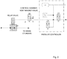
- FIG. 2 shows a schematic of the remote release valve 17 and associated pressure controller.
- the remote release valve has the following port connections: Port 1: pressure controller; Port 2: Relay valve control chamber; Port 3 connected to atmosphere.
- the valve arrangement provides or enables the following functionality: In the event of a loss of power supply to the brake control valve, the service brake should be released if applied and further reapplication prevented. This is achieved in normal running condition with power available as the solenoid valve 17 is energised connecting the control chamber to the VLCP pressure controller through the valve Port 2 to Port 1.
- the relay valve provides an output equal to the VLCP which the service brake controls.
- the solenoid 17 de-energises and drops out venting the control chamber pressure to atmosphere through the valve Port 2 to Port 3.
- the relay valve now vents the output pressure to zero; any brake cylinder pressure will now back feed through the service brake control membranes, as these will not retain pressure if the supply pressure is removed. Hence brake release is achieved and the supply pressure to the membranes in the hold valves is removed, preventing any subsequent service brake application.
- the FPGA will override the controlled emergency braking and apply a pneumatic only controlled load weighed emergency brake. This is achieved by disabling the service brake (i.e. opening the hold valves and closing the vent valves) and de-energising the control chamber vent magnet valve 17. This vents the control chamber pressure to atmosphere through magnet valve Port 2 to Port 3.
- This pressure can be set at an enhanced value of the load weighed level to enable emergency braking functionality.
- An exemplary value of the enhanced value is 125%.
- control chamber diaphragm effective area provides a 1:1 ratio between the control chamber and the output pressures. If the control chamber is not vented the output pressure to the brake cylinders would be 125% of the load weighed level required, i.e. 25% overbraked.
- the controlled emergency braking will become active, the emergency magnet valve, which when energised is closed, will drop out allowing pressure into the emergency back-up chamber.
- the pressure level is set by the emergency regulator.
- the emergency regulator is designed to provide an output pressure nominally equal to the variable load pressure VLCP and no lower than the tare back-up setting.
- the emergency back-up chamber diaphragm effective area provides a 0.8:1 ratio between the emergency back-up chamber and output pressures - the 0.8 being the inverse of the enhanced value of the load weigh level. However it has a 1:1 ratio with the control chamber. During controlled emergency brake the pressures in the control chamber and emergency back-up chamber are equal. Therefore there is no additive downward force to the diaphragm pile.
- the FPGA decides to override the controlled emergency brake and vents the VLCP pressure from the control chamber the balancing force is now removed on the underside of the emergency back-up chamber diaphragm.
- VLCP pressure is locked in when the control chamber vent solenoid is de-energised. This ensures the reference pressure for the emergency regulator, which maintains the emergency back-up chamber pressure, is at the 125% of the nominal load weighed level.
- a further mode of operation allows a vehicle with a faulty direct brake or power supply issues within the train to be moved by a rescue locomotive or recovery train.
- control chamber magnet valve When the control chamber magnet valve is de-energised the control chamber is vented.
- the relay valve will now vent the output pressure to zero; any brake cylinder pressure will now back feed through the service brake control membranes and brake release will be achieved.
- the first indirect brake pressure application will now switch the double check valve 18 closing the route to exhaust through the magnet valve (Port 2 to Port 3) and connecting the indirect brake input port to the control chamber.
- the emergency brake loop (EBL) 19 must be high in order to achieve brake release in this mode of operation. If the EBL drops low the output resulting in the brake cylinders will depend on which of the two chambers, control or emergency back-up provide the highest force.
Landscapes
- Engineering & Computer Science (AREA)
- Transportation (AREA)
- Mechanical Engineering (AREA)
- Physics & Mathematics (AREA)
- Fluid Mechanics (AREA)
- Braking Systems And Boosters (AREA)
- Regulating Braking Force (AREA)
Abstract
Description
- The present invention relates to a valve arrangement for a railway vehicle brake system and in particular to a vent valve arrangement for use in the remote release and emergency braking functions.
- In known systems such as that disclosed in
EP1588913 andGB2359599 - The system has been proven in the field but suffers from variations in brake-pad friction that may occur during the brake application and from any mechanical factors that may cause the brake actuation on any bogie to generate a brake force different to that calculated from the brake system specification. These mechanical effects can lead to both under braking and over braking of the train.
- The present invention seeks to provide a brake system that enables a more precise control of the brake pressures resulting in a lower likelihood of under or over braking, in particular, but not exclusively, during emergency braking.
- According to the invention there is provided a brake system in accordance with the features of
Claim 1. - Preferred aspects of the invention can be found in the sub-claims
- The concept advantageously provides the expected vehicle deceleration rate, for a given brake step independently from the variations in brake-pad friction that may occur during the brake application and from any mechanical factors that may cause the brake actuation on any bogie to generate a brake force different to that calculated from the brake system specification.
- An exemplary embodiment of the invention will now be described in great detail with reference to the drawings in which:
-
Fig. 1 shows a pneumatic schematic of the brake valve arrangement; -
Fig. 2 shows a schematic of theremote release valve 17 and associated pressure controller. - To allow deceleration control of the pneumatic brakes (both emergency and service brake), the available brake force must set at a level above that derived from the brake calculations, in order that it can be increased during a brake application to offset any reduction of the brake force caused by the brake system's mechanical components including the brake pads. Depending on the control algorithm, the reduction in brake force may be train wide or segment wide. Likewise the deceleration control may require reduction of the brake force and hence applied brake pressures to counteract any over-braking caused by the mechanics of the brake system.
-
Fig. 1 shows a pneumatic schematic of the brake valve arrangement comprising amanifold 1 which receives the mainbrake supply pressure 2 and provides the pneumatic connection tobrake cylinders connection 5 and thedistributor valve 7. The load weigh input in standard use is measured by one or two of the auxiliary transducers. - The pneumatic valve unit 8 houses the main relay regulator 9, which receives an inlet pressure from the
brake supply pressure 2. The outlet of the main relay regulator 9 is connected to therespective inlets control valves configuration module 14, described in greater detail below. - The main relay regulator 9 is piloted by pressures from the
emergency regulator 15, which provides the tare back-up setting level and thecrush regulator 16. The regulators limit the pilot pressure levels. The outputs of thedouble check valve 18 and emergency regulator pilot the main relay regulator 9. The tare back-up setting is the minimum pressure available in an emergency in the event that the variable load control pressure (VLCP) pressure is less than the tare setting. The crush regulator setting level is the maximum pressure available to the VLCP control valves. Theemergency regulator 15 is connected to themain supply pressure 2 and the pilot input of the main relay regulator 9 via the Emergencybrake loop solenoid 19. - The
crush regulator 16 receives a pneumatic input from the mainbrake supply pressure 2 and the outlet is connected to an inlet and vent valve arrangement, which control the actual pressure to aremote release valve 17 which is connected to the outlet of the pressure regulator 9. The crush regulator is therefore connected to the main relay regulator 9 via aremote release valve 17. The optional low weigh connection is provided with a path to the inlet of theremote release valve 17. Adouble check valve 18 is provided in the path between theremote release valve 17 and the regulator 9, which double check valve is also pneumatically connected to theindirect brake input 7. - The
control valves control valves respective control valves - As described above, the outlet of the main relay regulator 9 is connected to the
configuration module 14. Theconfiguration module 14 is provided with a respective choke in thepneumatic path respective choke configuration module 14. The vent membranes exhaust the brake cylinders via the configuration module. - In use, the brake application time and vent time are determined by the size of the choke holes which enable the standard or desired application and release times to be achieved irrespective of the brake cylinder volume. This ensures a predictable brake cylinder pressure control and wheel slide protection performance.
- In the invention, to provide the deceleration control function, regulation of the brake cylinder pressure (by the microcontroller) continues during an emergency application. However, the brake controller must ensure that the brake cylinder pressure applied during an emergency stop does not drop below a minimum level and that, in the case of power-loss during an emergency brake stop, the nominal emergency brake pressure the pressure determined from the brake calculations as providing the required emergency deceleration for the vehicle's current load is applied to the brake cylinders.
- Furthermore to ensure that the brake valve arrangement, which is ideally SIL3 for emergency braking, provides a minimum level of emergency brake force whilst the brake cylinder pressure is being regulated by the microcontroller, which will typically be SIL2, the brake cylinder pressure is independently monitored by electronics or an electronic logical device (FPGA) which will detect the condition where the brake cylinder pressure falls below a pre-configured percentage of the nominal emergency brake pressure.
- Likewise this monitoring system can also ensure that the applied brake pressure does not exceed a pre-defined upper limit and thereby provides over-braking protection. Protection against under-braking is only active during an emergency brake application; otherwise brake release and low brake steps would not be possible in service brake mode. Protection against over-braking is active in both emergency and service brake modes.
- In emergency brake mode, the brake cylinder monitoring electronics or logic device disables brake cylinder pressure regulation by the microcontroller (thus also disabling control by the head-end device) and applies the nominal emergency pressure level at the brake cylinders in a manner analogous to the standard known emergency brake application.
- In service brake operation, the brake cylinder monitoring electronics or logic device will operate to release the brake cylinder pressure (on detecting over-pressure). This is compatible with the release functionality described below
- As WSP remains operation during an emergency brake application provided the unit is powered), WSP operation can occur whilst controlled emergency brake is active. To control wheel-slide and optimise the available adhesion during an emergency brake stop, WSP control activity may cause the brake cylinder pressure to fall below the minimum pressure level defined for controlled emergency brake. Monitoring electronics may be provided to prevent an immediate cut out of functionality in the event of an underpressure being detected. As this pressure reduction is acceptable, control of the brake cylinder pressure by the WSP System will prevent the monitoring electronics/logic device from forcing the under-pressure trip. WSP activity used by the monitoring electronics/logic device is detected at the point of actuation of the valves, so that any modulation of the pressure (hold or vent) by the WSP control disables the under-pressure trip. The WSP operation is itself monitored by high integrity (SIL3) electronics (or electronic logic device) to prevent prolonged reduction of the brake cylinder pressure by the WSP control. Operation of these electronics will ensure that the valves cannot be continuously driven by the WSP operation to maintain a low pressure, thus ensuring that the monitoring electronics/logic device is not permanently prevented from acting on an under-pressure condition.
-
Figure 2 shows a schematic of theremote release valve 17 and associated pressure controller. The remote release valve has the following port connections: Port 1: pressure controller; Port 2: Relay valve control chamber;Port 3 connected to atmosphere. - When the
remote release valve 17 is de-energised:Port 2 connected toPort 3,Port 1 blocked; when it isenergised Port 1 is connected toPort 2 andPort 3 blocked. The pneumatic relay valve, equivalent to relay valve 9 inFigure 1 has control input to output ratio = 1:1 - The valve arrangement provides or enables the following functionality:
In the event of a loss of power supply to the brake control valve, the service brake should be released if applied and further reapplication prevented. This is achieved in normal running condition with power available as thesolenoid valve 17 is energised connecting the control chamber to the VLCP pressure controller through thevalve Port 2 toPort 1. The relay valve provides an output equal to the VLCP which the service brake controls. - In the event of a loss of power, the
solenoid 17 de-energises and drops out venting the control chamber pressure to atmosphere through thevalve Port 2 toPort 3. The relay valve now vents the output pressure to zero; any brake cylinder pressure will now back feed through the service brake control membranes, as these will not retain pressure if the supply pressure is removed. Hence brake release is achieved and the supply pressure to the membranes in the hold valves is removed, preventing any subsequent service brake application. - In the event of the controlled emergency braking exceeding the safety envelope the FPGA will override the controlled emergency braking and apply a pneumatic only controlled load weighed emergency brake. This is achieved by disabling the service brake (i.e. opening the hold valves and closing the vent valves) and de-energising the control chamber
vent magnet valve 17. This vents the control chamber pressure to atmosphere throughmagnet valve Port 2 toPort 3. This pressure can be set at an enhanced value of the load weighed level to enable emergency braking functionality. An exemplary value of the enhanced value is 125%. - The control chamber diaphragm effective area provides a 1:1 ratio between the control chamber and the output pressures. If the control chamber is not vented the output pressure to the brake cylinders would be 125% of the load weighed level required, i.e. 25% overbraked.
- At the initiation of the emergency brake application the controlled emergency braking will become active, the emergency magnet valve, which when energised is closed, will drop out allowing pressure into the emergency back-up chamber. The pressure level is set by the emergency regulator. The emergency regulator is designed to provide an output pressure nominally equal to the variable load pressure VLCP and no lower than the tare back-up setting.
- The emergency back-up chamber diaphragm effective area provides a 0.8:1 ratio between the emergency back-up chamber and output pressures - the 0.8 being the inverse of the enhanced value of the load weigh level. However it has a 1:1 ratio with the control chamber. During controlled emergency brake the pressures in the control chamber and emergency back-up chamber are equal. Therefore there is no additive downward force to the diaphragm pile.
- If the FPGA decides to override the controlled emergency brake and vents the VLCP pressure from the control chamber the balancing force is now removed on the underside of the emergency back-up chamber diaphragm.
- The VLCP pressure is locked in when the control chamber vent solenoid is de-energised. This ensures the reference pressure for the emergency regulator, which maintains the emergency back-up chamber pressure, is at the 125% of the nominal load weighed level.
- With the control chamber pressure vented, the force exerted from the emergency chamber diaphragm is now active through the diaphragm pile. This force is balanced by the brake cylinder pressure acting on the underside of the control diaphragm. As the emergency back-up chamber diaphragm to brake cylinder diaphragm ratio is 0.8:1.0, this corrects the output pressure in the brake cylinders to the nominal load weighed value, i.e. 1.25 x 0.8 = 1
- If a fault is detected within the brake control valve such as a 'dragging brake', release of the service brake is enabled, if applied, and further reapplication prevented. This functionality is achieved by an external digital input direct to the FPGA. When the FPGA receives this signal it inhibits the drive to the
solenoid 17 which de-energises. - When the
solenoid 17 is de-energised the control chamber is vented. The relay valve will now vent the output pressure to zero; any brake cylinder pressure will now back feed through the service brake control membranes, as they cannot retain pressure if the supply pressure is removed. Hence brake release is achieved and the supply pressure to the membranes is removed, preventing any subsequent service brake application. - A further mode of operation allows a vehicle with a faulty direct brake or power supply issues within the train to be moved by a rescue locomotive or recovery train.
- When the control chamber magnet valve is de-energised the control chamber is vented. The relay valve will now vent the output pressure to zero; any brake cylinder pressure will now back feed through the service brake control membranes and brake release will be achieved.
- The first indirect brake pressure application will now switch the
double check valve 18 closing the route to exhaust through the magnet valve (Port 2 to Port 3) and connecting the indirect brake input port to the control chamber. - The emergency brake loop (EBL) 19 must be high in order to achieve brake release in this mode of operation. If the EBL drops low the output resulting in the brake cylinders will depend on which of the two chambers, control or emergency back-up provide the highest force.
Claims (6)
- An electropneumatic rail brake system configured to provide emergency braking, having brake cylinders for applying a brake force, the brake system comprising an emergency magnet valve which controls air flow into an emergency regulator valve, which valve has an emergency back-up chamber, the emergency regulator being adapted to provide an output pressure nominally equal to the variable load pressure and no lower than a tare back-up setting and wherein the magnet valve is controlled by a first electronic control unit and closed when energised, characterised in that when the magnet valve is de-energised, pressure is allowed into the emergency back-up chamber, wherein regulation of the brake cylinder pressure by the electronic control unit continues during an emergency application such that the brake cylinder pressure applied during an emergency stop does not drop below a predetermined level and that, in the event of power-loss during an emergency brake stop, the nominal emergency brake pressure is applied to the brake cylinders.
- An electropneumatic rail brake system according to Claim 1, wherein the system comprises a second electronic control unit to provide a predetermined level of emergency brake force whilst the brake cylinder pressure is being regulated by the first electronic control unit, the brake cylinder pressure being independently monitored the second electronic control unit which is adapted to detect when the brake cylinder pressure falls below a predetermined amount or percentage of the nominal emergency brake pressure.
- An electropneumatic rail brake system according to Claim 2, wherein the second electronic control unit is adapted to ensure that the applied brake pressure does not exceed a pre-defined upper limit.
- An electropneumatic rail brake system according to any one of Claims 1 to 3, wherein protection against under-braking is only active during an emergency brake application.
- An electropneumatic rail brake system according to any one of Claims 1 to 4, wherein protection against over-braking is active in both emergency and service brake modes.
- An electropneumatic rail brake system according to any one of Claims 2 to 5, wherein during emergency braking, the second electronic control unit disables brake cylinder pressure regulation by the first electronic control unit and applies the nominal emergency pressure level to the brake cylinders.
Priority Applications (8)
| Application Number | Priority Date | Filing Date | Title |
|---|---|---|---|
| ES18193590T ES2966682T3 (en) | 2018-09-11 | 2018-09-11 | Brake system |
| PL18193590.9T PL3623236T3 (en) | 2018-09-11 | 2018-09-11 | Brake system |
| EP18193590.9A EP3623236B1 (en) | 2018-09-11 | 2018-09-11 | Brake system |
| US17/275,652 US12065120B2 (en) | 2018-09-11 | 2019-09-10 | Brake control valve arrangement |
| PCT/EP2019/074271 WO2020053302A1 (en) | 2018-09-11 | 2019-09-11 | Brake control valve arrangement |
| KR1020217010471A KR102530202B1 (en) | 2018-09-11 | 2019-09-11 | brake control valve device |
| JP2021513425A JP7230181B2 (en) | 2018-09-11 | 2019-09-11 | brake control valve device |
| CN201980059336.6A CN112703137B (en) | 2018-09-11 | 2019-09-11 | Brake control valve device |
Applications Claiming Priority (1)
| Application Number | Priority Date | Filing Date | Title |
|---|---|---|---|
| EP18193590.9A EP3623236B1 (en) | 2018-09-11 | 2018-09-11 | Brake system |
Publications (2)
| Publication Number | Publication Date |
|---|---|
| EP3623236A1 true EP3623236A1 (en) | 2020-03-18 |
| EP3623236B1 EP3623236B1 (en) | 2023-11-08 |
Family
ID=63557260
Family Applications (1)
| Application Number | Title | Priority Date | Filing Date |
|---|---|---|---|
| EP18193590.9A Active EP3623236B1 (en) | 2018-09-11 | 2018-09-11 | Brake system |
Country Status (8)
| Country | Link |
|---|---|
| US (1) | US12065120B2 (en) |
| EP (1) | EP3623236B1 (en) |
| JP (1) | JP7230181B2 (en) |
| KR (1) | KR102530202B1 (en) |
| CN (1) | CN112703137B (en) |
| ES (1) | ES2966682T3 (en) |
| PL (1) | PL3623236T3 (en) |
| WO (1) | WO2020053302A1 (en) |
Families Citing this family (2)
| Publication number | Priority date | Publication date | Assignee | Title |
|---|---|---|---|---|
| ES2966682T3 (en) * | 2018-09-11 | 2024-04-23 | Knorr Bremse Systeme | Brake system |
| CN116749930A (en) * | 2023-05-16 | 2023-09-15 | 羿鹏轨道交通开发(上海)有限公司 | A mechanical braking system for a suspended monorail vehicle and its control method |
Citations (5)
| Publication number | Priority date | Publication date | Assignee | Title |
|---|---|---|---|---|
| GB2359599A (en) | 2000-02-25 | 2001-08-29 | Westinghouse Brake & Signal | Controlling the application of air pressure to brake actuators e.g.for railway vehicles |
| EP1588913A1 (en) | 2004-04-20 | 2005-10-26 | SAB WABCO S.p.A. | An electro-pneumatic braking control unit for a railway or tramway vehicle |
| WO2011086029A2 (en) * | 2010-01-18 | 2011-07-21 | Siemens Aktiengesellschaft | Brake arrangement of a railway vehicle |
| WO2013144543A2 (en) * | 2012-03-26 | 2013-10-03 | Knorr-Bremse Rail Systems (Uk) Limited | Emergency braking |
| WO2015181764A1 (en) * | 2014-05-28 | 2015-12-03 | Faiveley Transport Italia S.P.A. | Electro-pneumatic braking system for a railway vehicle |
Family Cites Families (8)
| Publication number | Priority date | Publication date | Assignee | Title |
|---|---|---|---|---|
| GB2359600A (en) * | 2000-02-25 | 2001-08-29 | Westinghouse Brake & Signal | Controlling a pneumatic brake system |
| US7520574B2 (en) * | 2006-03-28 | 2009-04-21 | Wabtec Holding Corporation | Pneumatic emergency brake release timer |
| JP5354097B2 (en) | 2011-05-13 | 2013-11-27 | 株式会社村田製作所 | Power transmission device, power reception device, and power transmission system |
| ITUB20152413A1 (en) | 2015-07-22 | 2017-01-22 | Faiveley Transport Italia Spa | Pneumatic braking system for a railway vehicle, with brake release solenoid valve. |
| DE102018200487A1 (en) * | 2018-01-12 | 2019-07-18 | Knorr-Bremse Systeme für Schienenfahrzeuge GmbH | Apparatus and method for realizing controlled reactions in case of system failure |
| ES2892284T3 (en) * | 2018-09-11 | 2022-02-03 | Knorr Bremse Systeme | configuration module |
| ES2966682T3 (en) * | 2018-09-11 | 2024-04-23 | Knorr Bremse Systeme | Brake system |
| CN113104058B (en) * | 2021-05-28 | 2023-01-06 | 中车青岛四方车辆研究所有限公司 | Air brake control unit, brake control device and method for railway vehicle |
-
2018
- 2018-09-11 ES ES18193590T patent/ES2966682T3/en active Active
- 2018-09-11 EP EP18193590.9A patent/EP3623236B1/en active Active
- 2018-09-11 PL PL18193590.9T patent/PL3623236T3/en unknown
-
2019
- 2019-09-10 US US17/275,652 patent/US12065120B2/en active Active
- 2019-09-11 CN CN201980059336.6A patent/CN112703137B/en active Active
- 2019-09-11 WO PCT/EP2019/074271 patent/WO2020053302A1/en not_active Ceased
- 2019-09-11 KR KR1020217010471A patent/KR102530202B1/en active Active
- 2019-09-11 JP JP2021513425A patent/JP7230181B2/en active Active
Patent Citations (5)
| Publication number | Priority date | Publication date | Assignee | Title |
|---|---|---|---|---|
| GB2359599A (en) | 2000-02-25 | 2001-08-29 | Westinghouse Brake & Signal | Controlling the application of air pressure to brake actuators e.g.for railway vehicles |
| EP1588913A1 (en) | 2004-04-20 | 2005-10-26 | SAB WABCO S.p.A. | An electro-pneumatic braking control unit for a railway or tramway vehicle |
| WO2011086029A2 (en) * | 2010-01-18 | 2011-07-21 | Siemens Aktiengesellschaft | Brake arrangement of a railway vehicle |
| WO2013144543A2 (en) * | 2012-03-26 | 2013-10-03 | Knorr-Bremse Rail Systems (Uk) Limited | Emergency braking |
| WO2015181764A1 (en) * | 2014-05-28 | 2015-12-03 | Faiveley Transport Italia S.P.A. | Electro-pneumatic braking system for a railway vehicle |
Also Published As
| Publication number | Publication date |
|---|---|
| ES2966682T3 (en) | 2024-04-23 |
| KR102530202B1 (en) | 2023-05-08 |
| CN112703137B (en) | 2023-06-20 |
| WO2020053302A1 (en) | 2020-03-19 |
| US12065120B2 (en) | 2024-08-20 |
| JP2021536400A (en) | 2021-12-27 |
| CN112703137A (en) | 2021-04-23 |
| EP3623236B1 (en) | 2023-11-08 |
| PL3623236T3 (en) | 2024-04-15 |
| KR20210049926A (en) | 2021-05-06 |
| JP7230181B2 (en) | 2023-02-28 |
| US20220041147A1 (en) | 2022-02-10 |
Similar Documents
| Publication | Publication Date | Title |
|---|---|---|
| US12084032B2 (en) | Brake control valve arrangement | |
| US8708430B2 (en) | Pneumatic vehicle brake system and control method | |
| US4598953A (en) | Electropneumatic brake control system for railway transit vehicle | |
| US9545907B2 (en) | Control valve device for a rail vehicle brake | |
| GB2502252A (en) | Emergency braking for a railway vehicle | |
| US5662391A (en) | Pneumatic empty/load proportioning for electro-pneumatic brake | |
| US7661770B2 (en) | Pneumatic emergency brake assurance module | |
| MXPA02004457A (en) | Four port variable load valve weigh system for a brake pipe controlled brake system. | |
| JP7034303B2 (en) | Equipment and methods for achieving controlled response in the event of a system failure | |
| US12065120B2 (en) | Brake control valve arrangement | |
| CN107438544B (en) | Compressed air unit for vehicles with double relay valve | |
| US3716274A (en) | Combined electronic and fluid pressure brake control apparatus | |
| US3890013A (en) | Electrically controlled fluid pressure system for converting digital control signals to analog signals | |
| US3709564A (en) | Combined electronic and fluid pressure brake apparatus | |
| US11548491B2 (en) | Electronically controlled pneumatic (ECP) overlay control valve | |
| US11834017B2 (en) | Device and method for realizing controlled reactions in the event of a system malfunction |
Legal Events
| Date | Code | Title | Description |
|---|---|---|---|
| PUAI | Public reference made under article 153(3) epc to a published international application that has entered the european phase |
Free format text: ORIGINAL CODE: 0009012 |
|
| STAA | Information on the status of an ep patent application or granted ep patent |
Free format text: STATUS: THE APPLICATION HAS BEEN PUBLISHED |
|
| AK | Designated contracting states |
Kind code of ref document: A1 Designated state(s): AL AT BE BG CH CY CZ DE DK EE ES FI FR GB GR HR HU IE IS IT LI LT LU LV MC MK MT NL NO PL PT RO RS SE SI SK SM TR |
|
| AX | Request for extension of the european patent |
Extension state: BA ME |
|
| STAA | Information on the status of an ep patent application or granted ep patent |
Free format text: STATUS: REQUEST FOR EXAMINATION WAS MADE |
|
| 17P | Request for examination filed |
Effective date: 20200918 |
|
| RBV | Designated contracting states (corrected) |
Designated state(s): AL AT BE BG CH CY CZ DE DK EE ES FI FR GB GR HR HU IE IS IT LI LT LU LV MC MK MT NL NO PL PT RO RS SE SI SK SM TR |
|
| STAA | Information on the status of an ep patent application or granted ep patent |
Free format text: STATUS: EXAMINATION IS IN PROGRESS |
|
| 17Q | First examination report despatched |
Effective date: 20220906 |
|
| GRAP | Despatch of communication of intention to grant a patent |
Free format text: ORIGINAL CODE: EPIDOSNIGR1 |
|
| STAA | Information on the status of an ep patent application or granted ep patent |
Free format text: STATUS: GRANT OF PATENT IS INTENDED |
|
| INTG | Intention to grant announced |
Effective date: 20230503 |
|
| GRAS | Grant fee paid |
Free format text: ORIGINAL CODE: EPIDOSNIGR3 |
|
| GRAA | (expected) grant |
Free format text: ORIGINAL CODE: 0009210 |
|
| STAA | Information on the status of an ep patent application or granted ep patent |
Free format text: STATUS: THE PATENT HAS BEEN GRANTED |
|
| AK | Designated contracting states |
Kind code of ref document: B1 Designated state(s): AL AT BE BG CH CY CZ DE DK EE ES FI FR GB GR HR HU IE IS IT LI LT LU LV MC MK MT NL NO PL PT RO RS SE SI SK SM TR |
|
| REG | Reference to a national code |
Ref country code: GB Ref legal event code: FG4D |
|
| REG | Reference to a national code |
Ref country code: CH Ref legal event code: EP |
|
| REG | Reference to a national code |
Ref country code: DE Ref legal event code: R096 Ref document number: 602018060725 Country of ref document: DE |
|
| REG | Reference to a national code |
Ref country code: IE Ref legal event code: FG4D |
|
| REG | Reference to a national code |
Ref country code: SE Ref legal event code: TRGR |
|
| P01 | Opt-out of the competence of the unified patent court (upc) registered |
Effective date: 20231220 |
|
| REG | Reference to a national code |
Ref country code: LT Ref legal event code: MG9D |
|
| REG | Reference to a national code |
Ref country code: NL Ref legal event code: MP Effective date: 20231108 |
|
| PG25 | Lapsed in a contracting state [announced via postgrant information from national office to epo] |
Ref country code: GR Free format text: LAPSE BECAUSE OF FAILURE TO SUBMIT A TRANSLATION OF THE DESCRIPTION OR TO PAY THE FEE WITHIN THE PRESCRIBED TIME-LIMIT Effective date: 20240209 |
|
| PG25 | Lapsed in a contracting state [announced via postgrant information from national office to epo] |
Ref country code: IS Free format text: LAPSE BECAUSE OF FAILURE TO SUBMIT A TRANSLATION OF THE DESCRIPTION OR TO PAY THE FEE WITHIN THE PRESCRIBED TIME-LIMIT Effective date: 20240308 |
|
| PG25 | Lapsed in a contracting state [announced via postgrant information from national office to epo] |
Ref country code: LT Free format text: LAPSE BECAUSE OF FAILURE TO SUBMIT A TRANSLATION OF THE DESCRIPTION OR TO PAY THE FEE WITHIN THE PRESCRIBED TIME-LIMIT Effective date: 20231108 |
|
| REG | Reference to a national code |
Ref country code: AT Ref legal event code: MK05 Ref document number: 1629359 Country of ref document: AT Kind code of ref document: T Effective date: 20231108 |
|
| PG25 | Lapsed in a contracting state [announced via postgrant information from national office to epo] |
Ref country code: NL Free format text: LAPSE BECAUSE OF FAILURE TO SUBMIT A TRANSLATION OF THE DESCRIPTION OR TO PAY THE FEE WITHIN THE PRESCRIBED TIME-LIMIT Effective date: 20231108 |
|
| PG25 | Lapsed in a contracting state [announced via postgrant information from national office to epo] |
Ref country code: AT Free format text: LAPSE BECAUSE OF FAILURE TO SUBMIT A TRANSLATION OF THE DESCRIPTION OR TO PAY THE FEE WITHIN THE PRESCRIBED TIME-LIMIT Effective date: 20231108 |
|
| REG | Reference to a national code |
Ref country code: ES Ref legal event code: FG2A Ref document number: 2966682 Country of ref document: ES Kind code of ref document: T3 Effective date: 20240423 |
|
| PG25 | Lapsed in a contracting state [announced via postgrant information from national office to epo] |
Ref country code: NL Free format text: LAPSE BECAUSE OF FAILURE TO SUBMIT A TRANSLATION OF THE DESCRIPTION OR TO PAY THE FEE WITHIN THE PRESCRIBED TIME-LIMIT Effective date: 20231108 Ref country code: LT Free format text: LAPSE BECAUSE OF FAILURE TO SUBMIT A TRANSLATION OF THE DESCRIPTION OR TO PAY THE FEE WITHIN THE PRESCRIBED TIME-LIMIT Effective date: 20231108 Ref country code: IS Free format text: LAPSE BECAUSE OF FAILURE TO SUBMIT A TRANSLATION OF THE DESCRIPTION OR TO PAY THE FEE WITHIN THE PRESCRIBED TIME-LIMIT Effective date: 20240308 Ref country code: GR Free format text: LAPSE BECAUSE OF FAILURE TO SUBMIT A TRANSLATION OF THE DESCRIPTION OR TO PAY THE FEE WITHIN THE PRESCRIBED TIME-LIMIT Effective date: 20240209 Ref country code: BG Free format text: LAPSE BECAUSE OF FAILURE TO SUBMIT A TRANSLATION OF THE DESCRIPTION OR TO PAY THE FEE WITHIN THE PRESCRIBED TIME-LIMIT Effective date: 20240208 Ref country code: AT Free format text: LAPSE BECAUSE OF FAILURE TO SUBMIT A TRANSLATION OF THE DESCRIPTION OR TO PAY THE FEE WITHIN THE PRESCRIBED TIME-LIMIT Effective date: 20231108 Ref country code: PT Free format text: LAPSE BECAUSE OF FAILURE TO SUBMIT A TRANSLATION OF THE DESCRIPTION OR TO PAY THE FEE WITHIN THE PRESCRIBED TIME-LIMIT Effective date: 20240308 |
|
| PG25 | Lapsed in a contracting state [announced via postgrant information from national office to epo] |
Ref country code: RS Free format text: LAPSE BECAUSE OF FAILURE TO SUBMIT A TRANSLATION OF THE DESCRIPTION OR TO PAY THE FEE WITHIN THE PRESCRIBED TIME-LIMIT Effective date: 20231108 Ref country code: NO Free format text: LAPSE BECAUSE OF FAILURE TO SUBMIT A TRANSLATION OF THE DESCRIPTION OR TO PAY THE FEE WITHIN THE PRESCRIBED TIME-LIMIT Effective date: 20240208 Ref country code: LV Free format text: LAPSE BECAUSE OF FAILURE TO SUBMIT A TRANSLATION OF THE DESCRIPTION OR TO PAY THE FEE WITHIN THE PRESCRIBED TIME-LIMIT Effective date: 20231108 Ref country code: HR Free format text: LAPSE BECAUSE OF FAILURE TO SUBMIT A TRANSLATION OF THE DESCRIPTION OR TO PAY THE FEE WITHIN THE PRESCRIBED TIME-LIMIT Effective date: 20231108 |
|
| PG25 | Lapsed in a contracting state [announced via postgrant information from national office to epo] |
Ref country code: DK Free format text: LAPSE BECAUSE OF FAILURE TO SUBMIT A TRANSLATION OF THE DESCRIPTION OR TO PAY THE FEE WITHIN THE PRESCRIBED TIME-LIMIT Effective date: 20231108 |
|
| PG25 | Lapsed in a contracting state [announced via postgrant information from national office to epo] |
Ref country code: CZ Free format text: LAPSE BECAUSE OF FAILURE TO SUBMIT A TRANSLATION OF THE DESCRIPTION OR TO PAY THE FEE WITHIN THE PRESCRIBED TIME-LIMIT Effective date: 20231108 |
|
| PG25 | Lapsed in a contracting state [announced via postgrant information from national office to epo] |
Ref country code: SK Free format text: LAPSE BECAUSE OF FAILURE TO SUBMIT A TRANSLATION OF THE DESCRIPTION OR TO PAY THE FEE WITHIN THE PRESCRIBED TIME-LIMIT Effective date: 20231108 |
|
| PG25 | Lapsed in a contracting state [announced via postgrant information from national office to epo] |
Ref country code: SM Free format text: LAPSE BECAUSE OF FAILURE TO SUBMIT A TRANSLATION OF THE DESCRIPTION OR TO PAY THE FEE WITHIN THE PRESCRIBED TIME-LIMIT Effective date: 20231108 Ref country code: SK Free format text: LAPSE BECAUSE OF FAILURE TO SUBMIT A TRANSLATION OF THE DESCRIPTION OR TO PAY THE FEE WITHIN THE PRESCRIBED TIME-LIMIT Effective date: 20231108 Ref country code: RO Free format text: LAPSE BECAUSE OF FAILURE TO SUBMIT A TRANSLATION OF THE DESCRIPTION OR TO PAY THE FEE WITHIN THE PRESCRIBED TIME-LIMIT Effective date: 20231108 Ref country code: EE Free format text: LAPSE BECAUSE OF FAILURE TO SUBMIT A TRANSLATION OF THE DESCRIPTION OR TO PAY THE FEE WITHIN THE PRESCRIBED TIME-LIMIT Effective date: 20231108 Ref country code: DK Free format text: LAPSE BECAUSE OF FAILURE TO SUBMIT A TRANSLATION OF THE DESCRIPTION OR TO PAY THE FEE WITHIN THE PRESCRIBED TIME-LIMIT Effective date: 20231108 Ref country code: CZ Free format text: LAPSE BECAUSE OF FAILURE TO SUBMIT A TRANSLATION OF THE DESCRIPTION OR TO PAY THE FEE WITHIN THE PRESCRIBED TIME-LIMIT Effective date: 20231108 |
|
| REG | Reference to a national code |
Ref country code: DE Ref legal event code: R097 Ref document number: 602018060725 Country of ref document: DE |
|
| PLBE | No opposition filed within time limit |
Free format text: ORIGINAL CODE: 0009261 |
|
| STAA | Information on the status of an ep patent application or granted ep patent |
Free format text: STATUS: NO OPPOSITION FILED WITHIN TIME LIMIT |
|
| 26N | No opposition filed |
Effective date: 20240809 |
|
| PG25 | Lapsed in a contracting state [announced via postgrant information from national office to epo] |
Ref country code: SI Free format text: LAPSE BECAUSE OF FAILURE TO SUBMIT A TRANSLATION OF THE DESCRIPTION OR TO PAY THE FEE WITHIN THE PRESCRIBED TIME-LIMIT Effective date: 20231108 |
|
| PG25 | Lapsed in a contracting state [announced via postgrant information from national office to epo] |
Ref country code: SI Free format text: LAPSE BECAUSE OF FAILURE TO SUBMIT A TRANSLATION OF THE DESCRIPTION OR TO PAY THE FEE WITHIN THE PRESCRIBED TIME-LIMIT Effective date: 20231108 |
|
| PG25 | Lapsed in a contracting state [announced via postgrant information from national office to epo] |
Ref country code: MC Free format text: LAPSE BECAUSE OF FAILURE TO SUBMIT A TRANSLATION OF THE DESCRIPTION OR TO PAY THE FEE WITHIN THE PRESCRIBED TIME-LIMIT Effective date: 20231108 |
|
| PG25 | Lapsed in a contracting state [announced via postgrant information from national office to epo] |
Ref country code: LU Free format text: LAPSE BECAUSE OF NON-PAYMENT OF DUE FEES Effective date: 20240911 |
|
| REG | Reference to a national code |
Ref country code: BE Ref legal event code: MM Effective date: 20240930 |
|
| PG25 | Lapsed in a contracting state [announced via postgrant information from national office to epo] |
Ref country code: BE Free format text: LAPSE BECAUSE OF NON-PAYMENT OF DUE FEES Effective date: 20240930 |
|
| PG25 | Lapsed in a contracting state [announced via postgrant information from national office to epo] |
Ref country code: IE Free format text: LAPSE BECAUSE OF NON-PAYMENT OF DUE FEES Effective date: 20240911 |
|
| REG | Reference to a national code |
Ref country code: CH Ref legal event code: U11 Free format text: ST27 STATUS EVENT CODE: U-0-0-U10-U11 (AS PROVIDED BY THE NATIONAL OFFICE) Effective date: 20251001 |
|
| PG25 | Lapsed in a contracting state [announced via postgrant information from national office to epo] |
Ref country code: FI Free format text: LAPSE BECAUSE OF FAILURE TO SUBMIT A TRANSLATION OF THE DESCRIPTION OR TO PAY THE FEE WITHIN THE PRESCRIBED TIME-LIMIT Effective date: 20231108 |
|
| PGFP | Annual fee paid to national office [announced via postgrant information from national office to epo] |
Ref country code: DE Payment date: 20250926 Year of fee payment: 8 |
|
| PGFP | Annual fee paid to national office [announced via postgrant information from national office to epo] |
Ref country code: PL Payment date: 20250818 Year of fee payment: 8 Ref country code: IT Payment date: 20250919 Year of fee payment: 8 |
|
| PGFP | Annual fee paid to national office [announced via postgrant information from national office to epo] |
Ref country code: GB Payment date: 20250923 Year of fee payment: 8 |
|
| PGFP | Annual fee paid to national office [announced via postgrant information from national office to epo] |
Ref country code: FR Payment date: 20250924 Year of fee payment: 8 |
|
| PGFP | Annual fee paid to national office [announced via postgrant information from national office to epo] |
Ref country code: SE Payment date: 20250924 Year of fee payment: 8 |
|
| PGFP | Annual fee paid to national office [announced via postgrant information from national office to epo] |
Ref country code: CH Payment date: 20251001 Year of fee payment: 8 |
|
| PG25 | Lapsed in a contracting state [announced via postgrant information from national office to epo] |
Ref country code: CY Free format text: LAPSE BECAUSE OF FAILURE TO SUBMIT A TRANSLATION OF THE DESCRIPTION OR TO PAY THE FEE WITHIN THE PRESCRIBED TIME-LIMIT; INVALID AB INITIO Effective date: 20180911 |
|
| PGFP | Annual fee paid to national office [announced via postgrant information from national office to epo] |
Ref country code: ES Payment date: 20251010 Year of fee payment: 8 |
|
| PG25 | Lapsed in a contracting state [announced via postgrant information from national office to epo] |
Ref country code: HU Free format text: LAPSE BECAUSE OF FAILURE TO SUBMIT A TRANSLATION OF THE DESCRIPTION OR TO PAY THE FEE WITHIN THE PRESCRIBED TIME-LIMIT; INVALID AB INITIO Effective date: 20180911 |