EP3623233A1 - Vehicle and control method thereof - Google Patents
Vehicle and control method thereof Download PDFInfo
- Publication number
- EP3623233A1 EP3623233A1 EP18210987.6A EP18210987A EP3623233A1 EP 3623233 A1 EP3623233 A1 EP 3623233A1 EP 18210987 A EP18210987 A EP 18210987A EP 3623233 A1 EP3623233 A1 EP 3623233A1
- Authority
- EP
- European Patent Office
- Prior art keywords
- vehicle
- radio signal
- capacitor
- signal
- antenna
- Prior art date
- Legal status (The legal status is an assumption and is not a legal conclusion. Google has not performed a legal analysis and makes no representation as to the accuracy of the status listed.)
- Granted
Links
Images


Classifications
-
- B—PERFORMING OPERATIONS; TRANSPORTING
- B60—VEHICLES IN GENERAL
- B60R—VEHICLES, VEHICLE FITTINGS, OR VEHICLE PARTS, NOT OTHERWISE PROVIDED FOR
- B60R25/00—Fittings or systems for preventing or indicating unauthorised use or theft of vehicles
- B60R25/20—Means to switch the anti-theft system on or off
- B60R25/24—Means to switch the anti-theft system on or off using electronic identifiers containing a code not memorised by the user
- B60R25/245—Means to switch the anti-theft system on or off using electronic identifiers containing a code not memorised by the user where the antenna reception area plays a role
-
- B—PERFORMING OPERATIONS; TRANSPORTING
- B60—VEHICLES IN GENERAL
- B60R—VEHICLES, VEHICLE FITTINGS, OR VEHICLE PARTS, NOT OTHERWISE PROVIDED FOR
- B60R25/00—Fittings or systems for preventing or indicating unauthorised use or theft of vehicles
- B60R25/20—Means to switch the anti-theft system on or off
- B60R25/24—Means to switch the anti-theft system on or off using electronic identifiers containing a code not memorised by the user
-
- B—PERFORMING OPERATIONS; TRANSPORTING
- B60—VEHICLES IN GENERAL
- B60R—VEHICLES, VEHICLE FITTINGS, OR VEHICLE PARTS, NOT OTHERWISE PROVIDED FOR
- B60R25/00—Fittings or systems for preventing or indicating unauthorised use or theft of vehicles
- B60R25/10—Fittings or systems for preventing or indicating unauthorised use or theft of vehicles actuating a signalling device
- B60R25/102—Fittings or systems for preventing or indicating unauthorised use or theft of vehicles actuating a signalling device a signal being sent to a remote location, e.g. a radio signal being transmitted to a police station, a security company or the owner
-
- G—PHYSICS
- G07—CHECKING-DEVICES
- G07C—TIME OR ATTENDANCE REGISTERS; REGISTERING OR INDICATING THE WORKING OF MACHINES; GENERATING RANDOM NUMBERS; VOTING OR LOTTERY APPARATUS; ARRANGEMENTS, SYSTEMS OR APPARATUS FOR CHECKING NOT PROVIDED FOR ELSEWHERE
- G07C9/00—Individual registration on entry or exit
- G07C9/00174—Electronically operated locks; Circuits therefor; Nonmechanical keys therefor, e.g. passive or active electrical keys or other data carriers without mechanical keys
- G07C9/00309—Electronically operated locks; Circuits therefor; Nonmechanical keys therefor, e.g. passive or active electrical keys or other data carriers without mechanical keys operated with bidirectional data transmission between data carrier and locks
-
- H—ELECTRICITY
- H01—ELECTRIC ELEMENTS
- H01Q—ANTENNAS, i.e. RADIO AERIALS
- H01Q1/00—Details of, or arrangements associated with, antennas
- H01Q1/27—Adaptation for use in or on movable bodies
- H01Q1/32—Adaptation for use in or on road or rail vehicles
- H01Q1/3208—Adaptation for use in or on road or rail vehicles characterised by the application wherein the antenna is used
- H01Q1/3233—Adaptation for use in or on road or rail vehicles characterised by the application wherein the antenna is used particular used as part of a sensor or in a security system, e.g. for automotive radar, navigation systems
- H01Q1/3241—Adaptation for use in or on road or rail vehicles characterised by the application wherein the antenna is used particular used as part of a sensor or in a security system, e.g. for automotive radar, navigation systems particular used in keyless entry systems
-
- H—ELECTRICITY
- H04—ELECTRIC COMMUNICATION TECHNIQUE
- H04L—TRANSMISSION OF DIGITAL INFORMATION, e.g. TELEGRAPHIC COMMUNICATION
- H04L9/00—Cryptographic mechanisms or cryptographic arrangements for secret or secure communications; Network security protocols
- H04L9/08—Key distribution or management, e.g. generation, sharing or updating, of cryptographic keys or passwords
- H04L9/0861—Generation of secret information including derivation or calculation of cryptographic keys or passwords
- H04L9/0863—Generation of secret information including derivation or calculation of cryptographic keys or passwords involving passwords or one-time passwords
-
- H—ELECTRICITY
- H04—ELECTRIC COMMUNICATION TECHNIQUE
- H04L—TRANSMISSION OF DIGITAL INFORMATION, e.g. TELEGRAPHIC COMMUNICATION
- H04L9/00—Cryptographic mechanisms or cryptographic arrangements for secret or secure communications; Network security protocols
- H04L9/08—Key distribution or management, e.g. generation, sharing or updating, of cryptographic keys or passwords
- H04L9/0861—Generation of secret information including derivation or calculation of cryptographic keys or passwords
- H04L9/0872—Generation of secret information including derivation or calculation of cryptographic keys or passwords using geo-location information, e.g. location data, time, relative position or proximity to other entities
-
- G—PHYSICS
- G07—CHECKING-DEVICES
- G07C—TIME OR ATTENDANCE REGISTERS; REGISTERING OR INDICATING THE WORKING OF MACHINES; GENERATING RANDOM NUMBERS; VOTING OR LOTTERY APPARATUS; ARRANGEMENTS, SYSTEMS OR APPARATUS FOR CHECKING NOT PROVIDED FOR ELSEWHERE
- G07C9/00—Individual registration on entry or exit
- G07C9/00174—Electronically operated locks; Circuits therefor; Nonmechanical keys therefor, e.g. passive or active electrical keys or other data carriers without mechanical keys
- G07C9/00309—Electronically operated locks; Circuits therefor; Nonmechanical keys therefor, e.g. passive or active electrical keys or other data carriers without mechanical keys operated with bidirectional data transmission between data carrier and locks
- G07C2009/0042—Electronically operated locks; Circuits therefor; Nonmechanical keys therefor, e.g. passive or active electrical keys or other data carriers without mechanical keys operated with bidirectional data transmission between data carrier and locks the transmitted data signal containing a code which is changed
- G07C2009/00428—Electronically operated locks; Circuits therefor; Nonmechanical keys therefor, e.g. passive or active electrical keys or other data carriers without mechanical keys operated with bidirectional data transmission between data carrier and locks the transmitted data signal containing a code which is changed periodically after a time period
- G07C2009/00468—Electronically operated locks; Circuits therefor; Nonmechanical keys therefor, e.g. passive or active electrical keys or other data carriers without mechanical keys operated with bidirectional data transmission between data carrier and locks the transmitted data signal containing a code which is changed periodically after a time period after n uses
-
- G—PHYSICS
- G07—CHECKING-DEVICES
- G07C—TIME OR ATTENDANCE REGISTERS; REGISTERING OR INDICATING THE WORKING OF MACHINES; GENERATING RANDOM NUMBERS; VOTING OR LOTTERY APPARATUS; ARRANGEMENTS, SYSTEMS OR APPARATUS FOR CHECKING NOT PROVIDED FOR ELSEWHERE
- G07C2209/00—Indexing scheme relating to groups G07C9/00 - G07C9/38
- G07C2209/08—With time considerations, e.g. temporary activation, valid time window or time limitations
Definitions
- the present disclosure relates to a vehicle, a control method thereof, and a transceiver for the vehicle, and more particularly, to a vehicle, a control method thereof, and a transceiver for the vehicle capable of enhancing security.
- a user identification device e.g., a smart key
- the vehicle can authenticate the driver using the UID, and can restrict vehicle control (e.g., acceleration control, steering control, braking control, etc.) to authenticated drivers.
- the vehicle authenticates the UID of the driver with a unique identification code and a sequentially changing rolling code of the UID.
- this type of authentication of the UID is often vulnerable to security issues.
- the present disclosure provides a vehicle, a control method thereof, and a transceiver for the vehicle for the enhancement of security.
- the present disclosure also provides a vehicle, a control method thereof, and a transceiver for the vehicle, which authenticates a user identification device using a one-time password (OTP).
- OTP one-time password
- the present disclosure also provides a vehicle, a control method thereof, and a transceiver for the vehicle, which creates the OTP based on information indicating a current time included in a broadcast signal.
- a vehicle may include: a first antenna; a first receiver configured to receive a first radio signal through the first antenna, the first radio signal having a first frequency; a transmitter configured to transmit a second radio signal through the first antenna, the second radio signal having a second frequency; and a controller configured to acquire information indicating a current time included in the first radio signal, and to control operation of the transmitter so as to transmit the second radio signal including the information indicating the current time.
- the controller may control operation of the first receiver and the operation of the transmitter, respectively, so as to alternately receive the first radio signal and transmit the second radio signal.
- the controller may control the operation of the first receiver so as to receive the first radio signal during a first time in a predetermined period, and to control the operation of the transmitter so as to transmit the second radio signal during a second time in the predetermined period.
- the vehicle may further include a second antenna and a second receiver configured to receive a third radio signal through the second antenna, the third radio signal having a third frequency.
- the controller may acquire a first one-time password included in the third radio signal.
- the controller may create a second one-time password based on the information indicating the current time, and control operation of the vehicle according to a control instruction included in the third radio signal when the first one-time password is identical to the second one-time password.
- the vehicle may further include a first capacitor and a second capacitor.
- the first antenna may include a first inductor and a second inductor connected in series, the first capacitor is connected to the first and second inductors, and the second capacitor may be connected to the second inductor.
- the first frequency may correspond to a resonance frequency between the first and second inductors and the first capacitor
- the second frequency may correspond to a resonance frequency between the second inductor and the second capacitor
- An input of the first receiver may be connected to the first capacitor and an output of the transmitter may be connected to the second capacitor.
- the vehicle may further include a filter disposed between the input of the first receiver and the first capacitor, the filter configured to cut off a radio signal having the second frequency.
- the vehicle may further include a switch module configured to selectively connect the second inductor to one of the first inductor and the second capacitor.
- a control method of a vehicle having a first antenna may include: receiving, through the first antenna, a first radio signal having a first frequency, the first radio signal including information indicating a current time; and transmitting, through the first antenna, a second radio signal having a second frequency, the second radio signal including the information indicating the current time.
- Reception of the first radio signal and transmission of the second radio signal may be performed alternately.
- the reception of the first radio signal may be performed during a first time in a predetermined period and the transmission of the second radio signal may be performed during a second time in the predetermined period.
- the control method may further include receiving a third radio signal having a third frequency; and acquiring a first one-time password included in the third radio signal.
- the control method may further include creating a second one-time password based on the information indicating the current time; and controlling operation of the vehicle according to a control instruction included in the third radio signal when the first one-time password is identical to the second one-time password.
- a transceiver for a vehicle may include: an antenna having a first inductor and a second inductor connected in series; a first capacitor connected to the first and second inductors; a receiver connected to the first capacitor; a second capacitor connected to the second inductor; and a transmitter connected to the second capacitor.
- the receiver may be configured to receive a first radio signal through the antenna, the first radio signal having a first frequency
- the transmitter may be configured to transmit a second radio signal through the antenna, the second radio signal having a second frequency.
- the first frequency may correspond to a resonance frequency between the first and second inductors and the first capacitor
- the second frequency may correspond to a resonance frequency between the second inductor and the second capacitor
- the transceiver for vehicle may further include a filter disposed between the receiver and the first capacitor, the filter configured to cut off a radio signal having the second frequency.
- the transceiver for vehicle may further include a switch module configured to selectively connect the second inductor to one of the first inductor and the second capacitor.
- vehicle or “vehicular” or other similar term as used herein is inclusive of motor vehicles in general such as passenger automobiles including sports utility vehicles (SUV), buses, trucks, various commercial vehicles, watercraft including a variety of boats and ships, aircraft, and the like, and includes hybrid vehicles, electric vehicles, plug-in hybrid electric vehicles, hydrogen-powered vehicles and other alternative fuel vehicles (e.g., fuels derived from resources other than petroleum).
- a hybrid vehicle is a vehicle that has two or more sources of power, for example both gasoline-powered and electric-powered vehicles.
- controller may refer to a hardware device that includes a memory and a processor.
- the memory is configured to store program instructions, and the processor is specifically programmed to execute the program instructions to perform one or more processes which are described further below.
- the controller may control operation of units, modules, parts, devices, or the like, as described herein.
- the below methods may be executed by an apparatus comprising the controller in conjunction with one or more other components, as would be appreciated by a person of ordinary skill in the art.
- controller of the present disclosure may be embodied as non-transitory computer readable media containing executable program instructions executed by a processor.
- the computer readable mediums include, but are not limited to, ROM, RAM, compact disc (CD)-ROMs, magnetic tapes, floppy disks, flash drives, smart cards and optical data storage devices.
- the computer readable recording medium can also be distributed throughout a computer network so that the program instructions are stored and executed in a distributed fashion, e.g., by a telematics server or a Controller Area Network (CAN).
- a telematics server or a Controller Area Network (CAN).
- CAN Controller Area Network
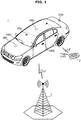
- FIG. 1 shows a vehicle, according to embodiments of the present disclosure.
- a vehicle 1 may include a car body forming the exterior of the vehicle 1 and accommodating the driver and/or baggage, a chassis including parts of the vehicle 1 other than the car body, and electronic parts for protecting the driver or giving convenience to the driver.
- the car body may form interior space, in which the driver may stay, an engine room for accommodating an engine, and a trunk room for accommodating baggage.
- the chassis may include devices for generating power to drive the vehicle 1 and driving/braking/steering the vehicle 1 with the power, under the control of the driver.
- the electronic parts may control the vehicle 1 and provide safety and convenience for the driver and passengers.
- the vehicle 1 may receive radio signals from a base station 2 and communicate with a user identification device 3.
- the vehicle 1 may receive a low frequency (LF) signal having a first frequency.
- the LF signal may refer to a radio signal having a frequency ranging from about 30KHz to about 300KHz.
- the vehicle 1 may receive a radio signal having a frequency of about 65KHz from the base station 2.
- the LF signal received by the vehicle 1 from the base station 2 may include information indicating a current time.
- the vehicle 1 may correct the current time of the clock of the vehicle 1 based on the LF signal received from the base station 2.
- the LF signal received by the vehicle 1 from the base station 2 may include a disaster broadcast signal.
- the vehicle 1 may reproduce the disaster broadcast signal included in the LF signal.
- the vehicle 1 may exchange radio frequency (RF) signals with the user identification device 3.
- RF signals may refer to radio signals having frequencies ranging from about 3KHz to about 300GHz.
- the user identification device 3 may be a key fob connected to the vehicle 1 via cable or wirelessly to unlock the doors or start the engine to drive the vehicle 100.
- the user identification device 3 is not limited to the key fob, but may include any input device that may control the vehicle 1 to unlock the doors and start the engine to drive the vehicle 100.
- the user identification device 3 may include the mobile device.
- an application to execute operation as the user identification device 3 may be installed in the mobile device, in which case the application may be installed before the mobile device is released or may be downloaded from a server after the mobile device is released.
- the mobile device may go through an authentication process to operate as the user identification device 3 for the vehicle 1.
- the vehicle 1 may exchange RF signals with the user identification device 3 to authenticate the user identification device 3.
- the vehicle 1 may transmit an LF signal to the user identification device 3.
- the vehicle 1 may transmit an LF signal having the first frequency.
- the vehicle 1 may transmit an LF signal having a frequency of about 125KHz to the user identification device 3.
- the user identification device 3 may transmit an ultra-high frequency (UHF) signal having a third frequency.
- UHF ultra-high frequency
- the UHF signal may refer to a signal ranging from about 300MHz to about 3GHz.
- the user identification device 3 may transmit the UHF signal of about 433MHz to the vehicle 1.
- the vehicle 1 may receive the UHF signal from the user identification device 3, and based on the received UHF signal, authenticate the user identification device 3.
- the vehicle 1 may include a plurality of LF transceivers 100a, 100b, 100c, 100d, and 100e (collectively, 100) for receiving an LF signal from the base station 2 and transmit an LF signal to the user identification device 3, and a UHF receiver 200 for receiving a UHF signal from the user identification device 3.
- a plurality of LF transceivers 100a, 100b, 100c, 100d, and 100e (collectively, 100) for receiving an LF signal from the base station 2 and transmit an LF signal to the user identification device 3, and a UHF receiver 200 for receiving a UHF signal from the user identification device 3.
- the UHF receiver 200 may be installed under the dashboard of the vehicle 1, i.e., inside the vehicle 1.
- the plurality of LF transceivers 100 may be installed in various positions at the vehicle 1.
- some of the plurality of LF transceivers 100 may be installed on the outer side of the vehicle 1, such as on handles of the left and right doors of the vehicle 1 and on the trunk of the vehicle 1, as shown in FIG. 1 , and some others may be installed inside the vehicle 1, such as at the dashboard of the vehicle 1, at an indoor light of the vehicle 1, etc.
- Some of the plurality of LF transceivers 100 may receive an LF signal from the base station 2 and transmit an LF signal to the user identification device 3, and some others of the plurality of LF transceivers 100 may only transmit an LF signal to the user identification device 3.
- the LF transceivers 100a, 100b, and 100c installed on the outer side of the vehicle 1 may receive an LF signal from the base station 2 and transmit an LF signal to the user identification device 3, while the LF transceivers 100d and 100e installed inside the vehicle 1 may only transmit an LF signal to the user identification device 3.
- FIG. 2 is a configuration of a vehicle, according to embodiments of the present disclosure.
- FIG. 3 shows LF signals transmitted and received by a vehicle, according to embodiments of the present disclosure.
- the vehicle 1 may include an LF antenna 110, an LF receiver 120, an LF transmitter 130, a UHF antenna 210, a UHF receiver 220, and a controller 10.
- the LF antenna 110 may receive an LF signal of a first frequency from the free space and transmit an LF signal of the first frequency to the free space.
- the LF antenna 110 may receive an LF signal of the first frequency from the base station 2, and forward the received LF signal to the LF receiver 120.
- the LF antenna 110 may also receive an LF signal from the LF transmitter 130 and transmit the LF signal of a second frequency to the user identification device 3.
- the first frequency of the LF signal received by the LF antenna 110 and the second frequency of the LF signal transmitted by the LF antenna 110 may be different from each other.
- the LF antenna 110 may receive an LF signal of 65KHz from the base station 2 and transmit an LF signal of 125KHz to the user identification device 3.
- the frequency of a signal to be transmitted or received by the antenna may depend on the figure of the antenna, especially, the length of the antenna. Accordingly, to transmit and receive different frequencies of signals, the LF antenna 110 may have varying length. A specific figure of the LF antenna 110 will be described in detail later.
- the LF receiver 120 may process the LF signal received through the LF antenna 110. For example, the LF receiver 120 may extract information included in the LF signal by demodulating the LF signal received through the LF antenna 110.
- the LF signal may be modulated in various modulation schemes, such as amplitude modulation (AM), frequency modulation (FM), phase modulation (PM), amplitude-shift keying (ASK), frequency-shift keying (FSK), phase-shaft keying (PSK), pulse modulation, etc.
- AM amplitude modulation
- FM frequency modulation
- PM phase modulation
- ASK amplitude-shift keying
- FSK frequency-shift keying
- PSK phase-shaft keying
- the LF receiver 120 may acquire data included in the LF signal by demodulating the LF signal. For example, the LF receiver 120 may acquire information indicating a current time by demodulating the LF signal and forward the information indicating a current time to the controller 10.
- the LF transmitter 130 may create an LF signal by modulating data received from the controller 10, and send the LF signal to the LF antenna 110.
- the LF transmitter 130 may create the LF signal by modulating the data.
- the LF transmitter 130 may modulate the data in various modulation schemes, such as AM, FM, PM, ASK, FSK, PSK, and pulse modulation, etc.
- the data modulated by the LF transmitter 130 may include information indicating a current time.
- the LF transmitter 130 may receive the information indicating the current time from the controller 10, and create an LF signal by modulating the information indicating the current time.
- the UHF antenna 210 may receive a UHF signal from the free space.
- the UHF antenna 210 may receive a UHF signal from the user identification device 3 through the free space, and forward the received UHF signal to the UHF receiver 220.
- the UHF receiver 220 may process the UHF signal received through the UHF antenna 210. For example, the UHF receiver 220 may extract information included in the UHF signal by demodulating the UHF signal received through the UHF antenna 210.
- the UHF signal may be modulated in various modulation schemes, such as AM, FM, PM, ASK, FSK, PSK, and pulse modulation, etc.
- the UHF receiver 220 may acquire data included in the UHF signal by demodulating the UHF signal.
- the UHF receiver 220 may acquire identification information and one-time password of the user identification device 3 by demodulating the UHF signal.
- the vehicle 1 may receive the information indicating a current time from the base station 2 and transmit the information indicating the current information to the user identification device 3.
- the user identification device 3 may create a one-time password based on the information indicating the current time received from the vehicle 1. For example, the user identification device 3 may input the indicating the current time to a pre-stored function, and create a one-time password based on the output of the function. Furthermore, the user identification device 3 may input the information indicating the current time to pre-stored look-up data, and create a one-time password based on a search result of the look-up data.
- the user identification device 3 may create a UHF signal by modulating the one-time password, and transmit the UHF signal to the vehicle 1.
- the UHF receiver 220 may forward the one-time password acquired from the UHF signal to the controller 10.
- the controller 10 may send and receive LF signals in every predetermined period P.
- the controller 10 may control the LF receiver 120 and the LF transmitter 130 to alternately perform reception and transmission of LF signals during the predetermined period P.
- the controller 10 may control the LF receiver 120 and the LF transmitter 130 to avoid time-overlap between reception and transmission of the LF signals.
- the controller 10 may control the LF receiver 120 to receive an LF signal from the base station 2 during first time T1 in a predetermined period, and control the LF transmitter 130 to transmit an LF signal to the user identification device 3 during second time T2 in the predetermined period.
- the controller 10 may repeat reception of the LF signal during the first time T1 and transmission of the LF signal during the second time T2.
- the controller 10 may send an activation signal to the LF receiver 120 in the every predetermined period P, and the LF receiver 120 may receive an LF signal during the first time in response to the activation signal from the controller 10.
- the controller 10 may receive information indicating a current time from the LF receiver 120, which receives the information during the first time.
- the controller 10 may create a one-time password based on the information indicating a current time. For example, the controller 10 may input the information indicating the current time to a pre-stored function, and create a one-time password based on the output of the function. Furthermore, the controller 10 may input the information indicating the current time to pre-stored look-up data, and create a one-time password based on a search result of the look-up data.
- the controller 10 may send an activation signal to the LF transmitter 130 in the every predetermined period P, and the LF transmitter 130 may transmit an LF signal during the second time in response to the activation signal from the controller 10. Furthermore, the LF transmitter 130 may transmit the information indicating a current time to the user identification device 3 during the second time.
- the user identification device 3 may create one-time password based on the information indicating the current time received from the LF transmitter 130, and create a UHF signal by modulating the one-time password.
- the user identification device 3 may transmit the UHF signal to the vehicle 1, and the UHF receiver 220 may receive the UHF signal through the UHF antenna 210 and acquire the one-time password by demodulating the UHF signal.
- the controller 10 may receive the one-time password demodulated from the UHF signal from the UHF receiver 220.
- the controller 10 may compare the one-time password received from the UHF receiver 220 (hereinafter, called “first one-time password”) with the one-time password created by the controller 10 (hereinafter, called “second one-time password”), and determine whether the first one-time password is identical to the second one-time password.
- the controller 10 may authenticate the user identification device 3, unlock the doors under the control of the user identification device 3, and start the vehicle 1 at a start command from the driver.
- the controller 10 may not authenticate the user identification device 3 nor process the signal from the user identification device 3.
- the controller 10 may include a memory 12 for storing control programs and data to control the operation of the vehicle 1, and a processor 11 for processing the data according to the control program stored in the memory 12.
- the memory 12 may store control programs to control the LF receiver 120, LF transmitter 130, and UHF receiver 220, and functions/look-up tables for creating a one-time password from the current time.
- the memory 12 may temporarily store data received from the LF receiver 120 and UHF receiver 220, and provide the data to the processor 11 according to an instruction of the processor 11. Furthermore, the memory 12 may temporarily store data created by the processor 11 until the data is sent to the LF transmitter 130.
- the memory 12 may include a non-volatile memory, such as a Read Only Memory (ROM), a flash memory, and/or the like, which may store data for a long period, and a volatile memory, such as a static random access memory (SRAM), a dynamic RAM (DRAM), or the like, which may temporarily store data.
- ROM Read Only Memory
- SRAM static random access memory
- DRAM dynamic RAM
- the processor 11 may process the data stored in the memory 12 according to a program (a series of instructions) stored in the memory 12, and provide the resultant data of the process back to the memory 12.
- the processor 11 may alternately create the activation signal to activate the LF receiver 120 and the activation signal to activate the LF transmitter 130 in the every predetermined period P.
- the processor 11 may create the second one-time password from the information indicating a current time received from the LF receiver 120.
- the processor 11 may compare the first one-time password received from the UHF receiver 220 with the second one-time password. If the first one-time password is identical to the second one-time password, the processor 11 may create a signal to unlock the doors of the vehicle 1 and/or a signal to start the vehicle 1.
- the processor 11 may include an operation circuit for performing logic operation and arithmetic operation, and a memory circuit for storing the data resulting from the operation.
- FIG. 4 is a block diagram of an LF transceiver included in a vehicle, according to embodiments of the present disclosure.
- the vehicle 1 may include the plurality of LF transceivers 100.
- the plurality of LF transceivers 100 may each include the LF antenna 110, a first capacitor 141, the LF transmitter 130, a second capacitor 142, a filter 150, and the LF receiver 120, as shown in FIG. 4 .
- the LF antenna 110 may include a first inductor 111 and a second inductor 112, which are separable from each other and connected in series.
- the LF antenna 110 may include a first terminal N1, a second terminal N2, and a third terminal N3.
- the first inductor 111 is arranged between the first and second terminals N1 and N2, and the second inductor 112 is arranged between the second and third terminals N2 and N3.
- the first and second inductors 111 and 112 may join at the second terminal N2.
- the first and second inductors 111 and 112 may each produce an electromagnetic field in response to an alternate current (AC) signal.
- the first and second inductors 111 and 112 may each receive an LF signal and radiate an electromagnetic field having an LF frequency into the free space.
- the first and second inductors 111 and 112 may each receive an electromagnetic field of the LF frequency from the free space and create an LF signal in response to the received electromagnetic field.
- the first inductor 111 may have first inductance L1
- the second inductor 112 may have second inductance L2.
- the first capacitor 141 may be arranged between the first and third terminals N1 and N3 of the LF antenna 110. One end of the first capacitor 141 may be connected to the first terminal N1 of the LF antenna 110, and the other end of the first capacitor 141 may be connected to the third terminal N3 of the LF antenna 110.
- the first capacitor 141 may have first capacitance C1.
- the first capacitor 141 may be resonated with the first and second inductors 111 and 112 arranged between the first and third terminals N1 and N3.
- the first resonance frequency f1 may be approximately 65KHz.
- the second capacitor 142 may be arranged between the second and third terminals N2 and N3 of the LF antenna 110. One end of the second capacitor 142 may be connected to the second terminal N2 of the LF antenna 110, and the other end of the second capacitor 142 may be connected to the third terminal N3 of the LF antenna 110.
- the second capacitor 142 may have second capacitance C2.
- the second capacitor 142 may be resonated with the second inductor 112.
- the second resonance frequency f2 may be approximately 125KHz.
- the filter 150 may be connected to both ends of the first capacitor 141 and connected to the LF receiver 120. Specifically, input ends of the filter 150 may be connected to both ends of the first capacitor 141 and output ends of the filter 150 may be connected to input ends of the LF receiver 120.
- the filter 150 may cut off the LF signal of the first resonance frequency f1 output from the LF transmitter 130.
- the filter 150 may include a band pass filter (BPF) that passes LF signals having the second resonance frequency f2.
- BPF band pass filter
- LPF low pass filter
- the LF receiver 120 may be connected to the resonant circuit including the first capacitor 141 and the first and second inductors 111 and 112 via the filter 150. Specifically, the input ends of the LF receiver 120 may be connected to both ends of the first capacitor 141 via the filter 150.
- the LF receiver 120 may receive an LF signal having the first resonance frequency f1 from the first capacitor 141 under the control of the controller 10.
- the first capacitor 141 and the first and second inductors 111 and 112 may acquire electromagnetic waves of the first resonance frequency f1 from the free space, and the LF receiver 120 may receive an LF signal of the first resonance frequency f1 from the first capacitor 141.
- the LF transmitter 130 may be connected to the resonant circuit including the second capacitor 142 and the second inductor 112. Specifically, the output ends of the LF transmitter 130 may be connected to both ends of the second capacitor 142.
- the LF transmitter 130 may provide an LF signal having the second resonance frequency f2 to the second capacitor 142 under the control of the controller 10.
- the second capacitor 142 and the second inductor 112 are resonated according to the LF signal having the second resonance frequency f2 output from the LF transmitter 130, and electromagnetic waves of the first resonance frequency f1 may be radiated into the free space from the second inductor 112.
- FIG. 5 is a flowchart illustrating a first control method of a vehicle, according to embodiments of the present disclosure.
- the vehicle 1 receives an LF signal during the first time, in 1010.
- the controller 10 of the vehicle 1 may control the LF receiver 120 to receive an LF signal from the base station 2 during the first time T1 in a predetermined period.
- the LF receiver 120 may receive an LF signal having the first resonance frequency f1 from the LF antenna 110 under the control of the controller 10, and output the LF signal of the first resonance frequency f1 to the controller 10.
- the LF signal received from the base station 2 may include information indicating a current time.
- the vehicle 1 corrects current time based on the information indicating the current time, in 1020.
- the controller 10 may store the current time indicating present time, and compare the current time with the information indicating the current time included in the LF signal. If the current time is different from the information indicating the current time, the controller 10 may correct the current time based on the information indicating the current time.
- the vehicle 1 creates the second one-time password, in 1030.
- the controller 10 may create the second one-time password based on the corrected current time. For example, the controller 10 may input the information indicating the current time to a pre-stored function, and create the second one-time password based on the output of the function. Furthermore, the controller 10 may input the information indicating the current time to pre-stored look-up data, and create the second one-time password based on a search result of the look-up data.
- the vehicle 1 transmits an LF signal during the second time, in 1040.
- the controller 10 may control the LF transmitter 130 to transmit the LF signal to the user identification device 3 during the second time T2 in the predetermined period.
- the LF transmitter 130 may send the LF signal having the second resonance frequency f2 to the LF antenna 110 under the control of the controller 10, and the LF antenna 110 may emit the LF signal of the second resonance frequency f2 to the free space.
- the LF signal transmitted to the user identification device 3 may include information indicating the current time.
- FIG. 6 is a flowchart illustrating a second control method of a vehicle, according to embodiments of the present disclosure.
- the vehicle 1 receives a UHF signal, in 1110.
- the controller 10 of the vehicle 1 may receive the UHF signal from the user identification device 3 through the UHF antenna 210 and UHF receiver 220.
- the UHF signal may include identification information and first one-time password of the user identification device 3.
- the user identification device 3 may create the first one-time password based on the information indicating a current time included in the LF signal received from the vehicle 1.
- the user identification device 3 may create a UHF signal by modulating the one-time password, and transmit the UHF signal to the vehicle 1.
- the vehicle 1 compares the first one-time password included in the UHF signal and the second one-time password created in advance, in 1120.
- the controller 10 may create the second one-time password based on the information indicating the current time received from the LF receiver 120, and acquire the first one-time password of the user identification device 3 from the UHF receiver 220.
- the controller 10 may compare the first one-time password of the user identification device 3 with the second one-time password.
- the controller 10 authenticates the user of the user identification device 3, in 1130.
- the controller 10 may authenticate the user identification device 3, unlock the doors under the control of the user identification device 3, and start the vehicle 1 at a start command from the driver.
- FIG. 7 is another configuration of a vehicle, according to embodiments of the present disclosure.
- the vehicle 1 may include the LF antenna 110, the LF receiver 120, the LF transmitter 130, the UHF antenna 210, the UHF receiver 220, the controller 10, and a switch module 160.
- the LF antenna 110, LF receiver 120, LF transmitter 130, UHF antenna 210, and UHF receiver 220 may be the same as those shown in FIG. 2 .
- the switch module 160 may connect the LF antenna 110 selectively to one of the LF receiver 120 and the LF transmitter 130, under the control of the controller 10. For example, the switch module 160 may connect the LF antenna 110 to the LF receiver 120 to receive an LF signal from the base station 2 during the first time T1 in the predetermined period. The switch module 160 may connect the LF antenna 110 to the LF transmitter 130 to transmit an LF signal to the user identification device 3 during the second time T2 in the predetermined period.
- the switch module 160 may include at least one switching device, e.g., a Metal Oxide Semiconductor Field Effect transistor (MOSFET), a Bipolar Junction Transistor (BJT), etc.
- MOSFET Metal Oxide Semiconductor Field Effect transistor
- BJT Bipolar Junction Transistor
- the controller 10 may control the switch module 160 for the LF receiver 120 to receive an LF signal from the base station 2 during the first time T1 in a predetermined period, and control the switch module 160 for the LF transmitter to transmit an LF signal to the user identification device 3 during the second time T2 in the predetermined period.
- FIG. 8 is another block diagram of an LF transceiver included in a vehicle, according to embodiments of the present disclosure.
- the vehicle 1 may include the plurality of LF transceivers 100.
- the plurality of LF transceivers 100 may each include the LF antenna 110, the switch module 160, the first capacitor 141, the LF transmitter 130, the second capacitor 142, and the LF receiver 120, as shown in FIG. 8 .
- the LF antenna 110 may include the first inductor 111 and the second inductor 112, which are separable from each other and connected in series.
- the LF antenna 110 may include the first terminal N1, the second terminal N2, the third terminal N3, and a fourth terminal.
- the first inductor 111 is arranged between the first and second terminals N1 and N2, and the second inductor 112 is arranged between the third and fourth terminals N3 and N4.
- first and second inductors 111 and 112 may be the same as those of the first and second inductors shown in FIG. 4 .
- the first inductor 111 may have first inductance L1
- the second inductor 112 may have second inductance L2.
- the first capacitor 141 may be arranged between the first and fourth terminals N1 and N4 of the LF antenna 110. One end of the first capacitor 141 may be connected to the first terminal N1 of the LF antenna 110, and the other end of the first capacitor 141 may be connected to the fourth terminal N4 of the LF antenna 110.
- the first capacitor 141 may have first capacitance C1.
- the first capacitor 141 may be resonated with the first and second inductors 111 and 112 arranged between the first and fourth terminals N1 and N4.
- the second capacitor 142 may be arranged between the fourth terminal N4 of the LF antenna 110 and the switch module 160. One end of the second capacitor 142 may be connected to the fourth terminal N4 of the LF antenna 110, and the other end of the second capacitor 142 may be connected to the switch module 160.
- the second capacitor 142 may have second capacitance C2.
- the second capacitor 142 may be resonated with the second inductor 112 according to an operation of the switch module 160.
- the LF transceiver shown in FIG. 8 may not include a filter.
- the LF receiver 120 may be connected to the resonant circuit including the first capacitor 141 and the first and second inductors 111 and 112. Specifically, the input ends of the LF receiver 120 may be connected to both ends of the first capacitor 141.
- the function of the LF receiver 120 may be the same as that of the LF receiver shown in FIG. 4 .
- the LF transmitter 130 may be connected to the resonant circuit including the second capacitor 142 and the second inductor 112. Specifically, the output ends of the LF transmitter 130 may be connected to both ends of the second capacitor 142.
- the function of the LF transmitter 130 may be the same as that of the LF transmitter shown in FIG. 4 .
- the switch module 160 may be provided between the first inductor 111, the second inductor 112, and the second capacitor 142.
- the switch module 160 may allow connection between the first and second inductors 111 and 112 while disconnecting the second inductor 112 from the second capacitor 142, according to a control signal from the controller 10. Furthermore, the switch module 160 may disconnect the first inductor 111 from the second inductor 112 while allowing connection between the second inductor 112 and the second capacitor 142, according to a control signal from the controller 10.
- the switch module 160 may include a first switch 161 arranged between the second and third terminals N2 and N3 of the LF antenna 110, and a second switch 162 arranged between the third terminal N3 of the LF antenna 110 and the second capacitor 142.
- the second inductor 112 When the first switch 161 is turned on (closed), the second inductor 112 may be connected to the first inductor 111, and when the second switch 162 is turned on (closed), the second inductor 112 may be connected to the second capacitor 142.
- the second inductor 112 When the first switch 161 is turned on (closed) and the second switch 162 is turned off (opened), the second inductor 112 may be connected to the first inductor 111 and the second inductor 112 may be disconnected from the second capacitor 142. Accordingly, while the first capacitor 141 is resonated with the first and second inductors 111 and 112, the resonance signal is protected from distortion by the second capacitor 142.
- the second inductor 112 When the first switch 161 is turned off (opened) and the second switch 162 is turned on (closed), the second inductor 112 may be disconnected from the first inductor 111 and the second inductor 112 may be connected to the second capacitor 142. Accordingly, while the second capacitor 142 is resonated with the second inductor 112, the resonance signal is not input to the LF receiver 120.
- the vehicle 1 including the LF transceiver 100 may receive an LF signal having the first frequency from the base station 2 through the LF transceiver 100 and transmit an LF signal having the second frequency to the user identification device 3 through the LF transceiver 100.
- the LF signal having the first frequency and the LF signal having the second frequency may each have information indicating a current time, and the vehicle 1 may create an one-time password based on the information indicating the current time and compare the one-time password with a one-time password received from the user identification device 3 to authenticate the user identification device 3.
- a vehicle, a control method thereof, and a transceiver for the vehicle capable of enhancing security may be provided.
- a vehicle, a control method thereof, and a transceiver for the vehicle which authenticates a user identification device using a one-time password may be provided.
- a vehicle, a control method thereof, and a transceiver for the vehicle which creates a one-time password based on information indicating a current time included in a broadcast signal may be provided.
Landscapes
- Engineering & Computer Science (AREA)
- Computer Networks & Wireless Communication (AREA)
- Computer Security & Cryptography (AREA)
- Mechanical Engineering (AREA)
- Signal Processing (AREA)
- Physics & Mathematics (AREA)
- General Physics & Mathematics (AREA)
- Radar, Positioning & Navigation (AREA)
- Remote Sensing (AREA)
- Lock And Its Accessories (AREA)
Abstract
Description
- The present disclosure relates to a vehicle, a control method thereof, and a transceiver for the vehicle, and more particularly, to a vehicle, a control method thereof, and a transceiver for the vehicle capable of enhancing security.
- Many modern vehicles are equipped with various electronic devices for the purpose of enhancing driver convenience. Among them, a user identification device (UID), e.g., a smart key, is often used to identify the driver. The vehicle can authenticate the driver using the UID, and can restrict vehicle control (e.g., acceleration control, steering control, braking control, etc.) to authenticated drivers.
- Conventionally, the vehicle authenticates the UID of the driver with a unique identification code and a sequentially changing rolling code of the UID. However, this type of authentication of the UID is often vulnerable to security issues.
- The present disclosure provides a vehicle, a control method thereof, and a transceiver for the vehicle for the enhancement of security.
- The present disclosure also provides a vehicle, a control method thereof, and a transceiver for the vehicle, which authenticates a user identification device using a one-time password (OTP).
- The present disclosure also provides a vehicle, a control method thereof, and a transceiver for the vehicle, which creates the OTP based on information indicating a current time included in a broadcast signal.
- In accordance with embodiments of the present disclosure, a vehicle may include: a first antenna; a first receiver configured to receive a first radio signal through the first antenna, the first radio signal having a first frequency; a transmitter configured to transmit a second radio signal through the first antenna, the second radio signal having a second frequency; and a controller configured to acquire information indicating a current time included in the first radio signal, and to control operation of the transmitter so as to transmit the second radio signal including the information indicating the current time.
- The controller may control operation of the first receiver and the operation of the transmitter, respectively, so as to alternately receive the first radio signal and transmit the second radio signal.
- The controller may control the operation of the first receiver so as to receive the first radio signal during a first time in a predetermined period, and to control the operation of the transmitter so as to transmit the second radio signal during a second time in the predetermined period.
- The vehicle may further include a second antenna and a second receiver configured to receive a third radio signal through the second antenna, the third radio signal having a third frequency. The controller may acquire a first one-time password included in the third radio signal.
- The controller may create a second one-time password based on the information indicating the current time, and control operation of the vehicle according to a control instruction included in the third radio signal when the first one-time password is identical to the second one-time password.
- The vehicle may further include a first capacitor and a second capacitor. The first antenna may include a first inductor and a second inductor connected in series, the first capacitor is connected to the first and second inductors, and the second capacitor may be connected to the second inductor.
- The first frequency may correspond to a resonance frequency between the first and second inductors and the first capacitor, and the second frequency may correspond to a resonance frequency between the second inductor and the second capacitor.
- An input of the first receiver may be connected to the first capacitor and an output of the transmitter may be connected to the second capacitor.
- The vehicle may further include a filter disposed between the input of the first receiver and the first capacitor, the filter configured to cut off a radio signal having the second frequency.
- The vehicle may further include a switch module configured to selectively connect the second inductor to one of the first inductor and the second capacitor.
- Furthermore, in accordance with embodiments of the present disclosure, a control method of a vehicle having a first antenna may include: receiving, through the first antenna, a first radio signal having a first frequency, the first radio signal including information indicating a current time; and transmitting, through the first antenna, a second radio signal having a second frequency, the second radio signal including the information indicating the current time.
- Reception of the first radio signal and transmission of the second radio signal may be performed alternately.
- The reception of the first radio signal may be performed during a first time in a predetermined period and the transmission of the second radio signal may be performed during a second time in the predetermined period.
- The control method may further include receiving a third radio signal having a third frequency; and acquiring a first one-time password included in the third radio signal.
- The control method may further include creating a second one-time password based on the information indicating the current time; and controlling operation of the vehicle according to a control instruction included in the third radio signal when the first one-time password is identical to the second one-time password.
- Furthermore, in accordance with embodiments of the present disclosure, a transceiver for a vehicle may include: an antenna having a first inductor and a second inductor connected in series; a first capacitor connected to the first and second inductors; a receiver connected to the first capacitor; a second capacitor connected to the second inductor; and a transmitter connected to the second capacitor. The receiver may be configured to receive a first radio signal through the antenna, the first radio signal having a first frequency, and the transmitter may be configured to transmit a second radio signal through the antenna, the second radio signal having a second frequency.
- The first frequency may correspond to a resonance frequency between the first and second inductors and the first capacitor, and the second frequency may correspond to a resonance frequency between the second inductor and the second capacitor.
- The transceiver for vehicle may further include a filter disposed between the receiver and the first capacitor, the filter configured to cut off a radio signal having the second frequency.
- The transceiver for vehicle may further include a switch module configured to selectively connect the second inductor to one of the first inductor and the second capacitor.
- The above and other objects, features and advantages of the present disclosure will become more apparent to those of ordinary skill in the art by describing in detail exemplary embodiments thereof with reference to the accompanying drawings, in which:
-
FIG. 1 shows a vehicle, according to an embodiment of the present disclosure; -
FIG. 2 is a configuration of a vehicle, according to embodiments of the present disclosure; -
FIG. 3 shows low frequency (LF) signals transmitted and received by a vehicle, according to embodiments of the present disclosure; -
FIG. 4 is a block diagram of an LF transceiver included in a vehicle, according to embodiments of the present disclosure; -
FIG. 5 is a flowchart illustrating a first control method of a vehicle, according to embodiments of the present disclosure; -
FIG. 6 is a flowchart illustrating a second control method of a vehicle, according to embodiments of the present disclosure; -
FIG. 7 is another configuration of a vehicle, according to embodiments of the present disclosure; and -
FIG. 8 is another block diagram of an LF transceiver included in a vehicle, according to embodiments of the present disclosure. - It should be understood that the above-referenced drawings are not necessarily to scale, presenting a somewhat simplified representation of various preferred features illustrative of the basic principles of the disclosure. The specific design features of the present disclosure, including, for example, specific dimensions, orientations, locations, and shapes, will be determined in part by the particular intended application and use environment.
- Hereinafter, embodiments of the present disclosure will be described in detail with reference to the accompanying drawings. As those skilled in the art would realize, the described embodiments may be modified in various different ways, all without departing from the spirit or scope of the present disclosure. Further, throughout the specification, like reference numerals refer to like elements.
- The terminology used herein is for the purpose of describing particular embodiments only and is not intended to be limiting of the disclosure. As used herein, the singular forms "a," "an," and "the" are intended to include the plural forms as well, unless the context clearly indicates otherwise. It will be further understood that the terms "comprises" and/or "comprising," when used in this specification, specify the presence of stated features, integers, steps, operations, elements, and/or components, but do not preclude the presence or addition of one or more other features, integers, steps, operations, elements, components, and/or groups thereof. As used herein, the term "and/or" includes any and all combinations of one or more of the associated listed items.
- It is understood that the term "vehicle" or "vehicular" or other similar term as used herein is inclusive of motor vehicles in general such as passenger automobiles including sports utility vehicles (SUV), buses, trucks, various commercial vehicles, watercraft including a variety of boats and ships, aircraft, and the like, and includes hybrid vehicles, electric vehicles, plug-in hybrid electric vehicles, hydrogen-powered vehicles and other alternative fuel vehicles (e.g., fuels derived from resources other than petroleum). As referred to herein, a hybrid vehicle is a vehicle that has two or more sources of power, for example both gasoline-powered and electric-powered vehicles.
- Additionally, it is understood that one or more of the below methods, or aspects thereof, may be executed by at least one controller. The term "controller" may refer to a hardware device that includes a memory and a processor. The memory is configured to store program instructions, and the processor is specifically programmed to execute the program instructions to perform one or more processes which are described further below. The controller may control operation of units, modules, parts, devices, or the like, as described herein. Moreover, it is understood that the below methods may be executed by an apparatus comprising the controller in conjunction with one or more other components, as would be appreciated by a person of ordinary skill in the art.
- Furthermore, the controller of the present disclosure may be embodied as non-transitory computer readable media containing executable program instructions executed by a processor. Examples of the computer readable mediums include, but are not limited to, ROM, RAM, compact disc (CD)-ROMs, magnetic tapes, floppy disks, flash drives, smart cards and optical data storage devices. The computer readable recording medium can also be distributed throughout a computer network so that the program instructions are stored and executed in a distributed fashion, e.g., by a telematics server or a Controller Area Network (CAN).
- The principle and embodiments of the present disclosure will now be described with reference to accompanying drawings.
-
FIG. 1 shows a vehicle, according to embodiments of the present disclosure. - As shown in
FIG. 1 , avehicle 1 may include a car body forming the exterior of thevehicle 1 and accommodating the driver and/or baggage, a chassis including parts of thevehicle 1 other than the car body, and electronic parts for protecting the driver or giving convenience to the driver. The car body may form interior space, in which the driver may stay, an engine room for accommodating an engine, and a trunk room for accommodating baggage. The chassis may include devices for generating power to drive thevehicle 1 and driving/braking/steering thevehicle 1 with the power, under the control of the driver. The electronic parts may control thevehicle 1 and provide safety and convenience for the driver and passengers. - The
vehicle 1 may receive radio signals from abase station 2 and communicate with auser identification device 3. - The
vehicle 1 may receive a low frequency (LF) signal having a first frequency. The LF signal may refer to a radio signal having a frequency ranging from about 30KHz to about 300KHz. For example, thevehicle 1 may receive a radio signal having a frequency of about 65KHz from thebase station 2. - The LF signal received by the
vehicle 1 from thebase station 2 may include information indicating a current time. Thevehicle 1 may correct the current time of the clock of thevehicle 1 based on the LF signal received from thebase station 2. - In addition, the LF signal received by the
vehicle 1 from thebase station 2 may include a disaster broadcast signal. Thevehicle 1 may reproduce the disaster broadcast signal included in the LF signal. - The
vehicle 1 may exchange radio frequency (RF) signals with theuser identification device 3. The RF signals may refer to radio signals having frequencies ranging from about 3KHz to about 300GHz. - The
user identification device 3 may be a key fob connected to thevehicle 1 via cable or wirelessly to unlock the doors or start the engine to drive the vehicle 100. - The
user identification device 3 is not limited to the key fob, but may include any input device that may control thevehicle 1 to unlock the doors and start the engine to drive the vehicle 100. For example, if a mobile device serves as theuser identification device 3, theuser identification device 3 may include the mobile device. For this, an application to execute operation as theuser identification device 3 may be installed in the mobile device, in which case the application may be installed before the mobile device is released or may be downloaded from a server after the mobile device is released. Furthermore, the mobile device may go through an authentication process to operate as theuser identification device 3 for thevehicle 1. - The
vehicle 1 may exchange RF signals with theuser identification device 3 to authenticate theuser identification device 3. - The
vehicle 1 may transmit an LF signal to theuser identification device 3. Thevehicle 1 may transmit an LF signal having the first frequency. For example, thevehicle 1 may transmit an LF signal having a frequency of about 125KHz to theuser identification device 3. - In response to the LF signal having the first frequency sent from the
vehicle 1, theuser identification device 3 may transmit an ultra-high frequency (UHF) signal having a third frequency. The UHF signal may refer to a signal ranging from about 300MHz to about 3GHz. Theuser identification device 3 may transmit the UHF signal of about 433MHz to thevehicle 1. - The
vehicle 1 may receive the UHF signal from theuser identification device 3, and based on the received UHF signal, authenticate theuser identification device 3. - The
vehicle 1 may include a plurality ofLF transceivers base station 2 and transmit an LF signal to theuser identification device 3, and aUHF receiver 200 for receiving a UHF signal from theuser identification device 3. - The
UHF receiver 200 may be installed under the dashboard of thevehicle 1, i.e., inside thevehicle 1. - By contrast, the plurality of LF transceivers 100 may be installed in various positions at the
vehicle 1. For example, some of the plurality of LF transceivers 100 may be installed on the outer side of thevehicle 1, such as on handles of the left and right doors of thevehicle 1 and on the trunk of thevehicle 1, as shown inFIG. 1 , and some others may be installed inside thevehicle 1, such as at the dashboard of thevehicle 1, at an indoor light of thevehicle 1, etc. - Some of the plurality of LF transceivers 100 may receive an LF signal from the
base station 2 and transmit an LF signal to theuser identification device 3, and some others of the plurality of LF transceivers 100 may only transmit an LF signal to theuser identification device 3. For example, the LF transceivers 100a, 100b, and 100c installed on the outer side of thevehicle 1 may receive an LF signal from thebase station 2 and transmit an LF signal to theuser identification device 3, while theLF transceivers vehicle 1 may only transmit an LF signal to theuser identification device 3. -
FIG. 2 is a configuration of a vehicle, according to embodiments of the present disclosure.FIG. 3 shows LF signals transmitted and received by a vehicle, according to embodiments of the present disclosure. - As shown in
FIGS. 2 and3 , thevehicle 1 may include anLF antenna 110, anLF receiver 120, anLF transmitter 130, aUHF antenna 210, aUHF receiver 220, and acontroller 10. - The
LF antenna 110 may receive an LF signal of a first frequency from the free space and transmit an LF signal of the first frequency to the free space. For example, theLF antenna 110 may receive an LF signal of the first frequency from thebase station 2, and forward the received LF signal to theLF receiver 120. TheLF antenna 110 may also receive an LF signal from theLF transmitter 130 and transmit the LF signal of a second frequency to theuser identification device 3. - The first frequency of the LF signal received by the
LF antenna 110 and the second frequency of the LF signal transmitted by theLF antenna 110 may be different from each other. For example, theLF antenna 110 may receive an LF signal of 65KHz from thebase station 2 and transmit an LF signal of 125KHz to theuser identification device 3. As already known in the art, the frequency of a signal to be transmitted or received by the antenna may depend on the figure of the antenna, especially, the length of the antenna. Accordingly, to transmit and receive different frequencies of signals, theLF antenna 110 may have varying length. A specific figure of theLF antenna 110 will be described in detail later. - The
LF receiver 120 may process the LF signal received through theLF antenna 110. For example, theLF receiver 120 may extract information included in the LF signal by demodulating the LF signal received through theLF antenna 110. The LF signal may be modulated in various modulation schemes, such as amplitude modulation (AM), frequency modulation (FM), phase modulation (PM), amplitude-shift keying (ASK), frequency-shift keying (FSK), phase-shaft keying (PSK), pulse modulation, etc. - The
LF receiver 120 may acquire data included in the LF signal by demodulating the LF signal. For example, theLF receiver 120 may acquire information indicating a current time by demodulating the LF signal and forward the information indicating a current time to thecontroller 10. - The
LF transmitter 130 may create an LF signal by modulating data received from thecontroller 10, and send the LF signal to theLF antenna 110. For example, to transmit the data to the free space through theLF antenna 110, theLF transmitter 130 may create the LF signal by modulating the data. TheLF transmitter 130 may modulate the data in various modulation schemes, such as AM, FM, PM, ASK, FSK, PSK, and pulse modulation, etc. - The data modulated by the
LF transmitter 130 may include information indicating a current time. In other words, theLF transmitter 130 may receive the information indicating the current time from thecontroller 10, and create an LF signal by modulating the information indicating the current time. - The
UHF antenna 210 may receive a UHF signal from the free space. For example, theUHF antenna 210 may receive a UHF signal from theuser identification device 3 through the free space, and forward the received UHF signal to theUHF receiver 220. - The
UHF receiver 220 may process the UHF signal received through theUHF antenna 210. For example, theUHF receiver 220 may extract information included in the UHF signal by demodulating the UHF signal received through theUHF antenna 210. The UHF signal may be modulated in various modulation schemes, such as AM, FM, PM, ASK, FSK, PSK, and pulse modulation, etc. - The
UHF receiver 220 may acquire data included in the UHF signal by demodulating the UHF signal. For example, theUHF receiver 220 may acquire identification information and one-time password of theuser identification device 3 by demodulating the UHF signal. - As described above, the
vehicle 1 may receive the information indicating a current time from thebase station 2 and transmit the information indicating the current information to theuser identification device 3. Theuser identification device 3 may create a one-time password based on the information indicating the current time received from thevehicle 1. For example, theuser identification device 3 may input the indicating the current time to a pre-stored function, and create a one-time password based on the output of the function. Furthermore, theuser identification device 3 may input the information indicating the current time to pre-stored look-up data, and create a one-time password based on a search result of the look-up data. - The
user identification device 3 may create a UHF signal by modulating the one-time password, and transmit the UHF signal to thevehicle 1. - The
UHF receiver 220 may forward the one-time password acquired from the UHF signal to thecontroller 10. - The
controller 10 may send and receive LF signals in every predetermined period P. In other words, thecontroller 10 may control theLF receiver 120 and theLF transmitter 130 to alternately perform reception and transmission of LF signals during the predetermined period P. Furthermore, thecontroller 10 may control theLF receiver 120 and theLF transmitter 130 to avoid time-overlap between reception and transmission of the LF signals. - For example, the
controller 10 may control theLF receiver 120 to receive an LF signal from thebase station 2 during first time T1 in a predetermined period, and control theLF transmitter 130 to transmit an LF signal to theuser identification device 3 during second time T2 in the predetermined period. Thecontroller 10 may repeat reception of the LF signal during the first time T1 and transmission of the LF signal during the second time T2. - The
controller 10 may send an activation signal to theLF receiver 120 in the every predetermined period P, and theLF receiver 120 may receive an LF signal during the first time in response to the activation signal from thecontroller 10. Thecontroller 10 may receive information indicating a current time from theLF receiver 120, which receives the information during the first time. - The
controller 10 may create a one-time password based on the information indicating a current time. For example, thecontroller 10 may input the information indicating the current time to a pre-stored function, and create a one-time password based on the output of the function. Furthermore, thecontroller 10 may input the information indicating the current time to pre-stored look-up data, and create a one-time password based on a search result of the look-up data. - The
controller 10 may send an activation signal to theLF transmitter 130 in the every predetermined period P, and theLF transmitter 130 may transmit an LF signal during the second time in response to the activation signal from thecontroller 10. Furthermore, theLF transmitter 130 may transmit the information indicating a current time to theuser identification device 3 during the second time. - As described above, the
user identification device 3 may create one-time password based on the information indicating the current time received from theLF transmitter 130, and create a UHF signal by modulating the one-time password. Theuser identification device 3 may transmit the UHF signal to thevehicle 1, and theUHF receiver 220 may receive the UHF signal through theUHF antenna 210 and acquire the one-time password by demodulating the UHF signal. - The
controller 10 may receive the one-time password demodulated from the UHF signal from theUHF receiver 220. - The
controller 10 may compare the one-time password received from the UHF receiver 220 (hereinafter, called "first one-time password") with the one-time password created by the controller 10 (hereinafter, called "second one-time password"), and determine whether the first one-time password is identical to the second one-time password. - If the first one-time password is identical to the second one-time password, the
controller 10 may authenticate theuser identification device 3, unlock the doors under the control of theuser identification device 3, and start thevehicle 1 at a start command from the driver. - If the first one-time password is different from the second one-time password, the
controller 10 may not authenticate theuser identification device 3 nor process the signal from theuser identification device 3. - The
controller 10 may include amemory 12 for storing control programs and data to control the operation of thevehicle 1, and aprocessor 11 for processing the data according to the control program stored in thememory 12. - The
memory 12 may store control programs to control theLF receiver 120,LF transmitter 130, andUHF receiver 220, and functions/look-up tables for creating a one-time password from the current time. - The
memory 12 may temporarily store data received from theLF receiver 120 andUHF receiver 220, and provide the data to theprocessor 11 according to an instruction of theprocessor 11. Furthermore, thememory 12 may temporarily store data created by theprocessor 11 until the data is sent to theLF transmitter 130. - The
memory 12 may include a non-volatile memory, such as a Read Only Memory (ROM), a flash memory, and/or the like, which may store data for a long period, and a volatile memory, such as a static random access memory (SRAM), a dynamic RAM (DRAM), or the like, which may temporarily store data. - The
processor 11 may process the data stored in thememory 12 according to a program (a series of instructions) stored in thememory 12, and provide the resultant data of the process back to thememory 12. - The
processor 11 may alternately create the activation signal to activate theLF receiver 120 and the activation signal to activate theLF transmitter 130 in the every predetermined period P. - The
processor 11 may create the second one-time password from the information indicating a current time received from theLF receiver 120. Theprocessor 11 may compare the first one-time password received from theUHF receiver 220 with the second one-time password. If the first one-time password is identical to the second one-time password, theprocessor 11 may create a signal to unlock the doors of thevehicle 1 and/or a signal to start thevehicle 1. - The
processor 11 may include an operation circuit for performing logic operation and arithmetic operation, and a memory circuit for storing the data resulting from the operation. -
FIG. 4 is a block diagram of an LF transceiver included in a vehicle, according to embodiments of the present disclosure. - The
vehicle 1 may include the plurality of LF transceivers 100. The plurality of LF transceivers 100 may each include theLF antenna 110, afirst capacitor 141, theLF transmitter 130, asecond capacitor 142, afilter 150, and theLF receiver 120, as shown inFIG. 4 . - The
LF antenna 110 may include afirst inductor 111 and asecond inductor 112, which are separable from each other and connected in series. TheLF antenna 110 may include a first terminal N1, a second terminal N2, and a third terminal N3. Thefirst inductor 111 is arranged between the first and second terminals N1 and N2, and thesecond inductor 112 is arranged between the second and third terminals N2 and N3. The first andsecond inductors - The first and
second inductors second inductors second inductors - The
first inductor 111 may have first inductance L1, and thesecond inductor 112 may have second inductance L2. - The
first capacitor 141 may be arranged between the first and third terminals N1 and N3 of theLF antenna 110. One end of thefirst capacitor 141 may be connected to the first terminal N1 of theLF antenna 110, and the other end of thefirst capacitor 141 may be connected to the third terminal N3 of theLF antenna 110. - The
first capacitor 141 may have first capacitance C1. - The
first capacitor 141 may be resonated with the first andsecond inductors first capacitor 141 and the first andsecond inductors 
first capacitor 141 and the first andsecond inductors first inductor 111, L2 denotes inductance of thesecond inductor 112, and C1 denotes capacitance of thefirst capacitor 141. - In a case that the
LF antenna 110 transmits an LF signal having the frequency of about 65KHz, the first resonance frequency f1 may be approximately 65KHz. - The
second capacitor 142 may be arranged between the second and third terminals N2 and N3 of theLF antenna 110. One end of thesecond capacitor 142 may be connected to the second terminal N2 of theLF antenna 110, and the other end of thesecond capacitor 142 may be connected to the third terminal N3 of theLF antenna 110. - The
second capacitor 142 may have second capacitance C2. - The
second capacitor 142 may be resonated with thesecond inductor 112. Second resonance frequency f2 between thesecond capacitor 142 and thesecond inductor 112 may be defined as in the following equation (2):
second capacitor 142 and thesecond inductor 112, π denotes the circular constant, L2 denotes inductance of thesecond inductor 112, and C2 denotes capacitance of thesecond capacitor 142. - In a case that the
LF antenna 110 receives an LF signal having the frequency of about 125KHz, the second resonance frequency f2 may be approximately 125KHz. - The
filter 150 may be connected to both ends of thefirst capacitor 141 and connected to theLF receiver 120. Specifically, input ends of thefilter 150 may be connected to both ends of thefirst capacitor 141 and output ends of thefilter 150 may be connected to input ends of theLF receiver 120. - The
filter 150 may cut off the LF signal of the first resonance frequency f1 output from theLF transmitter 130. For example, thefilter 150 may include a band pass filter (BPF) that passes LF signals having the second resonance frequency f2. Thefilter 150 may also include a low pass filter (LPF) that passes LF signals having the second resonance frequency f2 but cuts off LF signals having the first resonance frequency f1. - The
LF receiver 120 may be connected to the resonant circuit including thefirst capacitor 141 and the first andsecond inductors filter 150. Specifically, the input ends of theLF receiver 120 may be connected to both ends of thefirst capacitor 141 via thefilter 150. - The
LF receiver 120 may receive an LF signal having the first resonance frequency f1 from thefirst capacitor 141 under the control of thecontroller 10. Thefirst capacitor 141 and the first andsecond inductors LF receiver 120 may receive an LF signal of the first resonance frequency f1 from thefirst capacitor 141. - The
LF transmitter 130 may be connected to the resonant circuit including thesecond capacitor 142 and thesecond inductor 112. Specifically, the output ends of theLF transmitter 130 may be connected to both ends of thesecond capacitor 142. - The
LF transmitter 130 may provide an LF signal having the second resonance frequency f2 to thesecond capacitor 142 under the control of thecontroller 10. Thesecond capacitor 142 and thesecond inductor 112 are resonated according to the LF signal having the second resonance frequency f2 output from theLF transmitter 130, and electromagnetic waves of the first resonance frequency f1 may be radiated into the free space from thesecond inductor 112. -
FIG. 5 is a flowchart illustrating a first control method of a vehicle, according to embodiments of the present disclosure. - As shown in
FIG. 5 , thevehicle 1 receives an LF signal during the first time, in 1010. - The
controller 10 of thevehicle 1 may control theLF receiver 120 to receive an LF signal from thebase station 2 during the first time T1 in a predetermined period. TheLF receiver 120 may receive an LF signal having the first resonance frequency f1 from theLF antenna 110 under the control of thecontroller 10, and output the LF signal of the first resonance frequency f1 to thecontroller 10. - The LF signal received from the
base station 2 may include information indicating a current time. - The
vehicle 1 corrects current time based on the information indicating the current time, in 1020. - The
controller 10 may store the current time indicating present time, and compare the current time with the information indicating the current time included in the LF signal. If the current time is different from the information indicating the current time, thecontroller 10 may correct the current time based on the information indicating the current time. - The
vehicle 1 creates the second one-time password, in 1030. - The
controller 10 may create the second one-time password based on the corrected current time. For example, thecontroller 10 may input the information indicating the current time to a pre-stored function, and create the second one-time password based on the output of the function. Furthermore, thecontroller 10 may input the information indicating the current time to pre-stored look-up data, and create the second one-time password based on a search result of the look-up data. - The
vehicle 1 transmits an LF signal during the second time, in 1040. - The
controller 10 may control theLF transmitter 130 to transmit the LF signal to theuser identification device 3 during the second time T2 in the predetermined period. TheLF transmitter 130 may send the LF signal having the second resonance frequency f2 to theLF antenna 110 under the control of thecontroller 10, and theLF antenna 110 may emit the LF signal of the second resonance frequency f2 to the free space. - The LF signal transmitted to the
user identification device 3 may include information indicating the current time. -
FIG. 6 is a flowchart illustrating a second control method of a vehicle, according to embodiments of the present disclosure. - As shown in
FIG. 6 , thevehicle 1 receives a UHF signal, in 1110. - The
controller 10 of thevehicle 1 may receive the UHF signal from theuser identification device 3 through theUHF antenna 210 andUHF receiver 220. - The UHF signal may include identification information and first one-time password of the
user identification device 3. Theuser identification device 3 may create the first one-time password based on the information indicating a current time included in the LF signal received from thevehicle 1. Theuser identification device 3 may create a UHF signal by modulating the one-time password, and transmit the UHF signal to thevehicle 1. - The
vehicle 1 compares the first one-time password included in the UHF signal and the second one-time password created in advance, in 1120. - The
controller 10 may create the second one-time password based on the information indicating the current time received from theLF receiver 120, and acquire the first one-time password of theuser identification device 3 from theUHF receiver 220. - The
controller 10 may compare the first one-time password of theuser identification device 3 with the second one-time password. - If the first one-time password is identical to the second one-time password, the
controller 10 authenticates the user of theuser identification device 3, in 1130. - If the first one-time password is identical to the second one-time password, the
controller 10 may authenticate theuser identification device 3, unlock the doors under the control of theuser identification device 3, and start thevehicle 1 at a start command from the driver. -
FIG. 7 is another configuration of a vehicle, according to embodiments of the present disclosure. - The
vehicle 1 may include theLF antenna 110, theLF receiver 120, theLF transmitter 130, theUHF antenna 210, theUHF receiver 220, thecontroller 10, and aswitch module 160. - The
LF antenna 110,LF receiver 120,LF transmitter 130,UHF antenna 210, andUHF receiver 220 may be the same as those shown inFIG. 2 . - The
switch module 160 may connect theLF antenna 110 selectively to one of theLF receiver 120 and theLF transmitter 130, under the control of thecontroller 10. For example, theswitch module 160 may connect theLF antenna 110 to theLF receiver 120 to receive an LF signal from thebase station 2 during the first time T1 in the predetermined period. Theswitch module 160 may connect theLF antenna 110 to theLF transmitter 130 to transmit an LF signal to theuser identification device 3 during the second time T2 in the predetermined period. - The
switch module 160 may include at least one switching device, e.g., a Metal Oxide Semiconductor Field Effect transistor (MOSFET), a Bipolar Junction Transistor (BJT), etc. - The
controller 10 may control theswitch module 160 for theLF receiver 120 to receive an LF signal from thebase station 2 during the first time T1 in a predetermined period, and control theswitch module 160 for the LF transmitter to transmit an LF signal to theuser identification device 3 during the second time T2 in the predetermined period. -
FIG. 8 is another block diagram of an LF transceiver included in a vehicle, according to embodiments of the present disclosure. - The
vehicle 1 may include the plurality of LF transceivers 100. The plurality of LF transceivers 100 may each include theLF antenna 110, theswitch module 160, thefirst capacitor 141, theLF transmitter 130, thesecond capacitor 142, and theLF receiver 120, as shown inFIG. 8 . - The
LF antenna 110 may include thefirst inductor 111 and thesecond inductor 112, which are separable from each other and connected in series. TheLF antenna 110 may include the first terminal N1, the second terminal N2, the third terminal N3, and a fourth terminal. Thefirst inductor 111 is arranged between the first and second terminals N1 and N2, and thesecond inductor 112 is arranged between the third and fourth terminals N3 and N4. - Functions of the first and
second inductors FIG. 4 . Thefirst inductor 111 may have first inductance L1, and thesecond inductor 112 may have second inductance L2. - The
first capacitor 141 may be arranged between the first and fourth terminals N1 and N4 of theLF antenna 110. One end of thefirst capacitor 141 may be connected to the first terminal N1 of theLF antenna 110, and the other end of thefirst capacitor 141 may be connected to the fourth terminal N4 of theLF antenna 110. - The
first capacitor 141 may have first capacitance C1. Thefirst capacitor 141 may be resonated with the first andsecond inductors - The
second capacitor 142 may be arranged between the fourth terminal N4 of theLF antenna 110 and theswitch module 160. One end of thesecond capacitor 142 may be connected to the fourth terminal N4 of theLF antenna 110, and the other end of thesecond capacitor 142 may be connected to theswitch module 160. - The
second capacitor 142 may have second capacitance C2. Thesecond capacitor 142 may be resonated with thesecond inductor 112 according to an operation of theswitch module 160. - As compared to the LF transceiver shown in
FIG. 4 , the LF transceiver shown inFIG. 8 may not include a filter. - The
LF receiver 120 may be connected to the resonant circuit including thefirst capacitor 141 and the first andsecond inductors LF receiver 120 may be connected to both ends of thefirst capacitor 141. - The function of the
LF receiver 120 may be the same as that of the LF receiver shown inFIG. 4 . - The
LF transmitter 130 may be connected to the resonant circuit including thesecond capacitor 142 and thesecond inductor 112. Specifically, the output ends of theLF transmitter 130 may be connected to both ends of thesecond capacitor 142. - The function of the
LF transmitter 130 may be the same as that of the LF transmitter shown inFIG. 4 . - The
switch module 160 may be provided between thefirst inductor 111, thesecond inductor 112, and thesecond capacitor 142. Theswitch module 160 may allow connection between the first andsecond inductors second inductor 112 from thesecond capacitor 142, according to a control signal from thecontroller 10. Furthermore, theswitch module 160 may disconnect thefirst inductor 111 from thesecond inductor 112 while allowing connection between thesecond inductor 112 and thesecond capacitor 142, according to a control signal from thecontroller 10. - For example, the
switch module 160 may include afirst switch 161 arranged between the second and third terminals N2 and N3 of theLF antenna 110, and asecond switch 162 arranged between the third terminal N3 of theLF antenna 110 and thesecond capacitor 142. - When the
first switch 161 is turned on (closed), thesecond inductor 112 may be connected to thefirst inductor 111, and when thesecond switch 162 is turned on (closed), thesecond inductor 112 may be connected to thesecond capacitor 142. - When the
first switch 161 is turned on (closed) and thesecond switch 162 is turned off (opened), thesecond inductor 112 may be connected to thefirst inductor 111 and thesecond inductor 112 may be disconnected from thesecond capacitor 142. Accordingly, while thefirst capacitor 141 is resonated with the first andsecond inductors second capacitor 142. - When the
first switch 161 is turned off (opened) and thesecond switch 162 is turned on (closed), thesecond inductor 112 may be disconnected from thefirst inductor 111 and thesecond inductor 112 may be connected to thesecond capacitor 142. Accordingly, while thesecond capacitor 142 is resonated with thesecond inductor 112, the resonance signal is not input to theLF receiver 120. - As described above, the
vehicle 1 including the LF transceiver 100 may receive an LF signal having the first frequency from thebase station 2 through the LF transceiver 100 and transmit an LF signal having the second frequency to theuser identification device 3 through the LF transceiver 100. - The LF signal having the first frequency and the LF signal having the second frequency may each have information indicating a current time, and the
vehicle 1 may create an one-time password based on the information indicating the current time and compare the one-time password with a one-time password received from theuser identification device 3 to authenticate theuser identification device 3. - According to embodiments of the present disclosure, a vehicle, a control method thereof, and a transceiver for the vehicle capable of enhancing security may be provided.
- According to embodiments of the present disclosure, a vehicle, a control method thereof, and a transceiver for the vehicle which authenticates a user identification device using a one-time password may be provided.
- According to embodiments of the present disclosure, a vehicle, a control method thereof, and a transceiver for the vehicle which creates a one-time password based on information indicating a current time included in a broadcast signal may be provided.
- Several embodiments have been described above, but a person of ordinary skill in the art will understand and appreciate that various modifications can be made without departing the scope of the present disclosure. Thus, it will be apparent to those ordinary skilled in the art that the true scope of technical protection is only defined by the following claims.
Claims (15)
- A vehicle comprising:a first antenna;a first receiver configured to receive a first radio signal through the first antenna, the first radio signal having a first frequency;a transmitter configured to transmit a second radio signal through the first antenna, the second radio signal having a second frequency; anda controller configured to acquire information indicating a current time included in the first radio signal, and to control operation of the transmitter so as to transmit the second radio signal including the information indicating the current time.
- The vehicle of claim 1, wherein the controller is configured to control operation of the first receiver and the operation of the transmitter, respectively, so as to alternately receive the first radio signal and transmit the second radio signal.
- The vehicle of claim 2, wherein the controller is configured to control the operation of the first receiver so as to receive the first radio signal during a first time in a predetermined period, and to control the operation of the transmitter so as to transmit the second radio signal during a second time in the predetermined period.
- The vehicle of claim 1, further comprising:a second antenna; anda second receiver configured to receive a third radio signal through the second antenna, the third radio signal having a third frequency,wherein the controller is configured to acquire a first one-time password included in the third radio signal.
- The vehicle of claim 4, wherein the controller is configured to create a second one-time password based on the information indicating the current time, and to control operation of the vehicle according to a control instruction included in the third radio signal when the first one-time password is identical to the second one-time password.
- The vehicle of claim 1, further comprising:a first capacitor; anda second capacitor,wherein the first antenna includes a first inductor and a second inductor connected in series, the first capacitor is connected to the first and second inductors, and the second capacitor is connected to the second inductor.
- The vehicle of claim 6, wherein the first frequency corresponds to a resonance frequency between the first and second inductors and the first capacitor, and the second frequency corresponds to a resonance frequency between the second inductor and the second capacitor.
- The vehicle of claim 6, wherein an input of the first receiver is connected to the first capacitor, and an output of the transmitter is connected to the second capacitor.
- The vehicle of claim 7, further comprising: a filter disposed between the input of the first receiver and the first capacitor, the filter configured to cut off a radio signal having the second frequency.
- The vehicle of claim 7, further comprising: a switch module configured to selectively connect the second inductor to one of the first inductor and the second capacitor.
- A control method of a vehicle including a first antenna, the control method comprising:receiving, through the first antenna, a first radio signal having a first frequency, the first radio signal including information indicating a current time; andtransmitting, through the first antenna, a second radio signal having a second frequency, the second radio signal including the information indicating the current time.
- The control method of claim 11, wherein the reception of the first radio signal and the transmission of the second radio signal are performed alternately.
- The control method of claim 12, wherein the reception of the first radio signal is performed during a first time in a predetermined period, and the transmission of the second radio signal is performed during a second time in the predetermined period.
- The control method of claim 11, further comprising:receiving a third radio signal having a third frequency; andacquiring a first one-time password included in the third radio signal.
- The control method of claim 14, further comprising:creating a second one-time password based on the information indicating the current time; andcontrolling operation of the vehicle according to a control instruction included in the third radio signal when the first one-time password is identical to the second one-time password.
Applications Claiming Priority (1)
| Application Number | Priority Date | Filing Date | Title |
|---|---|---|---|
| KR1020180108576A KR102591989B1 (en) | 2018-09-11 | 2018-09-11 | Vehicle, control method thereof and tranceiver for vehicle |
Publications (2)
| Publication Number | Publication Date |
|---|---|
| EP3623233A1 true EP3623233A1 (en) | 2020-03-18 |
| EP3623233B1 EP3623233B1 (en) | 2025-10-01 |
Family
ID=64664063
Family Applications (1)
| Application Number | Title | Priority Date | Filing Date |
|---|---|---|---|
| EP18210987.6A Active EP3623233B1 (en) | 2018-09-11 | 2018-12-07 | Vehicle and control method thereof |
Country Status (3)
| Country | Link |
|---|---|
| US (1) | US10733818B2 (en) |
| EP (1) | EP3623233B1 (en) |
| KR (1) | KR102591989B1 (en) |
Families Citing this family (1)
| Publication number | Priority date | Publication date | Assignee | Title |
|---|---|---|---|---|
| KR102751888B1 (en) * | 2019-09-11 | 2025-01-09 | 삼성전자주식회사 | Vehicle electronic device for performing authentication, mobile device for vehicle authentication, vehicle authentication system, and authentication method for vehicle |
Citations (3)
| Publication number | Priority date | Publication date | Assignee | Title |
|---|---|---|---|---|
| EP1719863A1 (en) * | 2003-12-10 | 2006-11-08 | Matsushita Electric Industrial Co., Ltd. | Theft prevention system |
| KR20170010653A (en) * | 2015-07-20 | 2017-02-01 | 현대자동차주식회사 | Vehicle and controlling method of the same |
| US20180065597A1 (en) * | 2016-09-07 | 2018-03-08 | Hyundai Motor Company | Vehicle and Method of Controlling the Same |
Family Cites Families (10)
| Publication number | Priority date | Publication date | Assignee | Title |
|---|---|---|---|---|
| DE10159604A1 (en) * | 2001-12-05 | 2003-06-12 | Atmel Germany Gmbh | Method for detecting a forwarding in a contactless data transmission |
| JP2005062161A (en) | 2003-07-25 | 2005-03-10 | Seiko Epson Corp | Electronic clock with built-in antenna |
| US7602274B2 (en) * | 2004-04-23 | 2009-10-13 | Microchip Technology Incorporated | Dynamic configuration of a radio frequency transponder |
| JP2007139703A (en) | 2005-11-22 | 2007-06-07 | Casio Comput Co Ltd | Time receiver and radio clock |
| JP5382576B2 (en) * | 2009-04-14 | 2014-01-08 | 国立大学法人電気通信大学 | Communication apparatus and communication timing synchronization method |
| KR101358903B1 (en) | 2011-07-05 | 2014-02-05 | 김용광 | apparatus for adjusting time automatically of clock |
| CN105917661B (en) * | 2014-01-14 | 2019-10-22 | 阿尔卑斯阿尔派株式会社 | vehicle communication device |
| JP2016171486A (en) | 2015-03-13 | 2016-09-23 | オムロンオートモーティブエレクトロニクス株式会社 | Vehicle radio communication system, vehicle controller, and portable apparatus |
| KR20170115716A (en) * | 2016-04-08 | 2017-10-18 | 현대자동차주식회사 | Antenna apparatus, method for controlling thereof vehicle having the same |
| JP2019134567A (en) * | 2018-01-30 | 2019-08-08 | 本田技研工業株式会社 | Stator of rotary electric machine |
-
2018
- 2018-09-11 KR KR1020180108576A patent/KR102591989B1/en active Active
- 2018-12-05 US US16/210,235 patent/US10733818B2/en active Active
- 2018-12-07 EP EP18210987.6A patent/EP3623233B1/en active Active
Patent Citations (3)
| Publication number | Priority date | Publication date | Assignee | Title |
|---|---|---|---|---|
| EP1719863A1 (en) * | 2003-12-10 | 2006-11-08 | Matsushita Electric Industrial Co., Ltd. | Theft prevention system |
| KR20170010653A (en) * | 2015-07-20 | 2017-02-01 | 현대자동차주식회사 | Vehicle and controlling method of the same |
| US20180065597A1 (en) * | 2016-09-07 | 2018-03-08 | Hyundai Motor Company | Vehicle and Method of Controlling the Same |
Also Published As
| Publication number | Publication date |
|---|---|
| KR102591989B1 (en) | 2023-10-23 |
| US20200082654A1 (en) | 2020-03-12 |
| EP3623233B1 (en) | 2025-10-01 |
| KR20200029944A (en) | 2020-03-19 |
| US10733818B2 (en) | 2020-08-04 |
Similar Documents
| Publication | Publication Date | Title |
|---|---|---|
| US11886566B2 (en) | Vehicle authentication system and in-vehicle device | |
| US9533654B2 (en) | Vehicle data services enabled by low power FM transmission | |
| US20230222850A1 (en) | Vehicle control method, mobile terminal, vehicle-mounted device, and network device | |
| EP3236445B1 (en) | System and method for configuring a wireless control system of a vehicle using induction field communication | |
| US20020080083A1 (en) | Remote access device having multiple inductive coil antenna | |
| CN201865426U (en) | Passive keyless entry or starting system, vehicle-mounted base station and induction key | |
| KR20190020663A (en) | System and method for universal toll module | |
| US20140327517A1 (en) | Remote control system, and method for automatically locking and/or unlocking at least one movable panel of a motor vehicle and/or for starting a motor vehicle engine using a remote control system | |
| WO2017098717A1 (en) | On-vehicle device, mobile device, and wireless communication system for vehicles | |
| US9711039B2 (en) | Increasing radio frequency power of activation messages by adding dead time | |
| JP2015113643A (en) | Keyless entry system | |
| WO2017098726A1 (en) | Vehicle-mounted device, portable device, and vehicle wireless communication system | |
| EP3050762A1 (en) | Electronic key registration system | |
| US9367977B2 (en) | Apparatus, method and system for controlling smart key | |
| US20170093195A1 (en) | Wireless charging apparatus and method of vehicle | |
| JP4140731B2 (en) | Vehicle communication device | |
| US10733818B2 (en) | Vehicle, control method thereof, and transceiver for vehicle | |
| CN109693641A (en) | Wireless communication system | |
| US11458928B2 (en) | Vehicle control apparatus | |
| US11469930B2 (en) | Vehicle control apparatus | |
| WO2017098721A1 (en) | On-vehicle device, mobile device, and wireless communication system for vehicles | |
| CN115102726A (en) | Double-authentication matching method, device, system and equipment for remote control key | |
| JP2016219970A (en) | In-vehicle device control system, in-vehicle control device, portable device | |
| JP2014150351A (en) | Car onboard system, communication device, power feeding device, and program | |
| JP3812291B2 (en) | Mobile device remote control device and mobile portable device |
Legal Events
| Date | Code | Title | Description |
|---|---|---|---|
| PUAI | Public reference made under article 153(3) epc to a published international application that has entered the european phase |
Free format text: ORIGINAL CODE: 0009012 |
|
| STAA | Information on the status of an ep patent application or granted ep patent |
Free format text: STATUS: REQUEST FOR EXAMINATION WAS MADE |
|
| 17P | Request for examination filed |
Effective date: 20191030 |
|
| AK | Designated contracting states |
Kind code of ref document: A1 Designated state(s): AL AT BE BG CH CY CZ DE DK EE ES FI FR GB GR HR HU IE IS IT LI LT LU LV MC MK MT NL NO PL PT RO RS SE SI SK SM TR |
|
| AX | Request for extension of the european patent |
Extension state: BA ME |
|
| RAP3 | Party data changed (applicant data changed or rights of an application transferred) |
Owner name: HYUNDAI MOTOR COMPANY Owner name: KIA CORPORATION |
|
| P01 | Opt-out of the competence of the unified patent court (upc) registered |
Effective date: 20230526 |
|
| STAA | Information on the status of an ep patent application or granted ep patent |
Free format text: STATUS: EXAMINATION IS IN PROGRESS |
|
| 17Q | First examination report despatched |
Effective date: 20230717 |
|
| GRAP | Despatch of communication of intention to grant a patent |
Free format text: ORIGINAL CODE: EPIDOSNIGR1 |
|
| STAA | Information on the status of an ep patent application or granted ep patent |
Free format text: STATUS: GRANT OF PATENT IS INTENDED |
|
| INTG | Intention to grant announced |
Effective date: 20250430 |
|
| GRAS | Grant fee paid |
Free format text: ORIGINAL CODE: EPIDOSNIGR3 |
|
| GRAA | (expected) grant |
Free format text: ORIGINAL CODE: 0009210 |
|
| STAA | Information on the status of an ep patent application or granted ep patent |
Free format text: STATUS: THE PATENT HAS BEEN GRANTED |
|
| AK | Designated contracting states |
Kind code of ref document: B1 Designated state(s): AL AT BE BG CH CY CZ DE DK EE ES FI FR GB GR HR HU IE IS IT LI LT LU LV MC MK MT NL NO PL PT RO RS SE SI SK SM TR |
|
| REG | Reference to a national code |
Ref country code: GB Ref legal event code: FG4D Ref country code: CH Ref legal event code: F10 Free format text: ST27 STATUS EVENT CODE: U-0-0-F10-F00 (AS PROVIDED BY THE NATIONAL OFFICE) Effective date: 20251001 |
|
| REG | Reference to a national code |
Ref country code: IE Ref legal event code: FG4D |
|
| REG | Reference to a national code |
Ref country code: DE Ref legal event code: R096 Ref document number: 602018085980 Country of ref document: DE |
|
| PGFP | Annual fee paid to national office [announced via postgrant information from national office to epo] |
Ref country code: DE Payment date: 20251126 Year of fee payment: 8 |
|
| PGFP | Annual fee paid to national office [announced via postgrant information from national office to epo] |
Ref country code: GB Payment date: 20251219 Year of fee payment: 8 |
|
| PGFP | Annual fee paid to national office [announced via postgrant information from national office to epo] |
Ref country code: FR Payment date: 20251229 Year of fee payment: 8 |
|
| REG | Reference to a national code |
Ref country code: NL Ref legal event code: MP Effective date: 20251001 |
|
| REG | Reference to a national code |
Ref country code: AT Ref legal event code: MK05 Ref document number: 1842233 Country of ref document: AT Kind code of ref document: T Effective date: 20251001 |
|
| PG25 | Lapsed in a contracting state [announced via postgrant information from national office to epo] |
Ref country code: NL Free format text: LAPSE BECAUSE OF FAILURE TO SUBMIT A TRANSLATION OF THE DESCRIPTION OR TO PAY THE FEE WITHIN THE PRESCRIBED TIME-LIMIT Effective date: 20251001 |
|
| PG25 | Lapsed in a contracting state [announced via postgrant information from national office to epo] |
Ref country code: ES Free format text: LAPSE BECAUSE OF FAILURE TO SUBMIT A TRANSLATION OF THE DESCRIPTION OR TO PAY THE FEE WITHIN THE PRESCRIBED TIME-LIMIT Effective date: 20251001 |
|
| REG | Reference to a national code |
Ref country code: LT Ref legal event code: MG9D |
|
| PG25 | Lapsed in a contracting state [announced via postgrant information from national office to epo] |
Ref country code: NO Free format text: LAPSE BECAUSE OF FAILURE TO SUBMIT A TRANSLATION OF THE DESCRIPTION OR TO PAY THE FEE WITHIN THE PRESCRIBED TIME-LIMIT Effective date: 20260101 |
|
| PG25 | Lapsed in a contracting state [announced via postgrant information from national office to epo] |
Ref country code: HR Free format text: LAPSE BECAUSE OF FAILURE TO SUBMIT A TRANSLATION OF THE DESCRIPTION OR TO PAY THE FEE WITHIN THE PRESCRIBED TIME-LIMIT Effective date: 20251001 Ref country code: AT Free format text: LAPSE BECAUSE OF FAILURE TO SUBMIT A TRANSLATION OF THE DESCRIPTION OR TO PAY THE FEE WITHIN THE PRESCRIBED TIME-LIMIT Effective date: 20251001 Ref country code: FI Free format text: LAPSE BECAUSE OF FAILURE TO SUBMIT A TRANSLATION OF THE DESCRIPTION OR TO PAY THE FEE WITHIN THE PRESCRIBED TIME-LIMIT Effective date: 20251001 |
|
| PG25 | Lapsed in a contracting state [announced via postgrant information from national office to epo] |
Ref country code: RS Free format text: LAPSE BECAUSE OF FAILURE TO SUBMIT A TRANSLATION OF THE DESCRIPTION OR TO PAY THE FEE WITHIN THE PRESCRIBED TIME-LIMIT Effective date: 20260101 |
|
| PG25 | Lapsed in a contracting state [announced via postgrant information from national office to epo] |
Ref country code: IS Free format text: LAPSE BECAUSE OF FAILURE TO SUBMIT A TRANSLATION OF THE DESCRIPTION OR TO PAY THE FEE WITHIN THE PRESCRIBED TIME-LIMIT Effective date: 20260201 |
|
| PG25 | Lapsed in a contracting state [announced via postgrant information from national office to epo] |
Ref country code: PT Free format text: LAPSE BECAUSE OF FAILURE TO SUBMIT A TRANSLATION OF THE DESCRIPTION OR TO PAY THE FEE WITHIN THE PRESCRIBED TIME-LIMIT Effective date: 20260202 Ref country code: CZ Free format text: LAPSE BECAUSE OF FAILURE TO SUBMIT A TRANSLATION OF THE DESCRIPTION OR TO PAY THE FEE WITHIN THE PRESCRIBED TIME-LIMIT Effective date: 20251001 |
|
| PG25 | Lapsed in a contracting state [announced via postgrant information from national office to epo] |
Ref country code: PL Free format text: LAPSE BECAUSE OF FAILURE TO SUBMIT A TRANSLATION OF THE DESCRIPTION OR TO PAY THE FEE WITHIN THE PRESCRIBED TIME-LIMIT Effective date: 20251001 |
|
| PG25 | Lapsed in a contracting state [announced via postgrant information from national office to epo] |
Ref country code: LV Free format text: LAPSE BECAUSE OF FAILURE TO SUBMIT A TRANSLATION OF THE DESCRIPTION OR TO PAY THE FEE WITHIN THE PRESCRIBED TIME-LIMIT Effective date: 20251001 |
|
| PG25 | Lapsed in a contracting state [announced via postgrant information from national office to epo] |
Ref country code: BG Free format text: LAPSE BECAUSE OF FAILURE TO SUBMIT A TRANSLATION OF THE DESCRIPTION OR TO PAY THE FEE WITHIN THE PRESCRIBED TIME-LIMIT Effective date: 20251001 |
|
| PG25 | Lapsed in a contracting state [announced via postgrant information from national office to epo] |
Ref country code: RO Free format text: LAPSE BECAUSE OF FAILURE TO SUBMIT A TRANSLATION OF THE DESCRIPTION OR TO PAY THE FEE WITHIN THE PRESCRIBED TIME-LIMIT Effective date: 20251001 |
|
| PG25 | Lapsed in a contracting state [announced via postgrant information from national office to epo] |
Ref country code: LT Free format text: LAPSE BECAUSE OF FAILURE TO SUBMIT A TRANSLATION OF THE DESCRIPTION OR TO PAY THE FEE WITHIN THE PRESCRIBED TIME-LIMIT Effective date: 20251001 |
|
| PG25 | Lapsed in a contracting state [announced via postgrant information from national office to epo] |
Ref country code: SM Free format text: LAPSE BECAUSE OF FAILURE TO SUBMIT A TRANSLATION OF THE DESCRIPTION OR TO PAY THE FEE WITHIN THE PRESCRIBED TIME-LIMIT Effective date: 20251001 |
|
| PG25 | Lapsed in a contracting state [announced via postgrant information from national office to epo] |
Ref country code: MC Free format text: LAPSE BECAUSE OF FAILURE TO SUBMIT A TRANSLATION OF THE DESCRIPTION OR TO PAY THE FEE WITHIN THE PRESCRIBED TIME-LIMIT Effective date: 20251001 |
|
| PG25 | Lapsed in a contracting state [announced via postgrant information from national office to epo] |
Ref country code: DK Free format text: LAPSE BECAUSE OF FAILURE TO SUBMIT A TRANSLATION OF THE DESCRIPTION OR TO PAY THE FEE WITHIN THE PRESCRIBED TIME-LIMIT Effective date: 20251001 |
|
| PG25 | Lapsed in a contracting state [announced via postgrant information from national office to epo] |
Ref country code: IT Free format text: LAPSE BECAUSE OF FAILURE TO SUBMIT A TRANSLATION OF THE DESCRIPTION OR TO PAY THE FEE WITHIN THE PRESCRIBED TIME-LIMIT Effective date: 20251001 |
|
| PG25 | Lapsed in a contracting state [announced via postgrant information from national office to epo] |
Ref country code: EE Free format text: LAPSE BECAUSE OF FAILURE TO SUBMIT A TRANSLATION OF THE DESCRIPTION OR TO PAY THE FEE WITHIN THE PRESCRIBED TIME-LIMIT Effective date: 20251001 |
|
| REG | Reference to a national code |
Ref country code: CH Ref legal event code: H13 Free format text: ST27 STATUS EVENT CODE: U-0-0-H10-H13 (AS PROVIDED BY THE NATIONAL OFFICE) Effective date: 20260723 |
|
| PG25 | Lapsed in a contracting state [announced via postgrant information from national office to epo] |
Ref country code: SK Free format text: LAPSE BECAUSE OF FAILURE TO SUBMIT A TRANSLATION OF THE DESCRIPTION OR TO PAY THE FEE WITHIN THE PRESCRIBED TIME-LIMIT Effective date: 20251001 |
|
| PG25 | Lapsed in a contracting state [announced via postgrant information from national office to epo] |
Ref country code: SE Free format text: LAPSE BECAUSE OF FAILURE TO SUBMIT A TRANSLATION OF THE DESCRIPTION OR TO PAY THE FEE WITHIN THE PRESCRIBED TIME-LIMIT Effective date: 20251001 |
|
| PLBE | No opposition filed within time limit |
Free format text: ORIGINAL CODE: 0009261 |
|
| STAA | Information on the status of an ep patent application or granted ep patent |
Free format text: STATUS: NO OPPOSITION FILED WITHIN TIME LIMIT |
|
| REG | Reference to a national code |
Ref country code: CH Ref legal event code: L10 Free format text: ST27 STATUS EVENT CODE: U-0-0-L10-L00 (AS PROVIDED BY THE NATIONAL OFFICE) Effective date: 20260812 |