EP3623170B1 - Resin decorative part and dial plate - Google Patents
Resin decorative part and dial plate Download PDFInfo
- Publication number
- EP3623170B1 EP3623170B1 EP19191196.5A EP19191196A EP3623170B1 EP 3623170 B1 EP3623170 B1 EP 3623170B1 EP 19191196 A EP19191196 A EP 19191196A EP 3623170 B1 EP3623170 B1 EP 3623170B1
- Authority
- EP
- European Patent Office
- Prior art keywords
- carbon
- layer
- clear
- light
- dial plate
- Prior art date
- Legal status (The legal status is an assumption and is not a legal conclusion. Google has not performed a legal analysis and makes no representation as to the accuracy of the status listed.)
- Active
Links
Images



Classifications
-
- G—PHYSICS
- G01—MEASURING; TESTING
- G01D—MEASURING NOT SPECIALLY ADAPTED FOR A SPECIFIC VARIABLE; ARRANGEMENTS FOR MEASURING TWO OR MORE VARIABLES NOT COVERED IN A SINGLE OTHER SUBCLASS; TARIFF METERING APPARATUS; MEASURING OR TESTING NOT OTHERWISE PROVIDED FOR
- G01D11/00—Component parts of measuring arrangements not specially adapted for a specific variable
- G01D11/28—Structurally-combined illuminating devices
-
- B—PERFORMING OPERATIONS; TRANSPORTING
- B44—DECORATIVE ARTS
- B44F—SPECIAL DESIGNS OR PICTURES
- B44F1/00—Designs or pictures characterised by special or unusual light effects
- B44F1/02—Designs or pictures characterised by special or unusual light effects produced by reflected light, e.g. matt surfaces, lustrous surfaces
- B44F1/04—Designs or pictures characterised by special or unusual light effects produced by reflected light, e.g. matt surfaces, lustrous surfaces after passage through surface layers, e.g. pictures with mirrors on the back
- B44F1/045—Designs or pictures characterised by special or unusual light effects produced by reflected light, e.g. matt surfaces, lustrous surfaces after passage through surface layers, e.g. pictures with mirrors on the back having mirrors or metallic or reflective layers at the back side
-
- B—PERFORMING OPERATIONS; TRANSPORTING
- B60—VEHICLES IN GENERAL
- B60K—ARRANGEMENT OR MOUNTING OF PROPULSION UNITS OR OF TRANSMISSIONS IN VEHICLES; ARRANGEMENT OR MOUNTING OF PLURAL DIVERSE PRIME-MOVERS IN VEHICLES; AUXILIARY DRIVES FOR VEHICLES; INSTRUMENTATION OR DASHBOARDS FOR VEHICLES; ARRANGEMENTS IN CONNECTION WITH COOLING, AIR INTAKE, GAS EXHAUST OR FUEL SUPPLY OF PROPULSION UNITS IN VEHICLES
- B60K35/00—Instruments specially adapted for vehicles; Arrangement of instruments in or on vehicles
- B60K35/20—Output arrangements, i.e. from vehicle to user, associated with vehicle functions or specially adapted therefor
- B60K35/21—Output arrangements, i.e. from vehicle to user, associated with vehicle functions or specially adapted therefor using visual output, e.g. blinking lights or matrix displays
- B60K35/22—Display screens
-
- B—PERFORMING OPERATIONS; TRANSPORTING
- B60—VEHICLES IN GENERAL
- B60K—ARRANGEMENT OR MOUNTING OF PROPULSION UNITS OR OF TRANSMISSIONS IN VEHICLES; ARRANGEMENT OR MOUNTING OF PLURAL DIVERSE PRIME-MOVERS IN VEHICLES; AUXILIARY DRIVES FOR VEHICLES; INSTRUMENTATION OR DASHBOARDS FOR VEHICLES; ARRANGEMENTS IN CONNECTION WITH COOLING, AIR INTAKE, GAS EXHAUST OR FUEL SUPPLY OF PROPULSION UNITS IN VEHICLES
- B60K35/00—Instruments specially adapted for vehicles; Arrangement of instruments in or on vehicles
- B60K35/60—Instruments characterised by their location or relative disposition in or on vehicles
-
- B—PERFORMING OPERATIONS; TRANSPORTING
- B60—VEHICLES IN GENERAL
- B60R—VEHICLES, VEHICLE FITTINGS, OR VEHICLE PARTS, NOT OTHERWISE PROVIDED FOR
- B60R13/00—Elements for body-finishing, identifying, or decorating; Arrangements or adaptations for advertising purposes
- B60R13/02—Internal Trim mouldings ; Internal Ledges; Wall liners for passenger compartments; Roof liners
-
- G—PHYSICS
- G01—MEASURING; TESTING
- G01P—MEASURING LINEAR OR ANGULAR SPEED, ACCELERATION, DECELERATION, OR SHOCK; INDICATING PRESENCE, ABSENCE, OR DIRECTION, OF MOVEMENT
- G01P1/00—Details of instruments
- G01P1/07—Indicating devices, e.g. for remote indication
- G01P1/08—Arrangements of scales, pointers, lamps or acoustic indicators, e.g. in automobile speedometers
-
- B—PERFORMING OPERATIONS; TRANSPORTING
- B60—VEHICLES IN GENERAL
- B60K—ARRANGEMENT OR MOUNTING OF PROPULSION UNITS OR OF TRANSMISSIONS IN VEHICLES; ARRANGEMENT OR MOUNTING OF PLURAL DIVERSE PRIME-MOVERS IN VEHICLES; AUXILIARY DRIVES FOR VEHICLES; INSTRUMENTATION OR DASHBOARDS FOR VEHICLES; ARRANGEMENTS IN CONNECTION WITH COOLING, AIR INTAKE, GAS EXHAUST OR FUEL SUPPLY OF PROPULSION UNITS IN VEHICLES
- B60K2360/00—Indexing scheme associated with groups B60K35/00 or B60K37/00 relating to details of instruments or dashboards
- B60K2360/20—Optical features of instruments
- B60K2360/23—Optical features of instruments using reflectors
-
- B—PERFORMING OPERATIONS; TRANSPORTING
- B60—VEHICLES IN GENERAL
- B60K—ARRANGEMENT OR MOUNTING OF PROPULSION UNITS OR OF TRANSMISSIONS IN VEHICLES; ARRANGEMENT OR MOUNTING OF PLURAL DIVERSE PRIME-MOVERS IN VEHICLES; AUXILIARY DRIVES FOR VEHICLES; INSTRUMENTATION OR DASHBOARDS FOR VEHICLES; ARRANGEMENTS IN CONNECTION WITH COOLING, AIR INTAKE, GAS EXHAUST OR FUEL SUPPLY OF PROPULSION UNITS IN VEHICLES
- B60K2360/00—Indexing scheme associated with groups B60K35/00 or B60K37/00 relating to details of instruments or dashboards
- B60K2360/20—Optical features of instruments
- B60K2360/33—Illumination features
- B60K2360/341—Illumination of dials
-
- B—PERFORMING OPERATIONS; TRANSPORTING
- B60—VEHICLES IN GENERAL
- B60K—ARRANGEMENT OR MOUNTING OF PROPULSION UNITS OR OF TRANSMISSIONS IN VEHICLES; ARRANGEMENT OR MOUNTING OF PLURAL DIVERSE PRIME-MOVERS IN VEHICLES; AUXILIARY DRIVES FOR VEHICLES; INSTRUMENTATION OR DASHBOARDS FOR VEHICLES; ARRANGEMENTS IN CONNECTION WITH COOLING, AIR INTAKE, GAS EXHAUST OR FUEL SUPPLY OF PROPULSION UNITS IN VEHICLES
- B60K2360/00—Indexing scheme associated with groups B60K35/00 or B60K37/00 relating to details of instruments or dashboards
- B60K2360/60—Structural details of dashboards or instruments
- B60K2360/68—Features of instruments
- B60K2360/688—Frames or decorative parts
-
- B—PERFORMING OPERATIONS; TRANSPORTING
- B60—VEHICLES IN GENERAL
- B60K—ARRANGEMENT OR MOUNTING OF PROPULSION UNITS OR OF TRANSMISSIONS IN VEHICLES; ARRANGEMENT OR MOUNTING OF PLURAL DIVERSE PRIME-MOVERS IN VEHICLES; AUXILIARY DRIVES FOR VEHICLES; INSTRUMENTATION OR DASHBOARDS FOR VEHICLES; ARRANGEMENTS IN CONNECTION WITH COOLING, AIR INTAKE, GAS EXHAUST OR FUEL SUPPLY OF PROPULSION UNITS IN VEHICLES
- B60K2360/00—Indexing scheme associated with groups B60K35/00 or B60K37/00 relating to details of instruments or dashboards
- B60K2360/60—Structural details of dashboards or instruments
- B60K2360/68—Features of instruments
- B60K2360/695—Dial features
-
- B—PERFORMING OPERATIONS; TRANSPORTING
- B60—VEHICLES IN GENERAL
- B60R—VEHICLES, VEHICLE FITTINGS, OR VEHICLE PARTS, NOT OTHERWISE PROVIDED FOR
- B60R13/00—Elements for body-finishing, identifying, or decorating; Arrangements or adaptations for advertising purposes
- B60R13/02—Internal Trim mouldings ; Internal Ledges; Wall liners for passenger compartments; Roof liners
- B60R13/0256—Dashboard liners
Definitions
- the present invention relates to a resin decorative part and a dial plate.
- JP 2017 - 102 016 A discloses, as an example of dials, an instrument dial that displays a vehicle speed and the like in a visible manner.
- This instrument dial includes a light-transmitting substrate, a clear layer provided on the viewer side of the substrate to present protrusions and depressions of a carbon surface in a pseudo manner, and a print layer provided on the opposite side to the viewer side of the substrate to present a carbon-toned pattern.
- the instrument dial uses a clear layer to present a carbon surface in a pseudo manner and thereby improves the texture of the carbon-toned decoration.
- JP 2008 - 134 164 A discloses a display board having hair lines and used for, for example a vehicle instrument, the display board has a transparent substrate, the first hair lines provided on the surface side of the substrate, the second hair lines provided corresponding to the first hair lines on the back side of the substrate, and a metallic ground color layer provided on a spot other than a spot used as a display part on the back side of the second hair lines.
- WO 2012 / 020 706 A1 describes a dial plate having a hairline-shaped uneven section which is provided by grinding the rear surface of a transparent base plate with a grindstone.
- a mirror ink layer is provided on said uneven rear surface to reflect external light incident from the front side of the transparent base plate.
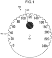
- FIG. 1 is a front view illustrating a configuration example of the dial plate 100 according to an embodiment.
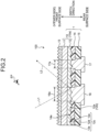
- FIG. 2 is a cross-sectional view illustrating a configuration example of the dial plate 100 according to a related example that is not claimed but is useful for understanding the invention.
- FIG. 3 is an exploded perspective view illustrating a configuration example of the dial plate 100 according to a related example that is not claimed but is useful for understanding the invention.
- FIG. 3 is a related example that is not claimed but is useful for understanding the invention, and schematically illustrates the features of the layered structure of the dial plate 100.
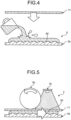
- FIG. 4 is a side view illustrating a first step of imprinting in the dial plate 100 according to the embodiment.
- FIG. 5 is a side view illustrating a second step of imprinting in the dial plate 100 according to the embodiment.
- FIG. 6 is a side view illustrating a third step of imprinting in the dial plate 100 according to the embodiment.
- the carbon decorative panel 1 is applied to the dial plate 100 as a resin decorative part having a carbon-toned pattern M.
- the dial plate 100 is applied to a vehicle indicator (not illustrated) mounted on a vehicle.
- the vehicle indicator constitutes a vehicle-mounted meter and, for example, is mounted on an instrument panel provided in the dashboard of a vehicle to display a variety of information related to the vehicle as information available for driving the vehicle.
- the dial plate 100 is, for example, a dial plate for a speedometer and formed as a circular flat plate.
- the dial plate 100 has a through hole 101 at the center, in which a not-illustrated pointer is inserted.
- the dial plate 100 has a plurality of character display sections (design display sections) 16a in the circumferential direction near the outer periphery to show the speed.
- each character display section 16a emits light radiating from a light source (not illustrated) arranged in the dial plate 100 on the opposite side to the viewer side viewed by the driver, to the viewer side. The driver then can recognize a character in the character display section 16a that shows the vehicle speed in the dial plate 100.
- FIG. 1 partially illustrates the carbon-toned pattern M
- the carbon-toned pattern M is provided, for example, in a region excluding the regions of the character display sections 16a.
- the depth direction of the dial plate 100 typically corresponds to the front-back direction of the vehicle to which the dial plate 100 is applied.
- the front surface side of the dial plate 100 is the side facing the driver's seat of the vehicle and typically the viewer side viewed by the driver sitting in the driver's seat, that is, the driver's eyepoint EP side.
- the rear surface side of the dial plate 100 is the opposite side to the front surface side in the depth direction and typically the side accommodated in the inside of the instrument panel.
- the dial plate 100 includes a carbon decorative panel 1, an anti-glare (AG) print layer 13 as a low reflection layer, a design layer 16, and a smoke layer 17.
- the carbon decorative panel 1 includes a clear decoration body 10, a carbon color layer 14, and a light-blocking print layer 15.
- FIG. 3 which is a related example that is not claimed but is useful for understanding the invention, in the dial plate 100, the AG print layer 13, the clear decoration body 10, the carbon color layer 14, and the light-blocking print layer 15 are layered in this order from the front surface side to the rear surface side in the depth direction.
- the clear decoration body 10 has a main body 10a that transmits light of wavelengths in the visible light range.
- the main body 10a includes a substrate 11 and a clear layer 12.
- the substrate 11 serves as the base of the dial plate 100.
- the substrate 11 is formed of, for example, a resin material such as acrylic resin and polycarbonate that transmits light of wavelengths in the visible light range.
- the substrate 11 is formed by shaping a resin material into a desired flat plate shape, for example, using a mold.
- the clear layer 12 has a carbon-toned pattern M.
- the clear layer 12 is provided by imprinting described later on the opposite side to the viewer side of the substrate 11, that is, on the rear surface side of the substrate 11.
- the clear layer 12 is formed of, for example, a photocurable resin material (ink) that transmits light of wavelengths in the visible light range and is cured when irradiated with ultraviolet (UV) rays.
- the clear layer 12 includes a carbon-toned irregular surface 12a.
- the carbon-toned irregular surface 12a is provided on the clear layer 12 on the opposite side to the substrate 11, and a plurality of projections and depressions 12b form the carbon-toned pattern M.
- the protrusions and depressions 12b constitute a plurality of unit patterns 12c.
- Each unit pattern 12c constitutes a weave of pseudo carbon fiber bundles presenting actual pre-impregnated carbon fiber bundles in a pseudo manner, in which each individual pseudo carbon fiber presenting an actual carbon fiber in a pseudo manner is formed.
- pre-impregnation refers to the woven actual carbon fibers impregnated with resin and cured.
- the unit pattern 12c has a top portion 12d and a pair of curved portions 12e. The top portion 12d is positioned at the center of the unit pattern 12c in the extending direction of a pseudo carbon fiber bundle.
- a pair of curved portions 12e are positioned on both sides of the top portion 12d in the extending direction of a pseudo carbon fiber bundle and are formed in a curved shape.
- the top portion 12d of the unit pattern 12c is formed in a concave shape from the opposite side to the viewer side toward the viewer side.
- the AG print layer 13 suppresses reflection of light.
- the AG print layer 13 is laminated on the viewer side of the substrate 11 and provided over the entire surface of the substrate 11.
- the AG print layer 13 is formed, for example, by screen printing on the viewer side of the substrate 11.
- the AG print layer 13 has minute protrusions and depressions on the viewer side of the substrate 11.
- the AG print layer 13 diffuses incident light L1 incident from the viewer side on the minute protrusions and depressions to suppress regular reflection of incident light L1 on the surface of the substrate 11 on the viewer side.
- the carbon color layer 14 is a colored layer colored in a carbon color.
- carbon color is, for example, black (carbon black).
- the carbon color layer 14 is laminated on the clear layer 12 on the carbon-toned irregular surface 12a side.
- the carbon color layer 14 is formed, for example, by printing ink of a resin material on the carbon-toned irregular surface 12a.
- the carbon color layer 14 is formed, for example, by screen printing.
- a screen printer prints ink colored in the carbon color on the carbon-toned irregular surface 12a.
- the screen printer prints ink, for example, in the region excluding the region of the character display section 16a and the region of an indicator display section (design display section) 17a on the carbon-toned irregular surface 12a.
- the carbon-toned pattern M thus does not appear in the region of the character display section 16a and the region of the indicator display section 17a.
- the carbon color layer 14 includes a base material of a resin material colored in the carbon color and a bright material added to the base material and does not transmit light.
- the bright material has a refractive index different from that of the resin material of the clear layer 12 and has a gloss.
- the bright material includes, for example, aluminum, silver, or pearl.
- the carbon color layer 14 has a reflective surface 14a on the carbon-toned irregular surface 12a side.
- the reflective surface 14a is provided in contact with the protrusions and depressions 12b of the carbon-toned irregular surface 12a and has the shape of the carbon-toned irregular surface 12a. That is, the reflective surface 14a has the same shape as the shape of each unit pattern 12c of the carbon-toned irregular surface 12a.
- a portion of the reflective surface 14a that is in contact with the top portion 12d of the unit pattern 12c is formed in a concave shape from the opposite side to the viewer side toward the viewer side as viewed from the viewer (eyepoint EP) side.
- a weave of pseudo carbon fiber bundles is formed as viewed from the viewer (eyepoint EP) side, and each individual pseudo carbon fiber is formed.
- the reflective surface 14a reflects incident light L1 transmitted through the clear decoration body 10 toward the viewer side as reflected light L2.
- the light-blocking print layer 15 is a light-blocking layer that blocks light.
- the light-blocking print layer 15 is laminated on the carbon color layer 14 on the opposite side to the viewer side.
- the light-blocking print layer 15 is formed, for example, by printing ink of a resin material on the carbon color layer 14.
- the light-blocking print layer 15 is formed, for example, using a screen printer.
- the screen printer prints ink colored in a light-blocking color on the rear surface side of the carbon color layer 14.
- the screen printer prints ink on the rear surface side of the carbon color layer 14, for example, in a region excluding the region of the character display section 16a and the region of the indicator display section 17a.
- the light-blocking print layer 15 blocks light incident from the opposite side (rear surface side) to the viewer side.
- the design layer 16 forms the character display section 16a.
- the character display section 16a transmits light such that a design related to the vehicle is illuminated.
- the design layer 16 is laminated on the carbon-toned irregular surface 12a side of the clear layer 12.
- the design layer 16 is formed, for example, by printing ink of a resin material in the region of the character display section 16a in the clear layer 12.
- the design layer 16 is formed, for example, using a screen printer.
- the screen printer prints translucent ink colored in a desired color in the region of the character display section 16a in the clear layer 12.
- the design layer 16 transmits light emitted from a light source (not illustrated) provided on the opposite side (rear surface side) to the viewer side and emits the transmitted light to the clear layer 12.
- the character display section 16a shows a vehicle speed in the dial plate 100 in a display manner in which the carbon-toned pattern M is not superimposed.
- the smoke layer 17 forms the indicator display section 17a.
- the indicator display section 17a transmits light such that a design related to the vehicle is illuminated.
- the smoke layer 17 is laminated on the carbon-toned irregular surface 12a side of the clear layer 12.
- the smoke layer 17 is formed, for example, by printing ink of a resin material in the region of the indicator display section 17a in the clear layer 12.
- the smoke layer 17 is formed, for example, using a screen printer.
- the screen printer prints ink colored in a light-reducing color in the region of the indicator display section 17a in the clear layer 12.
- the smoke layer 17 transmits light emitted from a light source (not illustrated) provided on the opposite side (rear surface side) to the viewer side and emits the transmitted light to the clear layer 12.
- the indicator display section 17a shows an indicator on the dial plate 100 in a display manner in which the carbon-toned pattern M is not superimposed.
- the imprinting system 2 includes a mold 2a, a roller 2b, and a UV metal-halide lamp 2c.
- the mold 2a has a plurality of protrusions and depressions 2d on its surface for forming the unit patterns 12c of the carbon-toned pattern M.
- the operator first pours a liquid photocurable resin material (ink) onto the surface of the mold 2a with the protrusions and depressions 2d.
- ink liquid photocurable resin material
- the operator then operates the imprinting system 2 to press the substrate 11 against the photocurable resin material poured on the surface of the mold 2a using the roller 2b while irradiating the photocurable resin material with UV light using the UV metal-halide lamp 2c to cure the photocurable resin material.
- the operator then operates the imprinting system 2 to move the photocurable resin material (clear layer 12) laminated on the substrate 11 away from the mold 2a.
- the clear decoration body 10 with the carbon-toned irregular surface 12a thus can be formed.
- the carbon decorative panel 1 includes the clear decoration body 10 and the carbon color layer 14.
- the clear decoration body 10 has the main body 10a transmitting light and includes the carbon-toned irregular surface 12a provided on the opposite side to the viewer side of the main body 10a and having the carbon-toned pattern M formed with the protrusions and depressions 12b.
- the carbon color layer 14 is laminated on the carbon-toned irregular surface 12a, includes the reflective surface 14a reflecting incident light L1 transmitted through the clear decoration body 10, and is colored in the carbon color.
- a clear layer having a carbon-toned pattern is provided on the viewer side of the substrate and reflects light by the difference in refractive index between the air layer and the clear layer to represent a carbon-toned pattern. Accordingly, the panel is whitish as a whole and it is difficult to ensure the texture of the carbon-toned pattern.
- the reflective surface 14a of the carbon color layer 14 that represents actual pre-impregnated carbon fiber bundles in a pseudo manner reflects incident light L1 and the reflected light L2 represents the carbon-toned pattern M.
- the carbon decorative panel 1 can represent reflected light reflected by a reflective surface of actual pre-impregnated carbon fiber bundles in a pseudo manner.
- the carbon decorative panel 1 thus can achieve the appearance that resembles an actual pre-impregnated carbon member. Accordingly, the carbon decorative panel 1 can appropriately ensure the texture of the carbon-toned pattern M.
- the reflective surface 14a is provided in contact with the protrusions and depressions 12b of the carbon-toned irregular surface 12a.
- the reflective surface 14a of the carbon decorative panel 1 has the shape equivalent to the shape of the carbon-toned irregular surface 12a. That is, the reflective surface 14a has the pattern of unit patterns 12c of the carbon-toned irregular surface 12a. That is, in the reflective surface 14a, a weave of pseudo carbon fiber bundles is formed as viewed from the viewer (eyepoint EP) side, and each individual pseudo carbon fiber is formed.
- the carbon decorative panel 1 thus can achieve the appearance that resembles an actual pre-impregnated carbon member.
- the main body 10a of the clear decoration body 10 includes the substrate 11 transmitting light and the clear layer 12 laminated on the surface of the substrate 11 on the opposite side to the viewer side and having the carbon-toned irregular surface 12a.
- the carbon decorative panel 1 can be formed with the substrate 11 and the clear layer 12 as separate components.
- the clear layer 12 is formed of a photocurable resin material that is cured when irradiated with light.
- the carbon decorative panel 1 can be formed by imprinting.
- the main body 10a of the clear decoration body 10 is formed of a resin material that transmits light.
- the carbon color layer 14 includes a base material colored in the carbon color and a bright material added to the base material and having a refractive index different from that of the resin material and a gloss. With this configuration, the carbon decorative panel 1 can appropriately reflect incident light L1 on the reflective surface 14a of the carbon color layer 14 by the difference in refractive index between the clear decoration body 10 and the carbon color layer 14.
- the dial plate 100 includes the clear decoration body 10, the carbon color layer 14, the AG print layer 13, the character display section 16a (design layer 16), and the indicator display section 17a (smoke layer 17).
- the clear decoration body 10 has the main body 10a provided on the vehicle and transmitting light.
- the clear decoration body 10 includes the carbon-toned irregular surface 12a provided on the opposite side to the viewer side of the main body 10a and having the carbon-toned pattern M formed with the protrusions and depressions 12b.
- the carbon color layer 14 is laminated on the carbon-toned irregular surface 12a, includes the reflective surface 14a reflecting light transmitted through the clear decoration body 10, and is colored in the carbon color.
- the AG print layer 13 is laminated on the viewer side of the main body 10a and suppresses reflection of light.
- the character display section 16a and the indicator display section 17a are provided on the main body 10a and transmits light such that a design related to the vehicle is illuminated. With this configuration, the dial plate 100 achieves the similar effects as the carbon decorative panel 1 described
- FIG. 7 is a cross-sectional view illustrating the invention, namely a dial plate 100A.
- the carbon color layer 14 is laminated in a region excluding the region of the character display section 16a and the region of the indicator display section 17a, so that the carbon-toned pattern M does not appear in the regions of the character display section 16a and the indicator display section 17a.
- the carbon color layer 14A is laminated also in the region of the character display section 16a and the region of the indicator display section 17a, so that the carbon-toned pattern M appears also in the regions of the character display section 16a and the indicator display section 17a.
- the components equivalent to those of the dial plate 100 according to the embodiment are denoted by the same reference signs and a detailed description thereof is omitted.
- the dial plate 100A includes a carbon decorative panel 1A, an AG print layer 13, a design layer 16, and a smoke layer 17.
- the carbon decorative panel 1A includes a clear decoration body 10, a carbon color layer 14A, a carbon color layer 18, and a light-blocking print layer 15.
- the carbon color layer 14A includes a base material of a resin material colored in the carbon color and a bright material added to the base material and is translucent.
- the carbon color layer 14A is printed on the entire carbon-toned irregular surface 12a of the clear layer 12 in the clear decoration body 10.
- the carbon color layer 14A has a reflective surface 14a on the carbon-toned irregular surface 12a side.
- the reflective surface 14a reflects incident light L1 transmitted through the clear decoration body 10 toward the viewer side as reflected light L2.
- the carbon color layer 18 is a colored layer colored in the carbon color.
- the carbon color layer 18 is laminated on the rear surface side of the carbon color layer 14A.
- the carbon color layer 18 is formed, for example, by printing ink of a resin material on the rear surface side of the carbon color layer 14A.
- the carbon color layer 18 is formed, for example, by screen printing.
- a screen printer prints, for example, ink colored in the carbon color on the rear surface side of the carbon color layer 14A.
- the screen printer prints ink on the rear surface side of the carbon color layer 14A, for example, in a region excluding the region of the character display section 16a and the region of the indicator display section 17a.
- the carbon color layer 18 preferably includes a base material of a resin material colored in the carbon color and a bright material added to the base material.
- the bright material is not necessarily included in the base material.
- the light-blocking print layer 15 is laminated on the carbon color layer 18 on the opposite side to the viewer side.
- the design layer 16 is laminated on the rear surface side of the carbon color layer 14A in the region of the character display section 16a.
- the design layer 16 transmits light emitted from a light source provided on the opposite side (rear surface side) to the viewer side and emits the transmitted light to the carbon color layer 14A.
- the character display section 16a shows a vehicle speed in the dial plate 100 in a display manner in which the carbon-toned pattern M is superimposed.
- the smoke layer 17 is laminated on the rear surface side of the carbon color layer 14A in the region of the indicator display section 17a.
- the smoke layer 17 transmits light emitted from a light source provided on the opposite side (rear surface side) to the viewer side and emits the transmitted light to the carbon color layer 14A.
- the indicator display section 17a shows an indicator in the dial plate 100 in a display manner in which the carbon-toned pattern M is superimposed. In this way, the dial plate 100A according to the first modification can display a vehicle speed and an indicator in the dial plate 100 in a display manner in which the carbon-toned pattern M is superimposed.
- FIG. 8 is a cross-sectional view illustrating a configuration example of a dial plate 100B according a related example that is not claimed but is useful for understanding the invention.
- a carbon decorative panel 1B according a related example that is not claimed but is useful for understanding the invention differs from the carbon decorative panel 1 according to the embodiment in that a carbon-toned irregular surface 12a of a clear layer 12B is formed to be convex from the viewer side toward the opposite side to the viewer side.
- the components equivalent to those of the carbon decorative panel 1 according to the embodiment are denoted by the same reference signs and a detailed description thereof is omitted.
- the carbon decorative panel 1B includes a clear decoration body 10B, a carbon color layer 14, and a light-blocking print layer 15.
- the clear decoration body 10B has a substrate 11 and a clear layer 12B.
- the clear layer 12B has a carbon-toned pattern M.
- the clear layer 12B is provided on the rear surface side of the substrate 11 by imprinting.
- the clear layer 12B is formed of a photocurable resin material (ink) that transmits light of wavelengths in the visible light range and is cured when irradiated with UV light.
- the clear layer 12B includes a carbon-toned irregular surface 12a.
- the carbon-toned irregular surface 12a is provided on the clear layer 12B on the opposite side to the substrate 11 and has the carbon-toned pattern M formed with a plurality of protrusions and depressions.
- the protrusions and depressions form a plurality of unit patterns 12v.
- Each unit pattern 12v constitutes a weave of pseudo carbon fiber bundles presenting actual pre-impregnated carbon fiber bundles in a pseudo manner, in which each individual pseudo carbon fiber presenting an actual carbon fiber in a pseudo manner is formed.
- the unit pattern 12v has a top portion 12u and a pair of curved portions 12t.
- the top portion 12u of the unit pattern 12v is formed to be convex from the viewer side toward the opposite side to the viewer side.
- the carbon color layer 14 has a reflective surface 14a on the carbon-toned irregular surface 12a side.
- the reflective surface 14a is provided in contact with the protrusions and depressions 12b of the carbon-toned irregular surface 12a and has the shape of the carbon-toned irregular surface 12a. That is, the reflective surface 14a has the same shape as the shape of each unit pattern 12v of the carbon-toned irregular surface 12a.
- a weave of pseudo carbon fiber bundles is formed as viewed from the viewer (eyepoint EP) side, and each individual pseudo carbon fiber is formed.
- the reflective surface 14a reflects incident light L1 transmitted through the clear decoration body 10B toward the viewer side as reflected light L2.
- the carbon decorative panel 1B according to the second modification includes the clear decoration body 10B and the carbon color layer 14.
- the clear decoration body 10B has the main body 10a transmitting light and includes the carbon-toned irregular surface 12a provided on the opposite side of the main body 10a to the viewer side and having the carbon-toned pattern M formed with the protrusions and depressions 12b.
- the carbon color layer 14 is laminated on the carbon-toned irregular surface 12a, includes the reflective surface 14a reflecting incident light L1 transmitted through the clear decoration body 10B, and is colored in the carbon color.
- the carbon decorative panel 1B can represent reflected light reflected by a reflective surface of actual pre-impregnated carbon fiber bundles in a pseudo manner.
- the carbon decorative panel 1B thus can achieve the appearance that resembles an actual pre-impregnated carbon member. Accordingly, the carbon decorative panel 1B can appropriately ensure the texture of the carbon-toned pattern M.
- the carbon decorative panel 1 (1A) is applied to the dial plate 100 (100A) as a decorative part having the carbon-toned pattern M.
- embodiments are not limited thereto and may be applied to a decorative sheet for an instrument panel.
- the dial plate 100 (100A) described above includes the carbon decorative panel 1 (1A), the AG print layer 13, the design layer 16, and the smoke layer 17.
- embodiments are not limited thereto and may have any other configuration.
- the main body 10a of the clear decoration body 10 described above includes the substrate 11 and the clear layer 12 formed as separated components by imprinting. However, embodiments are not limited thereto.
- the main body 10a of the clear decoration body 10 may be formed, for example, such that the substrate 11 and the clear layer 12 are integrally formed by resin injection molding.
- the clear layer 12 described above is formed on the substrate 11 by UV-curing imprinting.
- UV-curing imprinting may be used.
- the dial plate 100 (100A) described above includes the AG print layer 13 as a low reflection layer.
- a member other than the AG print layer 13 may be used to form a low reflection layer.
- the AG print layer 13, the carbon color layer 14, the light-blocking print layer 15, the design layer 16, and the smoke layer 17 are formed using a screen printer in the example above. However, embodiments are not limited thereto. For example, they may be formed using an inkjet printer.
- the carbon-toned irregular surface 12a of the clear layer 12 may be formed to be convex from the viewer side toward the opposite side to the viewer side.
- the resin decorative part and the dial plate according to the present embodiment include the clear decoration body including the carbon-toned irregular surface provided on the opposite side to the viewer side and the carbon color layer laminated on the carbon-toned irregular surface. This configuration enables light to be reflected by the reflective surface of the carbon color layer and appropriately ensures the texture of the carbon-toned decoration.
Landscapes
- Engineering & Computer Science (AREA)
- Mechanical Engineering (AREA)
- Chemical & Material Sciences (AREA)
- Combustion & Propulsion (AREA)
- Transportation (AREA)
- Physics & Mathematics (AREA)
- General Physics & Mathematics (AREA)
- Instrument Panels (AREA)
- Details Of Measuring Devices (AREA)
- Laminated Bodies (AREA)
Description
- The present invention relates to a resin decorative part and a dial plate.
- Conventionally,
JP 2017 - 102 016 A - It has been desired, for example, to further improve the texture of the carbon-toned decoration in the instrument dial disclosed in
JP 2017 - 102 016 A JP 2008 - 134 164 A -
WO 2012 / 020 706 A1 describes a dial plate having a hairline-shaped uneven section which is provided by grinding the rear surface of a transparent base plate with a grindstone. A mirror ink layer is provided on said uneven rear surface to reflect external light incident from the front side of the transparent base plate. - It is an object of the present invention to provide a resin decorative part and a dial plate that can appropriately ensure the texture of the carbon-toned decoration. According the present invention said object is solved by a resin decorative part having the features of the
independent claim 1. Preferred embodiments are laid down in the dependent claims. - The above and other objects, features, advantages and technical and industrial significance of this invention will be better understood by reading the following detailed description of presently preferred embodiments of the invention, when considered in connection with the accompanying drawings.
-
-
FIG. 1 is a front view illustrating a configuration example of a dial plate according to an embodiment; -
FIG. 2 is a cross-sectional view illustrating a configuration example of the dial plate according a related example that is not claimed but is useful for understanding the invention; -
FIG. 3 is an exploded perspective view illustrating a configuration example of the dial plate according a related example that is not claimed but is useful for understanding the invention; -
FIG. 4 is a side view illustrating a first step of imprinting in the dial plate according to the embodiment; -
FIG. 5 is a side view illustrating a second step of imprinting in the dial plate according to the embodiment; -
FIG. 6 is a side view illustrating a third step of imprinting in the dial plate according to the embodiment; -
FIG. 7 is a cross-sectional view illustrating a configuration example of the dial plate according the invention; and -
FIG. 8 is a cross-sectional view illustrating a configuration example of the dial plate according a related example that is not claimed but is useful for understanding the invention. - Modes for carrying out the present invention (embodiments) will be described in detail with reference to the drawings. The present invention is not limited by the description of embodiments below.
- A carbon decorative panel (resin decorative part) 1 and a
dial plate 100 according to an embodiment will be described.FIG. 1 is a front view illustrating a configuration example of thedial plate 100 according to an embodiment.FIG. 2 is a cross-sectional view illustrating a configuration example of thedial plate 100 according to a related example that is not claimed but is useful for understanding the invention.FIG. 3 is an exploded perspective view illustrating a configuration example of thedial plate 100 according to a related example that is not claimed but is useful for understanding the invention.FIG. 3 , is a related example that is not claimed but is useful for understanding the invention, and schematically illustrates the features of the layered structure of thedial plate 100.FIG. 4 is a side view illustrating a first step of imprinting in thedial plate 100 according to the embodiment.FIG. 5 is a side view illustrating a second step of imprinting in thedial plate 100 according to the embodiment.FIG. 6 is a side view illustrating a third step of imprinting in thedial plate 100 according to the embodiment. - As illustrated in
FIG. 1 , the carbondecorative panel 1 is applied to thedial plate 100 as a resin decorative part having a carbon-toned pattern M. Thedial plate 100 is applied to a vehicle indicator (not illustrated) mounted on a vehicle. The vehicle indicator constitutes a vehicle-mounted meter and, for example, is mounted on an instrument panel provided in the dashboard of a vehicle to display a variety of information related to the vehicle as information available for driving the vehicle. - The
dial plate 100 is, for example, a dial plate for a speedometer and formed as a circular flat plate. Thedial plate 100 has a throughhole 101 at the center, in which a not-illustrated pointer is inserted. Thedial plate 100 has a plurality of character display sections (design display sections) 16a in the circumferential direction near the outer periphery to show the speed. For example, eachcharacter display section 16a emits light radiating from a light source (not illustrated) arranged in thedial plate 100 on the opposite side to the viewer side viewed by the driver, to the viewer side. The driver then can recognize a character in thecharacter display section 16a that shows the vehicle speed in thedial plate 100. AlthoughFIG. 1 partially illustrates the carbon-toned pattern M, the carbon-toned pattern M is provided, for example, in a region excluding the regions of thecharacter display sections 16a. - As used herein the depth direction of the
dial plate 100 typically corresponds to the front-back direction of the vehicle to which thedial plate 100 is applied. The front surface side of thedial plate 100 is the side facing the driver's seat of the vehicle and typically the viewer side viewed by the driver sitting in the driver's seat, that is, the driver's eyepoint EP side. By contrast, the rear surface side of thedial plate 100 is the opposite side to the front surface side in the depth direction and typically the side accommodated in the inside of the instrument panel. - As illustrated in
FIG. 2 , which is a related example that is not claimed but is useful for understanding the invention, thedial plate 100 includes a carbondecorative panel 1, an anti-glare (AG)print layer 13 as a low reflection layer, adesign layer 16, and asmoke layer 17. The carbondecorative panel 1 includes aclear decoration body 10, acarbon color layer 14, and a light-blockingprint layer 15. As illustrated inFIG. 3 , which is a related example that is not claimed but is useful for understanding the invention, in thedial plate 100, theAG print layer 13, theclear decoration body 10, thecarbon color layer 14, and the light-blockingprint layer 15 are layered in this order from the front surface side to the rear surface side in the depth direction. - The
clear decoration body 10 has amain body 10a that transmits light of wavelengths in the visible light range. Themain body 10a includes asubstrate 11 and aclear layer 12. Thesubstrate 11 serves as the base of thedial plate 100. Thesubstrate 11 is formed of, for example, a resin material such as acrylic resin and polycarbonate that transmits light of wavelengths in the visible light range. Thesubstrate 11 is formed by shaping a resin material into a desired flat plate shape, for example, using a mold. - The
clear layer 12 has a carbon-toned pattern M. Theclear layer 12 is provided by imprinting described later on the opposite side to the viewer side of thesubstrate 11, that is, on the rear surface side of thesubstrate 11. Theclear layer 12 is formed of, for example, a photocurable resin material (ink) that transmits light of wavelengths in the visible light range and is cured when irradiated with ultraviolet (UV) rays. As illustrated inFIG. 2 , which is a related example that is not claimed but is useful for understanding the invention, theclear layer 12 includes a carbon-tonedirregular surface 12a. The carbon-tonedirregular surface 12a is provided on theclear layer 12 on the opposite side to thesubstrate 11, and a plurality of projections anddepressions 12b form the carbon-toned pattern M. The protrusions anddepressions 12b constitute a plurality ofunit patterns 12c. Eachunit pattern 12c constitutes a weave of pseudo carbon fiber bundles presenting actual pre-impregnated carbon fiber bundles in a pseudo manner, in which each individual pseudo carbon fiber presenting an actual carbon fiber in a pseudo manner is formed. As used herein pre-impregnation refers to the woven actual carbon fibers impregnated with resin and cured. Theunit pattern 12c has atop portion 12d and a pair ofcurved portions 12e. Thetop portion 12d is positioned at the center of theunit pattern 12c in the extending direction of a pseudo carbon fiber bundle. A pair ofcurved portions 12e are positioned on both sides of thetop portion 12d in the extending direction of a pseudo carbon fiber bundle and are formed in a curved shape. Thetop portion 12d of theunit pattern 12c is formed in a concave shape from the opposite side to the viewer side toward the viewer side. - The
AG print layer 13 suppresses reflection of light. TheAG print layer 13 is laminated on the viewer side of thesubstrate 11 and provided over the entire surface of thesubstrate 11. TheAG print layer 13 is formed, for example, by screen printing on the viewer side of thesubstrate 11. TheAG print layer 13 has minute protrusions and depressions on the viewer side of thesubstrate 11. TheAG print layer 13 diffuses incident light L1 incident from the viewer side on the minute protrusions and depressions to suppress regular reflection of incident light L1 on the surface of thesubstrate 11 on the viewer side. - The
carbon color layer 14 is a colored layer colored in a carbon color. As used herein carbon color is, for example, black (carbon black). Thecarbon color layer 14 is laminated on theclear layer 12 on the carbon-tonedirregular surface 12a side. Thecarbon color layer 14 is formed, for example, by printing ink of a resin material on the carbon-tonedirregular surface 12a. Thecarbon color layer 14 is formed, for example, by screen printing. For example, a screen printer prints ink colored in the carbon color on the carbon-tonedirregular surface 12a. The screen printer prints ink, for example, in the region excluding the region of thecharacter display section 16a and the region of an indicator display section (design display section) 17a on the carbon-tonedirregular surface 12a. The carbon-toned pattern M thus does not appear in the region of thecharacter display section 16a and the region of theindicator display section 17a. - The
carbon color layer 14 includes a base material of a resin material colored in the carbon color and a bright material added to the base material and does not transmit light. The bright material has a refractive index different from that of the resin material of theclear layer 12 and has a gloss. The bright material includes, for example, aluminum, silver, or pearl. Thecarbon color layer 14 has areflective surface 14a on the carbon-tonedirregular surface 12a side. Thereflective surface 14a is provided in contact with the protrusions anddepressions 12b of the carbon-tonedirregular surface 12a and has the shape of the carbon-tonedirregular surface 12a. That is, thereflective surface 14a has the same shape as the shape of eachunit pattern 12c of the carbon-tonedirregular surface 12a. Specifically, a portion of thereflective surface 14a that is in contact with thetop portion 12d of theunit pattern 12c is formed in a concave shape from the opposite side to the viewer side toward the viewer side as viewed from the viewer (eyepoint EP) side. In this way, in thereflective surface 14a, a weave of pseudo carbon fiber bundles is formed as viewed from the viewer (eyepoint EP) side, and each individual pseudo carbon fiber is formed. Thereflective surface 14a reflects incident light L1 transmitted through theclear decoration body 10 toward the viewer side as reflected light L2. - The light-blocking
print layer 15 is a light-blocking layer that blocks light. The light-blockingprint layer 15 is laminated on thecarbon color layer 14 on the opposite side to the viewer side. The light-blockingprint layer 15 is formed, for example, by printing ink of a resin material on thecarbon color layer 14. The light-blockingprint layer 15 is formed, for example, using a screen printer. The screen printer prints ink colored in a light-blocking color on the rear surface side of thecarbon color layer 14. The screen printer prints ink on the rear surface side of thecarbon color layer 14, for example, in a region excluding the region of thecharacter display section 16a and the region of theindicator display section 17a. The light-blockingprint layer 15 blocks light incident from the opposite side (rear surface side) to the viewer side. - The
design layer 16 forms thecharacter display section 16a. Thecharacter display section 16a transmits light such that a design related to the vehicle is illuminated. Thedesign layer 16 is laminated on the carbon-tonedirregular surface 12a side of theclear layer 12. Thedesign layer 16 is formed, for example, by printing ink of a resin material in the region of thecharacter display section 16a in theclear layer 12. Thedesign layer 16 is formed, for example, using a screen printer. The screen printer prints translucent ink colored in a desired color in the region of thecharacter display section 16a in theclear layer 12. Thedesign layer 16 transmits light emitted from a light source (not illustrated) provided on the opposite side (rear surface side) to the viewer side and emits the transmitted light to theclear layer 12. Thecharacter display section 16a shows a vehicle speed in thedial plate 100 in a display manner in which the carbon-toned pattern M is not superimposed. - The
smoke layer 17 forms theindicator display section 17a. Theindicator display section 17a transmits light such that a design related to the vehicle is illuminated. Thesmoke layer 17 is laminated on the carbon-tonedirregular surface 12a side of theclear layer 12. Thesmoke layer 17 is formed, for example, by printing ink of a resin material in the region of theindicator display section 17a in theclear layer 12. Thesmoke layer 17 is formed, for example, using a screen printer. The screen printer prints ink colored in a light-reducing color in the region of theindicator display section 17a in theclear layer 12. Thesmoke layer 17 transmits light emitted from a light source (not illustrated) provided on the opposite side (rear surface side) to the viewer side and emits the transmitted light to theclear layer 12. Theindicator display section 17a shows an indicator on thedial plate 100 in a display manner in which the carbon-toned pattern M is not superimposed. - Referring now to
FIG. 4 to FIG. 6 , the steps of imprinting in thedial plate 100 are described. The operator performs imprinting using animprinting system 2. Theimprinting system 2 includes amold 2a, aroller 2b, and a UV metal-halide lamp 2c. Themold 2a has a plurality of protrusions anddepressions 2d on its surface for forming theunit patterns 12c of the carbon-toned pattern M. As illustrated inFIG. 4 , the operator first pours a liquid photocurable resin material (ink) onto the surface of themold 2a with the protrusions anddepressions 2d. As illustrated inFIG. 5 , the operator then operates theimprinting system 2 to press thesubstrate 11 against the photocurable resin material poured on the surface of themold 2a using theroller 2b while irradiating the photocurable resin material with UV light using the UV metal-halide lamp 2c to cure the photocurable resin material. As illustrated inFIG. 6 , the operator then operates theimprinting system 2 to move the photocurable resin material (clear layer 12) laminated on thesubstrate 11 away from themold 2a. Theclear decoration body 10 with the carbon-tonedirregular surface 12a thus can be formed. - As described above, the carbon
decorative panel 1 according to the embodiment includes theclear decoration body 10 and thecarbon color layer 14. Theclear decoration body 10 has themain body 10a transmitting light and includes the carbon-tonedirregular surface 12a provided on the opposite side to the viewer side of themain body 10a and having the carbon-toned pattern M formed with the protrusions anddepressions 12b. Thecarbon color layer 14 is laminated on the carbon-tonedirregular surface 12a, includes thereflective surface 14a reflecting incident light L1 transmitted through theclear decoration body 10, and is colored in the carbon color. - In the conventional carbon decorative panel, for example, a clear layer having a carbon-toned pattern is provided on the viewer side of the substrate and reflects light by the difference in refractive index between the air layer and the clear layer to represent a carbon-toned pattern. Accordingly, the panel is whitish as a whole and it is difficult to ensure the texture of the carbon-toned pattern. By contrast, in the carbon
decorative panel 1 according to the embodiment, thereflective surface 14a of thecarbon color layer 14 that represents actual pre-impregnated carbon fiber bundles in a pseudo manner reflects incident light L1 and the reflected light L2 represents the carbon-toned pattern M. With this configuration, the carbondecorative panel 1 can represent reflected light reflected by a reflective surface of actual pre-impregnated carbon fiber bundles in a pseudo manner. The carbondecorative panel 1 thus can achieve the appearance that resembles an actual pre-impregnated carbon member. Accordingly, the carbondecorative panel 1 can appropriately ensure the texture of the carbon-toned pattern M. - In the above-described carbon
decorative panel 1, thereflective surface 14a is provided in contact with the protrusions anddepressions 12b of the carbon-tonedirregular surface 12a. With this configuration, thereflective surface 14a of the carbondecorative panel 1 has the shape equivalent to the shape of the carbon-tonedirregular surface 12a. That is, thereflective surface 14a has the pattern ofunit patterns 12c of the carbon-tonedirregular surface 12a. That is, in thereflective surface 14a, a weave of pseudo carbon fiber bundles is formed as viewed from the viewer (eyepoint EP) side, and each individual pseudo carbon fiber is formed. The carbondecorative panel 1 thus can achieve the appearance that resembles an actual pre-impregnated carbon member. - In the above-described carbon
decorative panel 1, themain body 10a of theclear decoration body 10 includes thesubstrate 11 transmitting light and theclear layer 12 laminated on the surface of thesubstrate 11 on the opposite side to the viewer side and having the carbon-tonedirregular surface 12a. In this way, the carbondecorative panel 1 can be formed with thesubstrate 11 and theclear layer 12 as separate components. - In the above-described carbon
decorative panel 1, theclear layer 12 is formed of a photocurable resin material that is cured when irradiated with light. In this configuration, the carbondecorative panel 1 can be formed by imprinting. - In the above-described carbon
decorative panel 1, themain body 10a of theclear decoration body 10 is formed of a resin material that transmits light. Thecarbon color layer 14 includes a base material colored in the carbon color and a bright material added to the base material and having a refractive index different from that of the resin material and a gloss. With this configuration, the carbondecorative panel 1 can appropriately reflect incident light L1 on thereflective surface 14a of thecarbon color layer 14 by the difference in refractive index between theclear decoration body 10 and thecarbon color layer 14. - The
dial plate 100 according to the embodiment includes theclear decoration body 10, thecarbon color layer 14, theAG print layer 13, thecharacter display section 16a (design layer 16), and theindicator display section 17a (smoke layer 17). Theclear decoration body 10 has themain body 10a provided on the vehicle and transmitting light. Theclear decoration body 10 includes the carbon-tonedirregular surface 12a provided on the opposite side to the viewer side of themain body 10a and having the carbon-toned pattern M formed with the protrusions anddepressions 12b. Thecarbon color layer 14 is laminated on the carbon-tonedirregular surface 12a, includes thereflective surface 14a reflecting light transmitted through theclear decoration body 10, and is colored in the carbon color. TheAG print layer 13 is laminated on the viewer side of themain body 10a and suppresses reflection of light. Thecharacter display section 16a and theindicator display section 17a are provided on themain body 10a and transmits light such that a design related to the vehicle is illuminated. With this configuration, thedial plate 100 achieves the similar effects as the carbondecorative panel 1 described above. - A first modification of the embodiment will now be described.
FIG. 7 is a cross-sectional view illustrating the invention, namely adial plate 100A. In thedial plate 100 according to the embodiment, thecarbon color layer 14 is laminated in a region excluding the region of thecharacter display section 16a and the region of theindicator display section 17a, so that the carbon-toned pattern M does not appear in the regions of thecharacter display section 16a and theindicator display section 17a. In thedial plate 100A according to the first modification, thecarbon color layer 14A is laminated also in the region of thecharacter display section 16a and the region of theindicator display section 17a, so that the carbon-toned pattern M appears also in the regions of thecharacter display section 16a and theindicator display section 17a. In thedial plate 100A according to the first modification, the components equivalent to those of thedial plate 100 according to the embodiment are denoted by the same reference signs and a detailed description thereof is omitted. - As illustrated in
FIG. 7 , thedial plate 100A according the invention includes a carbondecorative panel 1A, anAG print layer 13, adesign layer 16, and asmoke layer 17. The carbondecorative panel 1A includes aclear decoration body 10, acarbon color layer 14A, acarbon color layer 18, and a light-blockingprint layer 15. Thecarbon color layer 14A includes a base material of a resin material colored in the carbon color and a bright material added to the base material and is translucent. Thecarbon color layer 14A is printed on the entire carbon-tonedirregular surface 12a of theclear layer 12 in theclear decoration body 10. Thecarbon color layer 14A has areflective surface 14a on the carbon-tonedirregular surface 12a side. Thereflective surface 14a reflects incident light L1 transmitted through theclear decoration body 10 toward the viewer side as reflected light L2. - The
carbon color layer 18 is a colored layer colored in the carbon color. Thecarbon color layer 18 is laminated on the rear surface side of thecarbon color layer 14A. Thecarbon color layer 18 is formed, for example, by printing ink of a resin material on the rear surface side of thecarbon color layer 14A. Thecarbon color layer 18 is formed, for example, by screen printing. A screen printer prints, for example, ink colored in the carbon color on the rear surface side of thecarbon color layer 14A. The screen printer prints ink on the rear surface side of thecarbon color layer 14A, for example, in a region excluding the region of thecharacter display section 16a and the region of theindicator display section 17a. Thecarbon color layer 18 preferably includes a base material of a resin material colored in the carbon color and a bright material added to the base material. However, the bright material is not necessarily included in the base material. The light-blockingprint layer 15 is laminated on thecarbon color layer 18 on the opposite side to the viewer side. - The
design layer 16 is laminated on the rear surface side of thecarbon color layer 14A in the region of thecharacter display section 16a. Thedesign layer 16 transmits light emitted from a light source provided on the opposite side (rear surface side) to the viewer side and emits the transmitted light to thecarbon color layer 14A. Thecharacter display section 16a shows a vehicle speed in thedial plate 100 in a display manner in which the carbon-toned pattern M is superimposed. - The
smoke layer 17 is laminated on the rear surface side of thecarbon color layer 14A in the region of theindicator display section 17a. Thesmoke layer 17 transmits light emitted from a light source provided on the opposite side (rear surface side) to the viewer side and emits the transmitted light to thecarbon color layer 14A. Theindicator display section 17a shows an indicator in thedial plate 100 in a display manner in which the carbon-toned pattern M is superimposed. In this way, thedial plate 100A according to the first modification can display a vehicle speed and an indicator in thedial plate 100 in a display manner in which the carbon-toned pattern M is superimposed. - A second modification of the embodiment will now be described.
FIG. 8 is a cross-sectional view illustrating a configuration example of adial plate 100B according a related example that is not claimed but is useful for understanding the invention. As illustrated inFIG. 8 , a carbondecorative panel 1B according a related example that is not claimed but is useful for understanding the invention, differs from the carbondecorative panel 1 according to the embodiment in that a carbon-tonedirregular surface 12a of aclear layer 12B is formed to be convex from the viewer side toward the opposite side to the viewer side. In the carbondecorative panel 1B according to the second modification, the components equivalent to those of the carbondecorative panel 1 according to the embodiment are denoted by the same reference signs and a detailed description thereof is omitted. - The carbon
decorative panel 1B includes aclear decoration body 10B, acarbon color layer 14, and a light-blockingprint layer 15. Theclear decoration body 10B has asubstrate 11 and aclear layer 12B. - The
clear layer 12B has a carbon-toned pattern M. Theclear layer 12B is provided on the rear surface side of thesubstrate 11 by imprinting. For example, theclear layer 12B is formed of a photocurable resin material (ink) that transmits light of wavelengths in the visible light range and is cured when irradiated with UV light. Theclear layer 12B includes a carbon-tonedirregular surface 12a. The carbon-tonedirregular surface 12a is provided on theclear layer 12B on the opposite side to thesubstrate 11 and has the carbon-toned pattern M formed with a plurality of protrusions and depressions. The protrusions and depressions form a plurality ofunit patterns 12v. Eachunit pattern 12v constitutes a weave of pseudo carbon fiber bundles presenting actual pre-impregnated carbon fiber bundles in a pseudo manner, in which each individual pseudo carbon fiber presenting an actual carbon fiber in a pseudo manner is formed. Theunit pattern 12v has atop portion 12u and a pair ofcurved portions 12t. Thetop portion 12u of theunit pattern 12v is formed to be convex from the viewer side toward the opposite side to the viewer side. - The
carbon color layer 14 has areflective surface 14a on the carbon-tonedirregular surface 12a side. Thereflective surface 14a is provided in contact with the protrusions anddepressions 12b of the carbon-tonedirregular surface 12a and has the shape of the carbon-tonedirregular surface 12a. That is, thereflective surface 14a has the same shape as the shape of eachunit pattern 12v of the carbon-tonedirregular surface 12a. In thereflective surface 14a, a weave of pseudo carbon fiber bundles is formed as viewed from the viewer (eyepoint EP) side, and each individual pseudo carbon fiber is formed. Thereflective surface 14a reflects incident light L1 transmitted through theclear decoration body 10B toward the viewer side as reflected light L2. - As described above, the carbon
decorative panel 1B according to the second modification includes theclear decoration body 10B and thecarbon color layer 14. Theclear decoration body 10B has themain body 10a transmitting light and includes the carbon-tonedirregular surface 12a provided on the opposite side of themain body 10a to the viewer side and having the carbon-toned pattern M formed with the protrusions anddepressions 12b. Thecarbon color layer 14 is laminated on the carbon-tonedirregular surface 12a, includes thereflective surface 14a reflecting incident light L1 transmitted through theclear decoration body 10B, and is colored in the carbon color. - With this configuration, the carbon
decorative panel 1B can represent reflected light reflected by a reflective surface of actual pre-impregnated carbon fiber bundles in a pseudo manner. The carbondecorative panel 1B thus can achieve the appearance that resembles an actual pre-impregnated carbon member. Accordingly, the carbondecorative panel 1B can appropriately ensure the texture of the carbon-toned pattern M. - In the foregoing description, the carbon decorative panel 1 (1A) is applied to the dial plate 100 (100A) as a decorative part having the carbon-toned pattern M. However, embodiments are not limited thereto and may be applied to a decorative sheet for an instrument panel.
- The dial plate 100 (100A) described above includes the carbon decorative panel 1 (1A), the
AG print layer 13, thedesign layer 16, and thesmoke layer 17. However, embodiments are not limited thereto and may have any other configuration. - The
main body 10a of theclear decoration body 10 described above includes thesubstrate 11 and theclear layer 12 formed as separated components by imprinting. However, embodiments are not limited thereto. Themain body 10a of theclear decoration body 10 may be formed, for example, such that thesubstrate 11 and theclear layer 12 are integrally formed by resin injection molding. - The
clear layer 12 described above is formed on thesubstrate 11 by UV-curing imprinting. However, embodiments are not limited thereto. For example, thermal-curing imprinting may be used. - The dial plate 100 (100A) described above includes the
AG print layer 13 as a low reflection layer. However, a member other than theAG print layer 13 may be used to form a low reflection layer. - The
AG print layer 13, thecarbon color layer 14, the light-blockingprint layer 15, thedesign layer 16, and thesmoke layer 17 are formed using a screen printer in the example above. However, embodiments are not limited thereto. For example, they may be formed using an inkjet printer. - In the
dial plate 100A, the carbon-tonedirregular surface 12a of theclear layer 12 may be formed to be convex from the viewer side toward the opposite side to the viewer side. - The resin decorative part and the dial plate according to the present embodiment include the clear decoration body including the carbon-toned irregular surface provided on the opposite side to the viewer side and the carbon color layer laminated on the carbon-toned irregular surface. This configuration enables light to be reflected by the reflective surface of the carbon color layer and appropriately ensures the texture of the carbon-toned decoration.
Claims (5)
- A resin decorative part (1, 1A) comprising:a clear decoration body (10) having a main body (10a) transmitting light and including a substrate (11) transmitting light and a clear layer (12), the clear layer (12) including an irregular surface (12a) disposed on an opposite side to a viewer side of the substrate (11) and having a pattern (M) formed with protrusions and depressions (12b); anda first carbon color layer (14A) that is printed on the entire irregular surface (12a) of the clear layer (12) in the clear decoration body (10), includes a first reflective surface (14a) reflecting light transmitted through the clear decoration body (10), is colored in a carbon color, and transmits light;a second carbon color layer (18) that is laminated in a region excluding a region of a design display section (16a, 17a) on a surface of opposite side to the clear decoration body (10) on the first carbon color layer (14A), is colored in a carbon color, anda light-blocking print layer (15) that is laminated on the second carbon color layer (18) on an opposite side to the viewer side,whereinthe main body (10a) is formed of a resin material transmitting light, andthe second carbon color layer (18) includes:the protrusions and depressions (12b) constitute a plurality of unit patterns (12c), and each unit pattern (12c) constitutes a weave of pseudo carbon fiber bundles.a base material of a resin material colored in a carbon color; anda bright material added to the base material, wherein
- The resin decorative part (1, 1A) according to claim 1, wherein
the first reflective surface (14a) is in contact with the protrusions and depressions (12b) of the irregular surface (12a). - The resin decorative part (1, 1A) according to claim 1, wherein
the clear layer (12) is laminated on a surface of the substrate (11) on an opposite side to the viewer side. - The resin decorative part (1, 1A) according to claim 3, wherein
the clear layer (12) is formed of a photocurable resin material that is cured when irradiated with light. - A dial plate (100, 100A) comprising:
a resin decorative part (1, 1A) according to claim 1 disposed in a vehicle and wherein the dial plate (100, 100A) further comprises:a low reflection layer (13) laminated on the viewer side of the main body (10a) to suppress reflection of light; anda design display section (16a, 17a) disposed on the main body (10a) and transmitting light such that a design related to the vehicle is illuminated.
Applications Claiming Priority (1)
| Application Number | Priority Date | Filing Date | Title |
|---|---|---|---|
| JP2018168101A JP6886443B2 (en) | 2018-09-07 | 2018-09-07 | Resin decorative parts and dial |
Publications (2)
| Publication Number | Publication Date |
|---|---|
| EP3623170A1 EP3623170A1 (en) | 2020-03-18 |
| EP3623170B1 true EP3623170B1 (en) | 2024-05-01 |
Family
ID=67658658
Family Applications (1)
| Application Number | Title | Priority Date | Filing Date |
|---|---|---|---|
| EP19191196.5A Active EP3623170B1 (en) | 2018-09-07 | 2019-08-12 | Resin decorative part and dial plate |
Country Status (3)
| Country | Link |
|---|---|
| US (1) | US11473946B2 (en) |
| EP (1) | EP3623170B1 (en) |
| JP (1) | JP6886443B2 (en) |
Families Citing this family (1)
| Publication number | Priority date | Publication date | Assignee | Title |
|---|---|---|---|---|
| CN113752832B (en) * | 2021-09-13 | 2022-03-29 | 黑龙江天有为电子有限责任公司 | Automobile instrument panel |
Family Cites Families (17)
| Publication number | Priority date | Publication date | Assignee | Title |
|---|---|---|---|---|
| JPH0159895U (en) * | 1987-10-12 | 1989-04-14 | ||
| JPH08108511A (en) * | 1994-10-07 | 1996-04-30 | Dainippon Printing Co Ltd | Decorative sheet and method for producing the same |
| US5971556A (en) * | 1997-09-24 | 1999-10-26 | Chrysler Corporation | Instrument panel having cover with reflection-reduction layer and method of making cover |
| JP2001113894A (en) * | 1999-10-15 | 2001-04-24 | Dainippon Printing Co Ltd | Cosmetic material with woven uneven pattern |
| US6802276B2 (en) * | 2001-06-19 | 2004-10-12 | Yazaki Corporation | Meter apparatus and a character plate thereof |
| JP2006214906A (en) * | 2005-02-04 | 2006-08-17 | Calsonic Kansei Corp | Dial for display |
| JP4820607B2 (en) * | 2005-08-29 | 2011-11-24 | シチズン時計河口湖株式会社 | Display board |
| JP2008134164A (en) * | 2006-11-29 | 2008-06-12 | Nippon Seiki Co Ltd | panel |
| JP2010216941A (en) * | 2009-03-16 | 2010-09-30 | Nippon Seiki Co Ltd | Display board |
| JP5570344B2 (en) * | 2010-08-10 | 2014-08-13 | 矢崎総業株式会社 | Dial and method for manufacturing dial |
| JP6259232B2 (en) * | 2013-09-10 | 2018-01-10 | 矢崎総業株式会社 | Manufacturing method of dial |
| JP6135864B2 (en) * | 2013-11-12 | 2017-05-31 | ヤマックス株式会社 | Decorative material |
| JP6612116B2 (en) | 2015-12-02 | 2019-11-27 | 矢崎総業株式会社 | Interior parts for vehicles |
| JP6887975B2 (en) * | 2018-09-07 | 2021-06-16 | 矢崎総業株式会社 | Resin decorative parts and dial |
| JP6886442B2 (en) * | 2018-09-07 | 2021-06-16 | 矢崎総業株式会社 | Dial |
| JP6889134B2 (en) * | 2018-09-07 | 2021-06-18 | 矢崎総業株式会社 | Resin decorative parts and dial |
| JP2020041851A (en) * | 2018-09-07 | 2020-03-19 | 矢崎総業株式会社 | Resin decorative component and dial plate |
-
2018
- 2018-09-07 JP JP2018168101A patent/JP6886443B2/en active Active
-
2019
- 2019-08-12 EP EP19191196.5A patent/EP3623170B1/en active Active
- 2019-09-04 US US16/560,985 patent/US11473946B2/en active Active
Also Published As
| Publication number | Publication date |
|---|---|
| JP2020041855A (en) | 2020-03-19 |
| US20200080871A1 (en) | 2020-03-12 |
| EP3623170A1 (en) | 2020-03-18 |
| US11473946B2 (en) | 2022-10-18 |
| JP6886443B2 (en) | 2021-06-16 |
Similar Documents
| Publication | Publication Date | Title |
|---|---|---|
| US11951727B2 (en) | Resin decorative part and dial plate | |
| US10696218B1 (en) | Illumination device | |
| US10996084B2 (en) | Resin decorative part and dial plate | |
| CZ298038B6 (en) | Dial plate | |
| EP3623169B1 (en) | Resin decorative part and dial plate | |
| EP3620755B1 (en) | Dial plate | |
| JP5570344B2 (en) | Dial and method for manufacturing dial | |
| EP3623170B1 (en) | Resin decorative part and dial plate | |
| US10493847B2 (en) | Decoration panel | |
| CN216546032U (en) | Vehicle interior trim component | |
| JP2017079189A (en) | Vehicle parts | |
| WO2015129482A1 (en) | Vehicle display device | |
| JP7769976B2 (en) | Decorative part and method for manufacturing the decorative part | |
| JPH0996546A (en) | Transmitted illumination indicator | |
| JPH07112640A (en) | Vehicle warning light | |
| JP4965214B2 (en) | Dial illumination structure | |
| JP5247300B2 (en) | Dial | |
| JP2017209927A (en) | Manufacturing method of laminate body | |
| JP6447377B2 (en) | Display device | |
| JP5397635B2 (en) | Vehicle instrument |
Legal Events
| Date | Code | Title | Description |
|---|---|---|---|
| PUAI | Public reference made under article 153(3) epc to a published international application that has entered the european phase |
Free format text: ORIGINAL CODE: 0009012 |
|
| STAA | Information on the status of an ep patent application or granted ep patent |
Free format text: STATUS: REQUEST FOR EXAMINATION WAS MADE |
|
| 17P | Request for examination filed |
Effective date: 20190812 |
|
| AK | Designated contracting states |
Kind code of ref document: A1 Designated state(s): AL AT BE BG CH CY CZ DE DK EE ES FI FR GB GR HR HU IE IS IT LI LT LU LV MC MK MT NL NO PL PT RO RS SE SI SK SM TR |
|
| AX | Request for extension of the european patent |
Extension state: BA ME |
|
| RBV | Designated contracting states (corrected) |
Designated state(s): AL AT BE BG CH CY CZ DE DK EE ES FI FR GB GR HR HU IE IS IT LI LT LU LV MC MK MT NL NO PL PT RO RS SE SI SK SM TR |
|
| STAA | Information on the status of an ep patent application or granted ep patent |
Free format text: STATUS: EXAMINATION IS IN PROGRESS |
|
| 17Q | First examination report despatched |
Effective date: 20220119 |
|
| RAP3 | Party data changed (applicant data changed or rights of an application transferred) |
Owner name: YAZAKI CORPORATION |
|
| GRAP | Despatch of communication of intention to grant a patent |
Free format text: ORIGINAL CODE: EPIDOSNIGR1 |
|
| STAA | Information on the status of an ep patent application or granted ep patent |
Free format text: STATUS: GRANT OF PATENT IS INTENDED |
|
| INTG | Intention to grant announced |
Effective date: 20240215 |
|
| RIN1 | Information on inventor provided before grant (corrected) |
Inventor name: SANO, TERUOMI Inventor name: HATTORI, TATSUYA |
|
| GRAS | Grant fee paid |
Free format text: ORIGINAL CODE: EPIDOSNIGR3 |
|
| GRAA | (expected) grant |
Free format text: ORIGINAL CODE: 0009210 |
|
| STAA | Information on the status of an ep patent application or granted ep patent |
Free format text: STATUS: THE PATENT HAS BEEN GRANTED |
|
| AK | Designated contracting states |
Kind code of ref document: B1 Designated state(s): AL AT BE BG CH CY CZ DE DK EE ES FI FR GB GR HR HU IE IS IT LI LT LU LV MC MK MT NL NO PL PT RO RS SE SI SK SM TR |
|
| REG | Reference to a national code |
Ref country code: GB Ref legal event code: FG4D |
|
| REG | Reference to a national code |
Ref country code: CH Ref legal event code: EP |
|
| REG | Reference to a national code |
Ref country code: IE Ref legal event code: FG4D |
|
| REG | Reference to a national code |
Ref country code: DE Ref legal event code: R096 Ref document number: 602019051237 Country of ref document: DE |
|
| REG | Reference to a national code |
Ref country code: LT Ref legal event code: MG9D |
|
| REG | Reference to a national code |
Ref country code: NL Ref legal event code: MP Effective date: 20240501 |
|
| PG25 | Lapsed in a contracting state [announced via postgrant information from national office to epo] |
Ref country code: IS Free format text: LAPSE BECAUSE OF FAILURE TO SUBMIT A TRANSLATION OF THE DESCRIPTION OR TO PAY THE FEE WITHIN THE PRESCRIBED TIME-LIMIT Effective date: 20240901 |
|
| PG25 | Lapsed in a contracting state [announced via postgrant information from national office to epo] |
Ref country code: BG Free format text: LAPSE BECAUSE OF FAILURE TO SUBMIT A TRANSLATION OF THE DESCRIPTION OR TO PAY THE FEE WITHIN THE PRESCRIBED TIME-LIMIT Effective date: 20240501 |
|
| PG25 | Lapsed in a contracting state [announced via postgrant information from national office to epo] |
Ref country code: FI Free format text: LAPSE BECAUSE OF FAILURE TO SUBMIT A TRANSLATION OF THE DESCRIPTION OR TO PAY THE FEE WITHIN THE PRESCRIBED TIME-LIMIT Effective date: 20240501 Ref country code: HR Free format text: LAPSE BECAUSE OF FAILURE TO SUBMIT A TRANSLATION OF THE DESCRIPTION OR TO PAY THE FEE WITHIN THE PRESCRIBED TIME-LIMIT Effective date: 20240501 |
|
| PG25 | Lapsed in a contracting state [announced via postgrant information from national office to epo] |
Ref country code: GR Free format text: LAPSE BECAUSE OF FAILURE TO SUBMIT A TRANSLATION OF THE DESCRIPTION OR TO PAY THE FEE WITHIN THE PRESCRIBED TIME-LIMIT Effective date: 20240802 |
|
| PG25 | Lapsed in a contracting state [announced via postgrant information from national office to epo] |
Ref country code: PT Free format text: LAPSE BECAUSE OF FAILURE TO SUBMIT A TRANSLATION OF THE DESCRIPTION OR TO PAY THE FEE WITHIN THE PRESCRIBED TIME-LIMIT Effective date: 20240902 |
|
| REG | Reference to a national code |
Ref country code: AT Ref legal event code: MK05 Ref document number: 1681842 Country of ref document: AT Kind code of ref document: T Effective date: 20240501 |
|
| PG25 | Lapsed in a contracting state [announced via postgrant information from national office to epo] |
Ref country code: NL Free format text: LAPSE BECAUSE OF FAILURE TO SUBMIT A TRANSLATION OF THE DESCRIPTION OR TO PAY THE FEE WITHIN THE PRESCRIBED TIME-LIMIT Effective date: 20240501 |
|
| PG25 | Lapsed in a contracting state [announced via postgrant information from national office to epo] |
Ref country code: ES Free format text: LAPSE BECAUSE OF FAILURE TO SUBMIT A TRANSLATION OF THE DESCRIPTION OR TO PAY THE FEE WITHIN THE PRESCRIBED TIME-LIMIT Effective date: 20240501 |
|
| PG25 | Lapsed in a contracting state [announced via postgrant information from national office to epo] |
Ref country code: AT Free format text: LAPSE BECAUSE OF FAILURE TO SUBMIT A TRANSLATION OF THE DESCRIPTION OR TO PAY THE FEE WITHIN THE PRESCRIBED TIME-LIMIT Effective date: 20240501 |
|
| PG25 | Lapsed in a contracting state [announced via postgrant information from national office to epo] |
Ref country code: PL Free format text: LAPSE BECAUSE OF FAILURE TO SUBMIT A TRANSLATION OF THE DESCRIPTION OR TO PAY THE FEE WITHIN THE PRESCRIBED TIME-LIMIT Effective date: 20240501 |
|
| PG25 | Lapsed in a contracting state [announced via postgrant information from national office to epo] |
Ref country code: LV Free format text: LAPSE BECAUSE OF FAILURE TO SUBMIT A TRANSLATION OF THE DESCRIPTION OR TO PAY THE FEE WITHIN THE PRESCRIBED TIME-LIMIT Effective date: 20240501 |
|
| PG25 | Lapsed in a contracting state [announced via postgrant information from national office to epo] |
Ref country code: PT Free format text: LAPSE BECAUSE OF FAILURE TO SUBMIT A TRANSLATION OF THE DESCRIPTION OR TO PAY THE FEE WITHIN THE PRESCRIBED TIME-LIMIT Effective date: 20240902 Ref country code: PL Free format text: LAPSE BECAUSE OF FAILURE TO SUBMIT A TRANSLATION OF THE DESCRIPTION OR TO PAY THE FEE WITHIN THE PRESCRIBED TIME-LIMIT Effective date: 20240501 Ref country code: NO Free format text: LAPSE BECAUSE OF FAILURE TO SUBMIT A TRANSLATION OF THE DESCRIPTION OR TO PAY THE FEE WITHIN THE PRESCRIBED TIME-LIMIT Effective date: 20240801 Ref country code: NL Free format text: LAPSE BECAUSE OF FAILURE TO SUBMIT A TRANSLATION OF THE DESCRIPTION OR TO PAY THE FEE WITHIN THE PRESCRIBED TIME-LIMIT Effective date: 20240501 Ref country code: LV Free format text: LAPSE BECAUSE OF FAILURE TO SUBMIT A TRANSLATION OF THE DESCRIPTION OR TO PAY THE FEE WITHIN THE PRESCRIBED TIME-LIMIT Effective date: 20240501 Ref country code: IS Free format text: LAPSE BECAUSE OF FAILURE TO SUBMIT A TRANSLATION OF THE DESCRIPTION OR TO PAY THE FEE WITHIN THE PRESCRIBED TIME-LIMIT Effective date: 20240901 Ref country code: HR Free format text: LAPSE BECAUSE OF FAILURE TO SUBMIT A TRANSLATION OF THE DESCRIPTION OR TO PAY THE FEE WITHIN THE PRESCRIBED TIME-LIMIT Effective date: 20240501 Ref country code: GR Free format text: LAPSE BECAUSE OF FAILURE TO SUBMIT A TRANSLATION OF THE DESCRIPTION OR TO PAY THE FEE WITHIN THE PRESCRIBED TIME-LIMIT Effective date: 20240802 Ref country code: FI Free format text: LAPSE BECAUSE OF FAILURE TO SUBMIT A TRANSLATION OF THE DESCRIPTION OR TO PAY THE FEE WITHIN THE PRESCRIBED TIME-LIMIT Effective date: 20240501 Ref country code: ES Free format text: LAPSE BECAUSE OF FAILURE TO SUBMIT A TRANSLATION OF THE DESCRIPTION OR TO PAY THE FEE WITHIN THE PRESCRIBED TIME-LIMIT Effective date: 20240501 Ref country code: BG Free format text: LAPSE BECAUSE OF FAILURE TO SUBMIT A TRANSLATION OF THE DESCRIPTION OR TO PAY THE FEE WITHIN THE PRESCRIBED TIME-LIMIT Effective date: 20240501 Ref country code: AT Free format text: LAPSE BECAUSE OF FAILURE TO SUBMIT A TRANSLATION OF THE DESCRIPTION OR TO PAY THE FEE WITHIN THE PRESCRIBED TIME-LIMIT Effective date: 20240501 Ref country code: RS Free format text: LAPSE BECAUSE OF FAILURE TO SUBMIT A TRANSLATION OF THE DESCRIPTION OR TO PAY THE FEE WITHIN THE PRESCRIBED TIME-LIMIT Effective date: 20240801 |
|
| PG25 | Lapsed in a contracting state [announced via postgrant information from national office to epo] |
Ref country code: DK Free format text: LAPSE BECAUSE OF FAILURE TO SUBMIT A TRANSLATION OF THE DESCRIPTION OR TO PAY THE FEE WITHIN THE PRESCRIBED TIME-LIMIT Effective date: 20240501 |
|
| PG25 | Lapsed in a contracting state [announced via postgrant information from national office to epo] |
Ref country code: EE Free format text: LAPSE BECAUSE OF FAILURE TO SUBMIT A TRANSLATION OF THE DESCRIPTION OR TO PAY THE FEE WITHIN THE PRESCRIBED TIME-LIMIT Effective date: 20240501 |
|
| PG25 | Lapsed in a contracting state [announced via postgrant information from national office to epo] |
Ref country code: CZ Free format text: LAPSE BECAUSE OF FAILURE TO SUBMIT A TRANSLATION OF THE DESCRIPTION OR TO PAY THE FEE WITHIN THE PRESCRIBED TIME-LIMIT Effective date: 20240501 |
|
| PG25 | Lapsed in a contracting state [announced via postgrant information from national office to epo] |
Ref country code: RO Free format text: LAPSE BECAUSE OF FAILURE TO SUBMIT A TRANSLATION OF THE DESCRIPTION OR TO PAY THE FEE WITHIN THE PRESCRIBED TIME-LIMIT Effective date: 20240501 Ref country code: SK Free format text: LAPSE BECAUSE OF FAILURE TO SUBMIT A TRANSLATION OF THE DESCRIPTION OR TO PAY THE FEE WITHIN THE PRESCRIBED TIME-LIMIT Effective date: 20240501 |
|
| PG25 | Lapsed in a contracting state [announced via postgrant information from national office to epo] |
Ref country code: SM Free format text: LAPSE BECAUSE OF FAILURE TO SUBMIT A TRANSLATION OF THE DESCRIPTION OR TO PAY THE FEE WITHIN THE PRESCRIBED TIME-LIMIT Effective date: 20240501 |
|
| PG25 | Lapsed in a contracting state [announced via postgrant information from national office to epo] |
Ref country code: SM Free format text: LAPSE BECAUSE OF FAILURE TO SUBMIT A TRANSLATION OF THE DESCRIPTION OR TO PAY THE FEE WITHIN THE PRESCRIBED TIME-LIMIT Effective date: 20240501 Ref country code: SK Free format text: LAPSE BECAUSE OF FAILURE TO SUBMIT A TRANSLATION OF THE DESCRIPTION OR TO PAY THE FEE WITHIN THE PRESCRIBED TIME-LIMIT Effective date: 20240501 Ref country code: RO Free format text: LAPSE BECAUSE OF FAILURE TO SUBMIT A TRANSLATION OF THE DESCRIPTION OR TO PAY THE FEE WITHIN THE PRESCRIBED TIME-LIMIT Effective date: 20240501 Ref country code: EE Free format text: LAPSE BECAUSE OF FAILURE TO SUBMIT A TRANSLATION OF THE DESCRIPTION OR TO PAY THE FEE WITHIN THE PRESCRIBED TIME-LIMIT Effective date: 20240501 Ref country code: DK Free format text: LAPSE BECAUSE OF FAILURE TO SUBMIT A TRANSLATION OF THE DESCRIPTION OR TO PAY THE FEE WITHIN THE PRESCRIBED TIME-LIMIT Effective date: 20240501 Ref country code: CZ Free format text: LAPSE BECAUSE OF FAILURE TO SUBMIT A TRANSLATION OF THE DESCRIPTION OR TO PAY THE FEE WITHIN THE PRESCRIBED TIME-LIMIT Effective date: 20240501 |
|
| REG | Reference to a national code |
Ref country code: DE Ref legal event code: R097 Ref document number: 602019051237 Country of ref document: DE |
|
| PG25 | Lapsed in a contracting state [announced via postgrant information from national office to epo] |
Ref country code: IT Free format text: LAPSE BECAUSE OF FAILURE TO SUBMIT A TRANSLATION OF THE DESCRIPTION OR TO PAY THE FEE WITHIN THE PRESCRIBED TIME-LIMIT Effective date: 20240501 |
|
| PLBE | No opposition filed within time limit |
Free format text: ORIGINAL CODE: 0009261 |
|
| STAA | Information on the status of an ep patent application or granted ep patent |
Free format text: STATUS: NO OPPOSITION FILED WITHIN TIME LIMIT |
|
| REG | Reference to a national code |
Ref country code: CH Ref legal event code: PL |
|
| 26N | No opposition filed |
Effective date: 20250204 |
|
| PG25 | Lapsed in a contracting state [announced via postgrant information from national office to epo] |
Ref country code: LU Free format text: LAPSE BECAUSE OF NON-PAYMENT OF DUE FEES Effective date: 20240812 |
|
| GBPC | Gb: european patent ceased through non-payment of renewal fee |
Effective date: 20240812 |
|
| PG25 | Lapsed in a contracting state [announced via postgrant information from national office to epo] |
Ref country code: MC Free format text: LAPSE BECAUSE OF FAILURE TO SUBMIT A TRANSLATION OF THE DESCRIPTION OR TO PAY THE FEE WITHIN THE PRESCRIBED TIME-LIMIT Effective date: 20240501 Ref country code: SI Free format text: LAPSE BECAUSE OF FAILURE TO SUBMIT A TRANSLATION OF THE DESCRIPTION OR TO PAY THE FEE WITHIN THE PRESCRIBED TIME-LIMIT Effective date: 20240501 Ref country code: CH Free format text: LAPSE BECAUSE OF NON-PAYMENT OF DUE FEES Effective date: 20240831 |
|
| REG | Reference to a national code |
Ref country code: BE Ref legal event code: MM Effective date: 20240831 |
|
| PG25 | Lapsed in a contracting state [announced via postgrant information from national office to epo] |
Ref country code: GB Free format text: LAPSE BECAUSE OF NON-PAYMENT OF DUE FEES Effective date: 20240812 |
|
| PG25 | Lapsed in a contracting state [announced via postgrant information from national office to epo] |
Ref country code: BE Free format text: LAPSE BECAUSE OF NON-PAYMENT OF DUE FEES Effective date: 20240831 |
|
| PG25 | Lapsed in a contracting state [announced via postgrant information from national office to epo] |
Ref country code: FR Free format text: LAPSE BECAUSE OF NON-PAYMENT OF DUE FEES Effective date: 20240831 |
|
| PG25 | Lapsed in a contracting state [announced via postgrant information from national office to epo] |
Ref country code: IE Free format text: LAPSE BECAUSE OF NON-PAYMENT OF DUE FEES Effective date: 20240812 |
|
| PG25 | Lapsed in a contracting state [announced via postgrant information from national office to epo] |
Ref country code: SE Free format text: LAPSE BECAUSE OF FAILURE TO SUBMIT A TRANSLATION OF THE DESCRIPTION OR TO PAY THE FEE WITHIN THE PRESCRIBED TIME-LIMIT Effective date: 20240501 |
|
| PGFP | Annual fee paid to national office [announced via postgrant information from national office to epo] |
Ref country code: DE Payment date: 20250702 Year of fee payment: 7 |
|
| PG25 | Lapsed in a contracting state [announced via postgrant information from national office to epo] |
Ref country code: CY Free format text: LAPSE BECAUSE OF FAILURE TO SUBMIT A TRANSLATION OF THE DESCRIPTION OR TO PAY THE FEE WITHIN THE PRESCRIBED TIME-LIMIT; INVALID AB INITIO Effective date: 20190812 |
|
| PG25 | Lapsed in a contracting state [announced via postgrant information from national office to epo] |
Ref country code: HU Free format text: LAPSE BECAUSE OF FAILURE TO SUBMIT A TRANSLATION OF THE DESCRIPTION OR TO PAY THE FEE WITHIN THE PRESCRIBED TIME-LIMIT; INVALID AB INITIO Effective date: 20190812 |