EP3623107A1 - Power tool - Google Patents
Power tool Download PDFInfo
- Publication number
- EP3623107A1 EP3623107A1 EP19181160.3A EP19181160A EP3623107A1 EP 3623107 A1 EP3623107 A1 EP 3623107A1 EP 19181160 A EP19181160 A EP 19181160A EP 3623107 A1 EP3623107 A1 EP 3623107A1
- Authority
- EP
- European Patent Office
- Prior art keywords
- rotary output
- electronic control
- torque
- power tool
- control apparatus
- Prior art date
- Legal status (The legal status is an assumption and is not a legal conclusion. Google has not performed a legal analysis and makes no representation as to the accuracy of the status listed.)
- Granted
Links
Images
Classifications
-
- B—PERFORMING OPERATIONS; TRANSPORTING
- B25—HAND TOOLS; PORTABLE POWER-DRIVEN TOOLS; MANIPULATORS
- B25D—PERCUSSIVE TOOLS
- B25D16/00—Portable percussive machines with superimposed rotation, the rotational movement of the output shaft of a motor being modified to generate axial impacts on the tool bit
- B25D16/006—Mode changers; Mechanisms connected thereto
-
- B—PERFORMING OPERATIONS; TRANSPORTING
- B25—HAND TOOLS; PORTABLE POWER-DRIVEN TOOLS; MANIPULATORS
- B25B—TOOLS OR BENCH DEVICES NOT OTHERWISE PROVIDED FOR, FOR FASTENING, CONNECTING, DISENGAGING, OR HOLDING
- B25B21/00—Portable power-driven screw or nut setting or loosening tools; Attachments for drilling apparatus serving the same purpose
- B25B21/008—Portable power-driven screw or nut setting or loosening tools; Attachments for drilling apparatus serving the same purpose with automatic change-over from high speed-low torque mode to low speed-high torque mode
-
- B—PERFORMING OPERATIONS; TRANSPORTING
- B25—HAND TOOLS; PORTABLE POWER-DRIVEN TOOLS; MANIPULATORS
- B25B—TOOLS OR BENCH DEVICES NOT OTHERWISE PROVIDED FOR, FOR FASTENING, CONNECTING, DISENGAGING, OR HOLDING
- B25B23/00—Details of, or accessories for, spanners, wrenches, screwdrivers
- B25B23/14—Arrangement of torque limiters or torque indicators in wrenches or screwdrivers
- B25B23/147—Arrangement of torque limiters or torque indicators in wrenches or screwdrivers specially adapted for electrically operated wrenches or screwdrivers
- B25B23/1475—Arrangement of torque limiters or torque indicators in wrenches or screwdrivers specially adapted for electrically operated wrenches or screwdrivers for impact wrenches or screwdrivers
-
- B—PERFORMING OPERATIONS; TRANSPORTING
- B25—HAND TOOLS; PORTABLE POWER-DRIVEN TOOLS; MANIPULATORS
- B25D—PERCUSSIVE TOOLS
- B25D16/00—Portable percussive machines with superimposed rotation, the rotational movement of the output shaft of a motor being modified to generate axial impacts on the tool bit
- B25D16/003—Clutches specially adapted therefor
-
- B—PERFORMING OPERATIONS; TRANSPORTING
- B25—HAND TOOLS; PORTABLE POWER-DRIVEN TOOLS; MANIPULATORS
- B25F—COMBINATION OR MULTI-PURPOSE TOOLS NOT OTHERWISE PROVIDED FOR; DETAILS OR COMPONENTS OF PORTABLE POWER-DRIVEN TOOLS NOT PARTICULARLY RELATED TO THE OPERATIONS PERFORMED AND NOT OTHERWISE PROVIDED FOR
- B25F5/00—Details or components of portable power-driven tools not particularly related to the operations performed and not otherwise provided for
-
- B—PERFORMING OPERATIONS; TRANSPORTING
- B25—HAND TOOLS; PORTABLE POWER-DRIVEN TOOLS; MANIPULATORS
- B25F—COMBINATION OR MULTI-PURPOSE TOOLS NOT OTHERWISE PROVIDED FOR; DETAILS OR COMPONENTS OF PORTABLE POWER-DRIVEN TOOLS NOT PARTICULARLY RELATED TO THE OPERATIONS PERFORMED AND NOT OTHERWISE PROVIDED FOR
- B25F5/00—Details or components of portable power-driven tools not particularly related to the operations performed and not otherwise provided for
- B25F5/001—Gearings, speed selectors, clutches or the like specially adapted for rotary tools
-
- H—ELECTRICITY
- H02—GENERATION; CONVERSION OR DISTRIBUTION OF ELECTRIC POWER
- H02H—EMERGENCY PROTECTIVE CIRCUIT ARRANGEMENTS
- H02H3/00—Emergency protective circuit arrangements for automatic disconnection directly responsive to an undesired change from normal electric working condition with or without subsequent reconnection ; integrated protection
- H02H3/08—Emergency protective circuit arrangements for automatic disconnection directly responsive to an undesired change from normal electric working condition with or without subsequent reconnection ; integrated protection responsive to excess current
- H02H3/087—Emergency protective circuit arrangements for automatic disconnection directly responsive to an undesired change from normal electric working condition with or without subsequent reconnection ; integrated protection responsive to excess current for DC applications
-
- H—ELECTRICITY
- H02—GENERATION; CONVERSION OR DISTRIBUTION OF ELECTRIC POWER
- H02H—EMERGENCY PROTECTIVE CIRCUIT ARRANGEMENTS
- H02H7/00—Emergency protective circuit arrangements specially adapted for specific types of electric machines or apparatus or for sectionalised protection of cable or line systems, and effecting automatic switching in the event of an undesired change from normal working conditions
- H02H7/08—Emergency protective circuit arrangements specially adapted for specific types of electric machines or apparatus or for sectionalised protection of cable or line systems, and effecting automatic switching in the event of an undesired change from normal working conditions for dynamo-electric motors
- H02H7/0833—Emergency protective circuit arrangements specially adapted for specific types of electric machines or apparatus or for sectionalised protection of cable or line systems, and effecting automatic switching in the event of an undesired change from normal working conditions for dynamo-electric motors for electric motors with control arrangements
-
- H—ELECTRICITY
- H02—GENERATION; CONVERSION OR DISTRIBUTION OF ELECTRIC POWER
- H02H—EMERGENCY PROTECTIVE CIRCUIT ARRANGEMENTS
- H02H7/00—Emergency protective circuit arrangements specially adapted for specific types of electric machines or apparatus or for sectionalised protection of cable or line systems, and effecting automatic switching in the event of an undesired change from normal working conditions
- H02H7/08—Emergency protective circuit arrangements specially adapted for specific types of electric machines or apparatus or for sectionalised protection of cable or line systems, and effecting automatic switching in the event of an undesired change from normal working conditions for dynamo-electric motors
- H02H7/085—Emergency protective circuit arrangements specially adapted for specific types of electric machines or apparatus or for sectionalised protection of cable or line systems, and effecting automatic switching in the event of an undesired change from normal working conditions for dynamo-electric motors against excessive load
-
- H—ELECTRICITY
- H02—GENERATION; CONVERSION OR DISTRIBUTION OF ELECTRIC POWER
- H02H—EMERGENCY PROTECTIVE CIRCUIT ARRANGEMENTS
- H02H7/00—Emergency protective circuit arrangements specially adapted for specific types of electric machines or apparatus or for sectionalised protection of cable or line systems, and effecting automatic switching in the event of an undesired change from normal working conditions
- H02H7/08—Emergency protective circuit arrangements specially adapted for specific types of electric machines or apparatus or for sectionalised protection of cable or line systems, and effecting automatic switching in the event of an undesired change from normal working conditions for dynamo-electric motors
- H02H7/085—Emergency protective circuit arrangements specially adapted for specific types of electric machines or apparatus or for sectionalised protection of cable or line systems, and effecting automatic switching in the event of an undesired change from normal working conditions for dynamo-electric motors against excessive load
- H02H7/0856—Emergency protective circuit arrangements specially adapted for specific types of electric machines or apparatus or for sectionalised protection of cable or line systems, and effecting automatic switching in the event of an undesired change from normal working conditions for dynamo-electric motors against excessive load characterised by the protection measure taken
- H02H7/0857—Emergency protective circuit arrangements specially adapted for specific types of electric machines or apparatus or for sectionalised protection of cable or line systems, and effecting automatic switching in the event of an undesired change from normal working conditions for dynamo-electric motors against excessive load characterised by the protection measure taken by lowering the mechanical load of the motor
-
- B—PERFORMING OPERATIONS; TRANSPORTING
- B25—HAND TOOLS; PORTABLE POWER-DRIVEN TOOLS; MANIPULATORS
- B25D—PERCUSSIVE TOOLS
- B25D2250/00—General details of portable percussive tools; Components used in portable percussive tools
- B25D2250/165—Overload clutches, torque limiters
-
- B—PERFORMING OPERATIONS; TRANSPORTING
- B25—HAND TOOLS; PORTABLE POWER-DRIVEN TOOLS; MANIPULATORS
- B25D—PERCUSSIVE TOOLS
- B25D2250/00—General details of portable percussive tools; Components used in portable percussive tools
- B25D2250/195—Regulation means
- B25D2250/201—Regulation means for speed, e.g. drilling or percussion speed
-
- B—PERFORMING OPERATIONS; TRANSPORTING
- B25—HAND TOOLS; PORTABLE POWER-DRIVEN TOOLS; MANIPULATORS
- B25D—PERCUSSIVE TOOLS
- B25D2250/00—General details of portable percussive tools; Components used in portable percussive tools
- B25D2250/195—Regulation means
- B25D2250/205—Regulation means for torque
-
- B—PERFORMING OPERATIONS; TRANSPORTING
- B25—HAND TOOLS; PORTABLE POWER-DRIVEN TOOLS; MANIPULATORS
- B25D—PERCUSSIVE TOOLS
- B25D2250/00—General details of portable percussive tools; Components used in portable percussive tools
- B25D2250/221—Sensors
Definitions
- the present invention relates to a power tool, and relates particularly, but not exclusively to a power tool comprising an electronic control apparatus.
- the present invention also relates to an electronic control system for a power tool.
- Rotary power tools such as drills and hammer drills generally have clutch mechanisms to prevent damage to the tool and danger to the user if the bit becomes stuck when rotating.
- Both mechanical and electrical clutches are known which disconnect rotary drive from the bit when the torque encountered by the bit passes a predetermined threshold indicating that the bit is impeded or stuck. This is known as a blocking event.
- EP1539434B1 describes various embodiments of mechanical and electronic clutches used in a rotary hammer drill. For example, one embodiment describes using an accelerometer to provide signals to a microprocessor which analyses acceleration of the tool housing to determine when a blocking event is occurring. The microprocessor can then provide a signal to operate an electromagnet which causes a mechanical clutch to actuate and disconnect drive from the motor to the spindle.
- EP1539434B1 also describes a two-torque mechanical clutch.
- the two-torque mechanical clutch has two torque settings.
- a low torque setting is the default setting at which the clutch slips when the torque encountered by the bit exceeds a predetermined low torque threshold.
- a user can manually select a higher torque setting to increase the level of torque encountered by the bit at which the clutch slips.
- the clutch automatically defaults to the low torque setting to prevent the user initiating the tool in the high torque setting. The user must select the high torque setting during operation.
- Electronic clutches are also known which measure the current being drawn by a power tool. When the current exceeds a predetermined threshold, the motor is turned off. This type of clutch suffers from the drawback that it does not take into account speed and mode settings of the tool.
- Preferred embodiments of the present invention seek to overcome the above disadvantages of the prior art.
- a power tool comprising:
- This provides the advantage of a power tool that is able to control the angular velocity of its rotary output by detecting the torque of the rotary output.
- This enables the power tool to have an electronic clutch that can be actuated at a predetermined level of torque. Since it is torque that is determined rather than current or acceleration of the housing, the detection of spurious blocking events can be minimised which means that the clutch does not slip at undesirable times for the user.
- said electronic control apparatus determines the torque of said rotary output by calculating a function of a tool efficiency, the voltage across the electric motor, the current through the power tool and the inverse of the angular velocity of the rotary output provided by said operating parameter output signals.
- said tool efficiency is provided to said electronic control apparatus from data in a look up table.
- said electronic control apparatus is configured to continuously or discretely sample said operating parameter output signals to determine the torque of said rotary output of said power tool.
- Said electronic control apparatus may be configured to reduce the angular velocity of the rotary output in response to the calculation of the torque of said rotary output by reducing the speed of the electric motor.
- Said electronic control apparatus may be configured to switch off the electric motor in response to calculation of a torque exceeding a predetermined value.
- Said electronic control apparatus may be configured to actuate clutch means to deactivate said rotary output in response to calculation of a torque exceeding a predetermined value.
- the power tool may comprise a mechanical clutch configured to disconnect drive from the electric motor to the rotary output in response to the torque of said rotary output exceeding a predetermined threshold.
- an electronic control system for a power tool comprising:
- This provides the advantage of an electronic control system for a power tool that is able to control the angular velocity of the rotary output by detecting the torque of the rotary output.
- This enables the power tool to have an electronic clutch that can be actuated at a predetermined level of torque. Since it is torque that is determined rather than current or acceleration of the housing, the detection of spurious blocking events can be minimised which means that the clutch does not slip at undesirable times for the user.
- said electronic control apparatus is configured to determine the torque of said rotary output by calculating a function of a tool efficiency, the voltage across the electric motor, the current through the power tool and the inverse of the angular velocity of the rotary output provided by said operating parameter output signals.
- said tool efficiency is provided to said electronic control apparatus from data in a look up table.
- said electronic control apparatus is configured to continuously or discretely sample said operating parameter output signals to determine the torque of said rotary output.
- Said electronic control apparatus may be configured to reduce the angular velocity of the rotary output in response to the calculation of the torque of said rotary output by reducing the speed of the electric motor.
- Said electronic control apparatus may be configured to switch off the electric motor in response to calculation of a torque exceeding a predetermined value.
- Said electronic control apparatus may be configured to actuate clutch means to deactivate said rotary output in response to calculation of a torque exceeding a predetermined value.
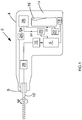
- Figure 1 is a schematic of a power tool embodying the present invention.
- a power tool 2 comprises a housing 4 and an electric motor 6 disposed in the housing 4.
- a rotary output 8 is driven by the motor 6.
- the power tool 2 is a hammer drill having a transmission 10 adapted to both rotate the rotary output 8 to rotate a bit 12 and also impart a reciprocal hammering action to bit 12 as will be familiar to persons skilled in the art.
- a mechanical clutch 28 is configured to disconnect drive from the motor 6 to the rotary output 8 when the torque M encountered by the rotary output 8 exceeds a predetermined threshold.
- the power tool also comprises a handle portion 14 formed in housing 4 and a trigger 16 to enable a user input to drive the motor 6.
- a power source 18 is provided which may be either a battery or a corded connection to the mains as will be familiar to persons skilled in the art.
- Electronic sensing means configured to sense operating parameters of the power tool includes a voltage sensor 20 arranged to detect the voltage across the electric motor 6, a current sensor 22 arranged to detect the current through the tool 2 and a speed sensor 24 arranged to detect the angular velocity ⁇ of the output spindle 8.
- the electronic sensing means is therefore arranged to provide parameter output signals including voltage parameter output signal 20V, current parameter output signal 22i and rotary output speed parameter output signal 24 ⁇ to an electronic control apparatus 26.
- the electronic control apparatus 26 is microprocessor based and is configured to determine from the operating parameter output signals 20V, 22i and 24 ⁇ the torque M of the rotary output 8.
- the electronic control apparatus 26 is also configured to control the angular velocity ⁇ of the rotary output 8 in response to the calculation of the torque of the rotary output 8.
- the electronic control apparatus 28 is operable to change the angular velocity ⁇ of the rotary output when a predetermined value of torque M is exceeded. For example, the motor speed may be reduced to reduce angular velocity. Alternatively, the motor 6 may be switched off or the electronic control apparatus 26 could provide a signal to actuate mechanical clutch 28.
- the torque M of the rotary output 8 is calculated as set out below.
- the symbols used are as follows: Symbol Quantity i current through the whole tool 2 u voltage across the motor 6 ⁇ angular velocity of rotary output 8 n motor armature speed M torque of rotary output 8 P power T period time ⁇ efficiency N Number of samples/line cycle
- the electrical power input into the power tool 2 P el
- P el the electrical power input into the power tool 2
- the mechanical power output P mech is also equal to an efficiency factor ⁇ multiplied by the electrical power to account for the power losses which incur internally within the power tool 2, for example friction in transmission 10, sound, vibration and heat.
- the efficiency ⁇ of the hammer drill is determined in advance using a test rig and is programmed into electronic control apparatus 26 in the form of a look up table.
- the mechanical clutch 28 can be entirely independent of the electronic control apparatus 26 and therefore a two-torque clutching system is provided.
- mechanical clutch 28 in one embodiment is a high torque clutch which is operable at all times.
- the electronic clutch provided by electronic control apparatus 26 is a low torque clutch operable as a safety feature. During operation of the power tool 4, a user can deactivate the low torque electronic clutch provided by electronic control apparatus 26.
Landscapes
- Engineering & Computer Science (AREA)
- Mechanical Engineering (AREA)
- Control Of Electric Motors In General (AREA)
- Percussive Tools And Related Accessories (AREA)
Abstract
Description
- The present invention relates to a power tool, and relates particularly, but not exclusively to a power tool comprising an electronic control apparatus. The present invention also relates to an electronic control system for a power tool.
- Rotary power tools such as drills and hammer drills generally have clutch mechanisms to prevent damage to the tool and danger to the user if the bit becomes stuck when rotating. Both mechanical and electrical clutches are known which disconnect rotary drive from the bit when the torque encountered by the bit passes a predetermined threshold indicating that the bit is impeded or stuck. This is known as a blocking event.
-
EP1539434B1 describes various embodiments of mechanical and electronic clutches used in a rotary hammer drill. For example, one embodiment describes using an accelerometer to provide signals to a microprocessor which analyses acceleration of the tool housing to determine when a blocking event is occurring. The microprocessor can then provide a signal to operate an electromagnet which causes a mechanical clutch to actuate and disconnect drive from the motor to the spindle. -
EP1539434B1 also describes a two-torque mechanical clutch. The two-torque mechanical clutch has two torque settings. A low torque setting is the default setting at which the clutch slips when the torque encountered by the bit exceeds a predetermined low torque threshold. However, a user can manually select a higher torque setting to increase the level of torque encountered by the bit at which the clutch slips. As a safety feature, after operation of the tool the clutch automatically defaults to the low torque setting to prevent the user initiating the tool in the high torque setting. The user must select the high torque setting during operation. - Electronic clutches are also known which measure the current being drawn by a power tool. When the current exceeds a predetermined threshold, the motor is turned off. This type of clutch suffers from the drawback that it does not take into account speed and mode settings of the tool.
- Preferred embodiments of the present invention seek to overcome the above disadvantages of the prior art.
- According to an aspect of the present invention, there is provided a power tool comprising:
- a housing;
- an electric motor disposed in the housing;
- a rotary output driven by said electric motor;
- electronic sensing means configured to sense operating parameters of the power tool including the voltage across the electric motor, the current drawn by the power tool and the angular velocity of the rotary output and provide parameter output signals derived from said sensed operating parameters; and
- an electronic control apparatus configured to determine from said operating parameter output signals the torque of said rotary output and control the angular velocity of the rotary output in response to the calculation of the torque of said rotary output.
- This provides the advantage of a power tool that is able to control the angular velocity of its rotary output by detecting the torque of the rotary output. This enables the power tool to have an electronic clutch that can be actuated at a predetermined level of torque. Since it is torque that is determined rather than current or acceleration of the housing, the detection of spurious blocking events can be minimised which means that the clutch does not slip at undesirable times for the user.
- In a preferred embodiment, said electronic control apparatus determines the torque of said rotary output by calculating a function of a tool efficiency, the voltage across the electric motor, the current through the power tool and the inverse of the angular velocity of the rotary output provided by said operating parameter output signals.
- This provides the advantage of a reliable means for calculating the torque of the rotary output.
- In a preferred embodiment, said tool efficiency is provided to said electronic control apparatus from data in a look up table.
- In a preferred embodiment, said electronic control apparatus is configured to continuously or discretely sample said operating parameter output signals to determine the torque of said rotary output of said power tool.
- Said electronic control apparatus may be configured to reduce the angular velocity of the rotary output in response to the calculation of the torque of said rotary output by reducing the speed of the electric motor.
- Said electronic control apparatus may be configured to switch off the electric motor in response to calculation of a torque exceeding a predetermined value.
- Said electronic control apparatus may be configured to actuate clutch means to deactivate said rotary output in response to calculation of a torque exceeding a predetermined value.
- The power tool may comprise a mechanical clutch configured to disconnect drive from the electric motor to the rotary output in response to the torque of said rotary output exceeding a predetermined threshold.
- This provides the advantage of reducing the number of mechanical parts required for a two-torque clutch system.
- According to another aspect of the present invention, there is provided an electronic control system for a power tool, the system comprising:
- electronic sensing means configured to sense operating parameters of a power tool in use, wherein said power tool comprises an electric motor and a rotary output driven by said electric motor and wherein said operating parameters include the voltage across the electric motor, the current drawn by the power tool and the angular velocity of the rotary output; and
- wherein said electronic sensing means is configured to provide parameter output signals derived from said sensed operating parameters; and
- an electronic control apparatus configured to determine from said operating parameter output signals the torque of said rotary output and control the angular velocity of the rotary output in response to the calculation of the torque of said rotary output.
- This provides the advantage of an electronic control system for a power tool that is able to control the angular velocity of the rotary output by detecting the torque of the rotary output. This enables the power tool to have an electronic clutch that can be actuated at a predetermined level of torque. Since it is torque that is determined rather than current or acceleration of the housing, the detection of spurious blocking events can be minimised which means that the clutch does not slip at undesirable times for the user.
- In a preferred embodiment, said electronic control apparatus is configured to determine the torque of said rotary output by calculating a function of a tool efficiency, the voltage across the electric motor, the current through the power tool and the inverse of the angular velocity of the rotary output provided by said operating parameter output signals.
- This provides the advantage of a reliable means for calculating the torque of the rotary output.
- In a preferred embodiment, said tool efficiency is provided to said electronic control apparatus from data in a look up table.
- In a preferred embodiment, said electronic control apparatus is configured to continuously or discretely sample said operating parameter output signals to determine the torque of said rotary output.
- Said electronic control apparatus may be configured to reduce the angular velocity of the rotary output in response to the calculation of the torque of said rotary output by reducing the speed of the electric motor.
- Said electronic control apparatus may be configured to switch off the electric motor in response to calculation of a torque exceeding a predetermined value.
- Said electronic control apparatus may be configured to actuate clutch means to deactivate said rotary output in response to calculation of a torque exceeding a predetermined value.
- Preferred embodiments of the present invention will now be described, by way of example only and not in any limitative sense, with reference to the accompanying drawings in which:
Figure 1 is a schematic of a power tool embodying the present invention. - Referring to
Figure 1 , apower tool 2 comprises a housing 4 and anelectric motor 6 disposed in the housing 4. Arotary output 8 is driven by themotor 6. In the embodiment shown, thepower tool 2 is a hammer drill having atransmission 10 adapted to both rotate therotary output 8 to rotate abit 12 and also impart a reciprocal hammering action tobit 12 as will be familiar to persons skilled in the art. Amechanical clutch 28 is configured to disconnect drive from themotor 6 to therotary output 8 when the torque M encountered by therotary output 8 exceeds a predetermined threshold. - The power tool also comprises a
handle portion 14 formed in housing 4 and atrigger 16 to enable a user input to drive themotor 6. Apower source 18 is provided which may be either a battery or a corded connection to the mains as will be familiar to persons skilled in the art. - Electronic sensing means configured to sense operating parameters of the power tool includes a
voltage sensor 20 arranged to detect the voltage across theelectric motor 6, acurrent sensor 22 arranged to detect the current through thetool 2 and aspeed sensor 24 arranged to detect the angular velocity ω of theoutput spindle 8. The electronic sensing means is therefore arranged to provide parameter output signals including voltage parameter output signal 20V, currentparameter output signal 22i and rotary output speed parameter output signal 24ω to anelectronic control apparatus 26. - The
electronic control apparatus 26 is microprocessor based and is configured to determine from the operatingparameter output signals 20V, 22i and 24ω the torque M of therotary output 8. Theelectronic control apparatus 26 is also configured to control the angular velocity ω of therotary output 8 in response to the calculation of the torque of therotary output 8. Theelectronic control apparatus 28 is operable to change the angular velocity ω of the rotary output when a predetermined value of torque M is exceeded. For example, the motor speed may be reduced to reduce angular velocity. Alternatively, themotor 6 may be switched off or theelectronic control apparatus 26 could provide a signal to actuatemechanical clutch 28. - The torque M of the
rotary output 8 is calculated as set out below. In the following equations, the symbols used are as follows:Symbol Quantity i current through the whole tool 2 u voltage across the motor 6ω angular velocity of rotary output 8 n motor armature speed M torque of rotary output 8 P power T period time µ efficiency N Number of samples/line cycle - It is known that the electrical power input into the
power tool 2, Pel, is a function of voltage across themotor 6 and the current through thepower tool 2. Theelectronic control apparatus 26 samples either continuously or discretely voltageparameter output signal 20v provided byvoltage sensor 20 and currentparameter output signal 22i provided bycurrent sensor 22. When these parameter outputs are monitored continuously, the average power is provided by:
- Where the current and voltage are sampled discretely at time intervals N, the average power is provided by:

- The angular velocity ω of
rotary output 8 is determined byspeed sensor 24 providing speed output parameter signal 24w to the electronic control apparatus. It is known that the mechanical power output, Pmech, is equal to the product of the output torque and the angular velocity of rotary output 8:
- The mechanical power output Pmech is also equal to an efficiency factor µ multiplied by the electrical power to account for the power losses which incur internally within the
power tool 2, for example friction intransmission 10, sound, vibration and heat. In the case of discrete sampling, this gives:
- The above equation can be rearranged to give an equation for the value of torque M in terms of current and voltage:

- The efficiency µ of the hammer drill is determined in advance using a test rig and is programmed into
electronic control apparatus 26 in the form of a look up table. - The mechanical clutch 28 can be entirely independent of the
electronic control apparatus 26 and therefore a two-torque clutching system is provided. For example, mechanical clutch 28 in one embodiment is a high torque clutch which is operable at all times. The electronic clutch provided byelectronic control apparatus 26 is a low torque clutch operable as a safety feature. During operation of the power tool 4, a user can deactivate the low torque electronic clutch provided byelectronic control apparatus 26. - It will be appreciated by persons skilled in the art that the above embodiments have been described by way of example only and not in any limitative sense, and that various alterations and modifications are possible without departure from the scope of the invention as defined by the appended claims. For example, the electronic control system described can be used with any rotary power tool that requires a clutch, such as saws, routers etc. The electronic control system comprising
electronic control apparatus 26 and electronic sensing means 20, 22, 24 could be provided as an upgrade to existing power tools.
Claims (15)
- A power tool comprising:a housing;an electric motor disposed in the housing;a rotary output driven by said electric motor;electronic sensing means configured to sense operating parameters of the power tool including the voltage across the electric motor, the current drawn by the power tool and the angular velocity of the rotary output and provide parameter output signals derived from said sensed operating parameters; andan electronic control apparatus configured to determine from said operating parameter output signals the torque of said rotary output and control the angular velocity of the rotary output in response to the calculation of the torque of said rotary output.
- A power tool according to claim 1, wherein said electronic control apparatus determines the torque of said rotary output by calculating a function of a tool efficiency, the voltage across the electric motor, the current through the power tool and the inverse of the angular velocity of the rotary output provided by said operating parameter output signals.
- A power tool according to claim 2, wherein said tool efficiency is provided to said electronic control apparatus from data in a look up table.
- A power tool according to claim 2, wherein said electronic control apparatus is configured to continuously or discretely sample said operating parameter output signals to determine the torque of said rotary output of said power tool.
- A power tool according to any one of the preceding claims, wherein said electronic control apparatus is configured to reduce the angular velocity of the rotary output in response to the calculation of the torque of said rotary output by reducing the speed of the electric motor.
- A power tool according to any one of the preceding claims, wherein said electronic control apparatus is configured to switch off the electric motor in response to calculation of a torque exceeding a predetermined value.
- A power tool according to any one of the preceding claims, wherein said electronic control apparatus is configured to actuate clutch means to deactivate said rotary output in response to calculation of a torque exceeding a predetermined value.
- A power tool according to any of the preceding claims, further comprising a mechanical clutch configured to disconnect drive from the electric motor to the rotary output in response to the torque of said rotary output exceeding a predetermined threshold.
- An electronic control system for a power tool, the system comprising:electronic sensing means configured to sense operating parameters of a power tool in use, wherein said power tool comprises an electric motor and a rotary output driven by said electric motor and wherein said operating parameters include the voltage across the electric motor, the current drawn by the power tool and the angular velocity of the rotary output; andwherein said electronic sensing means is configured to provide parameter output signals derived from said sensed operating parameters; andan electronic control apparatus configured to determine from said operating parameter output signals the torque of said rotary output and control the angular velocity of the rotary output in response to the calculation of the torque of said rotary output.
- An electronic control system according to claim 9, wherein said electronic control apparatus is configured to determine the torque of said rotary output by calculating a function of a tool efficiency, the voltage across the electric motor, the current through the power tool and the inverse of the angular velocity of the rotary output provided by said operating parameter output signals.
- An electronic control system according to claim 10, wherein said tool efficiency is provided to said electronic control apparatus from data in a look up table.
- An electronic control system according to claim 10, wherein said electronic control apparatus is configured to continuously or discretely sample said operating parameter output signals to determine the torque of said rotary output.
- An electronic control system according to any one of claims 9 to 12, wherein said electronic control apparatus is configured to reduce the angular velocity of the rotary output in response to the calculation of the torque of said rotary output by reducing the speed of the electric motor.
- An electronic control system according to any one of claims 9 to 13, wherein said electronic control apparatus is configured to switch off the electric motor in response to calculation of a torque exceeding a predetermined value.
- An electronic control system according to any one of claims 9 to 14, wherein said electronic control apparatus is configured to actuate clutch means to deactivate said rotary output in response to calculation of a torque exceeding a predetermined value.
Applications Claiming Priority (1)
| Application Number | Priority Date | Filing Date | Title |
|---|---|---|---|
| GB1813167.2A GB2576314A (en) | 2018-08-13 | 2018-08-13 | Power tool |
Publications (2)
| Publication Number | Publication Date |
|---|---|
| EP3623107A1 true EP3623107A1 (en) | 2020-03-18 |
| EP3623107B1 EP3623107B1 (en) | 2021-07-21 |
Family
ID=63667102
Family Applications (1)
| Application Number | Title | Priority Date | Filing Date |
|---|---|---|---|
| EP19181160.3A Active EP3623107B1 (en) | 2018-08-13 | 2019-06-19 | Electronic control system for a power tool |
Country Status (3)
| Country | Link |
|---|---|
| US (1) | US11219993B2 (en) |
| EP (1) | EP3623107B1 (en) |
| GB (1) | GB2576314A (en) |
Families Citing this family (6)
| Publication number | Priority date | Publication date | Assignee | Title |
|---|---|---|---|---|
| US10850380B2 (en) * | 2015-06-02 | 2020-12-01 | Milwaukee Electric Tool Corporation | Multi-speed power tool with electronic clutch |
| GB2614558A (en) * | 2022-01-07 | 2023-07-12 | Black & Decker Inc | A vacuum cleaner, controller, and a method therefor |
| JP7417899B2 (en) * | 2020-04-23 | 2024-01-19 | パナソニックIpマネジメント株式会社 | Power tool systems, control methods, and programs |
| US11845173B2 (en) | 2020-10-16 | 2023-12-19 | Milwaukee Electric Tool Corporation | Anti bind-up control for power tools |
| US12434371B2 (en) | 2022-03-23 | 2025-10-07 | Milwaukee Electric Tool Corporation | Electronic clutch for power tools |
| US12122028B2 (en) | 2022-05-26 | 2024-10-22 | Milwaukee Electric Tool Corporation | Electronic clutch for powered fastener driver |
Citations (7)
| Publication number | Priority date | Publication date | Assignee | Title |
|---|---|---|---|---|
| EP1398119A1 (en) * | 2002-09-11 | 2004-03-17 | Black & Decker Inc. | Safety cut-off for power tool with rotating tool bit |
| EP1539434A1 (en) | 2002-09-13 | 2005-06-15 | Black & Decker Inc. | Rotary tool |
| DE102007062727A1 (en) * | 2007-12-27 | 2009-07-02 | Robert Bosch Gmbh | Device and method for taking a safety measure in a power tool |
| EP2338646A2 (en) * | 2009-12-16 | 2011-06-29 | HILTI Aktiengesellschaft | Control method for a handheld machine tool and machine tool |
| WO2011100988A1 (en) * | 2010-02-17 | 2011-08-25 | Gardena Manufacturing Gmbh | Power tools |
| DE102012216602A1 (en) * | 2012-09-18 | 2014-03-20 | Robert Bosch Gmbh | Electric power tool i.e. cordless screwdriver, has motor comprising motor shaft, and gear box formed with two gears, where tool is switched between gears when characteristic of tool reaches threshold value that is defined by user of tool |
| EP3050676A1 (en) * | 2015-01-30 | 2016-08-03 | Illinois Tool Works Inc. | Power hand tool with enhanced feedback |
Family Cites Families (15)
| Publication number | Priority date | Publication date | Assignee | Title |
|---|---|---|---|---|
| IT1271878B (en) * | 1994-03-10 | 1997-06-09 | Cml Costr Mecc Liri Srl | ELECTRIC MOTOR FOR PORTABLE MACHINE TOOLS. |
| JP5402030B2 (en) * | 2009-02-02 | 2014-01-29 | マックス株式会社 | Electric tool and motor rotation control method |
| JP5852509B2 (en) * | 2012-05-29 | 2016-02-03 | 株式会社マキタ | Electric tool |
| JP6085488B2 (en) * | 2013-01-28 | 2017-02-22 | 株式会社マキタ | Electric tool |
| JP2014172163A (en) * | 2013-03-13 | 2014-09-22 | Panasonic Corp | Electric tool |
| DE102014209009A1 (en) * | 2014-01-27 | 2015-07-30 | Robert Bosch Gmbh | Machine tool device |
| JP6304533B2 (en) * | 2014-03-04 | 2018-04-04 | パナソニックIpマネジメント株式会社 | Impact rotary tool |
| DE102014219392A1 (en) * | 2014-09-25 | 2016-03-31 | Robert Bosch Gmbh | Sensor device, in particular hand-held power tool sensor device |
| EP3023200A1 (en) * | 2014-11-20 | 2016-05-25 | HILTI Aktiengesellschaft | Control method for a hammer drill |
| EP3023202A1 (en) * | 2014-11-20 | 2016-05-25 | HILTI Aktiengesellschaft | Security method and handheld machine tool |
| EP3028821A1 (en) * | 2014-12-03 | 2016-06-08 | HILTI Aktiengesellschaft | Control method for a hand-held machine tool |
| US10850380B2 (en) * | 2015-06-02 | 2020-12-01 | Milwaukee Electric Tool Corporation | Multi-speed power tool with electronic clutch |
| DE102015226185A1 (en) * | 2015-12-21 | 2017-06-22 | Robert Bosch Gmbh | Hand tool system |
| KR101957437B1 (en) * | 2016-07-21 | 2019-03-12 | 주식회사 아임삭 | Electronic Tool having Hitting Function and Hitting Method of the Same |
| JP6757226B2 (en) * | 2016-10-07 | 2020-09-16 | 株式会社マキタ | Electric tool |
-
2018
- 2018-08-13 GB GB1813167.2A patent/GB2576314A/en not_active Withdrawn
-
2019
- 2019-06-19 EP EP19181160.3A patent/EP3623107B1/en active Active
- 2019-07-26 US US16/523,123 patent/US11219993B2/en active Active
Patent Citations (7)
| Publication number | Priority date | Publication date | Assignee | Title |
|---|---|---|---|---|
| EP1398119A1 (en) * | 2002-09-11 | 2004-03-17 | Black & Decker Inc. | Safety cut-off for power tool with rotating tool bit |
| EP1539434A1 (en) | 2002-09-13 | 2005-06-15 | Black & Decker Inc. | Rotary tool |
| DE102007062727A1 (en) * | 2007-12-27 | 2009-07-02 | Robert Bosch Gmbh | Device and method for taking a safety measure in a power tool |
| EP2338646A2 (en) * | 2009-12-16 | 2011-06-29 | HILTI Aktiengesellschaft | Control method for a handheld machine tool and machine tool |
| WO2011100988A1 (en) * | 2010-02-17 | 2011-08-25 | Gardena Manufacturing Gmbh | Power tools |
| DE102012216602A1 (en) * | 2012-09-18 | 2014-03-20 | Robert Bosch Gmbh | Electric power tool i.e. cordless screwdriver, has motor comprising motor shaft, and gear box formed with two gears, where tool is switched between gears when characteristic of tool reaches threshold value that is defined by user of tool |
| EP3050676A1 (en) * | 2015-01-30 | 2016-08-03 | Illinois Tool Works Inc. | Power hand tool with enhanced feedback |
Also Published As
| Publication number | Publication date |
|---|---|
| US20200047321A1 (en) | 2020-02-13 |
| GB2576314A (en) | 2020-02-19 |
| US11219993B2 (en) | 2022-01-11 |
| GB201813167D0 (en) | 2018-09-26 |
| EP3623107B1 (en) | 2021-07-21 |
Similar Documents
| Publication | Publication Date | Title |
|---|---|---|
| EP3623107B1 (en) | Electronic control system for a power tool | |
| EP1470898B1 (en) | Control system and method for a power tool | |
| JP7085370B2 (en) | Diagnostic equipment, diagnostic systems, diagnostic methods and programs | |
| US10668612B2 (en) | Hand-held power tool | |
| EP1881382A2 (en) | Adaptive control scheme for detecting and preventing torque conditions in a power tool | |
| US6981557B2 (en) | Process for controlling an axially hammering and rotating electric hand-held machine tool | |
| US9579783B2 (en) | Power tool having improved operability | |
| US6479958B1 (en) | Anti-kickback and breakthrough torque control for power tool | |
| EP1982798A3 (en) | Power tool | |
| US12151355B2 (en) | Fault detection methods for power tools | |
| US5857166A (en) | Tool monitoring apparatus | |
| EP2085755A1 (en) | Power Tool having Motor Speed Monitor | |
| JP2016083759A (en) | Processing state monitoring method and system for work machine | |
| US20240159137A1 (en) | A feed unit for feeding a core drill bit into a work object | |
| EP3960371A1 (en) | Machine and method for running a machine | |
| EP1569327A3 (en) | Pulse motor driving device, pulse motor driving method, timepiece device and timepiece device control method | |
| EP0808011A1 (en) | Anti-kickback and breakthrough torque control for power tool | |
| EP0086114A1 (en) | Electrical tool having speed control circuit | |
| US12083664B2 (en) | Method for detecting a slip clutch release event, and power tool | |
| CN104847639A (en) | Measurement and control system and measurement and control method for electric compressor | |
| JP4804914B2 (en) | Gas meter | |
| JPH1133882A (en) | Tool breakage judging method | |
| JPS61182574A (en) | Foreknowing device for tool breakage | |
| CN121625311A (en) | A method, system, cutting tool, and storage medium for protecting cutting tools from recoil. | |
| US20220125264A1 (en) | Vacuum Cleaner, Controller, and a Method Therefor |
Legal Events
| Date | Code | Title | Description |
|---|---|---|---|
| PUAI | Public reference made under article 153(3) epc to a published international application that has entered the european phase |
Free format text: ORIGINAL CODE: 0009012 |
|
| STAA | Information on the status of an ep patent application or granted ep patent |
Free format text: STATUS: THE APPLICATION HAS BEEN PUBLISHED |
|
| AK | Designated contracting states |
Kind code of ref document: A1 Designated state(s): AL AT BE BG CH CY CZ DE DK EE ES FI FR GB GR HR HU IE IS IT LI LT LU LV MC MK MT NL NO PL PT RO RS SE SI SK SM TR |
|
| AX | Request for extension of the european patent |
Extension state: BA ME |
|
| STAA | Information on the status of an ep patent application or granted ep patent |
Free format text: STATUS: REQUEST FOR EXAMINATION WAS MADE |
|
| 17P | Request for examination filed |
Effective date: 20200915 |
|
| RBV | Designated contracting states (corrected) |
Designated state(s): AL AT BE BG CH CY CZ DE DK EE ES FI FR GB GR HR HU IE IS IT LI LT LU LV MC MK MT NL NO PL PT RO RS SE SI SK SM TR |
|
| GRAP | Despatch of communication of intention to grant a patent |
Free format text: ORIGINAL CODE: EPIDOSNIGR1 |
|
| STAA | Information on the status of an ep patent application or granted ep patent |
Free format text: STATUS: GRANT OF PATENT IS INTENDED |
|
| RIC1 | Information provided on ipc code assigned before grant |
Ipc: H02H 7/085 20060101ALI20210211BHEP Ipc: B25B 21/00 20060101AFI20210211BHEP Ipc: B25B 23/147 20060101ALI20210211BHEP Ipc: B25F 5/00 20060101ALI20210211BHEP |
|
| INTG | Intention to grant announced |
Effective date: 20210312 |
|
| GRAS | Grant fee paid |
Free format text: ORIGINAL CODE: EPIDOSNIGR3 |
|
| GRAA | (expected) grant |
Free format text: ORIGINAL CODE: 0009210 |
|
| STAA | Information on the status of an ep patent application or granted ep patent |
Free format text: STATUS: THE PATENT HAS BEEN GRANTED |
|
| AK | Designated contracting states |
Kind code of ref document: B1 Designated state(s): AL AT BE BG CH CY CZ DE DK EE ES FI FR GB GR HR HU IE IS IT LI LT LU LV MC MK MT NL NO PL PT RO RS SE SI SK SM TR |
|
| REG | Reference to a national code |
Ref country code: GB Ref legal event code: FG4D |
|
| REG | Reference to a national code |
Ref country code: CH Ref legal event code: EP |
|
| REG | Reference to a national code |
Ref country code: DE Ref legal event code: R096 Ref document number: 602019006213 Country of ref document: DE |
|
| REG | Reference to a national code |
Ref country code: AT Ref legal event code: REF Ref document number: 1412167 Country of ref document: AT Kind code of ref document: T Effective date: 20210815 |
|
| REG | Reference to a national code |
Ref country code: IE Ref legal event code: FG4D |
|
| REG | Reference to a national code |
Ref country code: LT Ref legal event code: MG9D |
|
| REG | Reference to a national code |
Ref country code: NL Ref legal event code: MP Effective date: 20210721 |
|
| REG | Reference to a national code |
Ref country code: AT Ref legal event code: MK05 Ref document number: 1412167 Country of ref document: AT Kind code of ref document: T Effective date: 20210721 |
|
| PG25 | Lapsed in a contracting state [announced via postgrant information from national office to epo] |
Ref country code: HR Free format text: LAPSE BECAUSE OF FAILURE TO SUBMIT A TRANSLATION OF THE DESCRIPTION OR TO PAY THE FEE WITHIN THE PRESCRIBED TIME-LIMIT Effective date: 20210721 Ref country code: NO Free format text: LAPSE BECAUSE OF FAILURE TO SUBMIT A TRANSLATION OF THE DESCRIPTION OR TO PAY THE FEE WITHIN THE PRESCRIBED TIME-LIMIT Effective date: 20211021 Ref country code: NL Free format text: LAPSE BECAUSE OF FAILURE TO SUBMIT A TRANSLATION OF THE DESCRIPTION OR TO PAY THE FEE WITHIN THE PRESCRIBED TIME-LIMIT Effective date: 20210721 Ref country code: PT Free format text: LAPSE BECAUSE OF FAILURE TO SUBMIT A TRANSLATION OF THE DESCRIPTION OR TO PAY THE FEE WITHIN THE PRESCRIBED TIME-LIMIT Effective date: 20211122 Ref country code: LT Free format text: LAPSE BECAUSE OF FAILURE TO SUBMIT A TRANSLATION OF THE DESCRIPTION OR TO PAY THE FEE WITHIN THE PRESCRIBED TIME-LIMIT Effective date: 20210721 Ref country code: AT Free format text: LAPSE BECAUSE OF FAILURE TO SUBMIT A TRANSLATION OF THE DESCRIPTION OR TO PAY THE FEE WITHIN THE PRESCRIBED TIME-LIMIT Effective date: 20210721 Ref country code: BG Free format text: LAPSE BECAUSE OF FAILURE TO SUBMIT A TRANSLATION OF THE DESCRIPTION OR TO PAY THE FEE WITHIN THE PRESCRIBED TIME-LIMIT Effective date: 20211021 Ref country code: SE Free format text: LAPSE BECAUSE OF FAILURE TO SUBMIT A TRANSLATION OF THE DESCRIPTION OR TO PAY THE FEE WITHIN THE PRESCRIBED TIME-LIMIT Effective date: 20210721 Ref country code: RS Free format text: LAPSE BECAUSE OF FAILURE TO SUBMIT A TRANSLATION OF THE DESCRIPTION OR TO PAY THE FEE WITHIN THE PRESCRIBED TIME-LIMIT Effective date: 20210721 Ref country code: ES Free format text: LAPSE BECAUSE OF FAILURE TO SUBMIT A TRANSLATION OF THE DESCRIPTION OR TO PAY THE FEE WITHIN THE PRESCRIBED TIME-LIMIT Effective date: 20210721 Ref country code: FI Free format text: LAPSE BECAUSE OF FAILURE TO SUBMIT A TRANSLATION OF THE DESCRIPTION OR TO PAY THE FEE WITHIN THE PRESCRIBED TIME-LIMIT Effective date: 20210721 |
|
| PG25 | Lapsed in a contracting state [announced via postgrant information from national office to epo] |
Ref country code: PL Free format text: LAPSE BECAUSE OF FAILURE TO SUBMIT A TRANSLATION OF THE DESCRIPTION OR TO PAY THE FEE WITHIN THE PRESCRIBED TIME-LIMIT Effective date: 20210721 Ref country code: LV Free format text: LAPSE BECAUSE OF FAILURE TO SUBMIT A TRANSLATION OF THE DESCRIPTION OR TO PAY THE FEE WITHIN THE PRESCRIBED TIME-LIMIT Effective date: 20210721 Ref country code: GR Free format text: LAPSE BECAUSE OF FAILURE TO SUBMIT A TRANSLATION OF THE DESCRIPTION OR TO PAY THE FEE WITHIN THE PRESCRIBED TIME-LIMIT Effective date: 20211022 |
|
| REG | Reference to a national code |
Ref country code: DE Ref legal event code: R097 Ref document number: 602019006213 Country of ref document: DE |
|
| PG25 | Lapsed in a contracting state [announced via postgrant information from national office to epo] |
Ref country code: DK Free format text: LAPSE BECAUSE OF FAILURE TO SUBMIT A TRANSLATION OF THE DESCRIPTION OR TO PAY THE FEE WITHIN THE PRESCRIBED TIME-LIMIT Effective date: 20210721 |
|
| PLBE | No opposition filed within time limit |
Free format text: ORIGINAL CODE: 0009261 |
|
| STAA | Information on the status of an ep patent application or granted ep patent |
Free format text: STATUS: NO OPPOSITION FILED WITHIN TIME LIMIT |
|
| PG25 | Lapsed in a contracting state [announced via postgrant information from national office to epo] |
Ref country code: SM Free format text: LAPSE BECAUSE OF FAILURE TO SUBMIT A TRANSLATION OF THE DESCRIPTION OR TO PAY THE FEE WITHIN THE PRESCRIBED TIME-LIMIT Effective date: 20210721 Ref country code: SK Free format text: LAPSE BECAUSE OF FAILURE TO SUBMIT A TRANSLATION OF THE DESCRIPTION OR TO PAY THE FEE WITHIN THE PRESCRIBED TIME-LIMIT Effective date: 20210721 Ref country code: RO Free format text: LAPSE BECAUSE OF FAILURE TO SUBMIT A TRANSLATION OF THE DESCRIPTION OR TO PAY THE FEE WITHIN THE PRESCRIBED TIME-LIMIT Effective date: 20210721 Ref country code: EE Free format text: LAPSE BECAUSE OF FAILURE TO SUBMIT A TRANSLATION OF THE DESCRIPTION OR TO PAY THE FEE WITHIN THE PRESCRIBED TIME-LIMIT Effective date: 20210721 Ref country code: CZ Free format text: LAPSE BECAUSE OF FAILURE TO SUBMIT A TRANSLATION OF THE DESCRIPTION OR TO PAY THE FEE WITHIN THE PRESCRIBED TIME-LIMIT Effective date: 20210721 Ref country code: AL Free format text: LAPSE BECAUSE OF FAILURE TO SUBMIT A TRANSLATION OF THE DESCRIPTION OR TO PAY THE FEE WITHIN THE PRESCRIBED TIME-LIMIT Effective date: 20210721 |
|
| 26N | No opposition filed |
Effective date: 20220422 |
|
| PG25 | Lapsed in a contracting state [announced via postgrant information from national office to epo] |
Ref country code: IT Free format text: LAPSE BECAUSE OF FAILURE TO SUBMIT A TRANSLATION OF THE DESCRIPTION OR TO PAY THE FEE WITHIN THE PRESCRIBED TIME-LIMIT Effective date: 20210721 |
|
| PG25 | Lapsed in a contracting state [announced via postgrant information from national office to epo] |
Ref country code: MC Free format text: LAPSE BECAUSE OF FAILURE TO SUBMIT A TRANSLATION OF THE DESCRIPTION OR TO PAY THE FEE WITHIN THE PRESCRIBED TIME-LIMIT Effective date: 20210721 |
|
| REG | Reference to a national code |
Ref country code: CH Ref legal event code: PL |
|
| REG | Reference to a national code |
Ref country code: BE Ref legal event code: MM Effective date: 20220630 |
|
| PG25 | Lapsed in a contracting state [announced via postgrant information from national office to epo] |
Ref country code: LU Free format text: LAPSE BECAUSE OF NON-PAYMENT OF DUE FEES Effective date: 20220619 Ref country code: LI Free format text: LAPSE BECAUSE OF NON-PAYMENT OF DUE FEES Effective date: 20220630 Ref country code: IE Free format text: LAPSE BECAUSE OF NON-PAYMENT OF DUE FEES Effective date: 20220619 Ref country code: FR Free format text: LAPSE BECAUSE OF NON-PAYMENT OF DUE FEES Effective date: 20220630 Ref country code: CH Free format text: LAPSE BECAUSE OF NON-PAYMENT OF DUE FEES Effective date: 20220630 |
|
| PG25 | Lapsed in a contracting state [announced via postgrant information from national office to epo] |
Ref country code: BE Free format text: LAPSE BECAUSE OF NON-PAYMENT OF DUE FEES Effective date: 20220630 |
|
| PG25 | Lapsed in a contracting state [announced via postgrant information from national office to epo] |
Ref country code: MK Free format text: LAPSE BECAUSE OF FAILURE TO SUBMIT A TRANSLATION OF THE DESCRIPTION OR TO PAY THE FEE WITHIN THE PRESCRIBED TIME-LIMIT Effective date: 20210721 Ref country code: CY Free format text: LAPSE BECAUSE OF FAILURE TO SUBMIT A TRANSLATION OF THE DESCRIPTION OR TO PAY THE FEE WITHIN THE PRESCRIBED TIME-LIMIT Effective date: 20210721 |
|
| PG25 | Lapsed in a contracting state [announced via postgrant information from national office to epo] |
Ref country code: HU Free format text: LAPSE BECAUSE OF FAILURE TO SUBMIT A TRANSLATION OF THE DESCRIPTION OR TO PAY THE FEE WITHIN THE PRESCRIBED TIME-LIMIT; INVALID AB INITIO Effective date: 20190619 |
|
| PG25 | Lapsed in a contracting state [announced via postgrant information from national office to epo] |
Ref country code: MT Free format text: LAPSE BECAUSE OF FAILURE TO SUBMIT A TRANSLATION OF THE DESCRIPTION OR TO PAY THE FEE WITHIN THE PRESCRIBED TIME-LIMIT Effective date: 20210721 |
|
| PGFP | Annual fee paid to national office [announced via postgrant information from national office to epo] |
Ref country code: DE Payment date: 20250618 Year of fee payment: 7 |
|
| PGFP | Annual fee paid to national office [announced via postgrant information from national office to epo] |
Ref country code: GB Payment date: 20250620 Year of fee payment: 7 |
|
| PG25 | Lapsed in a contracting state [announced via postgrant information from national office to epo] |
Ref country code: TR Free format text: LAPSE BECAUSE OF FAILURE TO SUBMIT A TRANSLATION OF THE DESCRIPTION OR TO PAY THE FEE WITHIN THE PRESCRIBED TIME-LIMIT Effective date: 20210721 |