EP3622885B1 - Voice control system for ophthalmic laser systems - Google Patents
Voice control system for ophthalmic laser systems Download PDFInfo
- Publication number
- EP3622885B1 EP3622885B1 EP19196932.8A EP19196932A EP3622885B1 EP 3622885 B1 EP3622885 B1 EP 3622885B1 EP 19196932 A EP19196932 A EP 19196932A EP 3622885 B1 EP3622885 B1 EP 3622885B1
- Authority
- EP
- European Patent Office
- Prior art keywords
- parameter
- parameters
- voice command
- regulation module
- command information
- Prior art date
- Legal status (The legal status is an assumption and is not a legal conclusion. Google has not performed a legal analysis and makes no representation as to the accuracy of the status listed.)
- Active
Links
Images





Classifications
-
- G—PHYSICS
- G10—MUSICAL INSTRUMENTS; ACOUSTICS
- G10L—SPEECH ANALYSIS TECHNIQUES OR SPEECH SYNTHESIS; SPEECH RECOGNITION; SPEECH OR VOICE PROCESSING TECHNIQUES; SPEECH OR AUDIO CODING OR DECODING
- G10L15/00—Speech recognition
- G10L15/22—Procedures used during a speech recognition process, e.g. man-machine dialogue
-
- A—HUMAN NECESSITIES
- A61—MEDICAL OR VETERINARY SCIENCE; HYGIENE
- A61B—DIAGNOSIS; SURGERY; IDENTIFICATION
- A61B17/00—Surgical instruments, devices or methods
-
- A—HUMAN NECESSITIES
- A61—MEDICAL OR VETERINARY SCIENCE; HYGIENE
- A61F—FILTERS IMPLANTABLE INTO BLOOD VESSELS; PROSTHESES; DEVICES PROVIDING PATENCY TO, OR PREVENTING COLLAPSING OF, TUBULAR STRUCTURES OF THE BODY, e.g. STENTS; ORTHOPAEDIC, NURSING OR CONTRACEPTIVE DEVICES; FOMENTATION; TREATMENT OR PROTECTION OF EYES OR EARS; BANDAGES, DRESSINGS OR ABSORBENT PADS; FIRST-AID KITS
- A61F9/00—Methods or devices for treatment of the eyes; Devices for putting in contact-lenses; Devices to correct squinting; Apparatus to guide the blind; Protective devices for the eyes, carried on the body or in the hand
- A61F9/007—Methods or devices for eye surgery
- A61F9/008—Methods or devices for eye surgery using laser
-
- A—HUMAN NECESSITIES
- A61—MEDICAL OR VETERINARY SCIENCE; HYGIENE
- A61F—FILTERS IMPLANTABLE INTO BLOOD VESSELS; PROSTHESES; DEVICES PROVIDING PATENCY TO, OR PREVENTING COLLAPSING OF, TUBULAR STRUCTURES OF THE BODY, e.g. STENTS; ORTHOPAEDIC, NURSING OR CONTRACEPTIVE DEVICES; FOMENTATION; TREATMENT OR PROTECTION OF EYES OR EARS; BANDAGES, DRESSINGS OR ABSORBENT PADS; FIRST-AID KITS
- A61F9/00—Methods or devices for treatment of the eyes; Devices for putting in contact-lenses; Devices to correct squinting; Apparatus to guide the blind; Protective devices for the eyes, carried on the body or in the hand
- A61F9/007—Methods or devices for eye surgery
- A61F9/008—Methods or devices for eye surgery using laser
- A61F9/00821—Methods or devices for eye surgery using laser for coagulation
-
- A—HUMAN NECESSITIES
- A61—MEDICAL OR VETERINARY SCIENCE; HYGIENE
- A61B—DIAGNOSIS; SURGERY; IDENTIFICATION
- A61B17/00—Surgical instruments, devices or methods
- A61B2017/00017—Electrical control of surgical instruments
- A61B2017/00203—Electrical control of surgical instruments with speech control or speech recognition
-
- A—HUMAN NECESSITIES
- A61—MEDICAL OR VETERINARY SCIENCE; HYGIENE
- A61B—DIAGNOSIS; SURGERY; IDENTIFICATION
- A61B5/00—Measuring for diagnostic purposes; Identification of persons
- A61B5/74—Details of notification to user or communication with user or patient; User input means
- A61B5/7475—User input or interface means, e.g. keyboard, pointing device, joystick
- A61B5/749—Voice-controlled interfaces
-
- A—HUMAN NECESSITIES
- A61—MEDICAL OR VETERINARY SCIENCE; HYGIENE
- A61F—FILTERS IMPLANTABLE INTO BLOOD VESSELS; PROSTHESES; DEVICES PROVIDING PATENCY TO, OR PREVENTING COLLAPSING OF, TUBULAR STRUCTURES OF THE BODY, e.g. STENTS; ORTHOPAEDIC, NURSING OR CONTRACEPTIVE DEVICES; FOMENTATION; TREATMENT OR PROTECTION OF EYES OR EARS; BANDAGES, DRESSINGS OR ABSORBENT PADS; FIRST-AID KITS
- A61F9/00—Methods or devices for treatment of the eyes; Devices for putting in contact-lenses; Devices to correct squinting; Apparatus to guide the blind; Protective devices for the eyes, carried on the body or in the hand
- A61F9/007—Methods or devices for eye surgery
- A61F9/008—Methods or devices for eye surgery using laser
- A61F2009/00861—Methods or devices for eye surgery using laser adapted for treatment at a particular location
- A61F2009/00863—Retina
-
- A—HUMAN NECESSITIES
- A61—MEDICAL OR VETERINARY SCIENCE; HYGIENE
- A61F—FILTERS IMPLANTABLE INTO BLOOD VESSELS; PROSTHESES; DEVICES PROVIDING PATENCY TO, OR PREVENTING COLLAPSING OF, TUBULAR STRUCTURES OF THE BODY, e.g. STENTS; ORTHOPAEDIC, NURSING OR CONTRACEPTIVE DEVICES; FOMENTATION; TREATMENT OR PROTECTION OF EYES OR EARS; BANDAGES, DRESSINGS OR ABSORBENT PADS; FIRST-AID KITS
- A61F9/00—Methods or devices for treatment of the eyes; Devices for putting in contact-lenses; Devices to correct squinting; Apparatus to guide the blind; Protective devices for the eyes, carried on the body or in the hand
- A61F9/007—Methods or devices for eye surgery
- A61F9/008—Methods or devices for eye surgery using laser
- A61F2009/00861—Methods or devices for eye surgery using laser adapted for treatment at a particular location
- A61F2009/00868—Ciliary muscles or trabecular meshwork
-
- A—HUMAN NECESSITIES
- A61—MEDICAL OR VETERINARY SCIENCE; HYGIENE
- A61F—FILTERS IMPLANTABLE INTO BLOOD VESSELS; PROSTHESES; DEVICES PROVIDING PATENCY TO, OR PREVENTING COLLAPSING OF, TUBULAR STRUCTURES OF THE BODY, e.g. STENTS; ORTHOPAEDIC, NURSING OR CONTRACEPTIVE DEVICES; FOMENTATION; TREATMENT OR PROTECTION OF EYES OR EARS; BANDAGES, DRESSINGS OR ABSORBENT PADS; FIRST-AID KITS
- A61F9/00—Methods or devices for treatment of the eyes; Devices for putting in contact-lenses; Devices to correct squinting; Apparatus to guide the blind; Protective devices for the eyes, carried on the body or in the hand
- A61F9/007—Methods or devices for eye surgery
- A61F9/008—Methods or devices for eye surgery using laser
- A61F2009/00885—Methods or devices for eye surgery using laser for treating a particular disease
- A61F2009/00891—Glaucoma
-
- G—PHYSICS
- G10—MUSICAL INSTRUMENTS; ACOUSTICS
- G10L—SPEECH ANALYSIS TECHNIQUES OR SPEECH SYNTHESIS; SPEECH RECOGNITION; SPEECH OR VOICE PROCESSING TECHNIQUES; SPEECH OR AUDIO CODING OR DECODING
- G10L15/00—Speech recognition
- G10L15/06—Creation of reference templates; Training of speech recognition systems, e.g. adaptation to the characteristics of the speaker's voice
- G10L15/065—Adaptation
- G10L15/07—Adaptation to the speaker
-
- G—PHYSICS
- G10—MUSICAL INSTRUMENTS; ACOUSTICS
- G10L—SPEECH ANALYSIS TECHNIQUES OR SPEECH SYNTHESIS; SPEECH RECOGNITION; SPEECH OR VOICE PROCESSING TECHNIQUES; SPEECH OR AUDIO CODING OR DECODING
- G10L15/00—Speech recognition
- G10L15/08—Speech classification or search
-
- G—PHYSICS
- G10—MUSICAL INSTRUMENTS; ACOUSTICS
- G10L—SPEECH ANALYSIS TECHNIQUES OR SPEECH SYNTHESIS; SPEECH RECOGNITION; SPEECH OR VOICE PROCESSING TECHNIQUES; SPEECH OR AUDIO CODING OR DECODING
- G10L15/00—Speech recognition
- G10L15/22—Procedures used during a speech recognition process, e.g. man-machine dialogue
- G10L2015/223—Execution procedure of a spoken command
-
- G—PHYSICS
- G10—MUSICAL INSTRUMENTS; ACOUSTICS
- G10L—SPEECH ANALYSIS TECHNIQUES OR SPEECH SYNTHESIS; SPEECH RECOGNITION; SPEECH OR VOICE PROCESSING TECHNIQUES; SPEECH OR AUDIO CODING OR DECODING
- G10L15/00—Speech recognition
- G10L15/22—Procedures used during a speech recognition process, e.g. man-machine dialogue
- G10L2015/225—Feedback of the input speech
Definitions
- slit lamps are used for delivering the laser energy to the patient's eye.
- the patients sit up in an examination chair, rest their chin on a chin rest, and place their forehead against a forehead band, both of which keep the patient's head in place during the procedure.
- WO 2018/146070 discloses an apparatus for photothermal ophthalmic treatment, in particular photocoagulation or photo-thermal stimulation.
- This prior art apparatus includes a uer interface which allows the user to select the desired parameters, either by voice command or direct selection via e.g. knobs or a touchscreen interface.
- LIO Laser Indirect Ophthalmoscope
- Current systems use a laser console for generating the laser light and a long fiber optic umbilical coupled to the LIO.
- the laser console includes a laser source, a power source (for example, providing AC/DC conversion), laser drive and parameter control systems, and a user interface.
- the user interface comprises physical knobs and switches or a touchscreen and can be part of the laser console itself or a remote control device that communicates with the laser console.
- Activation devices e.g. footswitches
- the doctor moves the laser console, which is positioned on a cart or table, to be in the proximity of the patient who is usually in a supine position.
- the doctor then walks around the patient to deliver the laser energy to the desired portions of the retina. If a parameter change is needed, the doctor physically returns to the laser console to make the change or has an assistant, for example, standing next to the laser console, make the change.
- the present invention includes a voice control system for ophthalmologic laser treatment systems that is robust against operator mistakes and misunderstood commands, for example, by replaying and confirming voice commands, evaluating desired parameters against a predetermined safety policy, and providing incremental parameter adjustment and restricting the amount by which the parameters can be increased and/or decreased for each executed voice command.
- the voice control system includes a voice control module for recognizing spoken commands and a parameter regulation module for generating parameter information based on the spoken commands and a predetermined safety policy. Audible feedback of current and updated parameters is also provided.
- a microphone first detects a wake word (which is a special phrase to indicate that verbal commands follow).
- the wake word provides a two-step recognition requirement for voice commands in order to make a parameter change, decreasing the likelihood of an erroneous parameter change.
- a tone is played after the wake word is detected to prompt the user to provide the voice command.
- the microphone captures audio data, and the voice control module recognizes in the audio data a spoken command (in any multitude of languages) from a predetermined set of commands.
- the parameter regulation module then generates the parameter information based on which commands and other spoken information were recognized by the voice control module.
- the parameter regulation module only increases the power and duration set points by 20% or less of the current set points, and the valid voice commands are limited to indicating which parameter to adjust and whether to adjust the parameter up or down.
- voice commands can include "Power up,” “Power down,” “Duration up,” “Duration down,” “Interval up,” “Interval down,” “Aiming beam up,” and “Aiming beam down,” to list a few examples.
- the amount by which the parameters can be increased or decreased can be restricted based on multiple considerations, including, for example, a prescribed tolerance band for set parameters according to industry regulations.
- voice control functionality can be selectively executed under certain conditions to further enhance the safety of the laser treatment system.
- voice commands to change the interval parameter are not executed when it is determined that the user had not previously specified a repeat interval for the current laser treatment session.
- the invention features a system for delivering laser energy to an eye of a patient comprising a microphone, a voice control module, an parameter regulation module, and a control module.
- the microphone captures audio data.
- the voice control module receives the captured audio data and generates voice command information based on the captured audio data.
- the parameter regulation module generates parameter information based on the voice command information.
- the control module receives the parameter information and sets the parameters for the delivered laser energy based on the parameter information.
- the voice control module generates the voice command information by recognizing spoken language in the captured audio data, which can indicate the parameters to be adjusted, values for the parameters and/or whether values for the parameters should be increased or decreased.
- the microphone captures the audio data in response to detecting a predetermined wake word, and audible feedback confirming the parameter information and/or the voice command information is provided via speakers.
- Both the voice control module and the parameter regulation module can execute on a mobile computing device of a body-mounted laser-indirect ophthalmoscope system, a laser console of a laser-indirect ophthalmoscope system, and/or a user terminal of an ophthalmic laser treatment system.
- the parameter regulation module generates the parameter information based on current values for the parameters to be set and/or a predetermined safety policy, which can indicate maximum values and/or percentages by which the parameters can be increased and/or decreased, predetermined sequences of possible values for the parameters, whether setting of parameters in response to voice commands is selectively executed based on the current parameters, and/or other criteria indicating that the parameters are potentially unsafe.
- a predetermined safety policy can indicate maximum values and/or percentages by which the parameters can be increased and/or decreased, predetermined sequences of possible values for the parameters, whether setting of parameters in response to voice commands is selectively executed based on the current parameters, and/or other criteria indicating that the parameters are potentially unsafe.
- Audio data is captured, and voice command information based on the captured audio data is generated. Parameter information is then generated based on the voice command information. The parameters for the delivered laser energy are set based on the parameter information.
- the term “and/or” includes any and all combinations of one or more of the associated listed items. Further, the singular forms and the articles “a”, “an” and “the” are intended to include the plural forms as well, unless expressly stated otherwise. It will be further understood that the terms: includes, comprises, including and/or comprising, when used in this specification, specify the presence of stated features, integers, steps, operations, elements, and/or components, but do not preclude the presence or addition of one or more other features, integers, steps, operations, elements, components, and/or groups thereof. Further, it will be understood that when an element, including component or subsystem, is referred to and/or shown as being connected or coupled to another element, it can be directly connected or coupled to the other element or intervening elements may be present.
- the present invention concerns a voice control system for different ophthalmic laser treatment devices.
- Figs. 1-6 concern exemplary ophthalmic laser treatment systems that have been augmented according to the present invention.
- Fig. 1 is an illustration of a body-mounted LIO system 100-1.
- the body-mounted LIO system 100 delivers laser energy to an eye of a patient.
- a user of the LIO system 100-1 is typically a doctor such as an ophthalmologist.
- the body-mounted LIO system 100-1 includes a binocular indirect ophthalmoscope 120, a control module 108, a power module 110, a laser module 112 and a mobile computing device 104.
- the binocular indirect ophthalmoscope 120 is an optical device for examining the inside of the eye of the patient.
- the binocular indirect ophthalmoscope 120 includes an illumination unit 114 for providing white light and an optical system including a viewing aperture 118 and an exit aperture 116 from which the laser energy is emitted (which is also an entrance aperture for image information e.g. for viewing the patient's eye).
- the power module 110 provides power to the control module 108 and the laser module 112. In one embodiment, the power module 110 also provides power to the illumination unit 114 of the binocular indirect ophthalmoscope 120.
- the laser module 112 produces and emits the pulsed laser energy according to certain user-provided parameters such as pulse envelope duration, peak power, and micropulse duration and interval, among other examples.
- the activation device 106 which is part of the user interface of the body-mounted LIO system 100-1, is a device that receives user input via an activation mechanism (e.g. a switch or button) and in response sends activation signals to the control module 108 indicating that the laser energy should be emitted.
- the activation device 106 is typically a footswitch, and engagement with the activation mechanism includes compression of the footswitch by the user's foot, for example.
- the mobile computing device 120 is a tablet computer.
- the mobile computing device 120 could be a smartphone device, laptop computer, or phablet computer (i.e., a mobile device that is typically larger than a smart phone, but smaller than a tablet), to list a few examples.
- the mobile computing device 104 provides additional components of the user interface and generates parameter information indicating the user-provided parameters based on input received via the user interface and sends the parameter information to the control module 108.
- the user interface further includes a voice control interface that allows the user to indicate parameter information using verbal commands.
- the user provides a verbal command (e.g. "Power 200", "Power up"), and the mobile computing device provides audible feedback confirming the command, for example, by calling out the parameter being adjusted.
- a verbal command e.g. "Power 200", "Power up”
- the mobile computing device provides audible feedback confirming the command, for example, by calling out the parameter being adjusted.
- the audible feedback calls out the name of the parameter and the next highest increment from the starting point (e.g. "Power at 225").
- the control module 108 controls the laser energy delivered by the laser module 112 based on parameter information received from the mobile computing device 104 and activation signals received from the activation device 106.
- the control module 108 communicates with the activation device 106 and the mobile computing device 104 wirelessly.
- the control module 108 sets the parameters for the laser energy.
- the control module 108 sends control signals reflecting the user-provided parameters to the laser module 112 activating the laser module and causing it to produce and/or emit the laser energy.
- the body-mounted LIO system 100-1 includes a wearable assembly 102, which secures the body-mounted LIO system 100-1 to the user's body via one or more wearable objects such as a headset, a utility belt, or a backpack, among other examples.
- the wearable assembly 102 comprises only a headset 102-1, which is worn on the user's head.
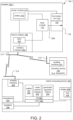
- Fig. 2 is a block diagram of the body-mounted LIO system 100-1 according to the preferred embodiment showing the components of the system in more detail. Specifically, internal components of the headset 102-1, the activation device 106, and the mobile computing device 104 are shown.
- the mobile computing device 104 includes a central processing unit (CPU) 222, a touchscreen display 230, a wireless interface 222 and antenna 218, a microphone 234 and speakers 236.
- CPU central processing unit
- the CPU 222 executes firmware/operating system instructions and sends instructions and data to and receives data from the wireless interface 220, the microphone 234, the speakers 236, and the display 230.
- Executing on typically an operating system (OS) 224 of the CPU 222 are a mobile application 226, a voice control module 228, and an parameter regulation module 229.
- the mobile application 226 renders a graphical user interface (GUI) 232 on the touchscreen display 230.
- the GUI 232 which is part of the user interface of the body-mounted LIO system 100-1, displays and receives information such as parameter information, for example, by detecting contact between the user and the touchscreen display 230 in certain regions of the touchscreen display 230.
- the mobile application 226 also performs functions related to configuring the LIO system 100 such as pairing the mobile computing device 104 with the control module 108 and/or setting a wake word, which is a selected phrase for indicating that verbal commands follow.
- the microphone 234 captures sound including the wake word and voice commands indicating parameter information provided by the user, which the mobile computing device 104 converts to audio data.
- the speakers 236 produce sound based on instructions from the parameter regulation module 229, for example, in order to provide audible feedback confirming parameter information and/or voice commands.
- the voice control module 228 generates voice command information based on the captured audio data.
- the voice control module 228 recognizes spoken language in the audio data and translates the spoken language to commands that can be interpreted by the parameter regulation module 229 and/or executed by the control module 108.
- the parameter regulation module 229 generates parameter information based on the voice command information generated by the voice control module 228, current parameters for delivering the laser energy, and/or a predetermined safety policy. In generating the parameter information, the parameter regulation module 229 also controls and limits the ability of voice commands generated by the voice control module to enact changes to the parameters for the delivered laser energy.
- the parameter regulation module 229 maintains a set of voice commands that are recognized and translated to parameter information. These valid voice commands might include indicating which parameter to set or adjust and what value to set for the parameter or whether to adjust the parameter up or down in order to provide incremental voice command functionality. These voice commands can include "Power 200,” “Power up,” “Power down,” “Duration up,” “Duration down,” “Interval up,” “Interval down,” “Aiming beam up,” “Aiming beam down,” “Pulse duration up,” “Pulse duration down,” to list a few examples.
- the parameter regulation module 229 further provides the audible feedback confirming the voice command information and/or parameter information by sending instructions to the speakers 236 to produce sound, for example, repeating back the voice commands interpreted by the parameter regulation module 229 and/or parameter information. Additionally, the parameter regulation module 229 evaluates the generated parameter information against a predetermined safety policy (for example, based on predetermined criteria in the safety policy for determining when parameters are potentially unsafe) and seeks extra confirmation of the voice command information and/or the parameter information if the parameter information is determined to be unsafe based on the safety policy.
- a predetermined safety policy for example, based on predetermined criteria in the safety policy for determining when parameters are potentially unsafe
- the parameter regulation module 229 provides audible feedback repeating the voice command and then waits for input from the user interface (e.g. further voice command information generated by the voice control module 228 based on sound detected by the microphone 234) before proceeding to generate the parameter information.
- the parameter regulation module 229 determines that the parameters indicated by the parameter information generated based on the voice command information are unsafe and alerts the user (e.g. via sound produced by the speakers 236) that the parameters are unsafe and/or requires extra confirmation from the user (e.g. via sound captured by the microphone 234) before proceeding to send the parameter information to the control module 108.
- the parameter regulation module 229 generates the parameter information, for example, by increasing or decreasing current parameter values by predetermined values or percentages.
- the parameter regulation module 229 calculates an adjusted parameter value that is no more than a predetermined percentage of the current value.
- the predetermined percentage for setting the power parameter might be 20%, meaning that the power parameter can only be increased and/or decreased by 20% of the current value in response to voice commands.
- the voice commands "aiming beam up” or “aiming beam down” results in no greater than a 10% change in intensity.
- the parameter regulation module 229 iterates through sequences of predetermined values for particular parameters, selecting from the predetermined sequence a value that is higher or lower than the current parameter value in response to the voice command information.
- a finite set of all possible power settings indicated by the predetermined safety policy might include 50, 60, 70, 80, 90, 100, 110, 120, 130, 140, 150, 175, 200, 225, 250, 275, 300, 325, 350, 375, 400, 425, 450, 475, 500 milliwatts (mW), continuing in 50mW increments to 1500 mW.
- the parameter regulation module 229 would generate parameter information indicating that the parameters should be set to 110 mW in response to the voice command "power up” and 90 mW in response to the voice command "power down.” In this way, the parameter regulation module 229 prevents the parameters from being inadvertently adjusted from 100 mW to 1500 mW, for example, in response to a misspoken or misunderstood voice command.
- a finite set of all possible duration settings indicated by the predetermined adjustment criteria might include 10, 11, 12, 13, 14, 15, 17, 20, 22, 25, 30, 35, 40, 45, 50, 60, 70, 80, 90, 100, 112, 125, 150, 175, 200, 225, 250, 300, 350, 400, 450, 500, 600, 700, 800, 900, 1000 milliseconds (ms).
- the parameter regulation module 229 also determines whether particular parameters can or can not be set in response to voice commands based on the current parameter information. For example, the parameter regulation module 229 might determine that the interval setting was set to "OFF", or that no interval parameter value was initially provided, and automatically ignore voice commands for the interval parameter in order to prevent the interval parameter from being accidentally set. In this way, the module 229 applies a safety policy that prevents the operator from changing the parameters in a way that could be detrimental to patient health.
- the voice control module 228, microphone 234, speakers 236, GUI 232 rendered on the touchscreen display 230, and the activation device 106 provide a general user interface (UI) for the LIO system 100.
- the UI for the LIO system 100 can also include other user interface elements 237 such as physical input mechanisms such as knobs or buttons, which can be part of the mobile computing device 104 itself or part of peripheral devices connected to the mobile computing device 104 via the wireless interface 220 and/or a physical interface (e.g. data port).
- the parameter information can be generated by the mobile computing device 104 based on any user engagement with the mobile computing device 104 and/or peripheral devices.
- the wireless network interface 220 facilitates sending the parameter information to the control module 108 via the antenna 218 through a wireless communication link with the control module 108 according to wireless personal area network (WPAN) or wireless local area network (WLAN) protocols such as Bluetooth Low Energy (BLE) or WiFi, among other examples.
- WPAN wireless personal area network
- WLAN wireless local area network
- BLE Bluetooth Low Energy
- WiFi Wireless Fidelity
- the power module 110 includes a battery 210, which supplies the power provided to the control module 108, laser module 112 and illumination unit 114. Among other functions, the power module 110 performs the functions of a battery management system (e.g. preventing the battery from operating outside its Safe Operating Area, monitoring its state, etc.).
- a battery management system e.g. preventing the battery from operating outside its Safe Operating Area, monitoring its state, etc.
- the laser module 112 includes a fiber optic cable 206 for emitting the laser energy.
- the fiber optic cable 206 is routed through the binocular indirect ophthalmoscope 120 such that the laser energy is emitted from the exit aperture 116.
- the control module 108 includes a CPU 202 and a wireless interface 204.
- the CPU 202 directs the functionality of the control module 108 such as receiving parameter information from the mobile computing device 104 and activation signals from the activation device 106 via the wireless interface 204 and an antenna 212, as well as sending control signals to the laser module 112.
- the activation device 106 includes a wireless interface 214 and an antenna 216 through which activation signals are sent to the control module 108.
- the activation device 106 is a wired foot switch with a wired interface through which activations are sent to the control module 108.
- the voice control module also performs the functions of user interface associated with the activation device. For example, in response to a voice command such as "execute", the device could activate the laser.
- Fig. 3 is an illustration of a table-top LIO system 100-2 to which the present invention is applicable.
- the table-top LIO system 100-2 includes a laser console 103 and a headset 102-2.
- the headset 102-2 includes the binocular indirect ophthalmoscope 120 and the illumination unit 114 as before.
- the laser console receives the user input via a user interface of the laser console 103, which can include a graphical user interface 232, or other input and display elements such as knobs, dials, keypads and/or buttons generates the parameter information, and drives the laser via a longer fiber optic cable 206 which is routed to the laser console 103.
- the laser console 103 receives input from the activation device 106 via a wired connection.
- Fig. 4 is a schematic diagram of the table-top LIO system 100-2.
- the laser console 103 includes the control module 108, the power module 110 and the laser module 112.
- the activation device 106 includes a wired interface 240, and likewise the control module 108 includes a wired interface 238. Instead of sending the activation signals wirelessly to the control module 108, the activation device 106 sends the signals via a wired connection between the two devices.
- the laser console 103 now includes the microphone 234 and the speakers 236.
- the laser console 103 receives the user input via the graphical user interface 232 and/or an additional physical user interface 237, which can include input and display elements such as knobs, dials, keypads and/or buttons.
- the control module 108 sets the parameters for the delivered laser energy based on parameter information.
- the voice control module 228 and the parameter regulation module 229 execute on the CPU 202 of the control module 108.
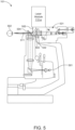
- Fig. 5 schematically shows a slit lamp device 101 to which the present invention is applicable.
- the figure schematically shows the previously described laser module 112-a that produces the pulsed laser energy and that is attached to the slit lamp 101 via a tonometer mount.
- the slit lamp includes a magnifying optical device 531, such as a microscope or zoom telescope, configured to receive light at a viewing input 532 along a viewing path 503 from a target area.
- the central part of the slit lamp 101 includes a white light source 501 that is used to illuminate a target area in the eye 502 of the patient.
- This white light is directed, by means of a mirror 504, onto an illumination output path 511 that coincides with the optical viewing path 503 of the operator at the designed focal point of the diagnostic instrument at the target area.
- the light 505 from the laser is directed towards the target area along a treatment beam path such that it coincides with the viewing path, at least at the target area.
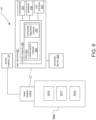
- Fig. 6 is a schematic diagram of the slit lamp device 101.
- the slit lamp device 101 comprises a diagnostic instrument 906 and an adapter unit 112-a mounted to the diagnostic instrument 906.
- the system further comprises a user terminal 951 in wireless communication with the adapter unit 112-a, and the power module 110 electrically coupled to the adapter unit 112-a.
- the power module 110 provides DC operating power to the adapter unit 112-a and the user terminal 951 provides the user interface 237 to the operator and communicates control commands to the adapter unit 112-a.
- the power module 110 may be battery-powered or configured to receive external power, e.g. AC power.
- the power module 110 may also be integrated into or directly attached to the housing of the adapter unit 112-a; for example, the adapter unit 112-a may comprise a replaceable, e.g. rechargeable, battery.
- the user terminal 951 may further receive values of operational parameters such as performance parameters from the adapter unit.
- the power module 110 and the user terminal 951 may be embodied as separate units or as a single control unit.
- the user terminal 951 provides a voice interface allowing for a hands-free control of performance parameters of the adapter unit 112-a.
- the user terminal 951 includes the microphone 234, and speakers 236 and the voice control module 228 and parameter regulation module 229 execution on the CPU 202.
- the voice recognition system is a self-contained system that operates without the need to communicate with a remote host.
- the voice recognition system may be a distributed system where at least a part of the voice recognition process is performed by a remote host system.
- the user terminal may comprise one or more other user interface devices 237, such as knobs, switches, a display, a touch screen and/or the like.
- the user terminal may further comprise, or be coupled to, the activation device 106.
- the diagnostic instrument comprises a power supply 959, a control unit 957 and an operating console 958, e.g. embodied as separate units or as a single, integrated unit.
- the user terminal 951 for controlling the adapter unit 112-a may be integrated into or separate from the operating console of the diagnostic instrument.
- the power supply unit 952 and the power supply unit 959 may be embodied as separate units or as a single, integrated power supply.
- Fig. 7 is a sequence diagram illustrating the process by which the parameters for delivered laser energy are set based on the captured audio data.
- control module 108 sets initial parameters for the laser energy delivered by the laser module 112 based on the last used parameters, input detected via the GUI 232 or user interface 237, or predetermined default parameters.
- step 802 the activation device 106 detects engagement of the activation mechanism.
- the user's foot compresses a footswitch.
- step 804 the activation device 106 sends an activation signal to the control module 108.
- control module 108 in step 806 sends a control signal to the laser module 112.
- step 808 in response to receiving the control signal, the laser module 112 generates and emits the laser energy according to the parameters set by the control module 108.
- the voice control module 228 detects activation of a voice control mode based on configuration information and/or the predetermined safety policy which might specify situations in which voice control should be selectively executed.
- the voice control module 228 receives captured audio data.
- the mobile computing device 104, the laser console 103 or the user terminal 951 which continuously and in real time monitors audio data captured via the microphone 234 for a predetermined wake word programmed, detects the wake word and, in response, plays a tone through the speakers 236 prompting the user to say the voice command.
- the voice control module 228 then generates audio data based on sound that was captured after the wake word was detected and tone was played and sends the audio data to the voice control module 228.
- the voice control module 228 In step 812, the voice control module 228 generates voice command information based on the captured audio data.
- the audio data includes spoken language such as the phrase "power up”.
- the voice control module 228 sends the voice command information to the parameter regulation module 229 in step 812.
- the parameter regulation module 229 generates parameter information based on the voice command information, the current parameters, and/or the predetermined safety policy. In one example, the parameter regulation module 229 increases or decreases the current parameter value by a predetermined threshold and generates parameter information reflecting the higher or lower value. In another example, the parameter regulation module 229 selects the next highest or lowest value with respect to the current value from a predetermined sequence of possible parameter values. In another example, the parameter regulation module 229 determines whether setting of the particular parameters indicated in the voice command information should be allowed based on, for example, whether voice control of particular parameters is selectively executed.
- step 818 the parameter regulation module 229 sends the parameter information and instructions to set the required parameters to the control module 108.
- Steps 802 through 808 then repeat as previously described, with the laser module 112 delivering laser energy based on the parameters.
- Fig. 8 is a flow diagram illustrating the process by which the parameter regulation module 229 generates parameter information based on the voice command information and the predetermined safety policy, which corresponds to the previously described step 816, for example.
- step 900 the parameter regulation module 229 receives the voice command information from the voice control module 228.
- the parameter regulation module 229 provides audible feedback repeating the voice command information (e.g. via the speakers 236) and prompts the user to confirm that the voice command information generated by the voice control module 228 and received from the parameter regulation module 229 accurately reflects the voice commands spoken by the user.
- step 904 it is determined whether a positive confirmation was received from the user (e.g. based on the voice control module 228 detecting a predetermined confirmation word via the microphone 234). If confirmation was not received after a predetermined time period, the process ends in step 930, and the parameter regulation module 229 does not proceed to change the parameters. In an alternative embodiment, the parameter regulation module 229 does not perform the confirmation of step 904 and simply proceeds after providing the audible feedback.
- the parameter regulation module 229 identifies the particular parameter (e.g. power, duration, interval, aiming beam, pulse duration, pulse interval) to be set or adjusted based on the voice command information.
- the parameter to be set/adjusted is based on, for example, which of a predetermined set of words associated with the parameters was detected and recognized by the voice control module 228.
- the parameter regulation module 229 identifies whether the parameter value is being set directly (e.g. based on recognized phrases corresponding to numerical values such as "200") or incrementally (e.g. based on recognized phrases corresponding to whether the value should be increased or decreased such as "up” or “down”).
- step 910 it is determined whether the parameter is being set incrementally. If not, in step 918, the parameter regulation module 229 generates the parameter information based on the parameter being set and the value indicated by the voice command information.
- step 912 it is determined whether the interval is the parameter being set, and if so, in step 914, it is determined whether the current setting for the interval parameter is "OFF" (or some other indication that an initial value for the interval has not been provided). If the interval parameter is set to "OFF", no change is made, the voice command is ignored, and the process ends in step 930.
- the parameter regulation module 229 retrieves or calculates a value for the parameter based on the predetermined safety policy.
- the policy sets a maximum increase or decrease value or percentage by which the current value is adjusted to calculate the new value.
- the policy provides a predetermined sequence of allowed values according to which the current value is incremented or decremented to the next value in the sequence. The parameter regulation module 229 then generates the parameter information.
- the parameter regulation module 229 evaluates the parameter information based on the predetermined safety policy (for example, based on predetermined criteria in the safety policy for determining when parameters are potentially unsafe). This might include confirming that a parameter value set directly is within a certain difference threshold of the current value or that the value is within a predetermined range, among other examples.
- step 922 it is determined whether the parameters, including the parameter currently being set combined with the other parameters, create a potentially unsafe situation for the patient. If so, in step 924, the parameter regulation module 229 provides audible feedback repeating the generated parameter information (e.g. via the speakers 236) and prompts the user to confirm the parameter being set, possibly with a message informing the user that the parameters are potentially unsafe. In step 926, if no confirmation is received within a predetermined time period, no parameter changes are made, and the process ends in step 930.
- the parameter regulation module 229 sends the parameter information to the control module 108, which corresponds to previously described step 818.
- step 930 the process repeats continually, as the voice control module 228 continually generates voice command information based on audio data from the microphone 229 and sends the voice control information to the parameter regulation module 229.
- the following table includes a set of exemplary voice commands interpreted by the voice command module 228, along with the appropriate action taken in response to the voice commands by the parameter regulation module 229.
- the value N represents the current parameters
- "N+1" and “N-1” are understood to denote the value N incremented or decremented, respectively, according to the safety policy.
- the word “[TONE]” in the "Full Command Set” column indicates where in the sequence of spoken voice commands an audible tone would be played through the speakers 236 (e.g. a sound resembling a beep, chime) to prompt the user to proceed to say the rest of the voice command.
- the word “[MODE]” in the Audible Response column indicates where in the phrase a word corresponding to the current mode of the laser treatment system 100, such as "Treat” mode or "Standby” mode, among other examples.
- the Command column includes different voice commands (e.g. phrases spoken by the user) which are recognized by the voice control module 228.
- the Full Command Set column includes full sequences of wake words, audible tone prompts, and voice commands.
- the Audible Response column includes audible feedback (e.g. phrases) played through the speakers 236 in response to the voice control module 228 recognizing and interpreting the voice commands.
- the System Action column includes actions performed, for example, by the parameter regulation module 229 in response to the voice control module 228 recognizing the voice commands in the Commands column.
- the user in order to execute the "Enter Treat" voice command, the user speaks the wake word “OK Norlase.” An audible tone is then played through the speakers 236, after which the user speaks the voice command "Enter Treat.”
- the parameter regulation module 229 plays the audible feedback phrase "Treat Mode Selected” and then proceeds to place the system into the "Treat” mode, during which parameters can be adjusted and laser energy can be delivered.
- the user in order to execute the "Power Up" voice command, the user speaks the wake word “OK Norlase.” An audible tone is then played through the speakers 236, after which the user speaks the voice command "Power Up.”
- the parameter regulation module 229 plays the audible feedback phrase "Power at [N+1]", referring to the new value of the power parameter and increases the power one increment from the current setting, according to the safety policy and other processes described, for example, with respect to Fig. 8 . For example, if the power is currently set at 120, the audible response would be "Power at 130" to indicate that the power parameter has been increased to 130.
- the parameter regulation module 229 plays the informational audible feedback phrase "[Mode] Mode selected, Power at [N], Duration at [N], Interval at [N], Pulse Count at [N],” referring respectively to the current mode setting and the current values of the power, duration, interval and pulse count.
Landscapes
- Health & Medical Sciences (AREA)
- Engineering & Computer Science (AREA)
- Ophthalmology & Optometry (AREA)
- Surgery (AREA)
- Life Sciences & Earth Sciences (AREA)
- Veterinary Medicine (AREA)
- Physics & Mathematics (AREA)
- Nuclear Medicine, Radiotherapy & Molecular Imaging (AREA)
- Heart & Thoracic Surgery (AREA)
- Animal Behavior & Ethology (AREA)
- General Health & Medical Sciences (AREA)
- Public Health (AREA)
- Biomedical Technology (AREA)
- Optics & Photonics (AREA)
- Vascular Medicine (AREA)
- Molecular Biology (AREA)
- Medical Informatics (AREA)
- Computational Linguistics (AREA)
- Audiology, Speech & Language Pathology (AREA)
- Human Computer Interaction (AREA)
- Acoustics & Sound (AREA)
- Multimedia (AREA)
- Laser Surgery Devices (AREA)
- Radiation-Therapy Devices (AREA)
Description
- There are a number of treatment regimes that involve delivering laser energy to a patient's eye. In these treatments, doctors regularly set and update parameters dictating the laser energy to be delivered. These parameters can include peak power, pulse duration, and repeat interval, among other examples.
- Commonly, slit lamps are used for delivering the laser energy to the patient's eye. In these systems, the patients sit up in an examination chair, rest their chin on a chin rest, and place their forehead against a forehead band, both of which keep the patient's head in place during the procedure.
WO 2018/146070 discloses an apparatus for photothermal ophthalmic treatment, in particular photocoagulation or photo-thermal stimulation. This prior art apparatus includes a uer interface which allows the user to select the desired parameters, either by voice command or direct selection via e.g. knobs or a touchscreen interface. - Another common device is a Laser Indirect Ophthalmoscope (LIO), which is a head mounted device, worn by the doctor to deliver laser energy into a patient's eye. Current systems use a laser console for generating the laser light and a long fiber optic umbilical coupled to the LIO. The laser console includes a laser source, a power source (for example, providing AC/DC conversion), laser drive and parameter control systems, and a user interface. The user interface comprises physical knobs and switches or a touchscreen and can be part of the laser console itself or a remote control device that communicates with the laser console. Activation devices (e.g. footswitches) connect to the laser consoles and activate the laser emission, for example, by sending an activation signal to the laser console in response to engagement of an activation mechanism (e.g. compression of the footswitch).
- During procedures using the LIO, the doctor moves the laser console, which is positioned on a cart or table, to be in the proximity of the patient who is usually in a supine position. The doctor then walks around the patient to deliver the laser energy to the desired portions of the retina. If a parameter change is needed, the doctor physically returns to the laser console to make the change or has an assistant, for example, standing next to the laser console, make the change.
- The present invention includes a voice control system for ophthalmologic laser treatment systems that is robust against operator mistakes and misunderstood commands, for example, by replaying and confirming voice commands, evaluating desired parameters against a predetermined safety policy, and providing incremental parameter adjustment and restricting the amount by which the parameters can be increased and/or decreased for each executed voice command. The voice control system includes a voice control module for recognizing spoken commands and a parameter regulation module for generating parameter information based on the spoken commands and a predetermined safety policy. Audible feedback of current and updated parameters is also provided.
- In one example, a microphone first detects a wake word (which is a special phrase to indicate that verbal commands follow).The wake word provides a two-step recognition requirement for voice commands in order to make a parameter change, decreasing the likelihood of an erroneous parameter change. In one embodiment, a tone is played after the wake word is detected to prompt the user to provide the voice command.
- In response to detecting the wake word, and after the tone is played, the microphone captures audio data, and the voice control module recognizes in the audio data a spoken command (in any multitude of languages) from a predetermined set of commands. The parameter regulation module then generates the parameter information based on which commands and other spoken information were recognized by the voice control module.
- In one example, the parameter regulation module only increases the power and duration set points by 20% or less of the current set points, and the valid voice commands are limited to indicating which parameter to adjust and whether to adjust the parameter up or down. These voice commands can include "Power up," "Power down," "Duration up," "Duration down," "Interval up," "Interval down," "Aiming beam up," and "Aiming beam down," to list a few examples. The amount by which the parameters can be increased or decreased can be restricted based on multiple considerations, including, for example, a prescribed tolerance band for set parameters according to industry regulations.
- Additionally, the voice control functionality can be selectively executed under certain conditions to further enhance the safety of the laser treatment system. In one example, voice commands to change the interval parameter are not executed when it is determined that the user had not previously specified a repeat interval for the current laser treatment session.
- In general, according to one aspect, the invention features a system for delivering laser energy to an eye of a patient comprising a microphone, a voice control module, an parameter regulation module, and a control module. The microphone captures audio data. The voice control module receives the captured audio data and generates voice command information based on the captured audio data. The parameter regulation module generates parameter information based on the voice command information. The control module receives the parameter information and sets the parameters for the delivered laser energy based on the parameter information.
- In embodiments, the voice control module generates the voice command information by recognizing spoken language in the captured audio data, which can indicate the parameters to be adjusted, values for the parameters and/or whether values for the parameters should be increased or decreased. The microphone captures the audio data in response to detecting a predetermined wake word, and audible feedback confirming the parameter information and/or the voice command information is provided via speakers. Both the voice control module and the parameter regulation module can execute on a mobile computing device of a body-mounted laser-indirect ophthalmoscope system, a laser console of a laser-indirect ophthalmoscope system, and/or a user terminal of an ophthalmic laser treatment system. The parameter regulation module generates the parameter information based on current values for the parameters to be set and/or a predetermined safety policy, which can indicate maximum values and/or percentages by which the parameters can be increased and/or decreased, predetermined sequences of possible values for the parameters, whether setting of parameters in response to voice commands is selectively executed based on the current parameters, and/or other criteria indicating that the parameters are potentially unsafe.
- Also described is a method for delivering laser energy to an eye of a patient using an ophthalmic laser treatment system. Audio data is captured, and voice command information based on the captured audio data is generated. Parameter information is then generated based on the voice command information. The parameters for the delivered laser energy are set based on the parameter information.
- The above and other features of the invention including various novel details of construction and combinations of parts, and other advantages, will now be more particularly described with reference to the accompanying drawings and pointed out in the claims. It will be understood that the particular device embodying the invention are shown by way of illustration and not as a limitation of the invention. The principles and features of this invention may be employed in various and numerous embodiments without departing from the scope of the invention. The scope of the invention is defined by the claims which follow. Surgical and/or therapeutic methods described are not part of the claimed subject-matter and given for illustrative purpose only.
- In the accompanying drawings, reference characters refer to the same parts throughout the different views. The drawings are not necessarily to scale; emphasis has instead been placed upon illustrating the principles of the invention. Of the drawings:
-
Fig. 1 is a schematic illustration of an exemplary body-mounted laser-indirect ophthalmoscope (LIO) system to which the present invention is applicable; -
Fig. 2 is a block diagram of the body-mounted LIO system according to the present invention; -
Fig. 3 is a schematic illustration of an exemplary table-top LIO system to which the present invention is also applicable; -
Fig. 4 is a block diagram of the table-top LIO system according to the present invention; -
Fig. 5 is a schematic side cross-sectional view of an exemplary slit lamp system to which the present invention is also applicable; -
Fig. 6 is a block diagram of the slit lamp system according to the present invention; -
Fig. 7 is a sequence diagram illustrating the process by which parameters for delivered laser energy are set based on captured audio data according to the present invention; and -
Fig. 8 is a flow diagram illustrating the process by which the parameter regulation module generates parameter information based on voice command information and a predetermined safety policy. - The invention now will be described more fully hereinafter with reference to the accompanying drawings, in which illustrative embodiments of the invention are shown. This invention may, however, be embodied in many different forms and should not be construed as limited to the embodiments set forth herein; rather, these embodiments are provided so that this disclosure will be thorough and complete, and will fully convey the scope of the invention to those skilled in the art.
- As used herein, the term "and/or" includes any and all combinations of one or more of the associated listed items. Further, the singular forms and the articles "a", "an" and "the" are intended to include the plural forms as well, unless expressly stated otherwise. It will be further understood that the terms: includes, comprises, including and/or comprising, when used in this specification, specify the presence of stated features, integers, steps, operations, elements, and/or components, but do not preclude the presence or addition of one or more other features, integers, steps, operations, elements, components, and/or groups thereof. Further, it will be understood that when an element, including component or subsystem, is referred to and/or shown as being connected or coupled to another element, it can be directly connected or coupled to the other element or intervening elements may be present.
- The present invention concerns a voice control system for different ophthalmic laser treatment devices. In general,
Figs. 1-6 concern exemplary ophthalmic laser treatment systems that have been augmented according to the present invention. -
Fig. 1 is an illustration of a body-mounted LIO system 100-1. In general, the body-mounted LIO system 100 delivers laser energy to an eye of a patient. A user of the LIO system 100-1 is typically a doctor such as an ophthalmologist. - The body-mounted LIO system 100-1 includes a binocular
indirect ophthalmoscope 120, acontrol module 108, apower module 110, alaser module 112 and amobile computing device 104. - The binocular
indirect ophthalmoscope 120 is an optical device for examining the inside of the eye of the patient. The binocularindirect ophthalmoscope 120 includes anillumination unit 114 for providing white light and an optical system including aviewing aperture 118 and anexit aperture 116 from which the laser energy is emitted (which is also an entrance aperture for image information e.g. for viewing the patient's eye). - In general, the
power module 110 provides power to thecontrol module 108 and thelaser module 112. In one embodiment, thepower module 110 also provides power to theillumination unit 114 of the binocularindirect ophthalmoscope 120. - The
laser module 112 produces and emits the pulsed laser energy according to certain user-provided parameters such as pulse envelope duration, peak power, and micropulse duration and interval, among other examples. - The
activation device 106, which is part of the user interface of the body-mounted LIO system 100-1, is a device that receives user input via an activation mechanism (e.g. a switch or button) and in response sends activation signals to thecontrol module 108 indicating that the laser energy should be emitted. Theactivation device 106 is typically a footswitch, and engagement with the activation mechanism includes compression of the footswitch by the user's foot, for example. - Preferably, the
mobile computing device 120 is a tablet computer. Alternatively, themobile computing device 120 could be a smartphone device, laptop computer, or phablet computer (i.e., a mobile device that is typically larger than a smart phone, but smaller than a tablet), to list a few examples. In general, themobile computing device 104 provides additional components of the user interface and generates parameter information indicating the user-provided parameters based on input received via the user interface and sends the parameter information to thecontrol module 108. - In the illustrated example, the user interface further includes a voice control interface that allows the user to indicate parameter information using verbal commands. In one example, the user provides a verbal command (e.g. "Power 200", "Power up"), and the mobile computing device provides audible feedback confirming the command, for example, by calling out the parameter being adjusted. In one example, if the "power" is currently set at 200, and a voice command of "Power up" is given, the audible feedback calls out the name of the parameter and the next highest increment from the starting point (e.g. "Power at 225").
- The
control module 108 controls the laser energy delivered by thelaser module 112 based on parameter information received from themobile computing device 104 and activation signals received from theactivation device 106. In the illustrated example, thecontrol module 108 communicates with theactivation device 106 and themobile computing device 104 wirelessly. In response to receiving the parameter information from themobile computing device 104, thecontrol module 108 sets the parameters for the laser energy. In response to receiving activation signals from theactivation device 106, thecontrol module 108 sends control signals reflecting the user-provided parameters to thelaser module 112 activating the laser module and causing it to produce and/or emit the laser energy. - The body-mounted LIO system 100-1 includes a wearable assembly 102, which secures the body-mounted LIO system 100-1 to the user's body via one or more wearable objects such as a headset, a utility belt, or a backpack, among other examples. In the illustrated example, the wearable assembly 102 comprises only a headset 102-1, which is worn on the user's head.
-
Fig. 2 is a block diagram of the body-mounted LIO system 100-1 according to the preferred embodiment showing the components of the system in more detail. Specifically, internal components of the headset 102-1, theactivation device 106, and themobile computing device 104 are shown. - The
mobile computing device 104 includes a central processing unit (CPU) 222, atouchscreen display 230, awireless interface 222 andantenna 218, amicrophone 234 andspeakers 236. - The
CPU 222 executes firmware/operating system instructions and sends instructions and data to and receives data from thewireless interface 220, themicrophone 234, thespeakers 236, and thedisplay 230. Executing on typically an operating system (OS) 224 of theCPU 222 are amobile application 226, avoice control module 228, and anparameter regulation module 229. Themobile application 226 renders a graphical user interface (GUI) 232 on thetouchscreen display 230. TheGUI 232, which is part of the user interface of the body-mounted LIO system 100-1, displays and receives information such as parameter information, for example, by detecting contact between the user and thetouchscreen display 230 in certain regions of thetouchscreen display 230. Themobile application 226 also performs functions related to configuring the LIO system 100 such as pairing themobile computing device 104 with thecontrol module 108 and/or setting a wake word, which is a selected phrase for indicating that verbal commands follow. - The
microphone 234 captures sound including the wake word and voice commands indicating parameter information provided by the user, which themobile computing device 104 converts to audio data. - The
speakers 236 produce sound based on instructions from theparameter regulation module 229, for example, in order to provide audible feedback confirming parameter information and/or voice commands. - The
voice control module 228 generates voice command information based on the captured audio data. In one example, thevoice control module 228 recognizes spoken language in the audio data and translates the spoken language to commands that can be interpreted by theparameter regulation module 229 and/or executed by thecontrol module 108. - The
parameter regulation module 229 generates parameter information based on the voice command information generated by thevoice control module 228, current parameters for delivering the laser energy, and/or a predetermined safety policy. In generating the parameter information, theparameter regulation module 229 also controls and limits the ability of voice commands generated by the voice control module to enact changes to the parameters for the delivered laser energy. - The
parameter regulation module 229 maintains a set of voice commands that are recognized and translated to parameter information. These valid voice commands might include indicating which parameter to set or adjust and what value to set for the parameter or whether to adjust the parameter up or down in order to provide incremental voice command functionality. These voice commands can include "Power 200," "Power up," "Power down," "Duration up," "Duration down," "Interval up," "Interval down," "Aiming beam up," "Aiming beam down," "Pulse duration up," "Pulse duration down," to list a few examples. - The
parameter regulation module 229 further provides the audible feedback confirming the voice command information and/or parameter information by sending instructions to thespeakers 236 to produce sound, for example, repeating back the voice commands interpreted by theparameter regulation module 229 and/or parameter information. Additionally, theparameter regulation module 229 evaluates the generated parameter information against a predetermined safety policy (for example, based on predetermined criteria in the safety policy for determining when parameters are potentially unsafe) and seeks extra confirmation of the voice command information and/or the parameter information if the parameter information is determined to be unsafe based on the safety policy. - In one example, the
parameter regulation module 229 provides audible feedback repeating the voice command and then waits for input from the user interface (e.g. further voice command information generated by thevoice control module 228 based on sound detected by the microphone 234) before proceeding to generate the parameter information. - In another example, the
parameter regulation module 229 determines that the parameters indicated by the parameter information generated based on the voice command information are unsafe and alerts the user (e.g. via sound produced by the speakers 236) that the parameters are unsafe and/or requires extra confirmation from the user (e.g. via sound captured by the microphone 234) before proceeding to send the parameter information to thecontrol module 108. - Additionally, in some embodiments, the
parameter regulation module 229 generates the parameter information, for example, by increasing or decreasing current parameter values by predetermined values or percentages. In one example, theparameter regulation module 229 calculates an adjusted parameter value that is no more than a predetermined percentage of the current value. The predetermined percentage for setting the power parameter might be 20%, meaning that the power parameter can only be increased and/or decreased by 20% of the current value in response to voice commands. Similarly, the voice commands "aiming beam up" or "aiming beam down" results in no greater than a 10% change in intensity. - In some embodiments, the
parameter regulation module 229 iterates through sequences of predetermined values for particular parameters, selecting from the predetermined sequence a value that is higher or lower than the current parameter value in response to the voice command information. For example, a finite set of all possible power settings indicated by the predetermined safety policy might include 50, 60, 70, 80, 90, 100, 110, 120, 130, 140, 150, 175, 200, 225, 250, 275, 300, 325, 350, 375, 400, 425, 450, 475, 500 milliwatts (mW), continuing in 50mW increments to 1500 mW. If the current power setting is at 100 mW, theparameter regulation module 229 would generate parameter information indicating that the parameters should be set to 110 mW in response to the voice command "power up" and 90 mW in response to the voice command "power down." In this way, theparameter regulation module 229 prevents the parameters from being inadvertently adjusted from 100 mW to 1500 mW, for example, in response to a misspoken or misunderstood voice command. In a similar example, a finite set of all possible duration settings indicated by the predetermined adjustment criteria might include 10, 11, 12, 13, 14, 15, 17, 20, 22, 25, 30, 35, 40, 45, 50, 60, 70, 80, 90, 100, 112, 125, 150, 175, 200, 225, 250, 300, 350, 400, 450, 500, 600, 700, 800, 900, 1000 milliseconds (ms). - The
parameter regulation module 229 also determines whether particular parameters can or can not be set in response to voice commands based on the current parameter information. For example, theparameter regulation module 229 might determine that the interval setting was set to "OFF", or that no interval parameter value was initially provided, and automatically ignore voice commands for the interval parameter in order to prevent the interval parameter from being accidentally set. In this way, themodule 229 applies a safety policy that prevents the operator from changing the parameters in a way that could be detrimental to patient health. - In the illustrated example, the
voice control module 228,microphone 234,speakers 236,GUI 232 rendered on thetouchscreen display 230, and theactivation device 106 provide a general user interface (UI) for the LIO system 100. However, in other embodiments (not illustrated) the UI for the LIO system 100 can also include otheruser interface elements 237 such as physical input mechanisms such as knobs or buttons, which can be part of themobile computing device 104 itself or part of peripheral devices connected to themobile computing device 104 via thewireless interface 220 and/or a physical interface (e.g. data port). In general, the parameter information can be generated by themobile computing device 104 based on any user engagement with themobile computing device 104 and/or peripheral devices. - The
wireless network interface 220 facilitates sending the parameter information to thecontrol module 108 via theantenna 218 through a wireless communication link with thecontrol module 108 according to wireless personal area network (WPAN) or wireless local area network (WLAN) protocols such as Bluetooth Low Energy (BLE) or WiFi, among other examples. - The headset 102-1, as previously discussed, includes the
control module 108, thepower module 110, thelaser module 112, the binocularindirect ophthalmoscope 120 and theillumination unit 114. - The
power module 110 includes abattery 210, which supplies the power provided to thecontrol module 108,laser module 112 andillumination unit 114. Among other functions, thepower module 110 performs the functions of a battery management system (e.g. preventing the battery from operating outside its Safe Operating Area, monitoring its state, etc.). - The
laser module 112 includes afiber optic cable 206 for emitting the laser energy. Thefiber optic cable 206 is routed through the binocularindirect ophthalmoscope 120 such that the laser energy is emitted from theexit aperture 116. - The
control module 108 includes aCPU 202 and a wireless interface 204. TheCPU 202 directs the functionality of thecontrol module 108 such as receiving parameter information from themobile computing device 104 and activation signals from theactivation device 106 via the wireless interface 204 and anantenna 212, as well as sending control signals to thelaser module 112. - Finally, the
activation device 106 includes awireless interface 214 and anantenna 216 through which activation signals are sent to thecontrol module 108. In another embodiment of the body-mounted LIO system 100-1 (not illustrated), theactivation device 106 is a wired foot switch with a wired interface through which activations are sent to thecontrol module 108. - In some embodiments, the voice control module also performs the functions of user interface associated with the activation device. For example, in response to a voice command such as "execute", the device could activate the laser.
-
Fig. 3 is an illustration of a table-top LIO system 100-2 to which the present invention is applicable. - The table-top LIO system 100-2 includes a
laser console 103 and a headset 102-2. The headset 102-2 includes the binocularindirect ophthalmoscope 120 and theillumination unit 114 as before. Now, however, the laser console receives the user input via a user interface of thelaser console 103, which can include agraphical user interface 232, or other input and display elements such as knobs, dials, keypads and/or buttons generates the parameter information, and drives the laser via a longerfiber optic cable 206 which is routed to thelaser console 103. Thelaser console 103 receives input from theactivation device 106 via a wired connection. -
Fig. 4 is a schematic diagram of the table-top LIO system 100-2. Here, thelaser console 103 includes thecontrol module 108, thepower module 110 and thelaser module 112. Additionally, theactivation device 106 includes awired interface 240, and likewise thecontrol module 108 includes awired interface 238. Instead of sending the activation signals wirelessly to thecontrol module 108, theactivation device 106 sends the signals via a wired connection between the two devices. - Additionally, the
laser console 103 now includes themicrophone 234 and thespeakers 236. Thelaser console 103 receives the user input via thegraphical user interface 232 and/or an additionalphysical user interface 237, which can include input and display elements such as knobs, dials, keypads and/or buttons. - The
control module 108, as before, sets the parameters for the delivered laser energy based on parameter information. Now, additionally, thevoice control module 228 and theparameter regulation module 229 execute on theCPU 202 of thecontrol module 108. -
Fig. 5 schematically shows aslit lamp device 101 to which the present invention is applicable. The figure schematically shows the previously described laser module 112-a that produces the pulsed laser energy and that is attached to theslit lamp 101 via a tonometer mount. The slit lamp includes a magnifyingoptical device 531, such as a microscope or zoom telescope, configured to receive light at aviewing input 532 along aviewing path 503 from a target area. The central part of theslit lamp 101 includes awhite light source 501 that is used to illuminate a target area in theeye 502 of the patient. This white light is directed, by means of amirror 504, onto anillumination output path 511 that coincides with theoptical viewing path 503 of the operator at the designed focal point of the diagnostic instrument at the target area. In the same fashion, the light 505 from the laser is directed towards the target area along a treatment beam path such that it coincides with the viewing path, at least at the target area. -
Fig. 6 is a schematic diagram of theslit lamp device 101. Theslit lamp device 101 comprises adiagnostic instrument 906 and an adapter unit 112-a mounted to thediagnostic instrument 906. - The system further comprises a user terminal 951 in wireless communication with the adapter unit 112-a, and the
power module 110 electrically coupled to the adapter unit 112-a. - In the illustrated embodiment, the
power module 110 provides DC operating power to the adapter unit 112-a and the user terminal 951 provides theuser interface 237 to the operator and communicates control commands to the adapter unit 112-a. Thepower module 110 may be battery-powered or configured to receive external power, e.g. AC power. Thepower module 110 may also be integrated into or directly attached to the housing of the adapter unit 112-a; for example, the adapter unit 112-a may comprise a replaceable, e.g. rechargeable, battery. The user terminal 951 may further receive values of operational parameters such as performance parameters from the adapter unit. Thepower module 110 and the user terminal 951 may be embodied as separate units or as a single control unit. The user terminal 951 provides a voice interface allowing for a hands-free control of performance parameters of the adapter unit 112-a. To this end, the user terminal 951 includes themicrophone 234, andspeakers 236 and thevoice control module 228 andparameter regulation module 229 execution on theCPU 202. Preferably, the voice recognition system is a self-contained system that operates without the need to communicate with a remote host. However, in alternative embodiments, the voice recognition system may be a distributed system where at least a part of the voice recognition process is performed by a remote host system. Alternatively or additionally, the user terminal may comprise one or more otheruser interface devices 237, such as knobs, switches, a display, a touch screen and/or the like. The user terminal may further comprise, or be coupled to, theactivation device 106. - The diagnostic instrument comprises a
power supply 959, acontrol unit 957 and anoperating console 958, e.g. embodied as separate units or as a single, integrated unit. The user terminal 951 for controlling the adapter unit 112-a may be integrated into or separate from the operating console of the diagnostic instrument. Similarly, the power supply unit 952 and thepower supply unit 959 may be embodied as separate units or as a single, integrated power supply. -
Fig. 7 is a sequence diagram illustrating the process by which the parameters for delivered laser energy are set based on the captured audio data. - First, in step 800, the
control module 108 sets initial parameters for the laser energy delivered by thelaser module 112 based on the last used parameters, input detected via theGUI 232 oruser interface 237, or predetermined default parameters. - In
step 802, theactivation device 106 detects engagement of the activation mechanism. In one example, the user's foot compresses a footswitch. In response, instep 804, theactivation device 106 sends an activation signal to thecontrol module 108. - In response to receiving the activation signal, the
control module 108 in step 806 sends a control signal to thelaser module 112. - In
step 808, in response to receiving the control signal, thelaser module 112 generates and emits the laser energy according to the parameters set by thecontrol module 108. - In step 809, the
voice control module 228 detects activation of a voice control mode based on configuration information and/or the predetermined safety policy which might specify situations in which voice control should be selectively executed. - In
step 810, thevoice control module 228 receives captured audio data. In one example, themobile computing device 104, thelaser console 103 or the user terminal 951, which continuously and in real time monitors audio data captured via themicrophone 234 for a predetermined wake word programmed, detects the wake word and, in response, plays a tone through thespeakers 236 prompting the user to say the voice command. Thevoice control module 228 then generates audio data based on sound that was captured after the wake word was detected and tone was played and sends the audio data to thevoice control module 228. - In
step 812, thevoice control module 228 generates voice command information based on the captured audio data. In one example, the audio data includes spoken language such as the phrase "power up". Thevoice control module 228, for example via speech recognition processes, recognizes the phrase "power up" and translates the phrase into parameter information indicating that the power parameter should be incremented. Thevoice control module 228 sends the voice command information to theparameter regulation module 229 instep 812. - In
step 229, theparameter regulation module 229 generates parameter information based on the voice command information, the current parameters, and/or the predetermined safety policy. In one example, theparameter regulation module 229 increases or decreases the current parameter value by a predetermined threshold and generates parameter information reflecting the higher or lower value. In another example, theparameter regulation module 229 selects the next highest or lowest value with respect to the current value from a predetermined sequence of possible parameter values. In another example, theparameter regulation module 229 determines whether setting of the particular parameters indicated in the voice command information should be allowed based on, for example, whether voice control of particular parameters is selectively executed. - In
step 818, theparameter regulation module 229 sends the parameter information and instructions to set the required parameters to thecontrol module 108. -
Steps 802 through 808 then repeat as previously described, with thelaser module 112 delivering laser energy based on the parameters. -
Fig. 8 is a flow diagram illustrating the process by which theparameter regulation module 229 generates parameter information based on the voice command information and the predetermined safety policy, which corresponds to the previously described step 816, for example. - In
step 900, theparameter regulation module 229 receives the voice command information from thevoice control module 228. - In
step 902, theparameter regulation module 229 provides audible feedback repeating the voice command information (e.g. via the speakers 236) and prompts the user to confirm that the voice command information generated by thevoice control module 228 and received from theparameter regulation module 229 accurately reflects the voice commands spoken by the user. - In
step 904, it is determined whether a positive confirmation was received from the user (e.g. based on thevoice control module 228 detecting a predetermined confirmation word via the microphone 234). If confirmation was not received after a predetermined time period, the process ends instep 930, and theparameter regulation module 229 does not proceed to change the parameters. In an alternative embodiment, theparameter regulation module 229 does not perform the confirmation ofstep 904 and simply proceeds after providing the audible feedback. - On the other hand, if confirmation was received within the predetermined time period, in
step 906, theparameter regulation module 229 identifies the particular parameter (e.g. power, duration, interval, aiming beam, pulse duration, pulse interval) to be set or adjusted based on the voice command information. The parameter to be set/adjusted is based on, for example, which of a predetermined set of words associated with the parameters was detected and recognized by thevoice control module 228. - Similarly, in
step 908, theparameter regulation module 229 then identifies whether the parameter value is being set directly (e.g. based on recognized phrases corresponding to numerical values such as "200") or incrementally (e.g. based on recognized phrases corresponding to whether the value should be increased or decreased such as "up" or "down"). - In
step 910, it is determined whether the parameter is being set incrementally. If not, instep 918, theparameter regulation module 229 generates the parameter information based on the parameter being set and the value indicated by the voice command information. - On the other hand, if the parameter is being set incrementally, conditions such as the currently set parameters are evaluated to determine whether voice control should be selectively executed or whether the voice command should be ignored. For example, in
step 912, it is determined whether the interval is the parameter being set, and if so, instep 914, it is determined whether the current setting for the interval parameter is "OFF" (or some other indication that an initial value for the interval has not been provided). If the interval parameter is set to "OFF", no change is made, the voice command is ignored, and the process ends instep 930. - On the other hand, if the interval is "ON" and is being adjusted, or if some other parameter value is being set or adjusted incrementally, in
step 916, theparameter regulation module 229 retrieves or calculates a value for the parameter based on the predetermined safety policy. In one example, the policy sets a maximum increase or decrease value or percentage by which the current value is adjusted to calculate the new value. In another example, the policy provides a predetermined sequence of allowed values according to which the current value is incremented or decremented to the next value in the sequence. Theparameter regulation module 229 then generates the parameter information. - Whether the parameter was set directly or incrementally, in
step 920, theparameter regulation module 229 evaluates the parameter information based on the predetermined safety policy (for example, based on predetermined criteria in the safety policy for determining when parameters are potentially unsafe). This might include confirming that a parameter value set directly is within a certain difference threshold of the current value or that the value is within a predetermined range, among other examples. - In
step 922 it is determined whether the parameters, including the parameter currently being set combined with the other parameters, create a potentially unsafe situation for the patient. If so, instep 924, theparameter regulation module 229 provides audible feedback repeating the generated parameter information (e.g. via the speakers 236) and prompts the user to confirm the parameter being set, possibly with a message informing the user that the parameters are potentially unsafe. Instep 926, if no confirmation is received within a predetermined time period, no parameter changes are made, and the process ends instep 930. - On the other hand, if the parameters are not determined to be potentially unsafe, or if the user confirms the potentially unsafe parameters within the predetermined time period, in
step 928, theparameter regulation module 229 sends the parameter information to thecontrol module 108, which corresponds to previously describedstep 818. - Finally, the process ends in
step 930. However, the process repeats continually, as thevoice control module 228 continually generates voice command information based on audio data from themicrophone 229 and sends the voice control information to theparameter regulation module 229. - In general, the following table includes a set of exemplary voice commands interpreted by the
voice command module 228, along with the appropriate action taken in response to the voice commands by theparameter regulation module 229. For these examples, the value N represents the current parameters, "N+1" and "N-1" are understood to denote the value N incremented or decremented, respectively, according to the safety policy. Similarly, the word "[TONE]" in the "Full Command Set" column indicates where in the sequence of spoken voice commands an audible tone would be played through the speakers 236 (e.g. a sound resembling a beep, chime) to prompt the user to proceed to say the rest of the voice command. The word "[MODE]" in the Audible Response column indicates where in the phrase a word corresponding to the current mode of the laser treatment system 100, such as "Treat" mode or "Standby" mode, among other examples. - More specifically, the Command column includes different voice commands (e.g. phrases spoken by the user) which are recognized by the
voice control module 228. The Full Command Set column includes full sequences of wake words, audible tone prompts, and voice commands. The Audible Response column includes audible feedback (e.g. phrases) played through thespeakers 236 in response to thevoice control module 228 recognizing and interpreting the voice commands. Finally, the System Action column includes actions performed, for example, by theparameter regulation module 229 in response to thevoice control module 228 recognizing the voice commands in the Commands column.Command Full Command Set Audible Response System Action "Enter Treat" "OK Norlase" [TONE] "Treat Mode Selected" Places the system into a "Treat" Mode "Enter Treat" "Enter Standby" "OK Norlase" [TONE] "Standby Mode Selected" Places the system into the "Standby" Mode "Enter Standby" "Power Up" "OK Norlase" [TONE] "Power at [N+1]" Increases power one increment from current setting "Power Up" "Power Down" "OK Norlase" [TONE] "Power at [N-1]" Decreases power one increment from current setting "Power Down" "Duration Up" "OK Norlase" [TONE] "Duration at [N+1]" Increases Duration one increment from current setting "Duration Up" "Duration Down" "OK Norlase" [TONE] "Duration at [N-1]" Decreases Duration one increment from current setting "Duration Down" "Interval Up" "OK Norlase" [TONE] "Interval at [N+1]" Increases Interval one increment from current setting "Interval Up" "Interval Down" "OK Norlase" [TONE] "Interval at [N-1]" Decreases Interval one increment from current setting "Interval Down" "Aiming Beam Up" "OK Norlase" [TONE] "Aiming Beam at [N+1]%" Increases aiming beam 10% "Aiming Beam Up" "Aiming Beam Down" "OK Norlase" [TONE] "Aiming Beam at [N-1]%" Decreases aiming beam 10% "Aiming Beam Down" "Pulse Count" "OK Norlase" [TONE] "Pulse Count at N" Will call out the current number of laser pulses delivered "Pulse Count" "System Status" "OK Norlase" [TONE] "[Mode] Mode selected, Power at [N], Duration at [N], Interval at [N], Pulse Count at [N]" Will call out the current settings for Laser Status, Power, Duration, Interval and Pulse Count. "System Status" - In one example, in order to execute the "Enter Treat" voice command, the user speaks the wake word "OK Norlase." An audible tone is then played through the
speakers 236, after which the user speaks the voice command "Enter Treat." In response to thevoice control module 228 recognizing and interpreting the voice command, theparameter regulation module 229 plays the audible feedback phrase "Treat Mode Selected" and then proceeds to place the system into the "Treat" mode, during which parameters can be adjusted and laser energy can be delivered. - In another example, in order to execute the "Power Up" voice command, the user speaks the wake word "OK Norlase." An audible tone is then played through the
speakers 236, after which the user speaks the voice command "Power Up." In response to thevoice control module 228 recognizing and interpreting the voice command, theparameter regulation module 229 plays the audible feedback phrase "Power at [N+1]", referring to the new value of the power parameter and increases the power one increment from the current setting, according to the safety policy and other processes described, for example, with respect toFig. 8 . For example, if the power is currently set at 120, the audible response would be "Power at 130" to indicate that the power parameter has been increased to 130. - Finally, in yet another example, in order to execute the "System Status" voice command, the user speaks the wake word "OK Norlase." An audible tone is then played through the
speakers 236, after which the user speaks the voice command "System Status." In response to thevoice control module 228 recognizing and interpreting the voice command, theparameter regulation module 229 plays the informational audible feedback phrase "[Mode] Mode selected, Power at [N], Duration at [N], Interval at [N], Pulse Count at [N]," referring respectively to the current mode setting and the current values of the power, duration, interval and pulse count. - While this invention has been particularly shown and described with references to preferred embodiments thereof, it will be understood by those skilled in the art that various changes in form and details may be made therein without departing from the scope of the invention encompassed by the appended claims.
Claims (13)
- A system for delivering laser energy to an eye of a patient, the system comprising:a microphone (234) for capturing audio data;a voice control module (228) for receiving the captured audio data and generating voice command information based on the captured audio data;a parameter regulation module (229) for generating parameter information based on the voice command information; anda control module (108) for receiving the parameter information and setting the parameters for the delivered laser energy based on the parameter information;characterized in that the parameter regulation module (229) is for generating the parameter information based on the voice command information and a predetermined safety policy; and that the voice control module (228) generates the voice command information by recognizing spoken language indicating 1) whether a pulse duration should be incrementally increased or decreased; and 2) whether a power level should be incrementally increased or decreased, wherein the safety policy indicates maximum percentages by which the parameters can be increased and/or decreased, wherein the parameter regulation module is configured to generate the parameter information based on whether the voice command information indicates that current parameters should be changed incrementally and to calculate new values for the parameters being changed based on the maximum percentages according to the safety policy.
- The system according to claim 1, wherein the parameter regulation module (229) only increases the pulse duration and the power level by the predetermined maximum percentage based on the voice command information.
- The system according to claim 2, wherein the predetermined maximum percentage is 20%.
- The system according to any of claims 1-3, wherein valid voice commands for pulse duration and power level parameters are limited to whether to adjust the parameters up or down.
- The system according to any of the preceding claims, wherein the safety policy indicates whether the parameters should be selectively executed based on an evaluation of current parameters by, upon determining that the voice command information indicates an adjustment to an interval parameter, ignoring the voice command information in response to determining that an initial value for the interval parameter was not previously provided for a current treatment session.
- The system according to any of the preceding claims, wherein the parameter regulation module (229) retrieves new values for parameters being changed based on predetermined sequences of allowed values for the parameters according to the safety policy.
- The system according to any of the preceding claims, wherein the parameter regulation module (229) evaluates safety of the generated parameter information based on predetermined safety criteria in the safety policy and provides audible feedback informing a user of potentially unsafe parameters.
- The system according to claim 7, wherein the audible feedback informing the user of potentially unsafe parameters includes a message informing the user that the parameters are potentially unsafe.
- The system according to claim 7 or 8, wherein the parameter regulation module (229) evaluates the safety of parameter values that were set directly via the voice command information by confirming that the parameter values that were set directly are within a certain difference threshold of current parameter values and/or that the parameter values that were set directly are within a predetermined range.
- The system according to any of claims 7-9, wherein the parameter regulation module (229) determines whether parameter values being set via the voice command information combined with other parameters create a potentially unsafe situation.
- The system according to any of the preceding claims, wherein the parameter regulation module (229) prompts a user to confirm parameter changes indicated by the voice command information and makes no changes to current parameters in response to determining that positive confirmation was not received within a predetermined time period.
- The system according to any of the preceding claims, wherein the parameter regulation module (229) executes on a mobile computing device (104) of a body-mounted laser-indirect ophthalmoscope system (100-1), a laser console (103) of a laser-indirect ophthalmoscope system (100-2), and/or a user terminal (951) of an ophthalmic laser treatment system (101).
- The system according to any of the preceding claims, wherein the parameter regulation module (229) prompts the user for extra confirmation of the voice command information in response to determining that parameters indicated by the voice command information are potentially unsafe according to the safety policy.
Applications Claiming Priority (2)
| Application Number | Priority Date | Filing Date | Title |
|---|---|---|---|
| DKPA201770679 | 2017-09-11 | ||
| US16/133,253 US11094321B2 (en) | 2017-02-09 | 2018-09-17 | Voice control system for ophthalmic laser systems |
Publications (3)
| Publication Number | Publication Date |
|---|---|
| EP3622885A1 EP3622885A1 (en) | 2020-03-18 |
| EP3622885C0 EP3622885C0 (en) | 2024-12-11 |
| EP3622885B1 true EP3622885B1 (en) | 2024-12-11 |
Family
ID=63107932
Family Applications (1)
| Application Number | Title | Priority Date | Filing Date |
|---|---|---|---|
| EP19196932.8A Active EP3622885B1 (en) | 2017-09-11 | 2019-09-12 | Voice control system for ophthalmic laser systems |
Country Status (3)
| Country | Link |
|---|---|
| US (2) | US11094321B2 (en) |
| EP (1) | EP3622885B1 (en) |
| WO (1) | WO2018146070A2 (en) |
Families Citing this family (11)
| Publication number | Priority date | Publication date | Assignee | Title |
|---|---|---|---|---|
| WO2018146070A2 (en) | 2017-02-09 | 2018-08-16 | Norlase Aps | Apparatus for photothermal ophthalmic treatment |
| US12396890B2 (en) | 2017-02-09 | 2025-08-26 | Norlase Aps | Apparatus for photothermal ophthalmic treatment |
| US11684514B2 (en) * | 2018-09-26 | 2023-06-27 | Norlase Aps | Direct diode laser module for delivering pulsed visible green laser energy |
| CH716065A1 (en) | 2019-04-03 | 2020-10-15 | Jk Holding Gmbh | Device for acting on at least parts of a body. |
| US11896528B2 (en) | 2019-08-15 | 2024-02-13 | Norlase Aps | Scanning laser ophthalmic treatment system and method of operation |
| CN112017653A (en) * | 2020-07-13 | 2020-12-01 | 武汉戴美激光科技有限公司 | Laser treatment handle with voice recognition function and adjusting method |
| US20220314019A1 (en) * | 2021-03-30 | 2022-10-06 | Modulight, Inc. | Guiding adjustments of a laser spot size during photodynamic therapy treatment |
| US12175971B2 (en) | 2021-08-03 | 2024-12-24 | Modulight, Inc. | Monitoring assistance and control of a theranostic medical laser system by voice |
| EP4156178B1 (en) * | 2021-09-23 | 2026-04-08 | Siemens Healthineers AG | Voice control of a medical device |
| US12469492B2 (en) * | 2021-09-23 | 2025-11-11 | Siemens Healthineers Ag | Speech control of a medical apparatus |
| US20260000469A1 (en) * | 2022-09-01 | 2026-01-01 | Impel Ip, Llc | Integrated mechatronic system for managing ophthalmology surgeries under the free hands and feet concept through execution of voice commands |
Citations (2)
| Publication number | Priority date | Publication date | Assignee | Title |
|---|---|---|---|---|
| US20080021711A1 (en) * | 2006-07-20 | 2008-01-24 | Advanced Medical Optics, Inc. | Systems and methods for voice control of a medical device |
| US20150290031A1 (en) * | 2013-05-16 | 2015-10-15 | Wavelight Gmbh | Touchless user interface for ophthalmic devices |
Family Cites Families (41)
| Publication number | Priority date | Publication date | Assignee | Title |
|---|---|---|---|---|
| SU728869A1 (en) | 1976-07-12 | 1980-04-25 | Физический Институт Им. П.Н.Лебедева Ан Ссср | Laser ophtalmology apparatus |
| US4638801A (en) | 1983-07-06 | 1987-01-27 | Lasers For Medicine | Laser ophthalmic surgical system |
| DE3405308A1 (en) | 1984-02-15 | 1985-08-22 | Fa. Carl Zeiss, 7920 Heidenheim | DISPLAY DEVICE FOR THE READY FOR OPERATION OF A LASER MEDICAL DEVICE |
| EP0293126A1 (en) | 1987-05-20 | 1988-11-30 | Keeler Limited | Photocoagulation apparatus |
| US5147349A (en) | 1988-10-07 | 1992-09-15 | Spectra-Physics, Inc. | Diode laser device for photocoagulation of the retina |
| GB8917569D0 (en) | 1989-08-01 | 1989-09-13 | Scient Generics Ltd | Photocoagulation apparatus |
| US5413555A (en) | 1993-04-30 | 1995-05-09 | Mcmahan; William H. | Laser delivery system |
| US5954711A (en) * | 1993-12-28 | 1999-09-21 | Nidek Co., Ltd. | Laser treatment apparatus |
| JP3165311B2 (en) | 1993-12-28 | 2001-05-14 | 株式会社ニデック | Laser therapy equipment |
| US6370168B1 (en) | 1999-10-20 | 2002-04-09 | Coherent, Inc. | Intracavity frequency-converted optically-pumped semiconductor laser |
| US8187257B2 (en) | 2000-06-01 | 2012-05-29 | The General Hospital Corporation | Optical devices and methods for selective and conventional photocoagulation of the retinal pigment epithelium |
| AUPR442101A0 (en) | 2001-04-12 | 2001-05-17 | Taracan Pty Ltd | Laser photocoagulator |
| US20030208189A1 (en) | 2001-10-19 | 2003-11-06 | Payman Gholam A. | Integrated system for correction of vision of the human eye |
| JP2004105565A (en) * | 2002-09-20 | 2004-04-08 | Topcon Corp | Ophthalmic photocoagulator |
| JP4219650B2 (en) | 2002-10-18 | 2009-02-04 | 株式会社トプコン | Ophthalmic surgical device |
| US7104918B2 (en) | 2003-07-29 | 2006-09-12 | Pratt & Whitney Canada Corp. | Compact epicyclic gear carrier |
| US7618415B2 (en) | 2004-04-09 | 2009-11-17 | Technolas Perfect Vision Gmbh | Beam steering system for corneal laser surgery |
| JP2005334232A (en) | 2004-05-26 | 2005-12-08 | Topcon Corp | Ophthalmic equipment |
| US8771261B2 (en) | 2006-04-28 | 2014-07-08 | Topcon Medical Laser Systems, Inc. | Dynamic optical surgical system utilizing a fixed relationship between target tissue visualization and beam delivery |
| US20080015553A1 (en) | 2006-07-12 | 2008-01-17 | Jaime Zacharias | Steering laser treatment system and method of use |
| EP2129964A4 (en) | 2007-02-28 | 2013-11-06 | Doheny Eye Inst | HAND HELD PORTABLE LIGHTING SYSTEM |
| EP2301424B1 (en) | 2009-09-29 | 2015-07-08 | OD-OS GmbH | Ophthalmoscope with a laser device |
| WO2011049853A1 (en) * | 2009-10-23 | 2011-04-28 | Shazly Tarek A | Surgical laser device utilizing a visible laser diode |
| JP5627248B2 (en) | 2010-02-17 | 2014-11-19 | キヤノン株式会社 | Ophthalmic apparatus, ophthalmic apparatus control method, and program thereof |
| US20110228803A1 (en) * | 2010-03-19 | 2011-09-22 | Finisar Corporation | Vcsel with integral resistive region |
| DE102010022760A1 (en) | 2010-06-04 | 2011-12-08 | Carl Zeiss Meditec Ag | Ophthalmological apparatus for photocoagulation or phototherapy and operating method for such |
| CN103997948B (en) * | 2011-10-19 | 2016-06-01 | 艾里德克斯公司 | Comb mesh pattern laser therapy and method |
| US9211214B2 (en) | 2012-03-21 | 2015-12-15 | Valeant Pharmaceuticals International, Inc | Photodynamic therapy laser |
| US9962291B2 (en) | 2012-05-25 | 2018-05-08 | Ojai Retinal Technology, Llc | System and process for neuroprotective therapy for glaucoma |
| JP5956884B2 (en) | 2012-09-13 | 2016-07-27 | 株式会社トプコン | Laser therapy device |
| SI24223A (en) | 2012-10-30 | 2014-05-30 | OPTOTEK d.o.o. Tehnološki park 21 | Ophthalmia laser combined device |
| DE102014004027A1 (en) | 2014-03-21 | 2015-09-24 | Carl Zeiss Meditec Ag | Laser device for processing a tissue in the anterior section of an eye |
| WO2015170947A1 (en) | 2014-05-09 | 2015-11-12 | (주)루트로닉 | Ophthalmic treatment device |
| US10016302B2 (en) * | 2014-06-19 | 2018-07-10 | Visumedics, Inc. | Diagnostic and surgical laser device utilizing a visible laser diode |
| US20170189228A1 (en) | 2014-07-14 | 2017-07-06 | University Of Rochester | Real-Time Laser Modulation And Delivery In Ophthalmic Devices For Scanning, Imaging, And Laser Treatment Of The Eye |
| CN107530034A (en) * | 2015-03-16 | 2018-01-02 | 奇跃公司 | Augmented reality pulse oximetry |
| US11154378B2 (en) * | 2015-03-25 | 2021-10-26 | Camplex, Inc. | Surgical visualization systems and displays |
| WO2017074740A1 (en) | 2015-10-27 | 2017-05-04 | Visumedics, Inc. | Laser system with pulse modulation and corresponding method of use |
| US10426339B2 (en) | 2016-01-13 | 2019-10-01 | Novartis Ag | Apparatuses and methods for parameter adjustment in surgical procedures |
| EP3432847B1 (en) | 2016-03-26 | 2020-01-22 | Norlase Aps | Medical laser system |
| WO2018146070A2 (en) * | 2017-02-09 | 2018-08-16 | Norlase Aps | Apparatus for photothermal ophthalmic treatment |
-
2018
- 2018-02-06 WO PCT/EP2018/052896 patent/WO2018146070A2/en not_active Ceased
- 2018-09-17 US US16/133,253 patent/US11094321B2/en active Active
-
2019
- 2019-09-12 EP EP19196932.8A patent/EP3622885B1/en active Active
-
2021
- 2021-08-05 US US17/394,616 patent/US12190874B2/en active Active
Patent Citations (2)
| Publication number | Priority date | Publication date | Assignee | Title |
|---|---|---|---|---|
| US20080021711A1 (en) * | 2006-07-20 | 2008-01-24 | Advanced Medical Optics, Inc. | Systems and methods for voice control of a medical device |
| US20150290031A1 (en) * | 2013-05-16 | 2015-10-15 | Wavelight Gmbh | Touchless user interface for ophthalmic devices |
Also Published As
| Publication number | Publication date |
|---|---|
| WO2018146070A3 (en) | 2018-10-25 |
| EP3622885A1 (en) | 2020-03-18 |
| US11094321B2 (en) | 2021-08-17 |
| WO2018146070A2 (en) | 2018-08-16 |
| EP3622885C0 (en) | 2024-12-11 |
| US20190019514A1 (en) | 2019-01-17 |
| US20210366482A1 (en) | 2021-11-25 |
| US12190874B2 (en) | 2025-01-07 |
Similar Documents
| Publication | Publication Date | Title |
|---|---|---|
| US12190874B2 (en) | Voice control system for ophthalmic laser systems | |
| US20250288464A1 (en) | Apparatus for photothermal opthalmic treatment | |
| JP7153096B2 (en) | System and method enabling communication by eye feedback | |
| US20250312196A1 (en) | Body mounted laser indirect ophthalmoscope (lio) system | |
| CA2658968C (en) | Systems and methods for voice control of a medical device | |
| US10130240B2 (en) | Medical system | |
| US8010368B2 (en) | Surgical system controlling apparatus and surgical system controlling method | |
| EP4182776A1 (en) | Improvements in or relating to earpieces | |
| US12175971B2 (en) | Monitoring assistance and control of a theranostic medical laser system by voice | |
| JP2019504662A (en) | Hand-controllable surgical lighting device system and method | |
| US20260102286A1 (en) | Scanning laser ophthalmic treatment system and method of operation | |
| US11684514B2 (en) | Direct diode laser module for delivering pulsed visible green laser energy | |
| US20240398501A1 (en) | Voice and motion control systems and methods for surgical eyewear | |
| KR100850126B1 (en) | External devices and associated methods for controlling the laser during laser ablation surgery on the cornea | |
| WO2017104744A1 (en) | Medical care system, medical care device, communication device, and medical care device operational error prevention method | |
| US12376992B2 (en) | Ophthalmological laser therapy system with lighting assembly | |
| JP2005312741A (en) | Electronic blood pressure monitor and blood pressure measurement method | |
| KR102861751B1 (en) | Dental unit chair | |
| WO2026093830A1 (en) | Wireless devices and system for illuminating an eye | |
| CN120113011A (en) | A control method for medical equipment and related equipment and system | |
| EP2124222A1 (en) | Operation system-controlling apparatus and operation system- controlling method |
Legal Events
| Date | Code | Title | Description |
|---|---|---|---|
| PUAI | Public reference made under article 153(3) epc to a published international application that has entered the european phase |
Free format text: ORIGINAL CODE: 0009012 |
|
| STAA | Information on the status of an ep patent application or granted ep patent |
Free format text: STATUS: THE APPLICATION HAS BEEN PUBLISHED |
|
| AK | Designated contracting states |
Kind code of ref document: A1 Designated state(s): AL AT BE BG CH CY CZ DE DK EE ES FI FR GB GR HR HU IE IS IT LI LT LU LV MC MK MT NL NO PL PT RO RS SE SI SK SM TR |
|
| AX | Request for extension of the european patent |
Extension state: BA ME |
|
| STAA | Information on the status of an ep patent application or granted ep patent |
Free format text: STATUS: REQUEST FOR EXAMINATION WAS MADE |
|
| 17P | Request for examination filed |
Effective date: 20200918 |
|
| RBV | Designated contracting states (corrected) |
Designated state(s): AL AT BE BG CH CY CZ DE DK EE ES FI FR GB GR HR HU IE IS IT LI LT LU LV MC MK MT NL NO PL PT RO RS SE SI SK SM TR |
|
| RAP1 | Party data changed (applicant data changed or rights of an application transferred) |
Owner name: NORLASE APS |
|
| RAP3 | Party data changed (applicant data changed or rights of an application transferred) |
Owner name: NORLASE APS |
|
| STAA | Information on the status of an ep patent application or granted ep patent |
Free format text: STATUS: EXAMINATION IS IN PROGRESS |
|
| 17Q | First examination report despatched |
Effective date: 20220621 |
|
| GRAP | Despatch of communication of intention to grant a patent |
Free format text: ORIGINAL CODE: EPIDOSNIGR1 |
|
| STAA | Information on the status of an ep patent application or granted ep patent |
Free format text: STATUS: GRANT OF PATENT IS INTENDED |
|
| INTG | Intention to grant announced |
Effective date: 20240705 |
|
| GRAS | Grant fee paid |
Free format text: ORIGINAL CODE: EPIDOSNIGR3 |
|
| GRAA | (expected) grant |
Free format text: ORIGINAL CODE: 0009210 |
|
| STAA | Information on the status of an ep patent application or granted ep patent |
Free format text: STATUS: THE PATENT HAS BEEN GRANTED |
|
| AK | Designated contracting states |
Kind code of ref document: B1 Designated state(s): AL AT BE BG CH CY CZ DE DK EE ES FI FR GB GR HR HU IE IS IT LI LT LU LV MC MK MT NL NO PL PT RO RS SE SI SK SM TR |
|
| REG | Reference to a national code |
Ref country code: GB Ref legal event code: FG4D |
|
| REG | Reference to a national code |
Ref country code: CH Ref legal event code: EP |
|
| REG | Reference to a national code |
Ref country code: DE Ref legal event code: R096 Ref document number: 602019063301 Country of ref document: DE |
|
| REG | Reference to a national code |
Ref country code: IE Ref legal event code: FG4D |
|
| U01 | Request for unitary effect filed |
Effective date: 20250108 |
|
| U07 | Unitary effect registered |
Designated state(s): AT BE BG DE DK EE FI FR IT LT LU LV MT NL PT RO SE SI Effective date: 20250116 |
|
| PG25 | Lapsed in a contracting state [announced via postgrant information from national office to epo] |
Ref country code: HR Free format text: LAPSE BECAUSE OF FAILURE TO SUBMIT A TRANSLATION OF THE DESCRIPTION OR TO PAY THE FEE WITHIN THE PRESCRIBED TIME-LIMIT Effective date: 20241211 |
|
| PG25 | Lapsed in a contracting state [announced via postgrant information from national office to epo] |
Ref country code: ES Free format text: LAPSE BECAUSE OF FAILURE TO SUBMIT A TRANSLATION OF THE DESCRIPTION OR TO PAY THE FEE WITHIN THE PRESCRIBED TIME-LIMIT Effective date: 20241211 |
|
| PG25 | Lapsed in a contracting state [announced via postgrant information from national office to epo] |
Ref country code: NO Free format text: LAPSE BECAUSE OF FAILURE TO SUBMIT A TRANSLATION OF THE DESCRIPTION OR TO PAY THE FEE WITHIN THE PRESCRIBED TIME-LIMIT Effective date: 20250311 |
|
| PG25 | Lapsed in a contracting state [announced via postgrant information from national office to epo] |
Ref country code: GR Free format text: LAPSE BECAUSE OF FAILURE TO SUBMIT A TRANSLATION OF THE DESCRIPTION OR TO PAY THE FEE WITHIN THE PRESCRIBED TIME-LIMIT Effective date: 20250312 |
|
| PG25 | Lapsed in a contracting state [announced via postgrant information from national office to epo] |
Ref country code: RS Free format text: LAPSE BECAUSE OF FAILURE TO SUBMIT A TRANSLATION OF THE DESCRIPTION OR TO PAY THE FEE WITHIN THE PRESCRIBED TIME-LIMIT Effective date: 20250311 |
|
| PG25 | Lapsed in a contracting state [announced via postgrant information from national office to epo] |
Ref country code: SM Free format text: LAPSE BECAUSE OF FAILURE TO SUBMIT A TRANSLATION OF THE DESCRIPTION OR TO PAY THE FEE WITHIN THE PRESCRIBED TIME-LIMIT Effective date: 20241211 |
|
| PG25 | Lapsed in a contracting state [announced via postgrant information from national office to epo] |
Ref country code: PL Free format text: LAPSE BECAUSE OF FAILURE TO SUBMIT A TRANSLATION OF THE DESCRIPTION OR TO PAY THE FEE WITHIN THE PRESCRIBED TIME-LIMIT Effective date: 20241211 |
|
| PG25 | Lapsed in a contracting state [announced via postgrant information from national office to epo] |
Ref country code: IS Free format text: LAPSE BECAUSE OF FAILURE TO SUBMIT A TRANSLATION OF THE DESCRIPTION OR TO PAY THE FEE WITHIN THE PRESCRIBED TIME-LIMIT Effective date: 20250411 |
|
| PG25 | Lapsed in a contracting state [announced via postgrant information from national office to epo] |
Ref country code: SK Free format text: LAPSE BECAUSE OF FAILURE TO SUBMIT A TRANSLATION OF THE DESCRIPTION OR TO PAY THE FEE WITHIN THE PRESCRIBED TIME-LIMIT Effective date: 20241211 |
|
| PG25 | Lapsed in a contracting state [announced via postgrant information from national office to epo] |
Ref country code: CZ Free format text: LAPSE BECAUSE OF FAILURE TO SUBMIT A TRANSLATION OF THE DESCRIPTION OR TO PAY THE FEE WITHIN THE PRESCRIBED TIME-LIMIT Effective date: 20241211 |
|
| PGFP | Annual fee paid to national office [announced via postgrant information from national office to epo] |
Ref country code: GB Payment date: 20250919 Year of fee payment: 7 |
|
| PLBE | No opposition filed within time limit |
Free format text: ORIGINAL CODE: 0009261 |
|
| STAA | Information on the status of an ep patent application or granted ep patent |
Free format text: STATUS: NO OPPOSITION FILED WITHIN TIME LIMIT |
|
| REG | Reference to a national code |
Ref country code: CH Ref legal event code: L10 Free format text: ST27 STATUS EVENT CODE: U-0-0-L10-L00 (AS PROVIDED BY THE NATIONAL OFFICE) Effective date: 20251022 |
|
| U20 | Renewal fee for the european patent with unitary effect paid |
Year of fee payment: 7 Effective date: 20250924 |
|
| 26N | No opposition filed |
Effective date: 20250912 |
|
| REG | Reference to a national code |
Ref country code: CH Ref legal event code: H13 Free format text: ST27 STATUS EVENT CODE: U-0-0-H10-H13 (AS PROVIDED BY THE NATIONAL OFFICE) Effective date: 20260504 |