EP3621863B1 - Moving traffic-light detection system for an automated vehicle - Google Patents
Moving traffic-light detection system for an automated vehicle Download PDFInfo
- Publication number
- EP3621863B1 EP3621863B1 EP18824682.1A EP18824682A EP3621863B1 EP 3621863 B1 EP3621863 B1 EP 3621863B1 EP 18824682 A EP18824682 A EP 18824682A EP 3621863 B1 EP3621863 B1 EP 3621863B1
- Authority
- EP
- European Patent Office
- Prior art keywords
- light
- traffic light
- radar
- camera
- traffic
- Prior art date
- Legal status (The legal status is an assumption and is not a legal conclusion. Google has not performed a legal analysis and makes no representation as to the accuracy of the status listed.)
- Active
Links
Images


Classifications
-
- B—PERFORMING OPERATIONS; TRANSPORTING
- B60—VEHICLES IN GENERAL
- B60R—VEHICLES, VEHICLE FITTINGS, OR VEHICLE PARTS, NOT OTHERWISE PROVIDED FOR
- B60R11/00—Arrangements for holding or mounting articles, not otherwise provided for
- B60R11/04—Mounting of cameras operative during drive; Arrangement of controls thereof relative to the vehicle
-
- G—PHYSICS
- G01—MEASURING; TESTING
- G01S—RADIO DIRECTION-FINDING; RADIO NAVIGATION; DETERMINING DISTANCE OR VELOCITY BY USE OF RADIO WAVES; LOCATING OR PRESENCE-DETECTING BY USE OF THE REFLECTION OR RERADIATION OF RADIO WAVES; ANALOGOUS ARRANGEMENTS USING OTHER WAVES
- G01S13/00—Systems using the reflection or reradiation of radio waves, e.g. radar systems; Analogous systems using reflection or reradiation of waves whose nature or wavelength is irrelevant or unspecified
- G01S13/86—Combinations of radar systems with non-radar systems, e.g. sonar, direction finder
- G01S13/867—Combination of radar systems with cameras
-
- G—PHYSICS
- G01—MEASURING; TESTING
- G01S—RADIO DIRECTION-FINDING; RADIO NAVIGATION; DETERMINING DISTANCE OR VELOCITY BY USE OF RADIO WAVES; LOCATING OR PRESENCE-DETECTING BY USE OF THE REFLECTION OR RERADIATION OF RADIO WAVES; ANALOGOUS ARRANGEMENTS USING OTHER WAVES
- G01S13/00—Systems using the reflection or reradiation of radio waves, e.g. radar systems; Analogous systems using reflection or reradiation of waves whose nature or wavelength is irrelevant or unspecified
- G01S13/88—Radar or analogous systems specially adapted for specific applications
- G01S13/93—Radar or analogous systems specially adapted for specific applications for anti-collision purposes
- G01S13/931—Radar or analogous systems specially adapted for specific applications for anti-collision purposes of land vehicles
-
- G—PHYSICS
- G01—MEASURING; TESTING
- G01S—RADIO DIRECTION-FINDING; RADIO NAVIGATION; DETERMINING DISTANCE OR VELOCITY BY USE OF RADIO WAVES; LOCATING OR PRESENCE-DETECTING BY USE OF THE REFLECTION OR RERADIATION OF RADIO WAVES; ANALOGOUS ARRANGEMENTS USING OTHER WAVES
- G01S7/00—Details of systems according to groups G01S13/00, G01S15/00, G01S17/00
- G01S7/02—Details of systems according to groups G01S13/00, G01S15/00, G01S17/00 of systems according to group G01S13/00
- G01S7/41—Details of systems according to groups G01S13/00, G01S15/00, G01S17/00 of systems according to group G01S13/00 using analysis of echo signal for target characterisation; Target signature; Target cross-section
- G01S7/415—Identification of targets based on measurements of movement associated with the target
-
- G—PHYSICS
- G06—COMPUTING OR CALCULATING; COUNTING
- G06V—IMAGE OR VIDEO RECOGNITION OR UNDERSTANDING
- G06V20/00—Scenes; Scene-specific elements
- G06V20/50—Context or environment of the image
- G06V20/56—Context or environment of the image exterior to a vehicle by using sensors mounted on the vehicle
- G06V20/58—Recognition of moving objects or obstacles, e.g. vehicles or pedestrians; Recognition of traffic objects, e.g. traffic signs, traffic lights or roads
- G06V20/584—Recognition of moving objects or obstacles, e.g. vehicles or pedestrians; Recognition of traffic objects, e.g. traffic signs, traffic lights or roads of vehicle lights or traffic lights
-
- G—PHYSICS
- G08—SIGNALLING
- G08G—TRAFFIC CONTROL SYSTEMS
- G08G1/00—Traffic control systems for road vehicles
- G08G1/01—Detecting movement of traffic to be counted or controlled
- G08G1/048—Detecting movement of traffic to be counted or controlled with provision for compensation of environmental or other condition, e.g. snow, vehicle stopped at detector
-
- G—PHYSICS
- G08—SIGNALLING
- G08G—TRAFFIC CONTROL SYSTEMS
- G08G1/00—Traffic control systems for road vehicles
- G08G1/07—Controlling traffic signals
-
- G—PHYSICS
- G08—SIGNALLING
- G08G—TRAFFIC CONTROL SYSTEMS
- G08G1/00—Traffic control systems for road vehicles
- G08G1/09—Arrangements for giving variable traffic instructions
- G08G1/0962—Arrangements for giving variable traffic instructions having an indicator mounted inside the vehicle, e.g. giving voice messages
- G08G1/09623—Systems involving the acquisition of information from passive traffic signs by means mounted on the vehicle
-
- G—PHYSICS
- G01—MEASURING; TESTING
- G01S—RADIO DIRECTION-FINDING; RADIO NAVIGATION; DETERMINING DISTANCE OR VELOCITY BY USE OF RADIO WAVES; LOCATING OR PRESENCE-DETECTING BY USE OF THE REFLECTION OR RERADIATION OF RADIO WAVES; ANALOGOUS ARRANGEMENTS USING OTHER WAVES
- G01S13/00—Systems using the reflection or reradiation of radio waves, e.g. radar systems; Analogous systems using reflection or reradiation of waves whose nature or wavelength is irrelevant or unspecified
- G01S13/88—Radar or analogous systems specially adapted for specific applications
- G01S13/93—Radar or analogous systems specially adapted for specific applications for anti-collision purposes
- G01S13/931—Radar or analogous systems specially adapted for specific applications for anti-collision purposes of land vehicles
- G01S2013/9318—Controlling the steering
-
- G—PHYSICS
- G01—MEASURING; TESTING
- G01S—RADIO DIRECTION-FINDING; RADIO NAVIGATION; DETERMINING DISTANCE OR VELOCITY BY USE OF RADIO WAVES; LOCATING OR PRESENCE-DETECTING BY USE OF THE REFLECTION OR RERADIATION OF RADIO WAVES; ANALOGOUS ARRANGEMENTS USING OTHER WAVES
- G01S13/00—Systems using the reflection or reradiation of radio waves, e.g. radar systems; Analogous systems using reflection or reradiation of waves whose nature or wavelength is irrelevant or unspecified
- G01S13/88—Radar or analogous systems specially adapted for specific applications
- G01S13/93—Radar or analogous systems specially adapted for specific applications for anti-collision purposes
- G01S13/931—Radar or analogous systems specially adapted for specific applications for anti-collision purposes of land vehicles
- G01S2013/93185—Controlling the brakes
-
- G—PHYSICS
- G01—MEASURING; TESTING
- G01S—RADIO DIRECTION-FINDING; RADIO NAVIGATION; DETERMINING DISTANCE OR VELOCITY BY USE OF RADIO WAVES; LOCATING OR PRESENCE-DETECTING BY USE OF THE REFLECTION OR RERADIATION OF RADIO WAVES; ANALOGOUS ARRANGEMENTS USING OTHER WAVES
- G01S13/00—Systems using the reflection or reradiation of radio waves, e.g. radar systems; Analogous systems using reflection or reradiation of waves whose nature or wavelength is irrelevant or unspecified
- G01S13/88—Radar or analogous systems specially adapted for specific applications
- G01S13/93—Radar or analogous systems specially adapted for specific applications for anti-collision purposes
- G01S13/931—Radar or analogous systems specially adapted for specific applications for anti-collision purposes of land vehicles
- G01S2013/9319—Controlling the accelerator
-
- G—PHYSICS
- G01—MEASURING; TESTING
- G01S—RADIO DIRECTION-FINDING; RADIO NAVIGATION; DETERMINING DISTANCE OR VELOCITY BY USE OF RADIO WAVES; LOCATING OR PRESENCE-DETECTING BY USE OF THE REFLECTION OR RERADIATION OF RADIO WAVES; ANALOGOUS ARRANGEMENTS USING OTHER WAVES
- G01S13/00—Systems using the reflection or reradiation of radio waves, e.g. radar systems; Analogous systems using reflection or reradiation of waves whose nature or wavelength is irrelevant or unspecified
- G01S13/88—Radar or analogous systems specially adapted for specific applications
- G01S13/93—Radar or analogous systems specially adapted for specific applications for anti-collision purposes
- G01S13/931—Radar or analogous systems specially adapted for specific applications for anti-collision purposes of land vehicles
- G01S2013/9327—Sensor installation details
- G01S2013/93271—Sensor installation details in the front of the vehicles
Definitions
- This disclosure generally relates to a traffic-light-detection system, and more particularly relates to a system that determines a motion-pattern of the traffic-light, and then selects a preferred-image from a series-of-images provided by a camera based on the motion-pattern, where the preferred-image is an image that shows a light-source of the traffic-light characterized as being most directed at the camera.
- CA 2 992 080 A1 and EP 3 118 833 A1 both disclose a traffic light recognition device and method
- a traffic-light-detection system that visually determines a light-state of a traffic-light proximate to an automated vehicle.
- Said system (10) comprises:
- Fig. 1 illustrates a non-limiting example of a traffic-light-detection system 10, hereafter referred to as the system 10.
- the system 10 visually determines a light-state 18 (e.g. red, green yellow) of a traffic-light 20 proximate to, e.g. in front of, within fifty meters (50m) for example, an automated vehicle, e.g. a host-vehicle 12.
- the system 10 is able to determine the light-state 18 when the traffic-light 20 is moving, e.g. swinging from a cable 40 ( Fig. 2 ) that spans an intersection 22.
- the light emitted by the traffic-light 20 appears to vary from the perspective of the host-vehicle 12 as the direction of the bore-site of light emitted by the traffic-light 20 varies.
- the apparent variation in apparent-intensity and/or size of the illuminated light (e.g. red, green yellow) on the traffic-light 20 may make it difficult for prior examples of visual traffic light detection systems to determine the light-state 18 of the traffic-light.
- the term automated vehicle may apply to instances when the host-vehicle 12 is being operated in an automated-mode 14, i.e. a fully autonomous mode, where a human-operator (not shown) of the host-vehicle 12 may do little more than designate a destination in order to operate the host-vehicle 12.
- full automation is not a requirement. It is contemplated that the teachings presented herein are useful when the host-vehicle 12 is operated in a manual-mode 16 where the degree or level of automation may be little more than providing an audible or visual warning to the human-operator who is generally in control of the steering, accelerator, and brakes of the host-vehicle 12.
- the system 10 may merely warn the human-operator as needed to, for example, avoid 'running' a red-light, i.e. traveling through an intersection 22 ( Fig. 2 ) when the traffic-light 20 indicates that the host-vehicle 12 should stop.
- the system 10 includes a camera 24 on a host-vehicle 12.
- the camera 24 may be a video-camera or a camera capable of taking periodically timed images. Whatever type is used, the camera 24 needs to be capable to render a series-of-images 26 of the traffic-light 20.
- Those in the art will recognize that there are a wide variety of commercially available cameras that are suitable for this application. If the camera 24 is used to determine a motion-pattern 34 of the traffic-light 20 if/when the traffic-light 20 is moving, it is preferable that the camera 24 has or is characterized by a minimum frame-rate, ten frames-per-second (10 fps) for example.
- the motion-pattern 34 may be a characterization of the type of motion exhibited by the traffic-light 20.
- the motion-pattern 34 may be characterized as swinging forward-and-backward relative to the host-vehicle 12, side-to-side (i.e. sideways or left-and-right) relative to the host-vehicle 12, swinging diagonally relative to the host-vehicle 12, oscillatory-rotating about a vertical-axis of the traffic-light 20, oscillating vertically along the vertical-axis (bouncing), or any combination thereof.
- the details of how the motion-pattern 34 is determined and how the series-of-images 26 are analyzed will be explained in more detail later.
- the system 10 further includes a radar 28 on the host-vehicle 12.
- a radar 28 on the host-vehicle 12.
- a variety of radar-devices are commercially available for automotive applications that would be suitable to emit a radar-signal toward the traffic-light 20 and detect instances of radar-returns 30 reflected by, and/or returning from, the traffic-light 20. If the radar 28 is used to determine a motion-pattern 34 of the traffic-light 20 when the traffic-light 20 is moving, it is preferable that the radar 28 has or is characterized by a minimum frame-rate, ten frames-per-second (10 fps) for example.
- the system 10 includes a controller 32 in communication with the camera 24, and the radar 28 if the radar 28 is provided or included in the configuration of the system 10.
- the controller 32 may include a processor (not specifically shown) such as a microprocessor or other control circuitry such as analog and/or digital control circuitry including an application specific integrated circuit (ASIC) for processing data as should be evident to those in the art.
- the controller 32 may include memory (not specifically shown), including non-volatile memory, such as electrically erasable programmable read-only memory (EEPROM) for storing one or more routines, thresholds, and captured data.
- the one or more routines may be executed by the processor to perform steps for determining the motion-pattern 34 and the light-state 18 based on signals received by the controller 32 from the camera 24 and optionally the radar 28 as described herein.
- the controller 32 may be configured to determine a motion-pattern 34 of the traffic-light 20 based on the series-of-images 26, and then select a preferred-image 36 from the series-of-images 26. If the traffic-light is not moving, then likely any or all of the images in the series-of-images 26 could be analyzed to determine the light-state 18. Indeed, it is recognized that basing the determination of the light-state 18 on multiple images increases the confidence-level of the determination of the light-state 18. However, when the traffic-light 20 is moving, the position of the illuminated light (red, green, yellow) in each image of the series-of-images 26 likely changes which can make it difficult to have a high confidence-level.
- the preferred-image 36 from the series-of-images 26 corresponds to one or more of the images that shows a light-source 38 ( Figs. 3A and 3B ) of the traffic-light 20 as being most directed at the camera 24 when/while the motion-pattern 34 indicates that the traffic-light 20 is moving. That is, the preferred-image 36 is selected from the series-of-images 26 as being the one or more images that is/are most likely to indicate the light-state 18 with high-confidence. It is recognized that if the motion-pattern 34 is relatively periodic, i.e. relatively predictable, then there may be multiple instances of the preferred-image 36 present in the series-of-images 26 that are temporally spaced apart in accordance with the periodicity of motion or oscillation of the traffic-light 20.
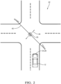
- Fig. 2 illustrates a non-limiting example of an intersection 22 equipped with a traffic-light 20 that is suspended above the intersection 22 by a cable 40 that is attached to poles at each end of the cable 40.
- the traffic-light 20 is moving or swinging with a motion-pattern 34 that can be characterized as swinging diagonally relative to a view-perspective of the host-vehicle 12.
- Figs. 3A and 3B are non-limiting examples of images from the series-of-images 26 that may have been taken by the camera 24 from the perspective illustrated in Fig. 2 while the traffic-light was moving in accordance with the motion-pattern 34 illustrated in Fig. 2 .
- Fig. 3A may be characterized as an instance of the preferred-image 36 because the light-source 38, the green light in this example, is well-directed toward the camera 24, i.e. is pointed almost directly at the camera 24.
- Fig. 3B may be characterized as an instance of a discarded-image 44 from the series-of-images 26 because the light-source is not well-directed toward the camera 24, i.e. is pointed away from the camera 24.
- the motion-pattern 34 is relatively periodic, then there may be multiple instances of the preferred-image 36 shown in Fig. 3A present in the series-of-images 26 that are temporally spaced apart and repeat or reoccur on a periodic basis. It follows that the multiple instances of the preferred-image 36 shown in Fig. 3A may be grouped together for image-processing to determine the light-state 18 based on multiple instances of the preferred-image 36 and thereby determine the light-state 18 with high-confidence.
- the system 10 includes the radar 28, so it follows that the controller 32 is in communication with the camera 24 and the radar 28.
- the controller 32 is configured to determine the motion-pattern 34 of the traffic-light 20 based on the radar-returns 30, and then select the preferred-image 36 from the series-of-images 26 based on the motion-pattern 34 indicated by the radar 28 rather than what might be indicated by the camera 24.
- information from both the camera 24 and the radar 28 may be combined to determine which images of the series-of-images 26 is the preferred-image 36 or are the preferred-images.
- the radar-returns 30 may be analyzed using a variety of techniques known to those in the radar arts to determine the motion-pattern 34 of the traffic-light 20.
- a mid-point of a periodic motion Based on the radar-returns 30, it is determined when a mid-point of a periodic motion occurs, and then designate the image from the series-of-images 26 that temporally coincides with the mid-point as the preferred-image 36.
- the image that corresponds to the mid-point is likely that shown in Fig. 3A , which corresponds to the position of the traffic-light shown in Fig. 2 . That is, it is believed that the mid-point is where the light-source 38 of the traffic-light 20 characterized as being most directed at the camera 24.
- an end-point of the motion-pattern 34 i.e. a point of maximum deflection away from the mid-point, may correspond to Fig.
- the series-of-images 26 would likely include one or more images that is/are the opposite of Fig. 3B . That is, if Fig. 3B is characterized as the traffic-light 20 swinging toward and leftward relative to the camera 24, then there is expected to be an opposite image in the series-of-images that shows the traffic-light 20 as swinging away-from and rightward relative to the camera 24.
- One option is to determine an apparent-size 46 of the light-source 38 in the series-of-images by, for example, counting the number of camera-pixels that detect the light-source 38. It is recognized that counting the number of camera-pixels that detect the light-source 38 in each image of the series-of-images 26 will include tracking the position of where the light-source 38 appears in each of the images.
- counting the number of camera-pixels that detect the light-source 38 in each image of the series-of-images 26 will include tracking the position of where the light-source 38 appears in each of the images.
- the preferred-image 36 is then selected based on which of the images shows or renders the apparent-size 46 characterized as largest in the series-of-images 26. That is, the preferred-image 36 is the image that has the greatest number of camera-pixels that detect the light-source 38. In this example it may not be necessary to determine the particular type of motion, e.g. forward-and-backward, side-to-side, diagonal, oscillatory-rotating, bouncing. The effect of variation of the apparent-size 46 due to swinging if the traffic-light 20 is evident by examining Figs. 3A and 3B .
- controller 32 is configured to determine an apparent-intensity 48 of the light-source 38 in the series-of-images 26.
- the traffic-light 20 is characterized as being most directed at the camera 24, it is expected that the apparent-intensity 48 of the light-source will be the greatest.
- the preferred-image is then selected for having the apparent-intensity 48 characterized as greatest in images of the series-of-images 26.
- the controller 32 is configured to define a bounding-box 50 about each image of the traffic-light 20 in the series-of-images 26, and determine if the traffic-light 20 is moving and/or the motion-pattern 34 based on changes in a box-size of the bounding-box 50 over the series-of-images.
- the box-size may consist of, or include, a box-height, a box-width, a box-area, or any combination thereof. For example, if the motion is forward-and-backward relative to the camera 24, the box-height would vary, but the box-width may be substantially unchanged.
- the selection of the preferred-image 36 may be relatively critical to making a reliable determination of the light-state 18 because of the substantial variation in the apparent-intensity 48.
- side-to-side motion may cause greater variation in box-width and box-area when compared to variation in box-height.
- the selection which image or images are the preferred-image 36 may not be critical to making a reliable determination of the light-state 18.
- the controller 32 may be advantageously further configured to determine when the motion-pattern 34 is such that an other-light 52 ( Fig. 3B ) may be periodically revealed to the camera 24.
- the swinging of the traffic-light 20 causes the red-light that is not directed to the host-vehicle 12 to be revealed to the camera 24.
- the other-light 52 could be a street-light (not shown) or advertisement-light (not shown) that is hidden behind the traffic-signal in Fig. 3A .
- Knowledge that the motion-pattern 34 is such that the other-light 52 may be periodically revealed to the camera 24 may help to prevent confusion about the light-state 18.
- the vehicle-operation block 54 may erroneously elect to apply the brakes rather than continue through the intersection 22.
- the controller 32 may be advantageously further configured to determine a motion-period 56 of the motion-pattern 34, where the motion-period 56 may correspond to the period of oscillation of the swinging-motion of the traffic-light 20. Given the motion-period 56, the controller 32 can predict which of future-images 58 rendered by the camera 24 will be selected as the preferred-image 36. That is, rather than wait until a large number of images in the series-of-images 26 have been rendered and analyzed to select the preferred-image 36, the motion-period 56 can be used to predict when the next instance of an image likely to be an instance of the preferred-image 36 will occur. This will allow the system 10 to more quickly and confidently determine that the light-state 18 has recently changed.
- the system 10 may also include, or have access to via wireless communications, a digital-map 60 that indicates traffic-light-positions of various instances of the traffic-light 20 that the host-vehicle 12 may encounter.
- a traffic-light-detection system (the system 10), a controller 32 for the system 10, and a method of operating the system 10 is provided.
- the system 10 provides for more reliable and quicker determination of the light-state 18 of a traffic-light 20 when the traffic-light 20 is swinging or otherwise moving relative to a host-vehicle 12 equipped with the system 10.
Landscapes
- Engineering & Computer Science (AREA)
- Radar, Positioning & Navigation (AREA)
- Remote Sensing (AREA)
- Physics & Mathematics (AREA)
- General Physics & Mathematics (AREA)
- Computer Networks & Wireless Communication (AREA)
- Electromagnetism (AREA)
- Mechanical Engineering (AREA)
- Multimedia (AREA)
- Theoretical Computer Science (AREA)
- Traffic Control Systems (AREA)
Description
- This disclosure generally relates to a traffic-light-detection system, and more particularly relates to a system that determines a motion-pattern of the traffic-light, and then selects a preferred-image from a series-of-images provided by a camera based on the motion-pattern, where the preferred-image is an image that shows a light-source of the traffic-light characterized as being most directed at the camera.
- It has been observed that camera based vision systems used on automated vehicles often have difficulty detecting the state of a traffic-signal (e.g. red, yellow, green) when the traffic-signal is moving due to, for example, wind.
CA 2 992 080 A1 andEP 3 118 833 A1 both disclose a traffic light recognition device and method - In accordance with one embodiment, a traffic-light-detection system that visually determines a light-state of a traffic-light proximate to an automated vehicle is provided. Said system (10) comprises:
- a camera (24) on the host vehicle (12), said camera (24) configured to render a series of images (26) of a traffic light (20) proximate to the host vehicle (12);
- a radar (28) on the host vehicle (12), said radar (28) configured to detect radar returns (30) reflected by the traffic light (20); and
- a controller (32) in communication with the camera (24) and the radar (28), and configured to: fl determine, based on the radar returns (30), a motion pattern (34) of the traffic light (20) that indicates that the traffic light (20) is moving with a periodic motion;
- select, based on the motion pattern (34) and from the series of images (26), a preferred image (36) that shows a light source (38) of the traffic light (20) when the traffic light (20) is at or near a mid-point of the periodic motion and the light source (38) is most directed at the camera (24); and
- determine the light state (18) of the traffic light (20) based on the preferred image (36).
- Further features and advantages will appear more clearly on a reading of the following detailed description of the preferred embodiment, which is given by way of non-limiting example only and with reference to the accompanying drawings.
- The present invention will now be described, by way of example with reference to the accompanying drawings, in which:
-
Fig. 1 is a diagram of a traffic-light-detection system in accordance with one embodiment; -
Fig. 2 is a top view of an intersection encountered by the system ofFig. 1 in accordance with one embodiment; and -
Figs. 3A and 3B are images from a series-of-images rendered by the system ofFig. 1 in accordance with one embodiment. -
Fig. 1 illustrates a non-limiting example of a traffic-light-detection system 10, hereafter referred to as thesystem 10. In general, thesystem 10 visually determines a light-state 18 (e.g. red, green yellow) of a traffic-light 20 proximate to, e.g. in front of, within fifty meters (50m) for example, an automated vehicle, e.g. a host-vehicle 12. Advantageously, thesystem 10 is able to determine the light-state 18 when the traffic-light 20 is moving, e.g. swinging from a cable 40 (Fig. 2 ) that spans anintersection 22. When the traffic-light 20 is moving, the light emitted by the traffic-light 20 appears to vary from the perspective of the host-vehicle 12 as the direction of the bore-site of light emitted by the traffic-light 20 varies. The apparent variation in apparent-intensity and/or size of the illuminated light (e.g. red, green yellow) on the traffic-light 20 may make it difficult for prior examples of visual traffic light detection systems to determine the light-state 18 of the traffic-light. - As used herein, the term automated vehicle may apply to instances when the host-
vehicle 12 is being operated in an automated-mode 14, i.e. a fully autonomous mode, where a human-operator (not shown) of the host-vehicle 12 may do little more than designate a destination in order to operate the host-vehicle 12. However, full automation is not a requirement. It is contemplated that the teachings presented herein are useful when the host-vehicle 12 is operated in a manual-mode 16 where the degree or level of automation may be little more than providing an audible or visual warning to the human-operator who is generally in control of the steering, accelerator, and brakes of the host-vehicle 12. For example, thesystem 10 may merely warn the human-operator as needed to, for example, avoid 'running' a red-light, i.e. traveling through an intersection 22 (Fig. 2 ) when the traffic-light 20 indicates that the host-vehicle 12 should stop. - In an example , the
system 10 includes acamera 24 on a host-vehicle 12. Thecamera 24 may be a video-camera or a camera capable of taking periodically timed images. Whatever type is used, thecamera 24 needs to be capable to render a series-of-images 26 of the traffic-light 20. Those in the art will recognize that there are a wide variety of commercially available cameras that are suitable for this application. If thecamera 24 is used to determine a motion-pattern 34 of the traffic-light 20 if/when the traffic-light 20 is moving, it is preferable that thecamera 24 has or is characterized by a minimum frame-rate, ten frames-per-second (10 fps) for example. As used herein, the motion-pattern 34 may be a characterization of the type of motion exhibited by the traffic-light 20. For example, the motion-pattern 34 may be characterized as swinging forward-and-backward relative to the host-vehicle 12, side-to-side (i.e. sideways or left-and-right) relative to the host-vehicle 12, swinging diagonally relative to the host-vehicle 12, oscillatory-rotating about a vertical-axis of the traffic-light 20, oscillating vertically along the vertical-axis (bouncing), or any combination thereof. The details of how the motion-pattern 34 is determined and how the series-of-images 26 are analyzed will be explained in more detail later. - The
system 10 according to the invention further includes aradar 28 on the host-vehicle 12. A variety of radar-devices are commercially available for automotive applications that would be suitable to emit a radar-signal toward the traffic-light 20 and detect instances of radar-returns 30 reflected by, and/or returning from, the traffic-light 20. If theradar 28 is used to determine a motion-pattern 34 of the traffic-light 20 when the traffic-light 20 is moving, it is preferable that theradar 28 has or is characterized by a minimum frame-rate, ten frames-per-second (10 fps) for example. - The
system 10 includes acontroller 32 in communication with thecamera 24, and theradar 28 if theradar 28 is provided or included in the configuration of thesystem 10. Thecontroller 32 may include a processor (not specifically shown) such as a microprocessor or other control circuitry such as analog and/or digital control circuitry including an application specific integrated circuit (ASIC) for processing data as should be evident to those in the art. Thecontroller 32 may include memory (not specifically shown), including non-volatile memory, such as electrically erasable programmable read-only memory (EEPROM) for storing one or more routines, thresholds, and captured data. The one or more routines may be executed by the processor to perform steps for determining the motion-pattern 34 and the light-state 18 based on signals received by thecontroller 32 from thecamera 24 and optionally theradar 28 as described herein. - If, in one example not according to the invention, the
system 10 does not include theradar 28, then thecontroller 32 may be configured to determine a motion-pattern 34 of the traffic-light 20 based on the series-of-images 26, and then select a preferred-image 36 from the series-of-images 26. If the traffic-light is not moving, then likely any or all of the images in the series-of-images 26 could be analyzed to determine the light-state 18. Indeed, it is recognized that basing the determination of the light-state 18 on multiple images increases the confidence-level of the determination of the light-state 18. However, when the traffic-light 20 is moving, the position of the illuminated light (red, green, yellow) in each image of the series-of-images 26 likely changes which can make it difficult to have a high confidence-level. - The preferred-
image 36 from the series-of-images 26 corresponds to one or more of the images that shows a light-source 38 (Figs. 3A and 3B ) of the traffic-light 20 as being most directed at thecamera 24 when/while the motion-pattern 34 indicates that the traffic-light 20 is moving. That is, the preferred-image 36 is selected from the series-of-images 26 as being the one or more images that is/are most likely to indicate the light-state 18 with high-confidence. It is recognized that if the motion-pattern 34 is relatively periodic, i.e. relatively predictable, then there may be multiple instances of the preferred-image 36 present in the series-of-images 26 that are temporally spaced apart in accordance with the periodicity of motion or oscillation of the traffic-light 20. -
Fig. 2 illustrates a non-limiting example of anintersection 22 equipped with a traffic-light 20 that is suspended above theintersection 22 by acable 40 that is attached to poles at each end of thecable 40. In this non-limiting example the traffic-light 20 is moving or swinging with a motion-pattern 34 that can be characterized as swinging diagonally relative to a view-perspective of the host-vehicle 12. -
Figs. 3A and 3B are non-limiting examples of images from the series-of-images 26 that may have been taken by thecamera 24 from the perspective illustrated inFig. 2 while the traffic-light was moving in accordance with the motion-pattern 34 illustrated inFig. 2 .Fig. 3A may be characterized as an instance of the preferred-image 36 because the light-source 38, the green light in this example, is well-directed toward thecamera 24, i.e. is pointed almost directly at thecamera 24. By contrast,Fig. 3B may be characterized as an instance of a discarded-image 44 from the series-of-images 26 because the light-source is not well-directed toward thecamera 24, i.e. is pointed away from thecamera 24. If the motion-pattern 34 is relatively periodic, then there may be multiple instances of the preferred-image 36 shown inFig. 3A present in the series-of-images 26 that are temporally spaced apart and repeat or reoccur on a periodic basis. It follows that the multiple instances of the preferred-image 36 shown inFig. 3A may be grouped together for image-processing to determine the light-state 18 based on multiple instances of the preferred-image 36 and thereby determine the light-state 18 with high-confidence. - As previously suggested, the
system 10 according to the invention includes theradar 28, so it follows that thecontroller 32 is in communication with thecamera 24 and theradar 28. In this radar-included embodiment of thesystem 10, thecontroller 32 is configured to determine the motion-pattern 34 of the traffic-light 20 based on the radar-returns 30, and then select the preferred-image 36 from the series-of-images 26 based on the motion-pattern 34 indicated by theradar 28 rather than what might be indicated by thecamera 24. Alternatively, it is contemplated that information from both thecamera 24 and theradar 28 may be combined to determine which images of the series-of-images 26 is the preferred-image 36 or are the preferred-images. The radar-returns 30 may be analyzed using a variety of techniques known to those in the radar arts to determine the motion-pattern 34 of the traffic-light 20. - Based on the radar-
returns 30, it is determined when a mid-point of a periodic motion occurs, and then designate the image from the series-of-images 26 that temporally coincides with the mid-point as the preferred-image 36. In view of the motion-pattern 34 suggested inFig. 2 , the image that corresponds to the mid-point is likely that shown inFig. 3A , which corresponds to the position of the traffic-light shown inFig. 2 . That is, it is believed that the mid-point is where the light-source 38 of the traffic-light 20 characterized as being most directed at thecamera 24. In contrast, an end-point of the motion-pattern 34, i.e. a point of maximum deflection away from the mid-point, may correspond toFig. 3B . It is also contemplated that the series-of-images 26 would likely include one or more images that is/are the opposite ofFig. 3B . That is, ifFig. 3B is characterized as the traffic-light 20 swinging toward and leftward relative to thecamera 24, then there is expected to be an opposite image in the series-of-images that shows the traffic-light 20 as swinging away-from and rightward relative to thecamera 24. - Several examples not according to the invention of how images of the traffic-
light 20 can be subjected to image-processing to help determine the motion-pattern 34 and the light-state 18 will now be discussed. One option is to determine an apparent-size 46 of the light-source 38 in the series-of-images by, for example, counting the number of camera-pixels that detect the light-source 38. It is recognized that counting the number of camera-pixels that detect the light-source 38 in each image of the series-of-images 26 will include tracking the position of where the light-source 38 appears in each of the images. Several algorithms for tracking a moving object in a series-of-images are known and could be used here. The preferred-image 36 is then selected based on which of the images shows or renders the apparent-size 46 characterized as largest in the series-of-images 26. That is, the preferred-image 36 is the image that has the greatest number of camera-pixels that detect the light-source 38. In this example it may not be necessary to determine the particular type of motion, e.g. forward-and-backward, side-to-side, diagonal, oscillatory-rotating, bouncing. The effect of variation of the apparent-size 46 due to swinging if the traffic-light 20 is evident by examiningFigs. 3A and 3B . - Another option not according to the invention is for the
controller 32 to be configured to determine an apparent-intensity 48 of the light-source 38 in the series-of-images 26. When the traffic-light 20 is characterized as being most directed at thecamera 24, it is expected that the apparent-intensity 48 of the light-source will be the greatest. The preferred-image is then selected for having the apparent-intensity 48 characterized as greatest in images of the series-of-images 26. Here again, it may not be necessary to determine the particular type of motion, e.g. forward-and-backward, side-to-side, diagonal, oscillatory-rotating, bouncing. - Another option not according to the invention is for the
controller 32 to be configured to define a bounding-box 50 about each image of the traffic-light 20 in the series-of-images 26, and determine if the traffic-light 20 is moving and/or the motion-pattern 34 based on changes in a box-size of the bounding-box 50 over the series-of-images. As used herein, the box-size may consist of, or include, a box-height, a box-width, a box-area, or any combination thereof. For example, if the motion is forward-and-backward relative to thecamera 24, the box-height would vary, but the box-width may be substantially unchanged. If the motion-pattern 34 is determine to be forward-and-backward, the selection of the preferred-image 36 may be relatively critical to making a reliable determination of the light-state 18 because of the substantial variation in the apparent-intensity 48. In contrast, side-to-side motion may cause greater variation in box-width and box-area when compared to variation in box-height. However, since the apparent-intensity 48 may not change substantially, the selection which image or images are the preferred-image 36 may not be critical to making a reliable determination of the light-state 18. - It is contemplated that the
controller 32 may be advantageously further configured to determine when the motion-pattern 34 is such that an other-light 52 (Fig. 3B ) may be periodically revealed to thecamera 24. As shown inFig. 3 , the swinging of the traffic-light 20 causes the red-light that is not directed to the host-vehicle 12 to be revealed to thecamera 24. Alternatively, the other-light 52 could be a street-light (not shown) or advertisement-light (not shown) that is hidden behind the traffic-signal inFig. 3A . Knowledge that the motion-pattern 34 is such that the other-light 52 may be periodically revealed to thecamera 24 may help to prevent confusion about the light-state 18. For example, if thesystem 10 detects both the light-source 38 as a relatively constant intensity green-light and the other-light 52 as a flashing red-light, the vehicle-operation block 54 (Fig. 1 ) may erroneously elect to apply the brakes rather than continue through theintersection 22. - It is also contemplated that the
controller 32 may be advantageously further configured to determine a motion-period 56 of the motion-pattern 34, where the motion-period 56 may correspond to the period of oscillation of the swinging-motion of the traffic-light 20. Given the motion-period 56, thecontroller 32 can predict which of future-images 58 rendered by thecamera 24 will be selected as the preferred-image 36. That is, rather than wait until a large number of images in the series-of-images 26 have been rendered and analyzed to select the preferred-image 36, the motion-period 56 can be used to predict when the next instance of an image likely to be an instance of the preferred-image 36 will occur. This will allow thesystem 10 to more quickly and confidently determine that the light-state 18 has recently changed. - The
system 10 may also include, or have access to via wireless communications, a digital-map 60 that indicates traffic-light-positions of various instances of the traffic-light 20 that the host-vehicle 12 may encounter. - Accordingly, a traffic-light-detection system (the system 10), a
controller 32 for thesystem 10, and a method of operating thesystem 10 is provided. Thesystem 10 provides for more reliable and quicker determination of the light-state 18 of a traffic-light 20 when the traffic-light 20 is swinging or otherwise moving relative to a host-vehicle 12 equipped with thesystem 10. - While this invention has been described in terms of the preferred embodiments thereof, it is not intended to be so limited, but rather only to the extent set forth in the claims that follow.
Claims (6)
- A traffic-light-detection system (10) that uses radar and imagery to determine a light state (18) of a traffic light (20) proximate to a host vehicle (12), said system (10) comprising:a camera (24) on the host vehicle (12), said camera (24) configured to render a series of images (26) of a traffic light (20) proximate to the host vehicle (12);a radar (28) on the host vehicle (12), said radar (28) configured to detect radar returns (30) reflected by the traffic light (20); anda controller (32) in communication with the camera (24) and the radar (28), and configured to:determine a motion pattern (34) of the traffic light (20) based on the radar returns (30) that indicates that the traffic light (20) is moving with a periodic motion;select, based on the motion pattern (34) and from the series of images (26), a preferred image (36) that shows a light source (38) of the traffic light (20) when the traffic light (20) is at or near a mid-point of the periodic motion and the light source (38) is most directed at the camera (24); anddetermine the light state (18) of the traffic light (20) based on the preferred image (36).
- The system (10) in accordance with claim 1, wherein the controller (32) is further configured to:
determine when the motion pattern (34) is such that another light (52) is periodically revealed to the camera (24). - The system (10) in accordance with claim 1, wherein the controller (32) is further configured to:determine a motion period (56) of the motion pattern (34); andpredict future images (58) rendered by the camera (24) to be selected as the preferred image (36).
- A controller (32) for use in a host vehicle (12), the controller (32) configured to use radar and imagery to determine a light state (18) of a traffic light (20) proximate to the host vehicle (12) by:determining, with a camera (24) in communication with the controller (32) and on the host vehicle (12), a series of images (26) of the traffic light (20) and rendered by the camera (24);determining, with a radar (28) in communication with the controller (32) and on the host vehicle (12), radar returns (30) reflected by the traffic light (20) and detected by the radar (28);determining a motion pattern (34) of the traffic light (20) based on the radar returns (30) that indicates that the traffic light (20) is moving with a periodic motion;selecting, based on the motion pattern (34) and from the series of images (26), a preferred image (36) that shows a light source (38) of the traffic light (20) when the traffic light (20) is at or near a mid-point of the periodic motion and the light source (38) is most directed at the camera (24); anddetermining the light state (18) of the traffic light (20) based on the preferred image (36).
- A non-transitory computer readable medium comprising instructions that, when executed, cause a controller (32) for use in a host vehicle (12) to use radar and imagery to determine a light state (18) of a traffic light (20) proximate to the host vehicle (12) by:determining, with a camera (24) in communication with the controller (32) and on the host vehicle (12), a series of images (26) of the traffic light (20) and rendered by the camera (24);determining, with a radar (28) in communication with the controller (32) and on the host vehicle (12), radar returns (30) reflected by the traffic light (20) and detected by the radar (28);determining a motion pattern (34) of the traffic light (20) based on the radar returns (30) and the series of images (26) that indicates that the traffic light (20) is moving with a periodic motion;selecting, based on the motion pattern (34) and from the series of images (26), a preferred image (36) that shows a light source (38) of the traffic light (20) when the traffic light (20) is at or near a mid-point of the periodic motion and the light source (38) is most directed at the camera (24); anddetermining the light state (18) of the traffic light (20) based on the preferred image (36).
- A method for using radar and imagery to determine a light state (18) of a traffic light (20) proximate to a host vehicle (12, the method comprising:determining, by a controller (32) in communication with a camera (24) on the host vehicle (12), a series of images (26) of the traffic light (20) and rendered by the camera (24);communicating, by the controller (32), with a radar (28) on the host vehicle (12), to determine radar returns (30) reflected by the traffic light (20) and detected by the radar (28);determining, by the controller (32), based on the radar returns (30) and the series of images (26), a motion pattern (34) of the traffic light (20) that indicates that the traffic light (20) is moving with a periodic motion;selecting, by the controller (32), based on the motion pattern (34) and from the series of images (26), a preferred image (36) that shows a light source (38) of the traffic light (20) when the traffic light (20) is at or near a mid-point of the periodic motion and the light source (38) is most directed at the camera (24); anddetermining, by the controller (32), based on the preferred image (36), the light state (18) of the traffic light (20).
Applications Claiming Priority (2)
| Application Number | Priority Date | Filing Date | Title |
|---|---|---|---|
| US15/638,546 US10525903B2 (en) | 2017-06-30 | 2017-06-30 | Moving traffic-light detection system for an automated vehicle |
| PCT/US2018/039940 WO2019006084A1 (en) | 2017-06-30 | 2018-06-28 | Moving traffic-light detection system for an automated vehicle |
Publications (3)
| Publication Number | Publication Date |
|---|---|
| EP3621863A1 EP3621863A1 (en) | 2020-03-18 |
| EP3621863A4 EP3621863A4 (en) | 2021-03-10 |
| EP3621863B1 true EP3621863B1 (en) | 2024-10-16 |
Family
ID=64735276
Family Applications (1)
| Application Number | Title | Priority Date | Filing Date |
|---|---|---|---|
| EP18824682.1A Active EP3621863B1 (en) | 2017-06-30 | 2018-06-28 | Moving traffic-light detection system for an automated vehicle |
Country Status (4)
| Country | Link |
|---|---|
| US (1) | US10525903B2 (en) |
| EP (1) | EP3621863B1 (en) |
| CN (1) | CN110831832B (en) |
| WO (1) | WO2019006084A1 (en) |
Families Citing this family (5)
| Publication number | Priority date | Publication date | Assignee | Title |
|---|---|---|---|---|
| US10852743B2 (en) * | 2018-09-07 | 2020-12-01 | GM Global Technology Operations LLC | Multimodal multi-technique signal fusion system for autonomous vehicle |
| CN111882899B (en) * | 2020-07-24 | 2021-10-22 | 北京小马慧行科技有限公司 | Method, device and system for determining the position of a traffic signal |
| US11527156B2 (en) * | 2020-08-03 | 2022-12-13 | Toyota Research Institute, Inc. | Light emitting component-wise traffic light state, signal, and transition estimator |
| US11681780B2 (en) * | 2020-09-30 | 2023-06-20 | Nissan North America, Inc. | Annotation and mapping for vehicle operation in low-confidence object detection conditions |
| CN116887488B (en) * | 2023-09-07 | 2023-12-12 | 中建照明有限公司 | Traffic lighting control system for urban road and control method thereof |
Family Cites Families (15)
| Publication number | Priority date | Publication date | Assignee | Title |
|---|---|---|---|---|
| JP4507815B2 (en) * | 2004-07-09 | 2010-07-21 | アイシン・エィ・ダブリュ株式会社 | Signal information creating method, signal guide information providing method, and navigation apparatus |
| US20100033571A1 (en) | 2006-09-28 | 2010-02-11 | Pioneer Corporation | Traffic information detector, traffic information detecting method, traffic information detecting program, and recording medium |
| US8559673B2 (en) * | 2010-01-22 | 2013-10-15 | Google Inc. | Traffic signal mapping and detection |
| US8620032B2 (en) | 2011-05-10 | 2013-12-31 | GM Global Technology Operations LLC | System and method for traffic signal detection |
| US8831849B2 (en) * | 2012-02-13 | 2014-09-09 | Toyota Motor Engineering & Manufacturing North America, Inc. | System and method for traffic signal recognition |
| US9145140B2 (en) * | 2012-03-26 | 2015-09-29 | Google Inc. | Robust method for detecting traffic signals and their associated states |
| US8761991B1 (en) | 2012-04-09 | 2014-06-24 | Google Inc. | Use of uncertainty regarding observations of traffic intersections to modify behavior of a vehicle |
| US8793046B2 (en) * | 2012-06-01 | 2014-07-29 | Google Inc. | Inferring state of traffic signal and other aspects of a vehicle's environment based on surrogate data |
| US9881220B2 (en) * | 2013-10-25 | 2018-01-30 | Magna Electronics Inc. | Vehicle vision system utilizing communication system |
| WO2015116950A1 (en) * | 2014-01-30 | 2015-08-06 | Anna Clarke | Systems and methods for lane end recognition |
| EP3118831B1 (en) * | 2014-03-10 | 2019-05-22 | Nissan Motor Co., Ltd | Traffic light detection device and traffic light detection method |
| CN106062851B (en) * | 2014-03-10 | 2018-05-29 | 日产自动车株式会社 | Signal machine detecting device and semaphore detection method |
| US9779314B1 (en) * | 2014-08-21 | 2017-10-03 | Waymo Llc | Vision-based detection and classification of traffic lights |
| CA2992080C (en) * | 2015-07-13 | 2020-01-28 | Nissan Motor Co., Ltd. | Traffic light recognition device and traffic light recognition method |
| US9990548B2 (en) * | 2016-03-09 | 2018-06-05 | Uber Technologies, Inc. | Traffic signal analysis system |
-
2017
- 2017-06-30 US US15/638,546 patent/US10525903B2/en active Active
-
2018
- 2018-06-28 CN CN201880043576.2A patent/CN110831832B/en active Active
- 2018-06-28 EP EP18824682.1A patent/EP3621863B1/en active Active
- 2018-06-28 WO PCT/US2018/039940 patent/WO2019006084A1/en not_active Ceased
Also Published As
| Publication number | Publication date |
|---|---|
| CN110831832B (en) | 2022-12-20 |
| US10525903B2 (en) | 2020-01-07 |
| EP3621863A4 (en) | 2021-03-10 |
| EP3621863A1 (en) | 2020-03-18 |
| CN110831832A (en) | 2020-02-21 |
| WO2019006084A1 (en) | 2019-01-03 |
| US20190001900A1 (en) | 2019-01-03 |
Similar Documents
| Publication | Publication Date | Title |
|---|---|---|
| EP3621863B1 (en) | Moving traffic-light detection system for an automated vehicle | |
| CN102376166B (en) | For identifying the apparatus and method of road signs in motor vehicles | |
| CN107845104B (en) | Method for detecting overtaking vehicle, related processing system, overtaking vehicle detection system and vehicle | |
| JP5962850B2 (en) | Signal recognition device | |
| US10235875B2 (en) | Vehicle communication system for cloud-hosting sensor-data | |
| US9863775B2 (en) | Vehicle localization system | |
| US8452053B2 (en) | Pixel-based texture-rich clear path detection | |
| JP5399027B2 (en) | A device having a system capable of capturing a stereoscopic image to assist driving of an automobile | |
| EP3239738B1 (en) | Prioritized sensor data processing using map information for automated vehicles | |
| CN107408288B (en) | Warning device, warning method, and warning program | |
| KR102387774B1 (en) | Variable range and frame-rate radar operation for automated vehicles | |
| US11488476B2 (en) | Detection system and method | |
| EP3318893A1 (en) | Automated vehicle sensor control system | |
| KR20180117207A (en) | Scenario Recognition System for Automobiles | |
| US11417117B2 (en) | Method and device for detecting lanes, driver assistance system and vehicle | |
| EP3936401A2 (en) | Object position history playback for automated vehicle transition from autonomous-mode to manual-mode | |
| EP3211618A1 (en) | Adjacent lane verification for an automated vehicle | |
| JP2015014916A (en) | Vehicle monitoring system and central device | |
| JP2007164671A (en) | Obstacle approach judgment device and obstacle collision warning system | |
| US11143760B2 (en) | Object-detector configuration based on human-override of automated vehicle control | |
| JP7840363B2 (en) | Driving assistance device, control method for driving assistance device, program, vehicle, and control method for vehicle | |
| JP7253000B2 (en) | Application program, information providing method, and information providing device | |
| EP3796031B1 (en) | A method for reducing the amount of sensor data from a forward-looking vehicle sensor | |
| JP2007072948A (en) | Traffic light lighting state identification method and apparatus | |
| JP2016167173A (en) | Warning device, warning method and warning program |
Legal Events
| Date | Code | Title | Description |
|---|---|---|---|
| STAA | Information on the status of an ep patent application or granted ep patent |
Free format text: STATUS: THE INTERNATIONAL PUBLICATION HAS BEEN MADE |
|
| PUAI | Public reference made under article 153(3) epc to a published international application that has entered the european phase |
Free format text: ORIGINAL CODE: 0009012 |
|
| STAA | Information on the status of an ep patent application or granted ep patent |
Free format text: STATUS: REQUEST FOR EXAMINATION WAS MADE |
|
| 17P | Request for examination filed |
Effective date: 20191211 |
|
| AK | Designated contracting states |
Kind code of ref document: A1 Designated state(s): AL AT BE BG CH CY CZ DE DK EE ES FI FR GB GR HR HU IE IS IT LI LT LU LV MC MK MT NL NO PL PT RO RS SE SI SK SM TR |
|
| AX | Request for extension of the european patent |
Extension state: BA ME |
|
| DAV | Request for validation of the european patent (deleted) | ||
| DAX | Request for extension of the european patent (deleted) | ||
| REG | Reference to a national code |
Ref country code: DE Ref legal event code: R079 Free format text: PREVIOUS MAIN CLASS: B60W0040020000 Ipc: G08G0001096200 Ref country code: DE Ref legal event code: R079 Ref document number: 602018075575 Country of ref document: DE Free format text: PREVIOUS MAIN CLASS: B60W0040020000 Ipc: G08G0001096200 |
|
| A4 | Supplementary search report drawn up and despatched |
Effective date: 20210210 |
|
| RIC1 | Information provided on ipc code assigned before grant |
Ipc: G01S 13/86 20060101ALI20210204BHEP Ipc: G01S 13/931 20200101ALI20210204BHEP Ipc: B60W 30/14 20060101ALI20210204BHEP Ipc: G08G 1/0962 20060101AFI20210204BHEP Ipc: G08G 1/048 20060101ALI20210204BHEP Ipc: B60W 40/02 20060101ALI20210204BHEP Ipc: G01S 7/41 20060101ALI20210204BHEP |
|
| RAP1 | Party data changed (applicant data changed or rights of an application transferred) |
Owner name: APTIV TECHNOLOGIES LIMITED |
|
| STAA | Information on the status of an ep patent application or granted ep patent |
Free format text: STATUS: EXAMINATION IS IN PROGRESS |
|
| 17Q | First examination report despatched |
Effective date: 20220706 |
|
| RAP1 | Party data changed (applicant data changed or rights of an application transferred) |
Owner name: APTIV TECHNOLOGIES AG |
|
| GRAP | Despatch of communication of intention to grant a patent |
Free format text: ORIGINAL CODE: EPIDOSNIGR1 |
|
| STAA | Information on the status of an ep patent application or granted ep patent |
Free format text: STATUS: GRANT OF PATENT IS INTENDED |
|
| INTG | Intention to grant announced |
Effective date: 20240619 |
|
| RIN1 | Information on inventor provided before grant (corrected) |
Inventor name: SZABO, RONALD, J. Inventor name: HILNBRAND, BRIAN, R. Inventor name: LAUR, MICHAEL, H. |
|
| GRAS | Grant fee paid |
Free format text: ORIGINAL CODE: EPIDOSNIGR3 |
|
| P01 | Opt-out of the competence of the unified patent court (upc) registered |
Free format text: CASE NUMBER: APP_44814/2024 Effective date: 20240801 |
|
| GRAA | (expected) grant |
Free format text: ORIGINAL CODE: 0009210 |
|
| STAA | Information on the status of an ep patent application or granted ep patent |
Free format text: STATUS: THE PATENT HAS BEEN GRANTED |
|
| RAP3 | Party data changed (applicant data changed or rights of an application transferred) |
Owner name: APTIV TECHNOLOGIES AG |
|
| AK | Designated contracting states |
Kind code of ref document: B1 Designated state(s): AL AT BE BG CH CY CZ DE DK EE ES FI FR GB GR HR HU IE IS IT LI LT LU LV MC MK MT NL NO PL PT RO RS SE SI SK SM TR |
|
| REG | Reference to a national code |
Ref country code: GB Ref legal event code: FG4D |
|
| REG | Reference to a national code |
Ref country code: CH Ref legal event code: EP Ref country code: DE Ref legal event code: R096 Ref document number: 602018075575 Country of ref document: DE |
|
| REG | Reference to a national code |
Ref country code: IE Ref legal event code: FG4D |
|
| REG | Reference to a national code |
Ref country code: LT Ref legal event code: MG9D |
|
| REG | Reference to a national code |
Ref country code: NL Ref legal event code: MP Effective date: 20241016 |
|
| REG | Reference to a national code |
Ref country code: AT Ref legal event code: MK05 Ref document number: 1733582 Country of ref document: AT Kind code of ref document: T Effective date: 20241016 |
|
| PG25 | Lapsed in a contracting state [announced via postgrant information from national office to epo] |
Ref country code: NL Free format text: LAPSE BECAUSE OF FAILURE TO SUBMIT A TRANSLATION OF THE DESCRIPTION OR TO PAY THE FEE WITHIN THE PRESCRIBED TIME-LIMIT Effective date: 20241016 |
|
| PG25 | Lapsed in a contracting state [announced via postgrant information from national office to epo] |
Ref country code: NL Free format text: LAPSE BECAUSE OF FAILURE TO SUBMIT A TRANSLATION OF THE DESCRIPTION OR TO PAY THE FEE WITHIN THE PRESCRIBED TIME-LIMIT Effective date: 20241016 |
|
| PG25 | Lapsed in a contracting state [announced via postgrant information from national office to epo] |
Ref country code: IS Free format text: LAPSE BECAUSE OF FAILURE TO SUBMIT A TRANSLATION OF THE DESCRIPTION OR TO PAY THE FEE WITHIN THE PRESCRIBED TIME-LIMIT Effective date: 20250216 Ref country code: PT Free format text: LAPSE BECAUSE OF FAILURE TO SUBMIT A TRANSLATION OF THE DESCRIPTION OR TO PAY THE FEE WITHIN THE PRESCRIBED TIME-LIMIT Effective date: 20250217 Ref country code: HR Free format text: LAPSE BECAUSE OF FAILURE TO SUBMIT A TRANSLATION OF THE DESCRIPTION OR TO PAY THE FEE WITHIN THE PRESCRIBED TIME-LIMIT Effective date: 20241016 |
|
| PG25 | Lapsed in a contracting state [announced via postgrant information from national office to epo] |
Ref country code: FI Free format text: LAPSE BECAUSE OF FAILURE TO SUBMIT A TRANSLATION OF THE DESCRIPTION OR TO PAY THE FEE WITHIN THE PRESCRIBED TIME-LIMIT Effective date: 20241016 |
|
| PG25 | Lapsed in a contracting state [announced via postgrant information from national office to epo] |
Ref country code: BG Free format text: LAPSE BECAUSE OF FAILURE TO SUBMIT A TRANSLATION OF THE DESCRIPTION OR TO PAY THE FEE WITHIN THE PRESCRIBED TIME-LIMIT Effective date: 20241016 |
|
| PG25 | Lapsed in a contracting state [announced via postgrant information from national office to epo] |
Ref country code: ES Free format text: LAPSE BECAUSE OF FAILURE TO SUBMIT A TRANSLATION OF THE DESCRIPTION OR TO PAY THE FEE WITHIN THE PRESCRIBED TIME-LIMIT Effective date: 20241016 |
|
| PG25 | Lapsed in a contracting state [announced via postgrant information from national office to epo] |
Ref country code: NO Free format text: LAPSE BECAUSE OF FAILURE TO SUBMIT A TRANSLATION OF THE DESCRIPTION OR TO PAY THE FEE WITHIN THE PRESCRIBED TIME-LIMIT Effective date: 20250116 |
|
| PG25 | Lapsed in a contracting state [announced via postgrant information from national office to epo] |
Ref country code: AT Free format text: LAPSE BECAUSE OF FAILURE TO SUBMIT A TRANSLATION OF THE DESCRIPTION OR TO PAY THE FEE WITHIN THE PRESCRIBED TIME-LIMIT Effective date: 20241016 Ref country code: LV Free format text: LAPSE BECAUSE OF FAILURE TO SUBMIT A TRANSLATION OF THE DESCRIPTION OR TO PAY THE FEE WITHIN THE PRESCRIBED TIME-LIMIT Effective date: 20241016 Ref country code: GR Free format text: LAPSE BECAUSE OF FAILURE TO SUBMIT A TRANSLATION OF THE DESCRIPTION OR TO PAY THE FEE WITHIN THE PRESCRIBED TIME-LIMIT Effective date: 20250117 |
|
| PG25 | Lapsed in a contracting state [announced via postgrant information from national office to epo] |
Ref country code: PL Free format text: LAPSE BECAUSE OF FAILURE TO SUBMIT A TRANSLATION OF THE DESCRIPTION OR TO PAY THE FEE WITHIN THE PRESCRIBED TIME-LIMIT Effective date: 20241016 |
|
| PG25 | Lapsed in a contracting state [announced via postgrant information from national office to epo] |
Ref country code: RS Free format text: LAPSE BECAUSE OF FAILURE TO SUBMIT A TRANSLATION OF THE DESCRIPTION OR TO PAY THE FEE WITHIN THE PRESCRIBED TIME-LIMIT Effective date: 20250116 |
|
| PG25 | Lapsed in a contracting state [announced via postgrant information from national office to epo] |
Ref country code: SM Free format text: LAPSE BECAUSE OF FAILURE TO SUBMIT A TRANSLATION OF THE DESCRIPTION OR TO PAY THE FEE WITHIN THE PRESCRIBED TIME-LIMIT Effective date: 20241016 |
|
| PGFP | Annual fee paid to national office [announced via postgrant information from national office to epo] |
Ref country code: DE Payment date: 20250519 Year of fee payment: 8 |
|
| PG25 | Lapsed in a contracting state [announced via postgrant information from national office to epo] |
Ref country code: DK Free format text: LAPSE BECAUSE OF FAILURE TO SUBMIT A TRANSLATION OF THE DESCRIPTION OR TO PAY THE FEE WITHIN THE PRESCRIBED TIME-LIMIT Effective date: 20241016 |
|
| PGFP | Annual fee paid to national office [announced via postgrant information from national office to epo] |
Ref country code: GB Payment date: 20250611 Year of fee payment: 8 |
|
| REG | Reference to a national code |
Ref country code: DE Ref legal event code: R097 Ref document number: 602018075575 Country of ref document: DE |
|
| PG25 | Lapsed in a contracting state [announced via postgrant information from national office to epo] |
Ref country code: EE Free format text: LAPSE BECAUSE OF FAILURE TO SUBMIT A TRANSLATION OF THE DESCRIPTION OR TO PAY THE FEE WITHIN THE PRESCRIBED TIME-LIMIT Effective date: 20241016 |
|
| PGFP | Annual fee paid to national office [announced via postgrant information from national office to epo] |
Ref country code: FR Payment date: 20250603 Year of fee payment: 8 |
|
| PG25 | Lapsed in a contracting state [announced via postgrant information from national office to epo] |
Ref country code: RO Free format text: LAPSE BECAUSE OF FAILURE TO SUBMIT A TRANSLATION OF THE DESCRIPTION OR TO PAY THE FEE WITHIN THE PRESCRIBED TIME-LIMIT Effective date: 20241016 |
|
| PG25 | Lapsed in a contracting state [announced via postgrant information from national office to epo] |
Ref country code: SK Free format text: LAPSE BECAUSE OF FAILURE TO SUBMIT A TRANSLATION OF THE DESCRIPTION OR TO PAY THE FEE WITHIN THE PRESCRIBED TIME-LIMIT Effective date: 20241016 |
|
| PG25 | Lapsed in a contracting state [announced via postgrant information from national office to epo] |
Ref country code: CZ Free format text: LAPSE BECAUSE OF FAILURE TO SUBMIT A TRANSLATION OF THE DESCRIPTION OR TO PAY THE FEE WITHIN THE PRESCRIBED TIME-LIMIT Effective date: 20241016 |
|
| PG25 | Lapsed in a contracting state [announced via postgrant information from national office to epo] |
Ref country code: IT Free format text: LAPSE BECAUSE OF FAILURE TO SUBMIT A TRANSLATION OF THE DESCRIPTION OR TO PAY THE FEE WITHIN THE PRESCRIBED TIME-LIMIT Effective date: 20241016 |
|
| PLBE | No opposition filed within time limit |
Free format text: ORIGINAL CODE: 0009261 |
|
| STAA | Information on the status of an ep patent application or granted ep patent |
Free format text: STATUS: NO OPPOSITION FILED WITHIN TIME LIMIT |
|
| PG25 | Lapsed in a contracting state [announced via postgrant information from national office to epo] |
Ref country code: SE Free format text: LAPSE BECAUSE OF FAILURE TO SUBMIT A TRANSLATION OF THE DESCRIPTION OR TO PAY THE FEE WITHIN THE PRESCRIBED TIME-LIMIT Effective date: 20241016 |
|
| 26N | No opposition filed |
Effective date: 20250717 |
|
| REG | Reference to a national code |
Ref country code: CH Ref legal event code: H13 Free format text: ST27 STATUS EVENT CODE: U-0-0-H10-H13 (AS PROVIDED BY THE NATIONAL OFFICE) Effective date: 20260127 |
|
| PG25 | Lapsed in a contracting state [announced via postgrant information from national office to epo] |
Ref country code: MC Free format text: LAPSE BECAUSE OF FAILURE TO SUBMIT A TRANSLATION OF THE DESCRIPTION OR TO PAY THE FEE WITHIN THE PRESCRIBED TIME-LIMIT Effective date: 20241016 |
|
| PG25 | Lapsed in a contracting state [announced via postgrant information from national office to epo] |
Ref country code: LU Free format text: LAPSE BECAUSE OF NON-PAYMENT OF DUE FEES Effective date: 20250628 |
|
| REG | Reference to a national code |
Ref country code: BE Ref legal event code: MM Effective date: 20250630 |
|
| PG25 | Lapsed in a contracting state [announced via postgrant information from national office to epo] |
Ref country code: IE Free format text: LAPSE BECAUSE OF NON-PAYMENT OF DUE FEES Effective date: 20250628 |
|
| PG25 | Lapsed in a contracting state [announced via postgrant information from national office to epo] |
Ref country code: BE Free format text: LAPSE BECAUSE OF NON-PAYMENT OF DUE FEES Effective date: 20250630 |
|
| PG25 | Lapsed in a contracting state [announced via postgrant information from national office to epo] |
Ref country code: CH Free format text: LAPSE BECAUSE OF NON-PAYMENT OF DUE FEES Effective date: 20250630 |