EP3621741B1 - Sample rack for sample analysis system - Google Patents
Sample rack for sample analysis system Download PDFInfo
- Publication number
- EP3621741B1 EP3621741B1 EP18799054.4A EP18799054A EP3621741B1 EP 3621741 B1 EP3621741 B1 EP 3621741B1 EP 18799054 A EP18799054 A EP 18799054A EP 3621741 B1 EP3621741 B1 EP 3621741B1
- Authority
- EP
- European Patent Office
- Prior art keywords
- rack
- interior surface
- sample
- along
- handler
- Prior art date
- Legal status (The legal status is an assumption and is not a legal conclusion. Google has not performed a legal analysis and makes no representation as to the accuracy of the status listed.)
- Active
Links
Images






Classifications
-
- G—PHYSICS
- G01—MEASURING; TESTING
- G01N—INVESTIGATING OR ANALYSING MATERIALS BY DETERMINING THEIR CHEMICAL OR PHYSICAL PROPERTIES
- G01N35/00—Automatic analysis not limited to methods or materials provided for in any single one of groups G01N1/00 - G01N33/00; Handling materials therefor
- G01N35/02—Automatic analysis not limited to methods or materials provided for in any single one of groups G01N1/00 - G01N33/00; Handling materials therefor using a plurality of sample containers moved by a conveyor system past one or more treatment or analysis stations
- G01N35/026—Automatic analysis not limited to methods or materials provided for in any single one of groups G01N1/00 - G01N33/00; Handling materials therefor using a plurality of sample containers moved by a conveyor system past one or more treatment or analysis stations having blocks or racks of reaction cells or cuvettes
-
- B—PERFORMING OPERATIONS; TRANSPORTING
- B01—PHYSICAL OR CHEMICAL PROCESSES OR APPARATUS IN GENERAL
- B01L—CHEMICAL OR PHYSICAL LABORATORY APPARATUS FOR GENERAL USE
- B01L9/00—Supporting devices; Holding devices
- B01L9/06—Test-tube stands; Test-tube holders
-
- G—PHYSICS
- G01—MEASURING; TESTING
- G01N—INVESTIGATING OR ANALYSING MATERIALS BY DETERMINING THEIR CHEMICAL OR PHYSICAL PROPERTIES
- G01N35/00—Automatic analysis not limited to methods or materials provided for in any single one of groups G01N1/00 - G01N33/00; Handling materials therefor
- G01N35/02—Automatic analysis not limited to methods or materials provided for in any single one of groups G01N1/00 - G01N33/00; Handling materials therefor using a plurality of sample containers moved by a conveyor system past one or more treatment or analysis stations
- G01N35/04—Details of the conveyor system
-
- B—PERFORMING OPERATIONS; TRANSPORTING
- B65—CONVEYING; PACKING; STORING; HANDLING THIN OR FILAMENTARY MATERIAL
- B65G—TRANSPORT OR STORAGE DEVICES, e.g. CONVEYORS FOR LOADING OR TIPPING, SHOP CONVEYOR SYSTEMS OR PNEUMATIC TUBE CONVEYORS
- B65G2201/00—Indexing codes relating to handling devices, e.g. conveyors, characterised by the type of product or load being conveyed or handled
- B65G2201/02—Articles
- B65G2201/0235—Containers
- B65G2201/0244—Bottles
-
- B—PERFORMING OPERATIONS; TRANSPORTING
- B65—CONVEYING; PACKING; STORING; HANDLING THIN OR FILAMENTARY MATERIAL
- B65G—TRANSPORT OR STORAGE DEVICES, e.g. CONVEYORS FOR LOADING OR TIPPING, SHOP CONVEYOR SYSTEMS OR PNEUMATIC TUBE CONVEYORS
- B65G2201/00—Indexing codes relating to handling devices, e.g. conveyors, characterised by the type of product or load being conveyed or handled
- B65G2201/02—Articles
- B65G2201/0235—Containers
- B65G2201/0261—Puck as article support
-
- B—PERFORMING OPERATIONS; TRANSPORTING
- B65—CONVEYING; PACKING; STORING; HANDLING THIN OR FILAMENTARY MATERIAL
- B65G—TRANSPORT OR STORAGE DEVICES, e.g. CONVEYORS FOR LOADING OR TIPPING, SHOP CONVEYOR SYSTEMS OR PNEUMATIC TUBE CONVEYORS
- B65G47/00—Article or material-handling devices associated with conveyors; Methods employing such devices
- B65G47/22—Devices influencing the relative position or the attitude of articles during transit by conveyors
- B65G47/24—Devices influencing the relative position or the attitude of articles during transit by conveyors orientating the articles
- B65G47/244—Devices influencing the relative position or the attitude of articles during transit by conveyors orientating the articles by turning them about an axis substantially perpendicular to the conveying plane
-
- G—PHYSICS
- G01—MEASURING; TESTING
- G01N—INVESTIGATING OR ANALYSING MATERIALS BY DETERMINING THEIR CHEMICAL OR PHYSICAL PROPERTIES
- G01N35/00—Automatic analysis not limited to methods or materials provided for in any single one of groups G01N1/00 - G01N33/00; Handling materials therefor
- G01N35/02—Automatic analysis not limited to methods or materials provided for in any single one of groups G01N1/00 - G01N33/00; Handling materials therefor using a plurality of sample containers moved by a conveyor system past one or more treatment or analysis stations
- G01N35/04—Details of the conveyor system
- G01N2035/0401—Sample carriers, cuvettes or reaction vessels
- G01N2035/0412—Block or rack elements with a single row of samples
- G01N2035/0415—Block or rack elements with a single row of samples moving in two dimensions in a horizontal plane
-
- G—PHYSICS
- G01—MEASURING; TESTING
- G01N—INVESTIGATING OR ANALYSING MATERIALS BY DETERMINING THEIR CHEMICAL OR PHYSICAL PROPERTIES
- G01N35/00—Automatic analysis not limited to methods or materials provided for in any single one of groups G01N1/00 - G01N33/00; Handling materials therefor
- G01N35/02—Automatic analysis not limited to methods or materials provided for in any single one of groups G01N1/00 - G01N33/00; Handling materials therefor using a plurality of sample containers moved by a conveyor system past one or more treatment or analysis stations
- G01N35/04—Details of the conveyor system
- G01N2035/046—General conveyor features
Definitions
- the present disclosure relates to a sample rack for a sample analysis system.
- Diagnostic methods may include testing a sample to measure sample properties and/or to detect substances of interest that may be present in the sample.
- urine chemistry and sediments are commonly analyzed.
- the liquid sample usually contains one or more analytes/particles of interest.
- analytes/particles of interest For urine chemistry analysis, the presence and concentrations of the analytes of interest in the sample are determinable by an analysis of the color changes undergone by the reagent pads that have been submerged in the liquid sample.
- urine sediment analysis the presence and concentrations of the particles of interest are measured by microscopic image analysis. These analyses may be donemanually or using automated test device.
- Samples may be presented to the test device via a sample rack that holds multiple sample collection units, e.g. sample tubes.
- Sample racks capable of holding a plurality of sample tubes or containers are known in the prior art (e.g. from US patent 6,065,617 and US patent application 2010/0166606 A1 ).
- a conveyor system is used to present the sample rack, containing the sample collection units, to the test device by moving sample racks horizontally along a travel path that has a U-shape.
- the U-shaped travel path has a first leg that can stage multiple sample racks, a lateral portion adjacent the test device, and a second leg that is parallel to the first leg.
- US 7,407,627 B1 discloses an automatic analytical apparatus comprising a sample transport arrangement for transporting sample racks from a rack input device of a rack supply unit to a rotatable sample rack carrier.
- the invention of the disclosure is a rack adapted to engage a rack handler and to carry a sample collection unit.
- the rack includes a rack body.
- the rack body has a bottom, a top opposite the bottom, and a receptacle that extends from the top toward the bottom.
- the receptacle is sized to receive the sample collection unit.
- the rack body has a first interior surface that extends from the bottom toward the top and a second interior surface that extends from the bottom toward the top.
- the second interior surface is opposite to the first interior surface so as to at least partially define a slot along the bottom.
- the rack body also includes an interference groove in the slot along at least one of the first interior surface and the second interior surface.
- the first interior surface and the second interior surface have portions that are angularly offset with respect to each other so as to define the interference groove.
- the slot and the interference groove are sized to engage a portion of the rack handler.
- the portion of the rack handler is a rotation assembly.
- the rack includes further a protrusion which engages with the interference groove for rotating the sample rack.
- the system comprises a rack handler and a rack having a rack body.
- the rack body has a bottom, a top opposite the bottom, and a receptacle that extends from the top toward the bottom.
- the receptacle is sized to receive the sample collection unit.
- the rack body has a first interior surface that extends from the bottom toward the top and a second interior surface that extends from the bottom toward the top.
- the second interior surface is opposite to the first interior surface so as to at least partially define a slot along the bottom.
- the rack body also includes an interference groove in the slot along at least one of the first interior surface and the second interior surface. The slot and the interference groove are sized to engage a portion of the rack handler.
- inventions of the present disclosure include a sample analysis system 1 for analyzing samples.
- the sample analysis system 1 includes one or more test devices 10, 20, a computing device 30 electronically coupled to the test devices 10, 20, a sample rack handler 100, and multiple sample racks 200.
- the sample racks 200 hold sample collection units 50.
- Each sample collection unit 50 may contain a sample for testing.
- the computing device 30 may be used to control operation of the sample analysis system 1.
- the computing device 30 may include typical components of a computer, including a memory, one or more processors, a user interface, input/output ports, and various software applications used to run the sample analysis system 1.
- the computing device 30 may be a separate component as illustrated. Alternatively, the computing device 30 may be integrated with either or both test devices 10, 20.
- the sample analysis system 1 may include at least one test device, e.g. a first test device 10 and a second device 20.
- the first and second test devices 10 and 20 are designed to analyze analytes of interest in the sample.
- the first test device 10 is configured to analyze the sample contained in the sample collection unit 50.
- the test device 10 may include a device, such as a color imager, that determines the color of the sample applied to one or more of the reagent pads on a test strip.
- Other types of systems may include a spectrophotometer that determines color changes based on reflectance readings, or digital microscope that uses special algorithm to classify particles based the size, shape and texture.
- Test devices 10 may employ a variety of area array detection read-heads utilizing CCD (charge-coupled device), CID (charge-injection device) or PMOS (P-type metal-oxide-semiconductor) detection structures for detecting color changes to the reagent pads. The color changes can be used to determine the presence of analytes of interest. While a spectrophotometer is described above, other systems for testing a sample may be used in the sample analysis system 1 and the present disclosure is not strictly limited to optical based systems.
- CCD charge-coupled device
- CID charge-injection device
- PMOS P-type metal-oxide-semiconductor
- test devices 10 and 20 may be used for robust evaluations of samples. If the data obtained by the first test device 10 indicates a need for further analysis, the rack handler 100 conveys the sample rack 200 and sample collection units 50 to the second test device 20. Further tests are performed on the samples by the second test device 20.
- the inventive concepts as described herein are not strictly limited to analysis systems that include two or more separate test devices.
- the second test device 20 includes a housing 22 and an analyzer (not shown) contained in the housing 22.
- the housing 22 is coupled to the rack handler 100 and includes front panel near where the rack handler 100 is coupled to the second test device 20.
- the front panel 24 includes a portal 26 through which the sample rack 200 travels if it is determined that a sample in the sample rack 200 needs further analysis by the second test device 20.
- the sample rack handler 100 includes a base 118, a transport system 120, and a rotation assembly 150.
- the sample rack handler 100 defines a travel path P along which the transport system 120 guides the sample racks 200.
- the sample rack handler 100 includes an input staging region 102 where sample racks 200 to be tested may be staged, a lateral portion 104, a rotation region 106, a travel region 108, and an output staging region 110 where sample racks 200 may be collected once testing is complete.
- the rack handler 100 as illustrated includes a serpentine travel path P. It should be appreciated that the inventive concepts disclosed herein are not limited to the specific travel path shown. Accordingly, the sample rack handler 100 as disclosed herein may be used with any type of sample analysis system that needs to move a sample rack from one location to another location and may need to change the orientation of the sample rack from one orientation to another orientation.
- the transport system 120 can hold and convey multiple sample racks 200 along the travel path P from the input staging region 102 to the first test device 10, from the first test device 10 to the second test device 20, and further into the output staging region 110.
- the transport system 120 may include guide elements 130, one or more belts 132, and motors (not shown) that are used to advance the sample racks 200 along the travel path P.
- guide elements 130 may comprise movable tabs that travel along the path P and can push the sample racks 200 along the travel path P into the desired position.
- the transport system 120 may be electronically coupled to a control system 300 (See Figure 4 ) that will be described further below.
- the rack handler 100 includes a rotation assembly 150 that is used to change the orientation of the sample rack 200 along the travel path P.
- the rotation assembly 150 includes an engagement element 160 that extends along a vertical axis 4.
- the engagement element 160 has a base 162 and a protrusion 164 that projects upward from the base 162.
- the protrusion 164 can engage the sample rack as discussed further below.
- the rotation assembly 150 also includes a motor 330 coupled to the engagement element 160 and operable to cause the engagement element 160 to rotate about the vertical axis 4. Rotation of the engagement element 160 about the vertical axis 4 causes the sample rack to rotate about the vertical axis V when the engagement element 160 is engaged with the sample rack 200.
- FIGS 3A-3C illustrate an exemplary engagement element 160.
- the engagement element 160 may be any structure or device that can selectively engage and/or be coupled to a sample rack 200.
- the engagement element includes the base 162, which forms a body 166 having an upper surface 168, a lower surface 170 opposite the upper surface 168 along the vertical axis 4, and a central recess 172 that extends from the lower surface 170 into the base 162 along the vertical axis 4.
- a shaft 174 extends from the motor 330 and into the central recess 172 of the engagement element 160 to rotationally couple the engagement element 160 to the motor 330.
- the motor 330 may be electrically coupled to a controller 310 in the control system 300 as further explained below and illustrated in Figure 4 .
- the base 162 is a structure that supports the protrusion 164 and provides enables coupling the motor 330 to the engagement element 160 via the shaft 174. Any particular structure may be used to form the base 162.
- the base 162 and protrusion 164 may be monolithic. Alternatively, the base 162 and the protrusion 164 may be separate components that are coupled together during manufacture of the rotation assembly 150.
- the protrusion 164 may be designed to engage with sample rack 200. As shown, the protrusion projects 164 from the base along the vertical axis 4 and may define an elongated tab that is sized to fit within the slot 270 ( Fig. 8 ) of the sample rack.
- the protrusion 164 defines a first end 180 and a second end 182 that is opposite the first end 180 along a first axis 6 that is perpendicular to the vertical axis 4.
- the protrusion 164 also includes a first side 184 that extends between the first and second ends 180, 182, and a second side 186 that extends between the first and second ends 180, 182.
- the first and second sides 184 and 186 are shown disposed on opposite sides of the vertical axis 4.
- the protrusion 164 defines a length L that extends from the first end 180 to the second end 182 along a first axis 6 that intersects and is perpendicular to the vertical axis 4, and a width W that extends from the first side 184 to the second side 164 along a second axis 8 that intersects and is perpendicular to the first axis 6 and the vertical axis 4.
- the length L of the protrusion 164 is greater than the width W of the protrusion 164.
- the protrusion 164 also includes a top surface 188 and a height H that extends from an upper surface 168 of the base 162 to the top surface 188 along the vertical axis 4. In one example, the height H is less than the length L.
- the engagement element 160 may comprise a protrusion 164 with a configuration other than what is illustrated and described above.
- the protrusion 164 may have any polygonal cross-sectional shape that is defined perpendicular the vertical axis 4.
- the protrusion can have cross-sectional shape that is a square, a triangle, a pentagon, a hexagon, an octagon, or other shapes that have three or more sides.
- the engagement element 160 may comprise a plurality of protrusions (not shown) that are spaced apart and aligned with each other along an axis that intersects and is perpendicular to the vertical axis 4.
- the engagement element 160 may include a first protrusion and a second protrusion that is spaced apart from and aligned with the first protrusion along the axis.
- the first and second protrusions are positioned to engage the slot of the sample rack.
- the rotation assembly 150 is operable to cause the engagement element 160 to rotate about the vertical axis 4 to cause the sample rack 200 to pivot.
- the engagement element 160 is rotatable in a first rotational direction R1 and a second rotational direction R2 that is opposite the first rotational direction R1.
- the rotational direction of the engagement element 160 is based, in part, on its engagement with the sample rack 200 and the orientation of the sample rack 200. How the rotation assembly 150 operates to pivot the sample rack from the first orientation to a second orientation is described in further detail below.
- FIG 4 illustrates a control system 300 used to control operation of at least the rack handler 100.
- the control system 300 includes one or more controllers 310, at least one motor 330 that is electrically coupled to the controller 310, and a plurality of sensors electrically coupled to the controller 310.
- the controller 310 includes at least one processing unit 312, a memory unit 314, and communications unit 316.
- the sensors are positioned along various portions of the travel path P and may be configured to detect the presence of a sample rack 200 proximate to a particular sensor.
- the control system includes a first sensor 352, a second sensor 354 and optionally one or more additional sensors.
- the sensors 352 and 354 obtain sensor data concerning a position of the sample rack that is transmitted electronically to the controller 310 through the communications unit 314.
- the sensors 352 and 354 are position sensors, such as Hall Effect sensors. However, other sensors could be used to determine rack 200 position.
- the controller 310 causes the motor 330 to operate based on the position data of the sample rack 200 obtained via the sensors described above. Operation of the rack handler 100 to move the sample racks 200 along the travel path P will be described further below.
- FIGS. 5-9 illustrate a sample rack 200 adapted to engage the rack handler 100.
- the sample rack 200 includes a rack body 202, a bottom 205, and a top 203 spaced from the bottom 205 along a vertical direction V.
- the rack body 202 further defines a top surface 204 at the top 203 and a bottom surface 206 at the bottom 205 that opposite the top surface 204 along the vertical direction V.
- the rack body 202 further includes a first side 208, a second side 210 opposite the first side 208 along a transverse direction T, a first end 212, and a second end 214 opposite the first end 212 along a longitudinal direction L.
- the longitudinal direction L is perpendicular to the vertical direction V and to the transverse direction T.
- the rack body 202 further includes a base portion 220 that defines the bottom surface 206, and a rack portion 230 that extends upwardly from the base portion 220 along the vertical direction V.
- the rack portion 230 defines the top surface 204.
- the rack body 202 includes at least one receptacle 240 (such as a plurality of receptacles).
- the receptacle 240 is sized and shaped to hold a sample collection unit 50.
- the rack 200 includes 10 separate receptacles 240.
- the rack 200 may include less than ten receptacles, such as one receptacle 240, or more than ten receptacles 240.
- the rack 200 is configured to engage a portion of the rack handler 100, such as, for example, the rotation assembly 150.
- the rack body 202 includes a first interior surface 250 that extends from the bottom 205 toward the top 203 along the vertical direction, and a second interior surface 260 that extends from the bottom 205 toward the top 203 along the vertical direction V.
- the first interior surface 250 and the second interior surface 260 may be referred to as first wall 250 and a second wall 260, respectively.
- the second interior surface 260 is opposite to the first interior surface 250 so as to at least partially define a slot 270 along the bottom 205 of the sample rack 200.
- the sample rack 200 includes at least one interference groove 252, 262 in either of both of the first interior surface 250 and the second interior surface 260.
- the sample rack 200 includes a first interference groove 252 formed in the first interior surface 250 and a second interference groove 262 formed in the second interior surface 260.
- the rack may include a single interference groove.
- the rack 200 includes a single slot 270 along the bottom 205 of the sample rack 200.
- the rack may include a plurality of slots along the bottom 205 for receiving a portion of the rack handler 100.
- the rack 200 may have a first slot 270 and a second slot (not shown) that is similar to the first slot. Multiple slots would allow the rack 200 to be inserted into the rack handler in either orientation and still be rotatable by the rotation assembly 150.
- the first interior surface 250 has a first portion 254, a second portion 256, and a third portion 258.
- the first portion 254 and second portion 256 are angularly offset with respect to each other so as to define the first interference groove 252.
- the first portion 254 and the second portion 256 may intersect to define a first angle ⁇ 1 therebetween.
- the first angle ⁇ 1 is less than 180 degrees.
- the first angle ⁇ 1 is between 45 degrees and 135 degrees.
- the first angle ⁇ 1 may not be limited to this stated range.
- the first and second portions 254 and 256 may not intersect.
- the first and second portions 254 and 256 may not intersect and may be substantially parallel to each other to define the interference groove.
- the third portion 258 is angularly offset from the first and second portions 254 and 256.
- the second interior surface 260 includes a first portion 264, a second portion 266, and a third portion 268.
- the first portion 264 and a second portion 266 are angularly offset with respect to each other so as to define the second interference groove 262.
- the first portion 264 and the second portion 266 may intersect to define a second angle ⁇ 2 therebetween.
- the first angle ⁇ 2 is less than 180 degrees.
- the second angle ⁇ 2 is between 45 degrees and 135 degrees.
- the second angle ⁇ 2 may not be limited to this stated range. However, in alternative embodiments, the first and second portions 264 and 266 may not intersect.
- first and second portions 264 and 266 may not intersect and may be substantially parallel to each other to define the interference groove.
- the third portion 268 is angularly offset from the first and second portions 264 and 266.
- the third portion 258 of the first interior surface 250 is substantially parallel to the third portion 268 of the second interior surface 260.
- the third portion 258 of the first interior surface 250 may not be specifically parallel to the third portion 268 of the second interior surface 260.
- the slot 270 includes a first wall 250 and a second wall 260 that is substantially a parallel to the first wall 250. As illustrated, the first and second walls 250, 260 are arranged on opposing sides of a first axis A1. The first axis A1 can be described as the center line of the slot.
- the first wall 250 has at least one indentation 252 and the second wall 260 has at least one indentation 262.
- the indentation 252 in the first wall 250 has first and second portions254 and 256.
- the indentation 262 in the second wall 260 has first and second portions 264 and 266.
- each indentation 252, 262 can be oriented along a second axis A2 which is offset from the first axis A1.
- the respective second portions 256, 266 of each indentation 254, 264 can be oriented along a third axis A3 which is offset from the first axis A1 and second axis A2.
- the distance between the second portions 256, 266 of the indentations 252, 262 generally corresponds to the size of the engagement element 160.
- the slot 270 extends from the first side 208 to the second side 210 and is located primarily in the base portion 220 of the sample rack 200. In addition, the slot 270 is closer to the first end 212 than to the second end 214. In other words, the slot 270 may be spaced a first distance D1 from the first end 212 and a second distance D2 from the second end 214 but the first distance D1 is less than the second distance D2. The location of the slot 270 toward the first end 212 can facilitate engagement with the rack handler 100 and rotation by the rack handler 100 as shown and further described below.
- one end of the slot 270 may be widened in order to allow for easy insertion of the engagement element 160 when the sample rack is not perfectly aligned with the rotation assembly 150.
- both ends of the slot 270 could be widened as well.
- the sample rack 200 includes a recess 290 that is adapted to engage the transport system 120 of the rack handler 100.
- the rack body 202 defines a recess 290 that extends into the second end 214 of the rack body 202 along the longitudinal direction L.
- the recess 290 extends from the first side 208 to the second side 210.
- the recess 290 is shown spaced slightly above the bottom surface 206 along the vertical direction V in order to engage a guide element 130.
- the recess 290 engages a guide element along a substantially portion of the travel path P through the rack handler 100 and helps to stabilize the rack 200 during transport along the travel path P.
- the engagement element 160 is designed to engage with a portion of the sample rack 200 to move the sample rack 200 from a first orientation where the side 210 faces the test device 20 into a second orientation that is rotationally different than the first orientation.
- the sample rack 200 may be moved over the rotation assembly 150 so that the protrusion 164 slides within the slot 270.
- the sides of the protrusion 164 are generally parallel to the first and second interior surfaces 250 and 260 of the sample rack 200.
- the controller 310 can cause the engagement element 160 to rotate in the slot 270 of the sample rack 200 a first rotational distance R1 to engage the at least one interference groove 252, 262 in the sample rack 200.
- the first and second ends 180 and 182 of the protrusion 164 can engage with and abut the first and second interference grooves 252 and 262, respectively.
- the engagement element rotates a second rotational distance R2 (not shown) to rotate the sample rack 200 from the first orientation (e.g. see Figure 17 ) into the second orientation (e.g. Figure 19 ).
- the engagement element 160 rotates a first rotational distance to fully engage the sample rack 200 and rotates a second rotational distance to cause the sample rack 200 to rotate into the second orientation. In this manner, the second rotational distance is greater than the first rotation distance.
- the engagement element 160 can disengage from the sample rack 200.
- the engagement element 160 can rotate in a second rotational direction R2 that is opposite to the first rotational direction R1 in order move the protrusion 164 out of engagement with the interference groove 252, 262.
- the protrusion 164 is aligned with the slot 270, similar to that which is shown in Figure 12 , the sample rack 200 can be translated along the travel path P by the transport system 120.
- the transport system 120 advances the sample rack 200 from the input staging region 102 in a first direction 112 to the first test device 10 until the sample rack 200 is positioned in the lateral portion 104.
- the transport system 120 can advance the sample rack 200 in a lateral direction 116 into a testing position proximate an analyzer (not shown) in the test device 10. Once testing is complete, the transport system 120 advances the sample rack 200 further along the lateral portion 104 until the sample rack is aligned with the rotation region 106, as shown in Figure 16 .
- the transport system 120 via a controller 310, advances the sample rack 200 over the engagement element 160.
- the first sensor 352 determines when the sample rack 200 is engaged with the engagement element 160 of the rack handler in the first orientation (similar to the position shown in Figures 10 , 12 , & 17 ).
- the controller 310 causes the motor 330 to begin rotation of the engagement element 160.
- the engagement element 160 then rotates into engagement with the interference groove 252, 262 of the slot 270, as described above (and shown in Figures 11 and 13 ).
- the controller 310 can then cause the transport system 120 to advance the sample rack 200 along a direction 116 until the sample rack 200 has disengaged from the engagement element 160 completely. If the sample rack 200 is disengaged, the transport system 120 may be used to advance the sample rack along the direction 115 in travel region 108.
- the longitudinal end 212 of the sample rack may face the first test device 10 (or second test device if present).
- the sample rack 200 is oriented to be inserted into the portal 26 of the second test device 20.
- the transport system 120 translates the sample rack 200 in the second direction 116. Once the sample rack 200 is positioned adjacent to portal 26, guide elements (not shown) pull the sample rack 200 along the first direction 112 into the housing 22 of the second test device 20 so that the sample(s) can be further analyzed, as shown in Figure 1 .
- the sample rack 200 is pushed out onto the travel path P.
- the transport system 120 advances the sample rack 200 into the output staging region 110.
Landscapes
- Chemical & Material Sciences (AREA)
- Health & Medical Sciences (AREA)
- Biochemistry (AREA)
- Physics & Mathematics (AREA)
- Life Sciences & Earth Sciences (AREA)
- Analytical Chemistry (AREA)
- Chemical Kinetics & Catalysis (AREA)
- General Health & Medical Sciences (AREA)
- General Physics & Mathematics (AREA)
- Immunology (AREA)
- Pathology (AREA)
- Clinical Laboratory Science (AREA)
- Automatic Analysis And Handling Materials Therefor (AREA)
Description
- The present disclosure relates to a sample rack for a sample analysis system.
- Diagnostic methods may include testing a sample to measure sample properties and/or to detect substances of interest that may be present in the sample. In the field of urinalysis, urine chemistry and sediments are commonly analyzed. The liquid sample usually contains one or more analytes/particles of interest. For urine chemistry analysis, the presence and concentrations of the analytes of interest in the sample are determinable by an analysis of the color changes undergone by the reagent pads that have been submerged in the liquid sample. For urine sediment analysis, the presence and concentrations of the particles of interest are measured by microscopic image analysis. These analyses may be donemanually or using automated test device.
- Samples may be presented to the test device via a sample rack that holds multiple sample collection units, e.g. sample tubes. Sample racks capable of holding a plurality of sample tubes or containers are known in the prior art (e.g. from
US patent 6,065,617 andUS patent application 2010/0166606 A1 ). Typically, a conveyor system is used to present the sample rack, containing the sample collection units, to the test device by moving sample racks horizontally along a travel path that has a U-shape. The U-shaped travel path has a first leg that can stage multiple sample racks, a lateral portion adjacent the test device, and a second leg that is parallel to the first leg. The sample racks are staged in the first leg of the travel path and the conveyor system moves the sample rack in a first direction to the lateral portion that is adjacent to the test device. Then, the sample rack is translated laterally into a test position adjacent the test device along that lateral portion. When the test procedure is complete, the conveyor system moves the sample rack again laterally. After the last lateral movement of the sample rack, the conveyor system then moves the sample rack in a second direction along the second leg into an additional staging region.US 7,407,627 B1 discloses an automatic analytical apparatus comprising a sample transport arrangement for transporting sample racks from a rack input device of a rack supply unit to a rotatable sample rack carrier. - The invention of the disclosure is a rack adapted to engage a rack handler and to carry a sample collection unit. The rack includes a rack body. The rack body has a bottom, a top opposite the bottom, and a receptacle that extends from the top toward the bottom. The receptacle is sized to receive the sample collection unit. The rack body has a first interior surface that extends from the bottom toward the top and a second interior surface that extends from the bottom toward the top. The second interior surface is opposite to the first interior surface so as to at least partially define a slot along the bottom. The rack body also includes an interference groove in the slot along at least one of the first interior surface and the second interior surface. The first interior surface and the second interior surface have portions that are angularly offset with respect to each other so as to define the interference groove. The slot and the interference groove are sized to engage a portion of the rack handler. The portion of the rack handler is a rotation assembly. The rack includes further a protrusion which engages with the interference groove for rotating the sample rack.
- One embodiment of the present disclosure is a sample analysis system for analyzing a sample. The system comprises a rack handler and a rack having a rack body. The rack body has a bottom, a top opposite the bottom, and a receptacle that extends from the top toward the bottom. The receptacle is sized to receive the sample collection unit. The rack body has a first interior surface that extends from the bottom toward the top and a second interior surface that extends from the bottom toward the top. The second interior surface is opposite to the first interior surface so as to at least partially define a slot along the bottom. The rack body also includes an interference groove in the slot along at least one of the first interior surface and the second interior surface. The slot and the interference groove are sized to engage a portion of the rack handler.
- The foregoing summary, as well as the following detailed description of illustrative embodiments of the present application, will be better understood when read in conjunction with the appended drawings. For the purposes of illustrating the present application, there is shown in the drawings illustrative embodiments of the disclosure. It should be understood, however, that the application is not limited to the precise arrangements and instrumentalities shown. In the drawings:
-
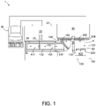
FIG. 1 is a schematic plan view of a sample analysis system according to an embodiment of the present disclosure; -
FIG. 2A is a perspective view of a rack handler and sample rack used in the system shown inFIG. 1 ; -
FIG. 2B is a top plan view of the rack handler shown inFIG. 2A ; -
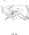
FIG. 3A is a top perspective view of a portion of the rack handler shown inFIG. 2A ; -
FIG. 3B is a top perspective view of a portion of a rotation assembly shown inFIG. 3A ; -
FIG. 3C is a side view the portion of a rotation assembly shown inFIG. 3B ; -
FIG. 4 is a schematic diagram illustrating a control system used in the rack handler shown inFIG. 2A ; -
FIG. 5 is a perspective view of the sample rack used in the system illustrated inFIG. 1 ; -
FIG. 6 is a rear elevation view of the sample rack illustrated inFIG. 5 ; -
FIG. 7 is a bottom plan view of the sample rack illustrated inFIG. 5 ; -
FIG. 8 is a detailed view of a portion of the bottom of the sample rack illustrated inFIG. 5 ; -
FIG. 9 is a detailed perspective view of a portion of the bottom of the sample rack illustrated inFIG. 5 ; -
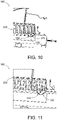
FIG. 10 is a perspective view of a portion of the rack handler inFIG. 2A , illustrating the sample rack engaged with a rotation assembly in a first configuration; -
FIG. 11 is a perspective view of a portion of the rack handler inFIG. 2A , illustrating the sample rack engaged with a rotation assembly in a second, engaged configuration; -
FIG. 12 is a cross-sectional view of a portion of the rack handler taken along line A-A inFIG. 10 , illustrating the sample rack engaged with the rotation assembly in the first configuration; -
FIG. 13 is a sectional view of a portion of the rack handler taken along line B-B inFIG. 11 , illustrating the sample rack engaged with a rotation assembly in the second, engaged configuration; -
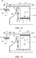
FIG. 14 is a plan view of the rack handler with a sample rack shown in an input staging region; -
FIG. 15 is a plan view of the rack handler with the sample rack shown adjacent to test device prior to the sample rack being staged in a testing position; -
FIG. 16 is a plan view of the rack handler with the sample rack shown adjacent to test device after the sample rack is moved out of the testing position; -
FIG. 17 is a plan view of the rack handler with the sample rack shown advanced into engagement with the rotation assembly and in the first orientation; -
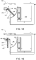
FIG. 18 is a plan view of the rack handler showing the sample rack rotated into a different orientation; -
FIG. 19 is a plan view of the rack handler with the sample rack shown in a completed turn and engaged with the rotation assembly and in a second orientation; and -
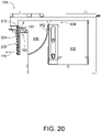
FIG. 20 is a plan view of the rack handler with the sample rack shown advanced off of the rotation assembly and positioned for transport to another test device. - Referring to
Figure 1 , embodiments of the present disclosure include a sample analysis system 1 for analyzing samples. The sample analysis system 1 includes one ormore test devices computing device 30 electronically coupled to thetest devices sample rack handler 100, and multiple sample racks 200. The sample racks 200, holdsample collection units 50. Eachsample collection unit 50 may contain a sample for testing. - The
computing device 30 may be used to control operation of the sample analysis system 1. Thecomputing device 30 may include typical components of a computer, including a memory, one or more processors, a user interface, input/output ports, and various software applications used to run the sample analysis system 1. Thecomputing device 30 may be a separate component as illustrated. Alternatively, thecomputing device 30 may be integrated with either or bothtest devices - As discussed above, the sample analysis system 1 may include at least one test device, e.g. a
first test device 10 and asecond device 20. The first andsecond test devices first test device 10 is configured to analyze the sample contained in thesample collection unit 50. For example, thetest device 10 may include a device, such as a color imager, that determines the color of the sample applied to one or more of the reagent pads on a test strip. Other types of systems may include a spectrophotometer that determines color changes based on reflectance readings, or digital microscope that uses special algorithm to classify particles based the size, shape and texture. Test devices 10 (or 20) may employ a variety of area array detection read-heads utilizing CCD (charge-coupled device), CID (charge-injection device) or PMOS (P-type metal-oxide-semiconductor) detection structures for detecting color changes to the reagent pads. The color changes can be used to determine the presence of analytes of interest. While a spectrophotometer is described above, other systems for testing a sample may be used in the sample analysis system 1 and the present disclosure is not strictly limited to optical based systems. -
Multiple test devices first test device 10 indicates a need for further analysis, therack handler 100 conveys thesample rack 200 andsample collection units 50 to thesecond test device 20. Further tests are performed on the samples by thesecond test device 20. However, it should be appreciated that the inventive concepts as described herein are not strictly limited to analysis systems that include two or more separate test devices. - As best shown in
Figures 1 and2 , thesecond test device 20 includes ahousing 22 and an analyzer (not shown) contained in thehousing 22. Thehousing 22 is coupled to therack handler 100 and includes front panel near where therack handler 100 is coupled to thesecond test device 20. Thefront panel 24 includes a portal 26 through which thesample rack 200 travels if it is determined that a sample in thesample rack 200 needs further analysis by thesecond test device 20. - Referring to
Figure 1 , thesample rack handler 100 includes abase 118, atransport system 120, and arotation assembly 150. Thesample rack handler 100 defines a travel path P along which thetransport system 120 guides the sample racks 200. As illustrated, thesample rack handler 100 includes aninput staging region 102 where sample racks 200 to be tested may be staged, alateral portion 104, arotation region 106, atravel region 108, and anoutput staging region 110 where sample racks 200 may be collected once testing is complete. Therack handler 100 as illustrated includes a serpentine travel path P. It should be appreciated that the inventive concepts disclosed herein are not limited to the specific travel path shown. Accordingly, thesample rack handler 100 as disclosed herein may be used with any type of sample analysis system that needs to move a sample rack from one location to another location and may need to change the orientation of the sample rack from one orientation to another orientation. - The
transport system 120 can hold and conveymultiple sample racks 200 along the travel path P from theinput staging region 102 to thefirst test device 10, from thefirst test device 10 to thesecond test device 20, and further into theoutput staging region 110. Thetransport system 120 may include guideelements 130, one ormore belts 132, and motors (not shown) that are used to advance the sample racks 200 along the travel path P. As best shown inFigure 2B , guideelements 130 may comprise movable tabs that travel along the path P and can push the sample racks 200 along the travel path P into the desired position. Thetransport system 120 may be electronically coupled to a control system 300 (SeeFigure 4 ) that will be described further below. - Referring back to
figures 2A-3C , therack handler 100 includes arotation assembly 150 that is used to change the orientation of thesample rack 200 along the travel path P. Therotation assembly 150 includes anengagement element 160 that extends along avertical axis 4. Theengagement element 160 has abase 162 and aprotrusion 164 that projects upward from thebase 162. Theprotrusion 164 can engage the sample rack as discussed further below. Therotation assembly 150 also includes amotor 330 coupled to theengagement element 160 and operable to cause theengagement element 160 to rotate about thevertical axis 4. Rotation of theengagement element 160 about thevertical axis 4 causes the sample rack to rotate about the vertical axis V when theengagement element 160 is engaged with thesample rack 200. -
Figures 3A-3C illustrate anexemplary engagement element 160. Theengagement element 160 may be any structure or device that can selectively engage and/or be coupled to asample rack 200. In the embodiment illustrated, the engagement element includes thebase 162, which forms abody 166 having anupper surface 168, alower surface 170 opposite theupper surface 168 along thevertical axis 4, and acentral recess 172 that extends from thelower surface 170 into thebase 162 along thevertical axis 4. Ashaft 174 extends from themotor 330 and into thecentral recess 172 of theengagement element 160 to rotationally couple theengagement element 160 to themotor 330. Themotor 330 may be electrically coupled to acontroller 310 in thecontrol system 300 as further explained below and illustrated inFigure 4 . Thebase 162 is a structure that supports theprotrusion 164 and provides enables coupling themotor 330 to theengagement element 160 via theshaft 174. Any particular structure may be used to form thebase 162. Thebase 162 andprotrusion 164 may be monolithic. Alternatively, thebase 162 and theprotrusion 164 may be separate components that are coupled together during manufacture of therotation assembly 150. - Continuing with
Figures 3B and 3C , theprotrusion 164 may be designed to engage withsample rack 200. As shown, the protrusion projects 164 from the base along thevertical axis 4 and may define an elongated tab that is sized to fit within the slot 270 (Fig. 8 ) of the sample rack. Theprotrusion 164 defines afirst end 180 and asecond end 182 that is opposite thefirst end 180 along afirst axis 6 that is perpendicular to thevertical axis 4. Theprotrusion 164 also includes afirst side 184 that extends between the first and second ends 180, 182, and asecond side 186 that extends between the first and second ends 180, 182. The first andsecond sides vertical axis 4. Theprotrusion 164 defines a length L that extends from thefirst end 180 to thesecond end 182 along afirst axis 6 that intersects and is perpendicular to thevertical axis 4, and a width W that extends from thefirst side 184 to thesecond side 164 along asecond axis 8 that intersects and is perpendicular to thefirst axis 6 and thevertical axis 4. In the embodiment shown, the length L of theprotrusion 164 is greater than the width W of theprotrusion 164. Theprotrusion 164 also includes atop surface 188 and a height H that extends from anupper surface 168 of the base 162 to thetop surface 188 along thevertical axis 4. In one example, the height H is less than the length L. - The
engagement element 160 may comprise aprotrusion 164 with a configuration other than what is illustrated and described above. In alternative embodiments, for example, theprotrusion 164 may have any polygonal cross-sectional shape that is defined perpendicular thevertical axis 4. For example, the protrusion can have cross-sectional shape that is a square, a triangle, a pentagon, a hexagon, an octagon, or other shapes that have three or more sides. In another alternative embodiment, theengagement element 160 may comprise a plurality of protrusions (not shown) that are spaced apart and aligned with each other along an axis that intersects and is perpendicular to thevertical axis 4. For instance, theengagement element 160 may include a first protrusion and a second protrusion that is spaced apart from and aligned with the first protrusion along the axis. In such an embodiment, the first and second protrusions are positioned to engage the slot of the sample rack. - The
rotation assembly 150 is operable to cause theengagement element 160 to rotate about thevertical axis 4 to cause thesample rack 200 to pivot. In the embodiment shown, theengagement element 160 is rotatable in a first rotational direction R1 and a second rotational direction R2 that is opposite the first rotational direction R1. The rotational direction of theengagement element 160 is based, in part, on its engagement with thesample rack 200 and the orientation of thesample rack 200. How therotation assembly 150 operates to pivot the sample rack from the first orientation to a second orientation is described in further detail below. -
Figure 4 illustrates acontrol system 300 used to control operation of at least therack handler 100. Thecontrol system 300 includes one ormore controllers 310, at least onemotor 330 that is electrically coupled to thecontroller 310, and a plurality of sensors electrically coupled to thecontroller 310. Thecontroller 310 includes at least oneprocessing unit 312, amemory unit 314, andcommunications unit 316. The sensors are positioned along various portions of the travel path P and may be configured to detect the presence of asample rack 200 proximate to a particular sensor. In the embodiment illustrated, the control system includes afirst sensor 352, asecond sensor 354 and optionally one or more additional sensors. Thesensors controller 310 through thecommunications unit 314. In this regard, thesensors rack 200 position. Thecontroller 310, in turn, causes themotor 330 to operate based on the position data of thesample rack 200 obtained via the sensors described above. Operation of therack handler 100 to move the sample racks 200 along the travel path P will be described further below. -
Figures 5-9 illustrate asample rack 200 adapted to engage therack handler 100. Thesample rack 200 includes arack body 202, a bottom 205, and a top 203 spaced from the bottom 205 along a vertical direction V. Therack body 202 further defines atop surface 204 at the top 203 and abottom surface 206 at the bottom 205 that opposite thetop surface 204 along the vertical direction V. Therack body 202 further includes afirst side 208, asecond side 210 opposite thefirst side 208 along a transverse direction T, afirst end 212, and asecond end 214 opposite thefirst end 212 along a longitudinal direction L. In the drawings, the longitudinal direction L is perpendicular to the vertical direction V and to the transverse direction T. As illustrated, therack body 202 further includes abase portion 220 that defines thebottom surface 206, and arack portion 230 that extends upwardly from thebase portion 220 along the vertical direction V. Therack portion 230 defines thetop surface 204. Therack body 202 includes at least one receptacle 240 (such as a plurality of receptacles). Thereceptacle 240 is sized and shaped to hold asample collection unit 50. In accordance with the illustrated embodiment, therack 200 includes 10separate receptacles 240. However, therack 200 may include less than ten receptacles, such as onereceptacle 240, or more than tenreceptacles 240. - As best shown in
Figures 5-9 , therack 200 is configured to engage a portion of therack handler 100, such as, for example, therotation assembly 150. Therack body 202 includes a firstinterior surface 250 that extends from the bottom 205 toward the top 203 along the vertical direction, and a secondinterior surface 260 that extends from the bottom 205 toward the top 203 along the vertical direction V. The firstinterior surface 250 and the secondinterior surface 260 may be referred to asfirst wall 250 and asecond wall 260, respectively. The secondinterior surface 260 is opposite to the firstinterior surface 250 so as to at least partially define aslot 270 along thebottom 205 of thesample rack 200. Furthermore, thesample rack 200 includes at least oneinterference groove interior surface 250 and the secondinterior surface 260. For instance, as illustrated, thesample rack 200 includes afirst interference groove 252 formed in the firstinterior surface 250 and asecond interference groove 262 formed in the secondinterior surface 260. In other embodiments, the rack may include a single interference groove. - As illustrated, the
rack 200 includes asingle slot 270 along thebottom 205 of thesample rack 200. However, in alternative embodiments, the rack may include a plurality of slots along the bottom 205 for receiving a portion of therack handler 100. For example, therack 200 may have afirst slot 270 and a second slot (not shown) that is similar to the first slot. Multiple slots would allow therack 200 to be inserted into the rack handler in either orientation and still be rotatable by therotation assembly 150. - Referring to
Figures 7-9 , the firstinterior surface 250 has afirst portion 254, asecond portion 256, and athird portion 258. Thefirst portion 254 andsecond portion 256 are angularly offset with respect to each other so as to define thefirst interference groove 252. In particular, thefirst portion 254 and thesecond portion 256 may intersect to define a first angle α1 therebetween. In the illustrated embodiment, the first angle α1 is less than 180 degrees. In one example, the first angle α1 is between 45 degrees and 135 degrees. The first angle α1 may not be limited to this stated range. However, in alternative embodiments, the first andsecond portions second portions third portion 258 is angularly offset from the first andsecond portions - Referring to
Figures 7-9 , the secondinterior surface 260 includes afirst portion 264, asecond portion 266, and athird portion 268. Thefirst portion 264 and asecond portion 266 are angularly offset with respect to each other so as to define thesecond interference groove 262. Thefirst portion 264 and thesecond portion 266 may intersect to define a second angle α2 therebetween. In the illustrated embodiment, the first angle α2 is less than 180 degrees. In one example, the second angle α2 is between 45 degrees and 135 degrees. The second angle α2 may not be limited to this stated range. However, in alternative embodiments, the first andsecond portions second portions third portion 268 is angularly offset from the first andsecond portions third portion 258 of the firstinterior surface 250 is substantially parallel to thethird portion 268 of the secondinterior surface 260. In alternative embodiments, thethird portion 258 of the firstinterior surface 250 may not be specifically parallel to thethird portion 268 of the secondinterior surface 260. - Furthermore, and continuing with
Figures 7-9 , theslot 270 includes afirst wall 250 and asecond wall 260 that is substantially a parallel to thefirst wall 250. As illustrated, the first andsecond walls first wall 250 has at least oneindentation 252 and thesecond wall 260 has at least oneindentation 262. Theindentation 252 in thefirst wall 250 has first and second portions254 and 256. Theindentation 262 in thesecond wall 260 has first andsecond portions first portions indentation second portions indentation second portions indentations engagement element 160. - As illustrated in
Figures 7-9 , theslot 270 extends from thefirst side 208 to thesecond side 210 and is located primarily in thebase portion 220 of thesample rack 200. In addition, theslot 270 is closer to thefirst end 212 than to thesecond end 214. In other words, theslot 270 may be spaced a first distance D1 from thefirst end 212 and a second distance D2 from thesecond end 214 but the first distance D1 is less than the second distance D2. The location of theslot 270 toward thefirst end 212 can facilitate engagement with therack handler 100 and rotation by therack handler 100 as shown and further described below. - Continuing with
Figures 7-9 , one end of theslot 270 may be widened in order to allow for easy insertion of theengagement element 160 when the sample rack is not perfectly aligned with therotation assembly 150. In alternative embodiment, both ends of theslot 270 could be widened as well. - Referring back to
Figures 5 and6 , thesample rack 200 includes arecess 290 that is adapted to engage thetransport system 120 of therack handler 100. As shown, therack body 202 defines arecess 290 that extends into thesecond end 214 of therack body 202 along the longitudinal direction L. Furthermore, therecess 290 extends from thefirst side 208 to thesecond side 210. Therecess 290 is shown spaced slightly above thebottom surface 206 along the vertical direction V in order to engage aguide element 130. Therecess 290 engages a guide element along a substantially portion of the travel path P through therack handler 100 and helps to stabilize therack 200 during transport along the travel path P. - Turning to
Figures 10-13 , theengagement element 160 is designed to engage with a portion of thesample rack 200 to move thesample rack 200 from a first orientation where theside 210 faces thetest device 20 into a second orientation that is rotationally different than the first orientation. As shown inFigures 10 and12 , thesample rack 200 may be moved over therotation assembly 150 so that theprotrusion 164 slides within theslot 270. In this configuration, the sides of theprotrusion 164 are generally parallel to the first and secondinterior surfaces sample rack 200. - As shown in
Figures 11 and13 , thecontroller 310 can cause theengagement element 160 to rotate in theslot 270 of the sample rack 200 a first rotational distance R1 to engage the at least oneinterference groove sample rack 200. In particular, the first and second ends 180 and 182 of theprotrusion 164 can engage with and abut the first andsecond interference grooves protrusion 164 is engaged with theinterference groove sample rack 200 from the first orientation (e.g. seeFigure 17 ) into the second orientation (e.g.Figure 19 ). Thus, it can be seen that theengagement element 160 rotates a first rotational distance to fully engage thesample rack 200 and rotates a second rotational distance to cause thesample rack 200 to rotate into the second orientation. In this manner, the second rotational distance is greater than the first rotation distance. When the sample rack is in the second orientation, theengagement element 160 can disengage from thesample rack 200. In particular, theengagement element 160 can rotate in a second rotational direction R2 that is opposite to the first rotational direction R1 in order move theprotrusion 164 out of engagement with theinterference groove protrusion 164 is aligned with theslot 270, similar to that which is shown inFigure 12 , thesample rack 200 can be translated along the travel path P by thetransport system 120. - As illustrated in
Figures 14-20 , thetransport system 120 advances thesample rack 200 from theinput staging region 102 in afirst direction 112 to thefirst test device 10 until thesample rack 200 is positioned in thelateral portion 104. Thetransport system 120 can advance thesample rack 200 in alateral direction 116 into a testing position proximate an analyzer (not shown) in thetest device 10. Once testing is complete, thetransport system 120 advances thesample rack 200 further along thelateral portion 104 until the sample rack is aligned with therotation region 106, as shown inFigure 16 . - Continuing with
Figures 14-20 , thetransport system 120, via acontroller 310, advances thesample rack 200 over theengagement element 160. As discussed above, thefirst sensor 352 determines when thesample rack 200 is engaged with theengagement element 160 of the rack handler in the first orientation (similar to the position shown inFigures 10 ,12 , &17 ). Thecontroller 310 causes themotor 330 to begin rotation of theengagement element 160. Theengagement element 160 then rotates into engagement with theinterference groove slot 270, as described above (and shown inFigures 11 and13 ). - Referring to
Figures 18-20 , continued rotation of theengagement element 160 while theengagement element 160 is engaged with thegroove sample rack 200 to rotate about avertical axis 4 of therack handler 100 into second orientation, as shown in the progression ofFigures 17 ,18 and 19 . Thesecond sensor 354 determines when thesample rack 200 is in the second orientation and is still engaged with the engagement element 160 (i.e., the protrusion is engaged with thegrooves 252, 262). Thecontroller 310 reverses rotation of theengagement element 160 so that theengagement element 160 is aligned withslot 270. Thesecond sensor 354 that determines when the sample rack is in the second orientation and is disengaged from the engagement element, i.e. the protrusion in disengaged with thegrooves Figures 11 and13 , andrack 200 is not over therotation assembly 150. - Referring to
Figures 19 and20 , thecontroller 310 can then cause thetransport system 120 to advance thesample rack 200 along adirection 116 until thesample rack 200 has disengaged from theengagement element 160 completely. If thesample rack 200 is disengaged, thetransport system 120 may be used to advance the sample rack along the direction 115 intravel region 108. - In the second orientation as shown in
Figure 20 , thelongitudinal end 212 of the sample rack may face the first test device 10 (or second test device if present). In this manner, thesample rack 200 is oriented to be inserted into the portal 26 of thesecond test device 20. Thetransport system 120 translates thesample rack 200 in thesecond direction 116. Once thesample rack 200 is positioned adjacent toportal 26, guide elements (not shown) pull thesample rack 200 along thefirst direction 112 into thehousing 22 of thesecond test device 20 so that the sample(s) can be further analyzed, as shown inFigure 1 . When testing is complete, thesample rack 200 is pushed out onto the travel path P. Thetransport system 120 advances thesample rack 200 into theoutput staging region 110.
Claims (12)
- A rack (200) adapted to engage a rack handler (100) and to carry a sample collection unit (50), the rack comprising:
a rack body (202) having:a bottom (205);a top (203) opposite the bottom (205) along a vertical direction (V);a receptacle (240) that extends from the top (203) toward the bottom (205) along the vertical direction (V), the receptacle (240) sized to receive the sample collection unit (50);a first interior surface (250) that extends from the bottom (205) toward the top (203) along the vertical direction (V);a second interior surface (260) that extends from the bottom (205) toward the top (203) along the vertical direction (V), the second interior surface (260) being opposite to the first interior surface (250) so as to at least partially define a slot (270) along the bottom (205); andwherein the slot (270) and the interference groove (252, 262) are sized to engage a portion of the rack handler (100),characterized in thatthe portion of the rack handler (100) is a rotation assembly (150);the first interior surface (250) and the second interior surface (260) have portions that are angularly offset with respect to each other so as to define an interference groove (252 or 262) in the slot (270) along at least one of the first interior surface (250) and the second interior surface (260); anda protrusion (164) engages with the interference groove for rotating the sample rack (200). - The rack of claim 1, wherein the first interior surface (250) has a first portion (254) and a second portion (256) that is angularly offset with respect to the first portion (254) so as to define the first interference groove (252) as said interference groove that engages a portion of a rack handler (100).
- The rack of claim 2, wherein the first portion (254) and second portion (256) of the first interior surface (250) intersect to define a first angle, wherein the first angle is less than 180 degrees.
- The rack of claim 1, wherein the second interior surface (260) has a first portion (264) and a second portion (266) that is angularly offset with respect to the first portion (264) of the second interior surface (260) so as to define a second interference groove (262) as said interference groove that engages the portion of a rack handler (100).
- The rack of claim 4, wherein the first portion (264) and second portion (266) of the second interior surface (260) intersect to define a first angle, wherein the first angle is less than 180 degrees.
- The rack of claims 2 and 4, wherein the first interior surface (250) defines a third portion (258) that is angularly offset from the first portion (254) and second portion (256) of the first interior surface (250),wherein the second interior surface (260) defines a third portion (268) that is angularly offset from the first and second portions (264, 266) of the second interior surface (260),wherein the third portion (258) of the first interior surface (250) is substantially parallel to the third portion (268) of the second interior surface (260).
- The rack of claim 1, further comprising a first side and a second side opposite the first side along a transverse direction (T) that is perpendicular to the vertical direction (V), wherein the slot (270) extends from the first side to the second side.
- The rack of claim 1, further comprising a first end and a second end opposite the first end along a longitudinal direction that is perpendicular to the vertical direction (V), wherein the slot (270) is closer to the first end than to the second end.
- The rack of claim 8, further comprising a recess (290) that extends into one of the first end (212) or the second end (214) along the longitudinal direction.
- The rack of claim 1, wherein the slot (270) and the interference groove (252, 262) are disposed entirely below the receptacle (240) along the vertical direction (V).
- The rack of claim 1, wherein the receptacle (240) is a plurality of receptacles for receiving a plurality of the sample collection units (50).
- A sample analysis system for analyzing a sample, comprising:a rack handler (100); anda rack according to one of claims 1 - 11.
Applications Claiming Priority (2)
| Application Number | Priority Date | Filing Date | Title |
|---|---|---|---|
| US201762504125P | 2017-05-10 | 2017-05-10 | |
| PCT/US2018/031566 WO2018208757A1 (en) | 2017-05-10 | 2018-05-08 | Sample rack for sample analysis system |
Publications (3)
| Publication Number | Publication Date |
|---|---|
| EP3621741A1 EP3621741A1 (en) | 2020-03-18 |
| EP3621741A4 EP3621741A4 (en) | 2020-06-03 |
| EP3621741B1 true EP3621741B1 (en) | 2022-12-28 |
Family
ID=64105506
Family Applications (1)
| Application Number | Title | Priority Date | Filing Date |
|---|---|---|---|
| EP18799054.4A Active EP3621741B1 (en) | 2017-05-10 | 2018-05-08 | Sample rack for sample analysis system |
Country Status (3)
| Country | Link |
|---|---|
| US (1) | US11644475B2 (en) |
| EP (1) | EP3621741B1 (en) |
| WO (1) | WO2018208757A1 (en) |
Families Citing this family (1)
| Publication number | Priority date | Publication date | Assignee | Title |
|---|---|---|---|---|
| AU2013202805B2 (en) * | 2013-03-14 | 2015-07-16 | Gen-Probe Incorporated | System and method for extending the capabilities of a diagnostic analyzer |
Family Cites Families (8)
| Publication number | Priority date | Publication date | Assignee | Title |
|---|---|---|---|---|
| US6065617A (en) | 1998-06-15 | 2000-05-23 | Bayer Corporation | Sample tube rack |
| US6331437B1 (en) | 1998-07-14 | 2001-12-18 | Bayer Corporation | Automatic handler for feeding containers into and out of an analytical instrument |
| EP1099950A1 (en) * | 1999-11-12 | 2001-05-16 | F. Hoffmann-La Roche Ag | Analyzer having a rotatable sample rack carrier |
| US7850914B2 (en) | 2004-03-05 | 2010-12-14 | Beckman Coulter, Inc. | Specimen-transport module for a multi-instrument clinical workcell |
| ES2582205T3 (en) * | 2008-07-25 | 2016-09-09 | F. Hoffmann-La Roche Ag | Laboratory method and system for handling sample tube racks |
| JP2010156624A (en) * | 2008-12-27 | 2010-07-15 | Sysmex Corp | Transportation apparatus and specimen analyzer using the same |
| AU2013202805B2 (en) * | 2013-03-14 | 2015-07-16 | Gen-Probe Incorporated | System and method for extending the capabilities of a diagnostic analyzer |
| WO2015126839A1 (en) * | 2014-02-19 | 2015-08-27 | Siemens Healthcare Diagnostics Inc. | Mother daughter tube carrier for aliquoters |
-
2018
- 2018-05-08 EP EP18799054.4A patent/EP3621741B1/en active Active
- 2018-05-08 WO PCT/US2018/031566 patent/WO2018208757A1/en not_active Ceased
- 2018-05-08 US US16/609,559 patent/US11644475B2/en active Active
Also Published As
| Publication number | Publication date |
|---|---|
| EP3621741A4 (en) | 2020-06-03 |
| US11644475B2 (en) | 2023-05-09 |
| US20200064362A1 (en) | 2020-02-27 |
| EP3621741A1 (en) | 2020-03-18 |
| WO2018208757A1 (en) | 2018-11-15 |
Similar Documents
| Publication | Publication Date | Title |
|---|---|---|
| EP2466291B1 (en) | Cuvette for photometric measurement of small liquid volumes | |
| JP6245883B2 (en) | Reaction vessel | |
| EP2795328B1 (en) | Integrated test device for optical and electrochemical assays | |
| EP2795339B1 (en) | Optical assay device with pneumatic sample actuation | |
| US6797518B1 (en) | Analysis method with sample quality measurement | |
| EP2015035A1 (en) | Liquid level detecting apparatus | |
| EP3301433B1 (en) | Calibration method for reagent card analyzers | |
| JPH05133881A (en) | Cell for performing optical measurement in automatic analyzer | |
| US9606103B2 (en) | Waste ramp for reagent cards | |
| CN105874053A (en) | Multi-well cuvette provided with integrated reaction and detection means | |
| EP3622301B1 (en) | Sample rack handler and rotation assembly for a sample analysis system | |
| US11644475B2 (en) | Sample rack for sample analysis system | |
| EP3621737B1 (en) | Retention clip and sample rack for a sample analysis system | |
| US12163969B2 (en) | Centering unit for diagnostic laboratory transporting compartment | |
| CN116868061A (en) | Apparatus and method for aligning components of a diagnostic laboratory system | |
| US20220326268A1 (en) | Method for automatically distinguishing whole blood/plasma/non-suction by means of reflective photosensor | |
| US20240299946A1 (en) | Ready to use analyzer control product for cua urinalysis instruments | |
| EP3458329B1 (en) | Biological sample analysis kit and sample collection unit with a cap having an access opening | |
| CN205607869U (en) | Novel rectangle test paper piece | |
| JP6291837B2 (en) | Analysis system, transport unit and analysis device | |
| JP3845207B2 (en) | Method and apparatus for evaluating semiconductor wafer peripheral edge | |
| EP4667944A1 (en) | Sample rack manipulation device, sample analyzer, and method for sample collection | |
| HK1214654A1 (en) | Test strip meter with a mechanism for pushing the test strip against an optical reader |
Legal Events
| Date | Code | Title | Description |
|---|---|---|---|
| STAA | Information on the status of an ep patent application or granted ep patent |
Free format text: STATUS: THE INTERNATIONAL PUBLICATION HAS BEEN MADE |
|
| PUAI | Public reference made under article 153(3) epc to a published international application that has entered the european phase |
Free format text: ORIGINAL CODE: 0009012 |
|
| STAA | Information on the status of an ep patent application or granted ep patent |
Free format text: STATUS: REQUEST FOR EXAMINATION WAS MADE |
|
| 17P | Request for examination filed |
Effective date: 20191202 |
|
| AK | Designated contracting states |
Kind code of ref document: A1 Designated state(s): AL AT BE BG CH CY CZ DE DK EE ES FI FR GB GR HR HU IE IS IT LI LT LU LV MC MK MT NL NO PL PT RO RS SE SI SK SM TR |
|
| AX | Request for extension of the european patent |
Extension state: BA ME |
|
| RIN1 | Information on inventor provided before grant (corrected) |
Inventor name: CHEN, MICHAEL Inventor name: LASZKA, NORBERT Inventor name: PERRY, WILLIAM Inventor name: GEEHAN, STEVEN Inventor name: HOJER, GYULA |
|
| A4 | Supplementary search report drawn up and despatched |
Effective date: 20200507 |
|
| RIC1 | Information provided on ipc code assigned before grant |
Ipc: G01N 35/02 20060101ALI20200429BHEP Ipc: G01N 35/04 20060101ALN20200429BHEP Ipc: B65G 47/244 20060101ALI20200429BHEP Ipc: G01N 35/00 20060101ALI20200429BHEP Ipc: B01L 9/06 20060101AFI20200429BHEP Ipc: G01N 35/10 20060101ALI20200429BHEP |
|
| DAV | Request for validation of the european patent (deleted) | ||
| DAX | Request for extension of the european patent (deleted) | ||
| GRAP | Despatch of communication of intention to grant a patent |
Free format text: ORIGINAL CODE: EPIDOSNIGR1 |
|
| STAA | Information on the status of an ep patent application or granted ep patent |
Free format text: STATUS: GRANT OF PATENT IS INTENDED |
|
| INTG | Intention to grant announced |
Effective date: 20220712 |
|
| GRAS | Grant fee paid |
Free format text: ORIGINAL CODE: EPIDOSNIGR3 |
|
| GRAA | (expected) grant |
Free format text: ORIGINAL CODE: 0009210 |
|
| STAA | Information on the status of an ep patent application or granted ep patent |
Free format text: STATUS: THE PATENT HAS BEEN GRANTED |
|
| AK | Designated contracting states |
Kind code of ref document: B1 Designated state(s): AL AT BE BG CH CY CZ DE DK EE ES FI FR GB GR HR HU IE IS IT LI LT LU LV MC MK MT NL NO PL PT RO RS SE SI SK SM TR |
|
| REG | Reference to a national code |
Ref country code: GB Ref legal event code: FG4D |
|
| REG | Reference to a national code |
Ref country code: CH Ref legal event code: EP |
|
| REG | Reference to a national code |
Ref country code: DE Ref legal event code: R096 Ref document number: 602018044809 Country of ref document: DE |
|
| REG | Reference to a national code |
Ref country code: AT Ref legal event code: REF Ref document number: 1540115 Country of ref document: AT Kind code of ref document: T Effective date: 20230115 |
|
| REG | Reference to a national code |
Ref country code: IE Ref legal event code: FG4D |
|
| REG | Reference to a national code |
Ref country code: LT Ref legal event code: MG9D |
|
| PG25 | Lapsed in a contracting state [announced via postgrant information from national office to epo] |
Ref country code: SE Free format text: LAPSE BECAUSE OF FAILURE TO SUBMIT A TRANSLATION OF THE DESCRIPTION OR TO PAY THE FEE WITHIN THE PRESCRIBED TIME-LIMIT Effective date: 20221228 Ref country code: NO Free format text: LAPSE BECAUSE OF FAILURE TO SUBMIT A TRANSLATION OF THE DESCRIPTION OR TO PAY THE FEE WITHIN THE PRESCRIBED TIME-LIMIT Effective date: 20230328 Ref country code: LT Free format text: LAPSE BECAUSE OF FAILURE TO SUBMIT A TRANSLATION OF THE DESCRIPTION OR TO PAY THE FEE WITHIN THE PRESCRIBED TIME-LIMIT Effective date: 20221228 Ref country code: FI Free format text: LAPSE BECAUSE OF FAILURE TO SUBMIT A TRANSLATION OF THE DESCRIPTION OR TO PAY THE FEE WITHIN THE PRESCRIBED TIME-LIMIT Effective date: 20221228 |
|
| REG | Reference to a national code |
Ref country code: NL Ref legal event code: MP Effective date: 20221228 |
|
| REG | Reference to a national code |
Ref country code: AT Ref legal event code: MK05 Ref document number: 1540115 Country of ref document: AT Kind code of ref document: T Effective date: 20221228 |
|
| PG25 | Lapsed in a contracting state [announced via postgrant information from national office to epo] |
Ref country code: RS Free format text: LAPSE BECAUSE OF FAILURE TO SUBMIT A TRANSLATION OF THE DESCRIPTION OR TO PAY THE FEE WITHIN THE PRESCRIBED TIME-LIMIT Effective date: 20221228 Ref country code: LV Free format text: LAPSE BECAUSE OF FAILURE TO SUBMIT A TRANSLATION OF THE DESCRIPTION OR TO PAY THE FEE WITHIN THE PRESCRIBED TIME-LIMIT Effective date: 20221228 Ref country code: HR Free format text: LAPSE BECAUSE OF FAILURE TO SUBMIT A TRANSLATION OF THE DESCRIPTION OR TO PAY THE FEE WITHIN THE PRESCRIBED TIME-LIMIT Effective date: 20221228 Ref country code: GR Free format text: LAPSE BECAUSE OF FAILURE TO SUBMIT A TRANSLATION OF THE DESCRIPTION OR TO PAY THE FEE WITHIN THE PRESCRIBED TIME-LIMIT Effective date: 20230329 |
|
| PG25 | Lapsed in a contracting state [announced via postgrant information from national office to epo] |
Ref country code: NL Free format text: LAPSE BECAUSE OF FAILURE TO SUBMIT A TRANSLATION OF THE DESCRIPTION OR TO PAY THE FEE WITHIN THE PRESCRIBED TIME-LIMIT Effective date: 20221228 |
|
| PG25 | Lapsed in a contracting state [announced via postgrant information from national office to epo] |
Ref country code: SM Free format text: LAPSE BECAUSE OF FAILURE TO SUBMIT A TRANSLATION OF THE DESCRIPTION OR TO PAY THE FEE WITHIN THE PRESCRIBED TIME-LIMIT Effective date: 20221228 Ref country code: RO Free format text: LAPSE BECAUSE OF FAILURE TO SUBMIT A TRANSLATION OF THE DESCRIPTION OR TO PAY THE FEE WITHIN THE PRESCRIBED TIME-LIMIT Effective date: 20221228 Ref country code: PT Free format text: LAPSE BECAUSE OF FAILURE TO SUBMIT A TRANSLATION OF THE DESCRIPTION OR TO PAY THE FEE WITHIN THE PRESCRIBED TIME-LIMIT Effective date: 20230428 Ref country code: ES Free format text: LAPSE BECAUSE OF FAILURE TO SUBMIT A TRANSLATION OF THE DESCRIPTION OR TO PAY THE FEE WITHIN THE PRESCRIBED TIME-LIMIT Effective date: 20221228 Ref country code: EE Free format text: LAPSE BECAUSE OF FAILURE TO SUBMIT A TRANSLATION OF THE DESCRIPTION OR TO PAY THE FEE WITHIN THE PRESCRIBED TIME-LIMIT Effective date: 20221228 Ref country code: CZ Free format text: LAPSE BECAUSE OF FAILURE TO SUBMIT A TRANSLATION OF THE DESCRIPTION OR TO PAY THE FEE WITHIN THE PRESCRIBED TIME-LIMIT Effective date: 20221228 Ref country code: AT Free format text: LAPSE BECAUSE OF FAILURE TO SUBMIT A TRANSLATION OF THE DESCRIPTION OR TO PAY THE FEE WITHIN THE PRESCRIBED TIME-LIMIT Effective date: 20221228 |
|
| PG25 | Lapsed in a contracting state [announced via postgrant information from national office to epo] |
Ref country code: SK Free format text: LAPSE BECAUSE OF FAILURE TO SUBMIT A TRANSLATION OF THE DESCRIPTION OR TO PAY THE FEE WITHIN THE PRESCRIBED TIME-LIMIT Effective date: 20221228 Ref country code: PL Free format text: LAPSE BECAUSE OF FAILURE TO SUBMIT A TRANSLATION OF THE DESCRIPTION OR TO PAY THE FEE WITHIN THE PRESCRIBED TIME-LIMIT Effective date: 20221228 Ref country code: IS Free format text: LAPSE BECAUSE OF FAILURE TO SUBMIT A TRANSLATION OF THE DESCRIPTION OR TO PAY THE FEE WITHIN THE PRESCRIBED TIME-LIMIT Effective date: 20230428 Ref country code: AL Free format text: LAPSE BECAUSE OF FAILURE TO SUBMIT A TRANSLATION OF THE DESCRIPTION OR TO PAY THE FEE WITHIN THE PRESCRIBED TIME-LIMIT Effective date: 20221228 |
|
| REG | Reference to a national code |
Ref country code: DE Ref legal event code: R097 Ref document number: 602018044809 Country of ref document: DE |
|
| PG25 | Lapsed in a contracting state [announced via postgrant information from national office to epo] |
Ref country code: DK Free format text: LAPSE BECAUSE OF FAILURE TO SUBMIT A TRANSLATION OF THE DESCRIPTION OR TO PAY THE FEE WITHIN THE PRESCRIBED TIME-LIMIT Effective date: 20221228 |
|
| PLBE | No opposition filed within time limit |
Free format text: ORIGINAL CODE: 0009261 |
|
| STAA | Information on the status of an ep patent application or granted ep patent |
Free format text: STATUS: NO OPPOSITION FILED WITHIN TIME LIMIT |
|
| 26N | No opposition filed |
Effective date: 20230929 |
|
| REG | Reference to a national code |
Ref country code: CH Ref legal event code: PL |
|
| PG25 | Lapsed in a contracting state [announced via postgrant information from national office to epo] |
Ref country code: MC Free format text: LAPSE BECAUSE OF FAILURE TO SUBMIT A TRANSLATION OF THE DESCRIPTION OR TO PAY THE FEE WITHIN THE PRESCRIBED TIME-LIMIT Effective date: 20221228 |
|
| REG | Reference to a national code |
Ref country code: BE Ref legal event code: MM Effective date: 20230531 |
|
| PG25 | Lapsed in a contracting state [announced via postgrant information from national office to epo] |
Ref country code: SI Free format text: LAPSE BECAUSE OF FAILURE TO SUBMIT A TRANSLATION OF THE DESCRIPTION OR TO PAY THE FEE WITHIN THE PRESCRIBED TIME-LIMIT Effective date: 20221228 Ref country code: MC Free format text: LAPSE BECAUSE OF FAILURE TO SUBMIT A TRANSLATION OF THE DESCRIPTION OR TO PAY THE FEE WITHIN THE PRESCRIBED TIME-LIMIT Effective date: 20221228 Ref country code: LU Free format text: LAPSE BECAUSE OF NON-PAYMENT OF DUE FEES Effective date: 20230508 Ref country code: CH Free format text: LAPSE BECAUSE OF NON-PAYMENT OF DUE FEES Effective date: 20230531 Ref country code: LI Free format text: LAPSE BECAUSE OF NON-PAYMENT OF DUE FEES Effective date: 20230531 |
|
| REG | Reference to a national code |
Ref country code: IE Ref legal event code: MM4A |
|
| PG25 | Lapsed in a contracting state [announced via postgrant information from national office to epo] |
Ref country code: IE Free format text: LAPSE BECAUSE OF NON-PAYMENT OF DUE FEES Effective date: 20230508 |
|
| PG25 | Lapsed in a contracting state [announced via postgrant information from national office to epo] |
Ref country code: IE Free format text: LAPSE BECAUSE OF NON-PAYMENT OF DUE FEES Effective date: 20230508 |
|
| PG25 | Lapsed in a contracting state [announced via postgrant information from national office to epo] |
Ref country code: IT Free format text: LAPSE BECAUSE OF FAILURE TO SUBMIT A TRANSLATION OF THE DESCRIPTION OR TO PAY THE FEE WITHIN THE PRESCRIBED TIME-LIMIT Effective date: 20221228 Ref country code: FR Free format text: LAPSE BECAUSE OF NON-PAYMENT OF DUE FEES Effective date: 20230531 Ref country code: BE Free format text: LAPSE BECAUSE OF NON-PAYMENT OF DUE FEES Effective date: 20230531 |
|
| PG25 | Lapsed in a contracting state [announced via postgrant information from national office to epo] |
Ref country code: BG Free format text: LAPSE BECAUSE OF FAILURE TO SUBMIT A TRANSLATION OF THE DESCRIPTION OR TO PAY THE FEE WITHIN THE PRESCRIBED TIME-LIMIT Effective date: 20221228 |
|
| PG25 | Lapsed in a contracting state [announced via postgrant information from national office to epo] |
Ref country code: BG Free format text: LAPSE BECAUSE OF FAILURE TO SUBMIT A TRANSLATION OF THE DESCRIPTION OR TO PAY THE FEE WITHIN THE PRESCRIBED TIME-LIMIT Effective date: 20221228 |
|
| PGFP | Annual fee paid to national office [announced via postgrant information from national office to epo] |
Ref country code: GB Payment date: 20250610 Year of fee payment: 8 |
|
| PG25 | Lapsed in a contracting state [announced via postgrant information from national office to epo] |
Ref country code: CY Free format text: LAPSE BECAUSE OF FAILURE TO SUBMIT A TRANSLATION OF THE DESCRIPTION OR TO PAY THE FEE WITHIN THE PRESCRIBED TIME-LIMIT; INVALID AB INITIO Effective date: 20180508 |
|
| REG | Reference to a national code |
Ref country code: DE Ref legal event code: R082 Ref document number: 602018044809 Country of ref document: DE |
|
| PG25 | Lapsed in a contracting state [announced via postgrant information from national office to epo] |
Ref country code: HU Free format text: LAPSE BECAUSE OF FAILURE TO SUBMIT A TRANSLATION OF THE DESCRIPTION OR TO PAY THE FEE WITHIN THE PRESCRIBED TIME-LIMIT; INVALID AB INITIO Effective date: 20180508 |
|
| PGFP | Annual fee paid to national office [announced via postgrant information from national office to epo] |
Ref country code: DE Payment date: 20250718 Year of fee payment: 8 |
|
| PG25 | Lapsed in a contracting state [announced via postgrant information from national office to epo] |
Ref country code: TR Free format text: LAPSE BECAUSE OF FAILURE TO SUBMIT A TRANSLATION OF THE DESCRIPTION OR TO PAY THE FEE WITHIN THE PRESCRIBED TIME-LIMIT Effective date: 20221228 |