EP3621183A1 - Electric machine cooling features - Google Patents
Electric machine cooling features Download PDFInfo
- Publication number
- EP3621183A1 EP3621183A1 EP19194149.1A EP19194149A EP3621183A1 EP 3621183 A1 EP3621183 A1 EP 3621183A1 EP 19194149 A EP19194149 A EP 19194149A EP 3621183 A1 EP3621183 A1 EP 3621183A1
- Authority
- EP
- European Patent Office
- Prior art keywords
- stator
- cooling features
- features
- fins
- cooling
- Prior art date
- Legal status (The legal status is an assumption and is not a legal conclusion. Google has not performed a legal analysis and makes no representation as to the accuracy of the status listed.)
- Granted
Links
Images




Classifications
-
- H—ELECTRICITY
- H02—GENERATION; CONVERSION OR DISTRIBUTION OF ELECTRIC POWER
- H02K—DYNAMO-ELECTRIC MACHINES
- H02K5/00—Casings; Enclosures; Supports
- H02K5/04—Casings or enclosures characterised by the shape, form or construction thereof
- H02K5/18—Casings or enclosures characterised by the shape, form or construction thereof with ribs or fins for improving heat transfer
-
- H—ELECTRICITY
- H02—GENERATION; CONVERSION OR DISTRIBUTION OF ELECTRIC POWER
- H02K—DYNAMO-ELECTRIC MACHINES
- H02K1/00—Details of the magnetic circuit
- H02K1/06—Details of the magnetic circuit characterised by the shape, form or construction
- H02K1/12—Stationary parts of the magnetic circuit
-
- H—ELECTRICITY
- H02—GENERATION; CONVERSION OR DISTRIBUTION OF ELECTRIC POWER
- H02K—DYNAMO-ELECTRIC MACHINES
- H02K15/00—Processes or apparatus specially adapted for manufacturing, assembling, maintaining or repairing of dynamo-electric machines
- H02K15/02—Processes or apparatus specially adapted for manufacturing, assembling, maintaining or repairing of dynamo-electric machines of stator or rotor bodies
-
- H—ELECTRICITY
- H02—GENERATION; CONVERSION OR DISTRIBUTION OF ELECTRIC POWER
- H02K—DYNAMO-ELECTRIC MACHINES
- H02K15/00—Processes or apparatus specially adapted for manufacturing, assembling, maintaining or repairing of dynamo-electric machines
- H02K15/14—Casings; Enclosures; Supports
-
- H—ELECTRICITY
- H02—GENERATION; CONVERSION OR DISTRIBUTION OF ELECTRIC POWER
- H02K—DYNAMO-ELECTRIC MACHINES
- H02K3/00—Details of windings
- H02K3/02—Windings characterised by the conductor material
-
- H—ELECTRICITY
- H02—GENERATION; CONVERSION OR DISTRIBUTION OF ELECTRIC POWER
- H02K—DYNAMO-ELECTRIC MACHINES
- H02K3/00—Details of windings
- H02K3/46—Fastening of windings on the stator or rotor structure
-
- H—ELECTRICITY
- H02—GENERATION; CONVERSION OR DISTRIBUTION OF ELECTRIC POWER
- H02K—DYNAMO-ELECTRIC MACHINES
- H02K9/00—Arrangements for cooling or ventilating
- H02K9/22—Arrangements for cooling or ventilating by solid heat conducting material embedded in, or arranged in contact with, the stator or rotor, e.g. heat bridges
- H02K9/227—Heat sinks
Definitions
- Exemplary embodiments pertain to the art of motor components and more specifically to motor cooling features mounted to a motor to provide reduced thermal resistance between the cooling features and the motor.
- An electric machine generates heat due to many causes including electromagnetic losses both in copper windings and in laminated steel cores.
- One approach to dissipate such heat is to provide a metal sleeve that is place around the stator. Natural or forced convection can then carry the heat away.
- One way to improve convection is to provide a sleeve that includes pins or plate fins.
- a sleeve is typically formed by machining aluminum such that it includes the pins or plate fins. The sleeve is then slid over the outer diameter of the stator. The sleeve can then be shrink fit to form a tight connection to the stator.
- the limiting factor of this design is the contact resistance between the aluminum of and the steel of the stator. Further, asperities on the surface of the stator preclude the shrink fit from creating an interface with intimate contact lowering the efficacy by which heat can transfer into the aluminum.
- a stator comprising: a first member having a first plurality of axially opposing ends including a first front end and a first back end mutually spaced along a first stator center axis, a first outer diameter (OD) side and a first inner diameter (ID) side, wherein first member comprises laminated steel; a plurality of cooling features disposed directly against the first member, wherein the plurality of fins spans between the first plurality of axially opposing ends of the first member, and wherein: the stator comprises a base layer disposed directly against the first member, between the first member and the cooling features, thereby reducing an interface contact resistance between the first member and the plurality of cooling features.
- the plurality of cooling features is one or more of (i) a plurality of discrete fins and (ii) a plurality of continuous fins.
- the plurality of cooling features has a cross section that is one or more of rectangular, oval, arcuate, and circular.
- the plurality of cooling features have a cross section that is one or more of a discrete elliptical cross section and a discrete circular cross section.
- the plurality of cooling features form an axially continuous waveform.
- the plurality of cooling features are disposed directly against and extend radially outwardly from the base layer.
- stator includes a support frame supporting the opposing axial ends of the first member.
- the support frame comprises a second member surrounding the first member between the first plurality of axially opposing ends, the second member including a plurality of perforations, wherein the plurality of cooling features is additively manufactured onto the stator through the respective plurality of perforations, and wherein a shape of the perforations defines a cross sectional shape of the respective cooling features for at least a portion of a span of the respective cooling features.
- the support frame comprises a plurality of support rings, including a front end support ring supporting the first front of the first member and a back end support ring supporting the first back end of the first member, the plurality of cooling features being disposed axially between the plurality of support rings.
- a motor including a stator having one or more of the above disclosed features, and in addition thereto or as an as an alternate the motor includes copper windings disposed on the first ID side of the first member, and a rotor disposed within the stator.
- a method of configuring a stator comprising: providing a first member, the member comprising a first plurality of axially opposing ends including a first front end and a first back end, a first outer diameter (OD) side and a first inner diameter (ID) side, wherein first member comprises steel; hot forming a plurality of cooling features directly against and extending radially outwardly from the first member, wherein the plurality of cooling features spans between the first plurality of axially opposing ends of the first member; and layering, by cold spraying deposition, the base layer directly against the first OD side of the first member, thereby reducing an interface contact resistance between the first member and the plurality of cooling features.
- stator includes one or more of the above disclosed features.
- a method of configuring a motor including: configuring a stator according to a method disclosed hereinabove, disposing copper windings on the first ID side of the first member of the stator, and disposing a rotor within the stator.
- a stator 200 comprising a first cylindrical member 210 that may have a first plurality of axially opposing ends including a first front end 220 and a first back end 230 mutually spaced along a first stator center axis 240.
- the first member 210 may have a first outer diameter (OD) side 250 and a first inner diameter (ID) side 260.
- the first member 210 can be formed of material such as laminated electrical steel.
- a base layer 270 may be disposed directly against the first OD side 250 of the first member 210.
- This base layer 270 can be formed of material that is different than the material forming the first member 210.
- the base layer 270 is formed of material, such as, aluminum or an aluminum alloy, copper, diamond, carbon composites etc.
- a plurality of cooling features 280 may be disposed directly against and extend radially outwardly from the first member 210.
- the cooling features 280 may be disposed directly against and extend radially outwardly from the base layer 270. It is to be appreciated that only a few of the plurality of fins 280 are illustrated in FIG. 1 .
- the plurality of fins 280 spans between the first plurality of axially opposing ends 220, 230 of the first member 210.
- the plurality of fins 280 may be formed of a different material than the first member 210 and the same material as the base layer 270.
- the base layer and/or plurality of cooling features 280 may be additively manufactured onto the stator 200 by an appropriate technique, such as, wire arc additive manufacturing and/or direct energy deposition and/or powder deposition and/or cold spray, and/or electron beam etc.
- an appropriate technique such as, wire arc additive manufacturing and/or direct energy deposition and/or powder deposition and/or cold spray, and/or electron beam etc.
- the plurality of cooling features 280 may be one or more of (i) a plurality of discrete members ( FIG. 2 ) and (ii) a plurality of continuous members ( FIG. 3 ).
- the plurality of cooling features 280 may be discrete members having an arcuate cross section.
- the cross section can be elliptical in one embodiment.
- the cooling features may have a circular shape, a teardrop shape, an air-foil shape, and the like, which may be beneficial for enabling flow of a cooling medium thereover.
- the plurality of cooling features 280 may be discrete members having an arcuate cross section that is circular. As illustrated in FIG.
- the plurality of cooling features 280 may be discrete members having a cross section that is rectangular. In the embodiment illustrated in FIG. 3 , the plurality of cooling features 280 may be continuous members forming a waveform, and more specifically a triangular waveform.
- the support frame 300 may support the opposing axial ends 220, 230 of the first member 210.
- the support frame 300 may comprise a second cylindrical member 310 surrounding the first member 210 between the first plurality of axially opposing ends 220, 230 of the first member 210.
- the second member 310 may include a plurality of perforations 320, including a first perforation 330.
- the plurality of cooling features 280 may be fixedly attached to the stator 200, again illustrated schematically, through the respective plurality of perforations 320.
- the plurality of cooling features 280 may be fixedly attached to the base layer 270.
- the cooling features 280 are printed directly on the base layer 270 through the openings of the perforated frame.
- the support frame 300 may comprise a plurality of axially opposing support rings, including a front end support ring 340 and a back end support ring 350.
- the front end support ring 340 supports the front end 220 of the first member 210.
- the back end support ring 350 supporting the back end 230 of the first member 210.
- the plurality of cooling features 280 is disposed axially between the plurality of support rings.
- one or more axially extending support bars 355 may be further provided for relatively improved torque transfer.
- the support bars 335 may be included with embodiments having end frame rings 340, 350 and/or a cylindrical frame 310 with perforated openings 320 ( FIG. 6 ) whereupon fins 280 may be printed directly on the stator outer diameter side 250 for providing yet further improved torque transfer.
- FIGS. 8 and 9 additional embodiments of the stator 200 are illustrated in which the fin features are varied between opposing axial ends 220, 230 which may provide targeted cooling characteristics.
- one or more annular rings of fins 352 may have a parallelogram cross sectional shape, where the fins are at a skewed angle relative to the stator axis 240.
- Another one or more annular rings of fins 354 may have an oval shape, where the fins have a central axis that is parallel to the stator axis 240.
- the annular rings 352 and 354 may be intermixed along the stator axis 240.
- FIG. 8 one or more annular rings of fins 352 may have a parallelogram cross sectional shape, where the fins are at a skewed angle relative to the stator axis 240.
- Another one or more annular rings of fins 354 may have an oval shape, where the fins have a central axis that is parallel to the stator axis 240
- one or more annular rings of fins 356 proximate opposing axial ends 220, 230 may each have a circular cross sections while one or more axially centered annular rings of fins 358 may each have an oval shape.
- These configurations are not intended to be limiting. These configurations may provide localized focused cooling by having non-uniform cooling features / patterns of fins to provide variable cooling features.
- a motor 360 having the stator 200 with the above disclosed fins 280 may have copper windings 370 affixed to the first ID side 260 of the first member 210.
- a rotor 380 may be disposed within the stator 200.
- the fins 280 are built up over the base layer 270.
- cooling fins 280 architecture utilize additive manufacturing techniques, such as aluminum alloy cold spray, WAAM, direct laser deposition, to directly print fins 280 on a stator OD side 250.
- Cooling fins 280 on external additively manufactured layers of the stator 200 may be configured in a pin (circular) fin and/or a plate (rectangular) fin geometry.
- the thermal contact resistance may be reduced between heat sources, for example the stator, the coil (windings), and the fins 280. This may result in a relatively enhanced cooling performance. That is, thermal contact resistance measurements, with the use of WAAM and cold spray layering, may be relatively reduced.
- the process S200 of fabricating the fins 280 on the stator 200 may include step S210 of cold spraying to deposit the aluminum base layer 270.
- a bonding mechanism for cold spray may be a solid state that avoids issues of melt fusion of aluminum onto steel, as the melt fusion may create brittle intermetallics and residual stresses that weaken the interface.
- a melt-based process (wire arc additive manufacturing (WAAM) or directed energy deposition) may be utilized to create walls or fins 280.
- WAAM wire arc additive manufacturing
- a melt pool may be kept shallow to interact with the only the cold spray layer thus avoiding any interaction with the steel.
- the fins 280 may be made using an additive technique or via a conventional sheet metal bending, followed by brazing, for friction welding.
- an aluminum base layer 310 is deposited first by an additive method such as cold spray and then a preformed sleeve of fins 280 is bonded onto the base layer 310.
- One or more benefits of the above disclosed embodiments may be an improved thermal management of motors 360.
- This benefit may be enabled by additive deposition of aluminum cooling features using two methods in tandem. That is, there may be an improved heat transfer from a reduction in thermal resistance and an elimination of thermal contacts between the stator 200 and frame 300.
- an improved convective heat transfer may be possible from a relatively efficient fin structure.
- an alternate torque transfer mechanism may be provided by the above process as well as a weight savings, which may be obtained by removing material from the frame 300.
- the embodiments may also provide an ability to operate a motor 360 at a relatively higher current density, which may provide an increased power density.
Landscapes
- Engineering & Computer Science (AREA)
- Power Engineering (AREA)
- Manufacturing & Machinery (AREA)
- Physics & Mathematics (AREA)
- Thermal Sciences (AREA)
- Iron Core Of Rotating Electric Machines (AREA)
- Manufacture Of Motors, Generators (AREA)
Abstract
Description
- Exemplary embodiments pertain to the art of motor components and more specifically to motor cooling features mounted to a motor to provide reduced thermal resistance between the cooling features and the motor.
- An electric machine generates heat due to many causes including electromagnetic losses both in copper windings and in laminated steel cores. One approach to dissipate such heat is to provide a metal sleeve that is place around the stator. Natural or forced convection can then carry the heat away.
- One way to improve convection is to provide a sleeve that includes pins or plate fins. Such a sleeve is typically formed by machining aluminum such that it includes the pins or plate fins. The sleeve is then slid over the outer diameter of the stator. The sleeve can then be shrink fit to form a tight connection to the stator.
- However, the limiting factor of this design is the contact resistance between the aluminum of and the steel of the stator. Further, asperities on the surface of the stator preclude the shrink fit from creating an interface with intimate contact lowering the efficacy by which heat can transfer into the aluminum.
- Disclosed is a stator comprising: a first member having a first plurality of axially opposing ends including a first front end and a first back end mutually spaced along a first stator center axis, a first outer diameter (OD) side and a first inner diameter (ID) side, wherein first member comprises laminated steel; a plurality of cooling features disposed directly against the first member, wherein the plurality of fins spans between the first plurality of axially opposing ends of the first member, and wherein: the stator comprises a base layer disposed directly against the first member, between the first member and the cooling features, thereby reducing an interface contact resistance between the first member and the plurality of cooling features.
- In addition to one or more of the above disclosed features or as an alternate the plurality of cooling features is one or more of (i) a plurality of discrete fins and (ii) a plurality of continuous fins.
- In addition to one or more of the above disclosed features or as an alternate the plurality of cooling features has a cross section that is one or more of rectangular, oval, arcuate, and circular.
- In addition to one or more of the above disclosed features or as an alternate the plurality of cooling features have a cross section that is one or more of a discrete elliptical cross section and a discrete circular cross section.
- In addition to one or more of the above disclosed features or as an alternate the plurality of cooling features form an axially continuous waveform.
- In addition to one or more of the above disclosed features or as an alternate the plurality of cooling features are disposed directly against and extend radially outwardly from the base layer.
- In addition to one or more of the above disclosed features or as an alternate the stator includes a support frame supporting the opposing axial ends of the first member.
- In addition to one or more of the above disclosed features or as an alternate the support frame comprises a second member surrounding the first member between the first plurality of axially opposing ends, the second member including a plurality of perforations, wherein the plurality of cooling features is additively manufactured onto the stator through the respective plurality of perforations, and wherein a shape of the perforations defines a cross sectional shape of the respective cooling features for at least a portion of a span of the respective cooling features.
- In addition to one or more of the above disclosed features or as an alternate the support frame comprises a plurality of support rings, including a front end support ring supporting the first front of the first member and a back end support ring supporting the first back end of the first member, the plurality of cooling features being disposed axially between the plurality of support rings.
- Further disclosed is a motor including a stator having one or more of the above disclosed features, and in addition thereto or as an as an alternate the motor includes copper windings disposed on the first ID side of the first member, and a rotor disposed within the stator. Further disclosed is a method of configuring a stator, comprising: providing a first member, the member comprising a first plurality of axially opposing ends including a first front end and a first back end, a first outer diameter (OD) side and a first inner diameter (ID) side, wherein first member comprises steel; hot forming a plurality of cooling features directly against and extending radially outwardly from the first member, wherein the plurality of cooling features spans between the first plurality of axially opposing ends of the first member; and layering, by cold spraying deposition, the base layer directly against the first OD side of the first member, thereby reducing an interface contact resistance between the first member and the plurality of cooling features. In addition the stator includes one or more of the above disclosed features. Further disclosed is a method of configuring a motor, the method including: configuring a stator according to a method disclosed hereinabove, disposing copper windings on the first ID side of the first member of the stator, and disposing a rotor within the stator.
- The following descriptions should not be considered limiting in any way. With reference to the accompanying drawings, like elements are numbered alike:
-
FIG. 1 illustrates features of a stator according to an embodiment; -
FIG. 2 illustrates additional features of a stator according to an embodiment; -
FIG. 3 illustrates additional features of a stator according to another embodiment; -
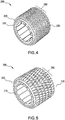
FIG. 4 illustrates additional features of a stator according to another embodiment; -
FIG. 5 illustrates additional features of a stator according to another embodiment; -
FIG. 6 illustrates features of a stator with a support frame according to an embodiment; -
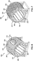
FIG. 7 illustrates features of a stator with a support frame according to another embodiment; -
FIG. 8 illustrates additional features of a stator according to another embodiment; -
FIG. 9 illustrates additional features of a stator according to another embodiment; -
FIG. 10 illustrates features of a motor that includes a stator according to an embodiment; and -
FIG. 11 illustrates a process of manufacturing a stator according to an embodiment. - A detailed description of one or more embodiments of the disclosed apparatus and method are presented herein by way of exemplification and not limitation with reference to the Figures.
- Turning to
FIG. 1 , disclosed is astator 200 comprising a firstcylindrical member 210 that may have a first plurality of axially opposing ends including a firstfront end 220 and afirst back end 230 mutually spaced along a firststator center axis 240. Thefirst member 210 may have a first outer diameter (OD)side 250 and a first inner diameter (ID)side 260. In addition, thefirst member 210 can be formed of material such as laminated electrical steel. - In one embodiment, a
base layer 270, a portion of which is illustrated schematically inFIG. 1 , may be disposed directly against thefirst OD side 250 of thefirst member 210. Thisbase layer 270 can be formed of material that is different than the material forming thefirst member 210. In one embodiment, thebase layer 270 is formed of material, such as, aluminum or an aluminum alloy, copper, diamond, carbon composites etc. - A plurality of cooling features 280, including a
first fin 290, may be disposed directly against and extend radially outwardly from thefirst member 210. In one embodiment that is configured with thebase layer 270, thecooling features 280 may be disposed directly against and extend radially outwardly from thebase layer 270. It is to be appreciated that only a few of the plurality offins 280 are illustrated inFIG. 1 . In one embodiment, the plurality offins 280 spans between the first plurality of axiallyopposing ends first member 210. The plurality offins 280 may be formed of a different material than thefirst member 210 and the same material as thebase layer 270. - According to an embodiment, the base layer and/or plurality of
cooling features 280 may be additively manufactured onto thestator 200 by an appropriate technique, such as, wire arc additive manufacturing and/or direct energy deposition and/or powder deposition and/or cold spray, and/or electron beam etc. With this configuration thermal contact resistance will be improved (lowered) compared with other electrical machine interfaces manufactured by shrink-fit, press-fit, assembly etc. - Turning to
FIGS. 2-3 , the plurality ofcooling features 280 may be one or more of (i) a plurality of discrete members (FIG. 2 ) and (ii) a plurality of continuous members (FIG. 3 ). As illustrated inFIG. 2 , the plurality ofcooling features 280 may be discrete members having an arcuate cross section. The cross section can be elliptical in one embodiment. Alternatively the cooling features may have a circular shape, a teardrop shape, an air-foil shape, and the like, which may be beneficial for enabling flow of a cooling medium thereover. As illustrated inFIG. 4 , the plurality ofcooling features 280 may be discrete members having an arcuate cross section that is circular. As illustrated inFIG. 5 , the plurality ofcooling features 280 may be discrete members having a cross section that is rectangular. In the embodiment illustrated inFIG. 3 , the plurality ofcooling features 280 may be continuous members forming a waveform, and more specifically a triangular waveform. - Turning to
FIGS. 6 and 7 , asupport frame 300 is provided. Thesupport frame 300 may support the opposingaxial ends first member 210. As illustrated inFIG. 6 , thesupport frame 300 may comprise a secondcylindrical member 310 surrounding thefirst member 210 between the first plurality of axiallyopposing ends first member 210. Thesecond member 310 may include a plurality ofperforations 320, including afirst perforation 330. The plurality of cooling features 280 may be fixedly attached to thestator 200, again illustrated schematically, through the respective plurality ofperforations 320. In the embodiment with thebase layer 270, the plurality of cooling features 280 may be fixedly attached to thebase layer 270. In an embodiment where the cooling features 280 are additively manufactured, the cooling features 280 are printed directly on thebase layer 270 through the openings of the perforated frame. - As illustrated in
FIG. 7 , thesupport frame 300 may comprise a plurality of axially opposing support rings, including a frontend support ring 340 and a backend support ring 350. The frontend support ring 340 supports thefront end 220 of thefirst member 210. The backend support ring 350 supporting theback end 230 of thefirst member 210. The plurality of cooling features 280 is disposed axially between the plurality of support rings. In one embodiment one or more axially extending support bars 355 may be further provided for relatively improved torque transfer. The support bars 335 may be included with embodiments having end frame rings 340, 350 and/or acylindrical frame 310 with perforated openings 320 (FIG. 6 ) whereuponfins 280 may be printed directly on the statorouter diameter side 250 for providing yet further improved torque transfer. - Turning to
FIGS. 8 and 9 , additional embodiments of thestator 200 are illustrated in which the fin features are varied between opposingaxial ends FIG. 8 , one or more annular rings offins 352 may have a parallelogram cross sectional shape, where the fins are at a skewed angle relative to thestator axis 240. Another one or more annular rings offins 354 may have an oval shape, where the fins have a central axis that is parallel to thestator axis 240. In addition, theannular rings stator axis 240. InFIG. 9 , one or more annular rings of fins 356 proximate opposing axial ends 220, 230 may each have a circular cross sections while one or more axially centered annular rings of fins 358 may each have an oval shape. These configurations are not intended to be limiting. These configurations may provide localized focused cooling by having non-uniform cooling features / patterns of fins to provide variable cooling features. - As illustrated in
FIG. 10 , amotor 360 having thestator 200 with the above disclosedfins 280 may havecopper windings 370 affixed to thefirst ID side 260 of thefirst member 210. Arotor 380 may be disposed within thestator 200. Thefins 280 are built up over thebase layer 270. - The above disclosed embodiments identify multiple additive manufacturing methods, such as cold spray, to deposit
fins 280 onto asteel stator 200 of amotor 360 for improved cooling. That is, the disclosed embodiments providecooling fins 280 architecture utilize additive manufacturing techniques, such as aluminum alloy cold spray, WAAM, direct laser deposition, to directly printfins 280 on astator OD side 250. Coolingfins 280 on external additively manufactured layers of thestator 200 may be configured in a pin (circular) fin and/or a plate (rectangular) fin geometry. By eliminating and/or minimizing a circular frame over thestator OD side 250, the thermal contact resistance may be reduced between heat sources, for example the stator, the coil (windings), and thefins 280. This may result in a relatively enhanced cooling performance. That is, thermal contact resistance measurements, with the use of WAAM and cold spray layering, may be relatively reduced. - Turning to
FIG. 11 , the process S200 of fabricating thefins 280 on thestator 200 may include step S210 of cold spraying to deposit thealuminum base layer 270. A bonding mechanism for cold spray may be a solid state that avoids issues of melt fusion of aluminum onto steel, as the melt fusion may create brittle intermetallics and residual stresses that weaken the interface. In addition, at step S220 a melt-based process (wire arc additive manufacturing (WAAM) or directed energy deposition) may be utilized to create walls orfins 280. For this second part of the process, a melt pool may be kept shallow to interact with the only the cold spray layer thus avoiding any interaction with the steel. - In one embodiment the
fins 280 may be made using an additive technique or via a conventional sheet metal bending, followed by brazing, for friction welding. In such an embodiment, analuminum base layer 310 is deposited first by an additive method such as cold spray and then a preformed sleeve offins 280 is bonded onto thebase layer 310. - One or more benefits of the above disclosed embodiments may be an improved thermal management of
motors 360. This benefit may be enabled by additive deposition of aluminum cooling features using two methods in tandem. That is, there may be an improved heat transfer from a reduction in thermal resistance and an elimination of thermal contacts between thestator 200 andframe 300. In addition, an improved convective heat transfer may be possible from a relatively efficient fin structure. In addition, an alternate torque transfer mechanism may be provided by the above process as well as a weight savings, which may be obtained by removing material from theframe 300. The embodiments may also provide an ability to operate amotor 360 at a relatively higher current density, which may provide an increased power density. - The term "about" is intended to include the degree of error associated with measurement of the particular quantity based upon the equipment available at the time of filing the application.
- The terminology used herein is for the purpose of describing particular embodiments only and is not intended to be limiting of the present disclosure. As used herein, the singular forms "a", "an" and "the" are intended to include the plural forms as well, unless the context clearly indicates otherwise. It will be further understood that the terms "comprises" and/or "comprising," when used in this specification, specify the presence of stated features, integers, steps, operations, elements, and/or components, but do not preclude the presence or addition of one or more other features, integers, steps, operations, element components, and/or groups thereof.
- While the present disclosure has been described with reference to an exemplary embodiment or embodiments, it will be understood by those skilled in the art that various changes may be made and equivalents may be substituted for elements thereof without departing from the scope of the invention as defined by the claims. In addition, many modifications may be made to adapt a particular situation or material to the teachings of the present disclosure without departing from the scope of the invention. Therefore, it is intended that the present disclosure not be limited to the particular embodiment disclosed as the best mode contemplated for carrying out this present disclosure, but that the present disclosure will include all embodiments falling within the scope of the claims.
Claims (15)
- A stator comprising:a first member (210) having a first plurality of axially opposing ends including a first front end (220) and a first back end (230) mutually spaced along a first stator center axis (240), a first outer diameter, OD, side (250) and a first inner diameter (ID) side, wherein first member comprises laminated steel;a plurality of cooling features (280) disposed directly against the first member, wherein the plurality of cooling features spans between the first plurality of axially opposing ends of the first member, andwherein:
the stator comprises a base layer (270) disposed directly against the first member, between the first member and the cooling features, thereby reducing an interface contact resistance between the first member and the plurality of cooling features. - The stator of claim 1, wherein the plurality of cooling features is one or more of (i) a plurality of discrete fins and (ii) a plurality of continuous fins.
- The stator of claim 1 or 2, wherein the plurality of cooling features has a cross section that is one or more of rectangular, oval, arcuate, and circular, or wherein the plurality of cooling features have a cross section that is one or more of a discrete elliptical cross section and a discrete circular cross section.
- The stator of any preceding claim, wherein the plurality of cooling features form an axially continuous waveform.
- The stator of claim 4, wherein the plurality of cooling features are disposed directly against and extend radially outwardly from the base layer.
- The stator of any preceding claim, including a support frame (300) supporting the opposing axial ends of the first member.
- The stator of claim 6, wherein the support frame comprises a second member (310) surrounding the first member between the first plurality of axially opposing ends, the second member including a plurality of perforations (320), wherein the plurality of cooling features is additively manufactured onto the stator through the respective plurality of perforations, and wherein a shape of the perforations defines a cross sectional shape of the respective cooling features for at least a portion of a span of the respective cooling features.
- The stator of claim 7, wherein the support frame comprises a plurality of support rings (340,350), including a front end support ring (340) supporting the first front of the first member and a back end support ring (350) supporting the first back end of the first member, the plurality of cooling features being disposed axially between the plurality of support rings.
- A motor including the stator of any preceding claim, comprising copper windings disposed on the first ID side of the first member, and a rotor disposed within the stator.
- A method of configuring a stator, comprising:providing a first member (210), the member comprising a first plurality of axially opposing ends including a first front end (220) and a first back end (230), a first outer diameter, OD, side (250) and a first inner diameter, ID, side (260), wherein first member comprises steel;hot forming a plurality of cooling features (280) directly against and extending radially outwardly from the first member, wherein the plurality of cooling features spans between the first plurality of axially opposing ends of the first member; andlayering, by cold spraying deposition, a base layer (270) directly against the first OD side of the first member, thereby reducing an interface contact resistance between the first member and the plurality of cooling features.
- The method of claim 10 wherein the plurality of cooling features is one or more of (i) a plurality of discrete fins and (ii) a plurality of axially continuous fins.
- The method of claim 11, wherein the plurality of cooling features has a cross section that is one or more of a rectangular, oval, arcuate, and circular, or wherein the plurality of cooling features has a cross section that is one or more of a discrete elliptical cross section and a discrete circular cross section.
- The method of any of claims 10 to 12, comprising:
wherein the plurality of cooling features are one or more of hot formed directly against and extend radially outwardly from and the base layer and bonding a preformed sleeve of fins onto the base layer. - The method of any of claims 10 t0 13, further comprising:
forming a support frame (300) around the first member, and preferably wherein the support frame comprises a second member (310) surrounding the first member between the first plurality of axially opposing ends, the second member including a plurality of perforations (320), wherein the plurality of cooling features is additively manufactured onto the stator through the respective plurality of perforations, and preferably wherein the support frame comprises a plurality of support rings (340,350), including a front end support ring supporting the first front end of the first member and a back end support ring supporting the first back end of the first member, the plurality of cooling features being disposed axially between the plurality of support rings. - A method of configuring a motor, the method including: configuring a stator according to any of claims 10 to 14, disposing copper windings on the first ID side of the first member of the stator, and disposing a rotor within the stator.
Applications Claiming Priority (1)
| Application Number | Priority Date | Filing Date | Title |
|---|---|---|---|
| US16/125,001 US10873239B2 (en) | 2018-09-07 | 2018-09-07 | Electric machine cooling features |
Publications (2)
| Publication Number | Publication Date |
|---|---|
| EP3621183A1 true EP3621183A1 (en) | 2020-03-11 |
| EP3621183B1 EP3621183B1 (en) | 2021-08-18 |
Family
ID=67777238
Family Applications (1)
| Application Number | Title | Priority Date | Filing Date |
|---|---|---|---|
| EP19194149.1A Active EP3621183B1 (en) | 2018-09-07 | 2019-08-28 | Electric machine cooling features |
Country Status (2)
| Country | Link |
|---|---|
| US (1) | US10873239B2 (en) |
| EP (1) | EP3621183B1 (en) |
Cited By (3)
| Publication number | Priority date | Publication date | Assignee | Title |
|---|---|---|---|---|
| DE102019133548A1 (en) * | 2019-12-09 | 2021-06-10 | Valeo Siemens Eautomotive Germany Gmbh | Stator housing for an electric machine, electric machine for a vehicle, and a vehicle |
| WO2023073219A1 (en) * | 2021-10-28 | 2023-05-04 | Renault S.A.S. | Method for manufacturing a stator body |
| US20250015684A1 (en) * | 2023-07-05 | 2025-01-09 | Schaeffler Technologies AG & Co. KG | Stator carrier for a drive unit |
Families Citing this family (8)
| Publication number | Priority date | Publication date | Assignee | Title |
|---|---|---|---|---|
| CN110635587B (en) * | 2018-09-14 | 2020-12-29 | 北京金风科创风电设备有限公司 | Stator assembly and motor having the same |
| US11444507B2 (en) * | 2019-10-04 | 2022-09-13 | Hamilton Sundstrand Corporation | Actuation motor with cooling fins |
| AU2021407395A1 (en) * | 2020-12-24 | 2023-06-29 | Commonwealth Scientific And Industrial Research Organisation | Process for producing a metallic structure by additive manufacturing |
| CN113675998B (en) * | 2021-10-25 | 2022-02-08 | 南通市海王电气有限公司 | Self-auxiliary shaking type double-air-cooled motor |
| US12273008B2 (en) * | 2022-07-08 | 2025-04-08 | Honeywell International Inc. | Cooling a high-power electric machine |
| FR3157028A1 (en) * | 2023-12-19 | 2025-06-20 | Safran Electrical & Power | Housing comprising a heat sink equipped with fins oriented with a non-zero angle of incidence |
| WO2025133496A1 (en) * | 2023-12-19 | 2025-06-26 | Safran Electrical & Power | Casing having a heat sink provided with fins oriented at a non-zero angle of incidence |
| JP2025139114A (en) * | 2024-03-12 | 2025-09-26 | トヨタ自動車株式会社 | cooling structure |
Citations (7)
| Publication number | Priority date | Publication date | Assignee | Title |
|---|---|---|---|---|
| JPS5734747A (en) * | 1980-08-08 | 1982-02-25 | Toshiba Corp | Rotary electric machine |
| JPS58222753A (en) * | 1982-06-17 | 1983-12-24 | Toshiba Corp | Rotary electric machine |
| JPS59220054A (en) * | 1983-05-27 | 1984-12-11 | Mitsubishi Electric Corp | Manufacture of frame for motor |
| JP2014050133A (en) * | 2012-08-29 | 2014-03-17 | Ihi Corp | Rotor, electric motor, and supercharger |
| EP3076526A1 (en) * | 2015-04-02 | 2016-10-05 | Hamilton Sundstrand Corporation | Stator heat transfer feature |
| US20180205285A1 (en) * | 2017-01-13 | 2018-07-19 | Ge Aviation Systems Llc | Method for manufacturing an integrated stator and housing for an electrical machine |
| FR3063403A1 (en) * | 2017-02-28 | 2018-08-31 | Safran Aircraft Engines | ELECTRIC MOTOR OF AN AIRCRAFT COMPRISING A MONOBLOC FINAL COOLING SYSTEM WITH THE STATOR |
Family Cites Families (13)
| Publication number | Priority date | Publication date | Assignee | Title |
|---|---|---|---|---|
| JPS61180553A (en) | 1985-02-06 | 1986-08-13 | Mitsubishi Electric Corp | Manufacture of frame for rotary electric machine |
| US8378546B2 (en) * | 2003-12-12 | 2013-02-19 | Sten R. Gerfast | Generator with output options and low loss windings |
| US10574110B2 (en) | 2010-04-28 | 2020-02-25 | Launchpoint Technologies, Inc. | Lightweight and efficient electrical machine and method of manufacture |
| GB2504302A (en) * | 2012-07-24 | 2014-01-29 | Brayton Energy Canada Inc | Heat exchanger fins made by cold spraying |
| EP2806535A1 (en) * | 2013-05-24 | 2014-11-26 | Siemens Aktiengesellschaft | Air-cooled electric machine with cooling fins made from stator sheet metal |
| WO2016096042A1 (en) * | 2014-12-19 | 2016-06-23 | Arcelik Anonim Sirketi | Individual cooling fin and an electric motor having the same |
| US11387725B2 (en) | 2015-05-27 | 2022-07-12 | Hamilton Sundstrand Corporation | Integrated heat dissipative structure for electric machine |
| CN108140746B (en) | 2015-06-30 | 2022-03-08 | 法拉第未来公司 | Vehicle energy storage system |
| US9755463B2 (en) | 2015-08-11 | 2017-09-05 | Genesis Robotics Llp | Electric machine |
| US10476358B2 (en) | 2017-01-13 | 2019-11-12 | General Electric Company | Methods for manufacturing an electric machine |
| US10424989B2 (en) | 2017-01-13 | 2019-09-24 | General Electric Company | Methods for manufacturing a housing for an electrical machine |
| US10523096B2 (en) | 2017-01-13 | 2019-12-31 | Ge Aviation Systems Llc | Method for manufacturing a stator assembly of an electrical machine |
| US10792750B2 (en) | 2017-01-13 | 2020-10-06 | Ge Aviation Systems Llc | Methods for manufacturing a rotor assembly for an electrical machine |
-
2018
- 2018-09-07 US US16/125,001 patent/US10873239B2/en active Active
-
2019
- 2019-08-28 EP EP19194149.1A patent/EP3621183B1/en active Active
Patent Citations (7)
| Publication number | Priority date | Publication date | Assignee | Title |
|---|---|---|---|---|
| JPS5734747A (en) * | 1980-08-08 | 1982-02-25 | Toshiba Corp | Rotary electric machine |
| JPS58222753A (en) * | 1982-06-17 | 1983-12-24 | Toshiba Corp | Rotary electric machine |
| JPS59220054A (en) * | 1983-05-27 | 1984-12-11 | Mitsubishi Electric Corp | Manufacture of frame for motor |
| JP2014050133A (en) * | 2012-08-29 | 2014-03-17 | Ihi Corp | Rotor, electric motor, and supercharger |
| EP3076526A1 (en) * | 2015-04-02 | 2016-10-05 | Hamilton Sundstrand Corporation | Stator heat transfer feature |
| US20180205285A1 (en) * | 2017-01-13 | 2018-07-19 | Ge Aviation Systems Llc | Method for manufacturing an integrated stator and housing for an electrical machine |
| FR3063403A1 (en) * | 2017-02-28 | 2018-08-31 | Safran Aircraft Engines | ELECTRIC MOTOR OF AN AIRCRAFT COMPRISING A MONOBLOC FINAL COOLING SYSTEM WITH THE STATOR |
Cited By (6)
| Publication number | Priority date | Publication date | Assignee | Title |
|---|---|---|---|---|
| DE102019133548A1 (en) * | 2019-12-09 | 2021-06-10 | Valeo Siemens Eautomotive Germany Gmbh | Stator housing for an electric machine, electric machine for a vehicle, and a vehicle |
| US12334777B2 (en) | 2019-12-09 | 2025-06-17 | Valeo Siemens Eautomotive Germany Gmbh | Stator housing for an electrical machine, electrical machine for a vehicle, and vehicle |
| WO2023073219A1 (en) * | 2021-10-28 | 2023-05-04 | Renault S.A.S. | Method for manufacturing a stator body |
| FR3128833A1 (en) * | 2021-10-28 | 2023-05-05 | Renault S.A.S. | Process for manufacturing a stator body |
| US20250015684A1 (en) * | 2023-07-05 | 2025-01-09 | Schaeffler Technologies AG & Co. KG | Stator carrier for a drive unit |
| US12463509B2 (en) * | 2023-07-05 | 2025-11-04 | Schaeffler Technologies AG & Co. KG | Stator carrier for a drive unit |
Also Published As
| Publication number | Publication date |
|---|---|
| EP3621183B1 (en) | 2021-08-18 |
| US10873239B2 (en) | 2020-12-22 |
| US20200083783A1 (en) | 2020-03-12 |
Similar Documents
| Publication | Publication Date | Title |
|---|---|---|
| EP3621183B1 (en) | Electric machine cooling features | |
| JP5155420B2 (en) | Cage rotor of induction motor for brazing end ring and bar and manufacturing method thereof | |
| CN102801259B (en) | Induction rotor assembly and method of manufacturing same | |
| US8643241B2 (en) | End ring assembly and method of forming same | |
| US8365392B2 (en) | Method of fabricating a rotor assembly for an electric motor | |
| US6856063B1 (en) | Electromotive devices using notched ribbon windings | |
| JP3704044B2 (en) | Armature for electric devices | |
| US20130033144A1 (en) | Stir-welded induction rotor | |
| US8878414B2 (en) | Stator weld joints and methods of forming same | |
| CN107078581B (en) | Stator of rotating electric machine | |
| US20240322619A1 (en) | Stator for a radial flux double-rotor machine, radial flux double-rotor machine and method for producing a stator for a radial flux double-rotor machine | |
| JP2022511222A5 (en) | ||
| CN103795195B (en) | Induction rotor and method for fabricating the same | |
| JP2002119003A (en) | Stator of rotating electric machine and method of manufacturing the same | |
| US6877210B2 (en) | Electrofriction method of manufacturing squirrel cage rotors | |
| CN108880043B (en) | Electric machine and method for making electric machine | |
| US11177708B2 (en) | Method for manufacturing an integrated stator and housing for an electrical machine | |
| CN111869061B (en) | Method for manufacturing squirrel cage rotor | |
| EP3494627B1 (en) | Electric machines | |
| US20170194838A1 (en) | Fixture and method of securing parts using the same | |
| GB2574409A (en) | Stator for a multi-phase electrical machine | |
| JP3921185B2 (en) | Electric machine | |
| US11527944B2 (en) | Additive manufacturing for segmented electric machines | |
| JP2015061459A (en) | Induction motor and method of manufacturing induction motor | |
| JPH08331813A (en) | Method for manufacturing rotor of rotating electric machine |
Legal Events
| Date | Code | Title | Description |
|---|---|---|---|
| PUAI | Public reference made under article 153(3) epc to a published international application that has entered the european phase |
Free format text: ORIGINAL CODE: 0009012 |
|
| STAA | Information on the status of an ep patent application or granted ep patent |
Free format text: STATUS: THE APPLICATION HAS BEEN PUBLISHED |
|
| AK | Designated contracting states |
Kind code of ref document: A1 Designated state(s): AL AT BE BG CH CY CZ DE DK EE ES FI FR GB GR HR HU IE IS IT LI LT LU LV MC MK MT NL NO PL PT RO RS SE SI SK SM TR |
|
| AX | Request for extension of the european patent |
Extension state: BA ME |
|
| STAA | Information on the status of an ep patent application or granted ep patent |
Free format text: STATUS: REQUEST FOR EXAMINATION WAS MADE |
|
| 17P | Request for examination filed |
Effective date: 20200911 |
|
| RBV | Designated contracting states (corrected) |
Designated state(s): AL AT BE BG CH CY CZ DE DK EE ES FI FR GB GR HR HU IE IS IT LI LT LU LV MC MK MT NL NO PL PT RO RS SE SI SK SM TR |
|
| GRAP | Despatch of communication of intention to grant a patent |
Free format text: ORIGINAL CODE: EPIDOSNIGR1 |
|
| STAA | Information on the status of an ep patent application or granted ep patent |
Free format text: STATUS: GRANT OF PATENT IS INTENDED |
|
| INTG | Intention to grant announced |
Effective date: 20210316 |
|
| GRAS | Grant fee paid |
Free format text: ORIGINAL CODE: EPIDOSNIGR3 |
|
| GRAA | (expected) grant |
Free format text: ORIGINAL CODE: 0009210 |
|
| STAA | Information on the status of an ep patent application or granted ep patent |
Free format text: STATUS: THE PATENT HAS BEEN GRANTED |
|
| AK | Designated contracting states |
Kind code of ref document: B1 Designated state(s): AL AT BE BG CH CY CZ DE DK EE ES FI FR GB GR HR HU IE IS IT LI LT LU LV MC MK MT NL NO PL PT RO RS SE SI SK SM TR |
|
| REG | Reference to a national code |
Ref country code: GB Ref legal event code: FG4D |
|
| REG | Reference to a national code |
Ref country code: CH Ref legal event code: EP |
|
| REG | Reference to a national code |
Ref country code: DE Ref legal event code: R096 Ref document number: 602019006928 Country of ref document: DE |
|
| REG | Reference to a national code |
Ref country code: IE Ref legal event code: FG4D Ref country code: AT Ref legal event code: REF Ref document number: 1422516 Country of ref document: AT Kind code of ref document: T Effective date: 20210915 |
|
| REG | Reference to a national code |
Ref country code: LT Ref legal event code: MG9D |
|
| REG | Reference to a national code |
Ref country code: NL Ref legal event code: MP Effective date: 20210818 |
|
| REG | Reference to a national code |
Ref country code: AT Ref legal event code: MK05 Ref document number: 1422516 Country of ref document: AT Kind code of ref document: T Effective date: 20210818 |
|
| PG25 | Lapsed in a contracting state [announced via postgrant information from national office to epo] |
Ref country code: ES Free format text: LAPSE BECAUSE OF FAILURE TO SUBMIT A TRANSLATION OF THE DESCRIPTION OR TO PAY THE FEE WITHIN THE PRESCRIBED TIME-LIMIT Effective date: 20210818 Ref country code: FI Free format text: LAPSE BECAUSE OF FAILURE TO SUBMIT A TRANSLATION OF THE DESCRIPTION OR TO PAY THE FEE WITHIN THE PRESCRIBED TIME-LIMIT Effective date: 20210818 Ref country code: RS Free format text: LAPSE BECAUSE OF FAILURE TO SUBMIT A TRANSLATION OF THE DESCRIPTION OR TO PAY THE FEE WITHIN THE PRESCRIBED TIME-LIMIT Effective date: 20210818 Ref country code: SE Free format text: LAPSE BECAUSE OF FAILURE TO SUBMIT A TRANSLATION OF THE DESCRIPTION OR TO PAY THE FEE WITHIN THE PRESCRIBED TIME-LIMIT Effective date: 20210818 Ref country code: HR Free format text: LAPSE BECAUSE OF FAILURE TO SUBMIT A TRANSLATION OF THE DESCRIPTION OR TO PAY THE FEE WITHIN THE PRESCRIBED TIME-LIMIT Effective date: 20210818 Ref country code: PT Free format text: LAPSE BECAUSE OF FAILURE TO SUBMIT A TRANSLATION OF THE DESCRIPTION OR TO PAY THE FEE WITHIN THE PRESCRIBED TIME-LIMIT Effective date: 20211220 Ref country code: NO Free format text: LAPSE BECAUSE OF FAILURE TO SUBMIT A TRANSLATION OF THE DESCRIPTION OR TO PAY THE FEE WITHIN THE PRESCRIBED TIME-LIMIT Effective date: 20211118 Ref country code: LT Free format text: LAPSE BECAUSE OF FAILURE TO SUBMIT A TRANSLATION OF THE DESCRIPTION OR TO PAY THE FEE WITHIN THE PRESCRIBED TIME-LIMIT Effective date: 20210818 Ref country code: BG Free format text: LAPSE BECAUSE OF FAILURE TO SUBMIT A TRANSLATION OF THE DESCRIPTION OR TO PAY THE FEE WITHIN THE PRESCRIBED TIME-LIMIT Effective date: 20211118 Ref country code: AT Free format text: LAPSE BECAUSE OF FAILURE TO SUBMIT A TRANSLATION OF THE DESCRIPTION OR TO PAY THE FEE WITHIN THE PRESCRIBED TIME-LIMIT Effective date: 20210818 |
|
| PG25 | Lapsed in a contracting state [announced via postgrant information from national office to epo] |
Ref country code: PL Free format text: LAPSE BECAUSE OF FAILURE TO SUBMIT A TRANSLATION OF THE DESCRIPTION OR TO PAY THE FEE WITHIN THE PRESCRIBED TIME-LIMIT Effective date: 20210818 Ref country code: LV Free format text: LAPSE BECAUSE OF FAILURE TO SUBMIT A TRANSLATION OF THE DESCRIPTION OR TO PAY THE FEE WITHIN THE PRESCRIBED TIME-LIMIT Effective date: 20210818 Ref country code: GR Free format text: LAPSE BECAUSE OF FAILURE TO SUBMIT A TRANSLATION OF THE DESCRIPTION OR TO PAY THE FEE WITHIN THE PRESCRIBED TIME-LIMIT Effective date: 20211119 |
|
| PG25 | Lapsed in a contracting state [announced via postgrant information from national office to epo] |
Ref country code: NL Free format text: LAPSE BECAUSE OF FAILURE TO SUBMIT A TRANSLATION OF THE DESCRIPTION OR TO PAY THE FEE WITHIN THE PRESCRIBED TIME-LIMIT Effective date: 20210818 |
|
| REG | Reference to a national code |
Ref country code: BE Ref legal event code: MM Effective date: 20210831 |
|
| PG25 | Lapsed in a contracting state [announced via postgrant information from national office to epo] |
Ref country code: DK Free format text: LAPSE BECAUSE OF FAILURE TO SUBMIT A TRANSLATION OF THE DESCRIPTION OR TO PAY THE FEE WITHIN THE PRESCRIBED TIME-LIMIT Effective date: 20210818 |
|
| REG | Reference to a national code |
Ref country code: DE Ref legal event code: R097 Ref document number: 602019006928 Country of ref document: DE |
|
| PG25 | Lapsed in a contracting state [announced via postgrant information from national office to epo] |
Ref country code: SM Free format text: LAPSE BECAUSE OF FAILURE TO SUBMIT A TRANSLATION OF THE DESCRIPTION OR TO PAY THE FEE WITHIN THE PRESCRIBED TIME-LIMIT Effective date: 20210818 Ref country code: SK Free format text: LAPSE BECAUSE OF FAILURE TO SUBMIT A TRANSLATION OF THE DESCRIPTION OR TO PAY THE FEE WITHIN THE PRESCRIBED TIME-LIMIT Effective date: 20210818 Ref country code: RO Free format text: LAPSE BECAUSE OF FAILURE TO SUBMIT A TRANSLATION OF THE DESCRIPTION OR TO PAY THE FEE WITHIN THE PRESCRIBED TIME-LIMIT Effective date: 20210818 Ref country code: MC Free format text: LAPSE BECAUSE OF FAILURE TO SUBMIT A TRANSLATION OF THE DESCRIPTION OR TO PAY THE FEE WITHIN THE PRESCRIBED TIME-LIMIT Effective date: 20210818 Ref country code: LU Free format text: LAPSE BECAUSE OF NON-PAYMENT OF DUE FEES Effective date: 20210828 Ref country code: EE Free format text: LAPSE BECAUSE OF FAILURE TO SUBMIT A TRANSLATION OF THE DESCRIPTION OR TO PAY THE FEE WITHIN THE PRESCRIBED TIME-LIMIT Effective date: 20210818 Ref country code: CZ Free format text: LAPSE BECAUSE OF FAILURE TO SUBMIT A TRANSLATION OF THE DESCRIPTION OR TO PAY THE FEE WITHIN THE PRESCRIBED TIME-LIMIT Effective date: 20210818 Ref country code: AL Free format text: LAPSE BECAUSE OF FAILURE TO SUBMIT A TRANSLATION OF THE DESCRIPTION OR TO PAY THE FEE WITHIN THE PRESCRIBED TIME-LIMIT Effective date: 20210818 |
|
| PLBE | No opposition filed within time limit |
Free format text: ORIGINAL CODE: 0009261 |
|
| STAA | Information on the status of an ep patent application or granted ep patent |
Free format text: STATUS: NO OPPOSITION FILED WITHIN TIME LIMIT |
|
| 26N | No opposition filed |
Effective date: 20220519 |
|
| PG25 | Lapsed in a contracting state [announced via postgrant information from national office to epo] |
Ref country code: IT Free format text: LAPSE BECAUSE OF FAILURE TO SUBMIT A TRANSLATION OF THE DESCRIPTION OR TO PAY THE FEE WITHIN THE PRESCRIBED TIME-LIMIT Effective date: 20210818 Ref country code: IE Free format text: LAPSE BECAUSE OF NON-PAYMENT OF DUE FEES Effective date: 20210828 Ref country code: BE Free format text: LAPSE BECAUSE OF NON-PAYMENT OF DUE FEES Effective date: 20210831 |
|
| PG25 | Lapsed in a contracting state [announced via postgrant information from national office to epo] |
Ref country code: SI Free format text: LAPSE BECAUSE OF FAILURE TO SUBMIT A TRANSLATION OF THE DESCRIPTION OR TO PAY THE FEE WITHIN THE PRESCRIBED TIME-LIMIT Effective date: 20210818 |
|
| REG | Reference to a national code |
Ref country code: CH Ref legal event code: PL |
|
| PG25 | Lapsed in a contracting state [announced via postgrant information from national office to epo] |
Ref country code: LI Free format text: LAPSE BECAUSE OF NON-PAYMENT OF DUE FEES Effective date: 20220831 Ref country code: CH Free format text: LAPSE BECAUSE OF NON-PAYMENT OF DUE FEES Effective date: 20220831 |
|
| P01 | Opt-out of the competence of the unified patent court (upc) registered |
Effective date: 20230522 |
|
| PG25 | Lapsed in a contracting state [announced via postgrant information from national office to epo] |
Ref country code: CY Free format text: LAPSE BECAUSE OF FAILURE TO SUBMIT A TRANSLATION OF THE DESCRIPTION OR TO PAY THE FEE WITHIN THE PRESCRIBED TIME-LIMIT Effective date: 20210818 |
|
| PG25 | Lapsed in a contracting state [announced via postgrant information from national office to epo] |
Ref country code: HU Free format text: LAPSE BECAUSE OF FAILURE TO SUBMIT A TRANSLATION OF THE DESCRIPTION OR TO PAY THE FEE WITHIN THE PRESCRIBED TIME-LIMIT; INVALID AB INITIO Effective date: 20190828 |
|
| PG25 | Lapsed in a contracting state [announced via postgrant information from national office to epo] |
Ref country code: MK Free format text: LAPSE BECAUSE OF FAILURE TO SUBMIT A TRANSLATION OF THE DESCRIPTION OR TO PAY THE FEE WITHIN THE PRESCRIBED TIME-LIMIT Effective date: 20210818 |
|
| PG25 | Lapsed in a contracting state [announced via postgrant information from national office to epo] |
Ref country code: MT Free format text: LAPSE BECAUSE OF FAILURE TO SUBMIT A TRANSLATION OF THE DESCRIPTION OR TO PAY THE FEE WITHIN THE PRESCRIBED TIME-LIMIT Effective date: 20210818 |
|
| PGFP | Annual fee paid to national office [announced via postgrant information from national office to epo] |
Ref country code: DE Payment date: 20250724 Year of fee payment: 7 |
|
| PGFP | Annual fee paid to national office [announced via postgrant information from national office to epo] |
Ref country code: GB Payment date: 20250724 Year of fee payment: 7 |
|
| PGFP | Annual fee paid to national office [announced via postgrant information from national office to epo] |
Ref country code: FR Payment date: 20250723 Year of fee payment: 7 |
|
| PG25 | Lapsed in a contracting state [announced via postgrant information from national office to epo] |
Ref country code: TR Free format text: LAPSE BECAUSE OF FAILURE TO SUBMIT A TRANSLATION OF THE DESCRIPTION OR TO PAY THE FEE WITHIN THE PRESCRIBED TIME-LIMIT Effective date: 20210818 |