EP3621177A1 - Systems and methods for a wireless charging mount - Google Patents
Systems and methods for a wireless charging mount Download PDFInfo
- Publication number
- EP3621177A1 EP3621177A1 EP19195526.9A EP19195526A EP3621177A1 EP 3621177 A1 EP3621177 A1 EP 3621177A1 EP 19195526 A EP19195526 A EP 19195526A EP 3621177 A1 EP3621177 A1 EP 3621177A1
- Authority
- EP
- European Patent Office
- Prior art keywords
- charging
- coil
- mount
- module
- portable device
- Prior art date
- Legal status (The legal status is an assumption and is not a legal conclusion. Google has not performed a legal analysis and makes no representation as to the accuracy of the status listed.)
- Granted
Links
Images


Classifications
-
- H—ELECTRICITY
- H02—GENERATION; CONVERSION OR DISTRIBUTION OF ELECTRIC POWER
- H02J—ELECTRIC POWER NETWORKS; CIRCUIT ARRANGEMENTS OR SYSTEMS FOR SUPPLYING OR DISTRIBUTING ELECTRIC POWER; SYSTEMS FOR STORING ELECTRIC ENERGY
- H02J50/00—Circuit arrangements or systems for wireless supply or distribution of electric power
- H02J50/005—Mechanical details of housing or structure aiming to accommodate the power transfer means, e.g. mechanical integration of coils, antennas or transducers into emitting or receiving devices
-
- H—ELECTRICITY
- H02—GENERATION; CONVERSION OR DISTRIBUTION OF ELECTRIC POWER
- H02J—ELECTRIC POWER NETWORKS; CIRCUIT ARRANGEMENTS OR SYSTEMS FOR SUPPLYING OR DISTRIBUTING ELECTRIC POWER; SYSTEMS FOR STORING ELECTRIC ENERGY
- H02J50/00—Circuit arrangements or systems for wireless supply or distribution of electric power
- H02J50/10—Circuit arrangements or systems for wireless supply or distribution of electric power using inductive coupling
-
- H—ELECTRICITY
- H02—GENERATION; CONVERSION OR DISTRIBUTION OF ELECTRIC POWER
- H02J—ELECTRIC POWER NETWORKS; CIRCUIT ARRANGEMENTS OR SYSTEMS FOR SUPPLYING OR DISTRIBUTING ELECTRIC POWER; SYSTEMS FOR STORING ELECTRIC ENERGY
- H02J7/00—Circuit arrangements for charging or discharging batteries or for supplying loads from batteries
- H02J7/50—Circuit arrangements for charging or discharging batteries or for supplying loads from batteries acting upon multiple batteries simultaneously or sequentially
-
- H—ELECTRICITY
- H04—ELECTRIC COMMUNICATION TECHNIQUE
- H04B—TRANSMISSION
- H04B1/00—Details of transmission systems, not covered by a single one of groups H04B3/00 - H04B13/00; Details of transmission systems not characterised by the medium used for transmission
- H04B1/38—Transceivers, i.e. devices in which transmitter and receiver form a structural unit and in which at least one part is used for functions of transmitting and receiving
- H04B1/3827—Portable transceivers
- H04B1/3883—Arrangements for mounting batteries or battery chargers
-
- H—ELECTRICITY
- H04—ELECTRIC COMMUNICATION TECHNIQUE
- H04B—TRANSMISSION
- H04B1/00—Details of transmission systems, not covered by a single one of groups H04B3/00 - H04B13/00; Details of transmission systems not characterised by the medium used for transmission
- H04B1/38—Transceivers, i.e. devices in which transmitter and receiver form a structural unit and in which at least one part is used for functions of transmitting and receiving
- H04B1/3827—Portable transceivers
- H04B1/3888—Arrangements for carrying or protecting transceivers
Definitions
- the present disclosure generally relates to wireless charging systems for portable devices, and in particular to charging systems configured to minimize a distance between a coil in a charging module and a coil in a portable device to allow for wireless charging when engaged to the charging module.
- Wireless charging systems use an electromagnetic field to transfer energy between two objects through induction.
- a portable device may include an inductive coil
- a charging system may include a corresponding inductive coil.
- the coils of the portable device and the charging system need to be within a minimum distance to interact and allow for effective wireless charging of the portable device.
- many protective cases used to protect the charging system and the portable device, respectively can be thick and bulky in order to provide sufficient protection from impacts or other exterior forces that may be applied to either the charging system or the portable device.
- the distance between the coil of the portable device and the coil of the charging system may be too far apart to permit effective or efficient operative interaction between the two coils during wireless charging.
- the present disclosure relates to a charging system configured to couple with a portable device and/or a protective case that encases a portable device.
- the charging system includes a charging mount to couple with the portable device and/or the protective case of the portable device and a charging module which includes a coil configured to interact with a device coil in the portable device for wireless charging of the portable device.
- the charging module may be removably coupled with the charging mount.
- the construction of the charging mount and the protective case of the portable device are configured such that the coil and the device coil can efficiently interact during a wireless charging.
- the charging mount includes a coil receiver which may define a recess or an aperture.
- the coil of the charging module may be received within the coil receiver such that the reduced material thickness of the charging module between the coil and the device coil allows for efficient interaction being established between the coil and the device coil for wireless charging.
- the coil of the charging module may be received within the coil receiver adjacent an aperture defined by the charging mount for allowing the efficient interaction between the coil and the device coil for wireless charging.
- an embodiment of a charging system includes a charging mount 102 configured to be removably coupled with a protective case 1 6 for a portable device 10 . While the present disclosure discusses the charging system 100 being coupled with the protective case 16 , in some embodiments, the charging system 100 can also couple directly with the portable device 10 .
- the portable device 10 includes a device coil 12 which is disposed within a device housing 12 .
- the portable device 10 may be a phone such as a smartphone or a tablet.
- the portable device 10 may be encased in a protective case 16 .
- the protective case 16 at least partially surrounds the device housing 12 of the portable device 10 .
- the protective case 16 may prevent wear of the device housing 12 and/or decrease any force that may be applied to the portable device 10 , for example when the portable device 10 is dropped to the ground or receives other types of impacts from an external source.
- Exemplary protective cases 16 are the JUGGERNAUT CASE, the JUGGERNAUT SLEEV, the JUGGERNAUT BUMPR, and the JUGGERNAUT IMPCT; however, the types of protective cases 16 are not limited to these specific examples.
- the charging mount 102 of charging system 100 has a mount body 106 defining a front surface 107 and an opposite rear surface 111 .
- the charging mount 102 includes a first device coupler 108 and a second device coupler 110 which extend from opposite respective first and second sides 18 , 20 of the mount body 106 .
- the first device coupler 108 is configured to abut a first side 18 of the protective case 16 and the second coupler 110 is configured to abut the second side 20 of the protective case 16 such that the protective case 16 is securely engaged to the charging mount 102 .
- the first device coupler 108 and the second device coupler 110 collectively engage with the protective case 16 by a snap fit connection.
- the first device coupler 108 and the second device coupler 110 initially engages and deflects away from the first and second sides 18 , 20 of the protective case 16 and then the first and second device couplers 108 and 110 revert to their original shape such that the protective case 16 becomes fully engaged with the charging mount 106 .
- the charging mount 106 is physically coupled with the protective case 16 and/or the portable device 10 even if the protective case 16 and/or the portable device 10 is moved or experiences an external force.
- the mount body 106 may be made of a plastic.
- the mount body 106 may be made of acrylonitrile butadiene styrene and/or polycarbonate.
- the charging system 100 may also include a coil 130 of the charging module 104 that is configured to interact with the device coil 14 of the portable device 10 for allowing wireless charging of the portable device 10 .
- the operative interaction between the coil 130 and the device coil 14 is electromagnetic induction.
- the coil 130 of the charging module 104 functions as a transmitting coil.
- the coil 130 generates an oscillating magnetic field such that the magnetic field induces an alternating current in a receiving coil, for example the device coil 14 .
- the coil 130 and the device coil 14 collectively provide inductive charging of the portable device 10 .
- the coil 130 and the device coil 14 may provide a voltage up to 5 volts and a current up to 2 amperes during charging of the portable device 10 .
- the inductive charging of the portable device 10 operates under the QI standard.
- the coil 130 and the device coil 14 must be within a predetermined distance to properly interact and allow for wireless charging.
- the protective case 16 may be large and add bulk or size that surrounds the encased portable device 10 , which can necessarily increase the distance between the coil 130 and the device coil 14 and thereby prevent the wireless charging system from properly interacting with portable devices 10 engaged to the charging mount 104 .
- the charging system 100 as discussed herein minimizes the distance between the coil 130 and the device coil 14 to allow for the efficient wireless charging of portable devices 10 encased in protective cases 16.
- the rear surface 111 of the mount body 106 is configured to receive a charging module 104 .
- the charging module 104 includes the coil 130 for wireless charging the portable device 10.
- the charging module 104 also includes a connector 114 which can transfer data and/or power to and from the charging module 104 .
- the connector 114 may be a USB A cable.
- the connector 114 may be a USB C cable, a lightning cable, a mini-USB cable, or any other suitable connector to transfer data and/or power.
- the connector 114 may be removably coupled with the charging module 104 .
- connection When the connector 114 is coupled with the charging module 104 , fluid is prevented from communicating across the connection of the connector 114 and the charging module 104 such that the connection is substantially waterproof.
- the connector 114 may be fixedly coupled with the charging module 104 by soldering or any other suitable method of attachment.
- the connector 114 may be overmolded such that fluid is prevented from communicating across the connection of the connector 114 and the charging module 104 . As such, the connection is substantially waterproof.
- a plurality of external fasteners 112 extend from the rear surface 111 of the mount body 106 with each external fastener 112 being configured to correspond with and engage an external mount 132 as illustrated in FIG. 10 when coupling the charging mount 102 to the external mount 132 .
- the charging mount 102 includes four external fasteners 112 ; however, in other embodiments, one, two, three, five, or more external fasteners 112 may be included as desired.
- the charging module 104 includes a circuit board 128 , a coil 130 coupled with the circuit board 128 , and a connector 114 which is also coupled with the circuit board 128 .
- the coil 130 as illustrated is substantially circular. In other embodiments, the coil 130 may be substantially rectangular, ovoid, triangular, or any other suitable shape.
- FIG. 6 illustrates the charging module 104 omitting a module casing
- FIG. 7 illustrates the charging module 104 with a module casing 116.
- the module casing 116 includes an overmolded polymer surrounding the coil 130, the circuit board 128 , and at least a portion of the connector 114 .
- the overmolded polymer of the module casing 116 is a thermoplastic material, for example a thermoplastic elastomer.
- the overmolded polymer of the module casing 116 may be potted with an epoxy.
- the module casing 116 is waterproof such that fluid communication across the module casing 116 with the coil 130 and/or the circuit board 128 is prevented. The coil 130 and/or the circuit board 128 can be encapsulated with the overmolded module casing 116 .
- the module casing 116 of the charging module 104 may be rated at IP58 or better, where an IP58 rating means that the charging module 104 is dust resistant and can be immersed in 1.5 meters of freshwater for up to 30 minutes. In some embodiments, the module casing 116 of the charging module 104 may be rated at IP67 or better, where an IP67 rating means that the charging module 104 is dust tight such that there is no ingress of dust and can be immersed in up to 1 meter of freshwater for up to 30 minutes.
- the module casing 116 is rugged such that the charging module 104 can function under high environmental stresses.
- environmental stresses may be, for example, extreme temperatures, vibrations, shock, high altitude, and/or humidity.
- the charging module 104 may function in temperatures ranging from about -50°C to 100°C, vibration of up to about 2000Hz, altitude up to about 70,000feet, and/or humidity up to about 100%.
- the charging module 104 is removably coupled with the charging mount 102 .
- the charging mount 102 includes a module receiver 122 configured to receive the charging module 104 .
- the module casing 116 of the charging module 104 defines a front side 117 which is sized and shaped, when the charging module 104 is received within the module receiver 122 , is positioned directly adjacent to the charging mount 102 .
- the module casing 116 defines a rear side 119 which is formed opposite the front side 117.
- the charging mount 102 may include extending walls 124 which extend outwardly from the rear surface 111 of the mount body 106 . When the charging module 104 is received within the module receiver 122 , the walls 124 surround at least a portion of the charging module 104 to limit the movement of the charging module 104 .
- the charging mount 102 may also include one or more mount couplers 120 having a respective tang 123 formed at the free end thereof which is sized and shaped to correspond with module couplers 118 that define recesses 125 configured to receive and engage a respective tang 123 to couple the charging module 104 with the charging mount 102 .
- the module couplers 118 may be positioned along the rear side 119 of the module casing 116 .
- the charging mount 102 and the charging module 104 may be removably coupled.
- each mount coupler 120 may initially deflect when abutting the module casing 116 and then engage a respective recess 125 for establishing a snap fit connection between the charging module 102 and the charging unit 104 .
- Other suitable methods for coupling the charging mount 102 with the charging module 104 may be utilized as desired, such as a threaded engagement or a hook and fastener engagement.
- the module receiver 122 includes a coil receiver 126 .
- the coil 130 when the charging module 104 is installed within the module receiver 126 , is positioned within the coil receiver 126 .
- the shape of the coil receiver 126 may correspond to the shape of the portion of the charging module 104 which contains the coil 130 .
- the charging module 104 may not include a separate portion or shape for the coil 130 , and the coil receiver 126 and the module receiver 122 may be the same feature.
- the coil receiver 126 can define a recess 127 .
- the mount body 106 defines a thickness T1 which is greater than a thickness T2 of the mount body 106 which corresponds with the coil receiver 126 .
- the recess 127 is defined as the mount body 106 and defines a thickness T2 which is greater than zero. When the thickness T2 is zero, the coil receiver 126 defines an aperture 227 , as shown in FIG. 10 .
- the coil receiver 126 extends toward the front surface 107 of the charging mount 102 so that a distance D1 defined between the front surface 107 of the charging mount 102 and the coil receiver 126 is less than a distance D2 defined between the front surface 107 of the charging mount 102 and the rear surface 111 of the charging mount 102 .
- a distance D3 defined between coil 130 and the front surface 107 of the charging mount 102 and subsequently a distance D4 defined between the coil 130 and the device coil 14 are minimized to allow for improved interaction between the coil 130 and the device coil 14 during a wireless charging operation.
- the distance D4 defined between the coil 130 and the device coil 14 to allow for greater operative interaction between the coil 130 and the device coil 14 may be equal to or less than about 6mm. In some embodiments, a thickness of at least a portion of the front side 117 of the module casing 104 may be reduced in relation to the rear side 119 of the module casing 104 to further minimize the distance D4 between the coil 130 and the device coil 14.
- the charging system 100 may be coupled with an external mount 132 to mount the charging system 100 and the portable device 10 (such as the portable device 10 illustrated in FIG. 1 ), for example on a vehicle.
- the portable device 10 may be used in a hands-free mode.
- the external mount 132 may have one or more arms 134 .
- the arm as illustrated in FIG. 12 , includes a plate 135 .
- the plate 135 as illustrated, is substantially rectangular, but in other embodiments can be any other suitable shape such as circular, triangular, or ovoid.
- the plate 135 includes one or more holes 137 .
- the holes 137 are aligned with the external fasteners 112 positioned on the rear surface 111 of the mount body 106 .
- the external mount 132 includes fasteners 136 which are configured to correspond with the external fasteners 112 of the mount body 106 .
- the fasteners 136 are inserted into and extend through the holes 137 to engage with the external fasteners 112 .
- the fasteners 136 can be removed from the external mount 132 .
- the external mount 132 can include a plurality of arms 134 , and each arm 134 includes one or more holes 137 and/or fasteners 136 .
- the external mount 132 may not include a plate 135 .
- the external mount 132 may have not have holes 137 , and the fasteners 136 may be non-removable portions of the external mount 132 .
- the external mount 132 includes 4 holes 137 formed on the plate 135 and 4 corresponding fasteners 136 .
- the fasteners 136 and external fasteners 112 may have threaded engagements.
- the fasteners 136 and external fasteners 112 may have snap fit connections.
- the fasteners 136 and external fasteners 112 may also be magnetic.
- Other suitable methods to couple the charging mount 102 with the external mount 132 may be utilized as desired, such as a hook and fastener engagement or an adhesive connection.
- the method 300 is provided by way of example, as there are a variety of ways to carry out the method.
- the method 300 described below can be carried out using the configurations illustrated in FIGS. 1-12 , for example, and various elements of these figures are referenced in explaining example method 300 .
- Each step shown in FIG. 13 represents one or more processes, methods or subroutines, carried out in the example method 300 .
- the illustrated order of blocks is illustrative only and the order of the blocks can change according to the present disclosure. Additional steps may be added or fewer blocks may be utilized, without departing from this disclosure.
- the example method 300 can begin at step 302 .
- the charging mount 102 may include a mount body 106 which defines a rear surface 111 and a front surface 107 defined in opposite relation to the rear surface 111 .
- the rear surface 111 and the front surface 107 of the mount body 106 define a first thickness T1 .
- the rear surface 111 of the mount body 106 includes a module receiver 122 with a coil receiver 126 .
- the mount body 106 corresponds with the coil receiver 126 and defines a second thickness T2 which is less than the first thickness T1 .
- the second thickness T2 may be greater than zero, and the coil receiver 126 may define a recess 127.
- the second thickness T2 may be zero, and the coil receiver 126 may define an aperture 227.
- the charging mount 102 is engaged with a portable device 10.
- portable device 10 may be encased in a protective case 16, and the charging mount 102 may be engaged with the protective case 16.
- the portable device 10 includes a device coil 14 .
- the front surface 107 of the mount body 106 is engaged with the portable device 10 such that the front surface 107 of the mount body 106 is positioned adjacent to the portable device 10 .
- a charging module 104 is positioned within the module receiver 122 provided on the rear surface 111 of the mount body 106.
- the charging module 104 includes a coil 130 which is configured to interact with the device coil 14 to wireless charge the portable device 10.
- the coil 130 is positioned within the coil receiver 126 .
- the charging module 104 is coupled with the charging mount 102 .
- the charging module 104 may be coupled with the charging mount 102 by a snap fit connection or other suitable methods as discussed above.
- the portable device 10 is wirelessly charged with the charging module 104 by the interaction of the coil 130 and the device coil 14 .
- the charging mount 102 can also be coupled with an external mount 132 by one or more external fasteners 112 positioned on the rear surface 111 of the mount body 106 as discussed above.
Landscapes
- Engineering & Computer Science (AREA)
- Computer Networks & Wireless Communication (AREA)
- Power Engineering (AREA)
- Signal Processing (AREA)
- Charge And Discharge Circuits For Batteries Or The Like (AREA)
Abstract
Description
- The present disclosure generally relates to wireless charging systems for portable devices, and in particular to charging systems configured to minimize a distance between a coil in a charging module and a coil in a portable device to allow for wireless charging when engaged to the charging module.
- Wireless charging systems use an electromagnetic field to transfer energy between two objects through induction. For example, a portable device may include an inductive coil, and a charging system may include a corresponding inductive coil. The coils of the portable device and the charging system need to be within a minimum distance to interact and allow for effective wireless charging of the portable device. However, many protective cases used to protect the charging system and the portable device, respectively, can be thick and bulky in order to provide sufficient protection from impacts or other exterior forces that may be applied to either the charging system or the portable device. As such, the distance between the coil of the portable device and the coil of the charging system may be too far apart to permit effective or efficient operative interaction between the two coils during wireless charging.
- It is with these observations in mind, among others, that various aspects of the present disclosure were conceived and developed.
-
-
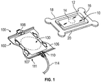
FIG. 1 is an exploded, perspective view of a charging system configured to be coupled to a portable device, according to aspects of the present disclosure; -
FIG. 2 is a rear perspective view of the charging system having a charging mount and a charging module, according to aspects of the present disclosure; -
FIG. 3 is a rear view of the charging system ofFIG. 2 , according to aspects of the present disclosure; -
FIG. 4 is a side elevational view of the charging system ofFIG. 2 , according to aspects of the present disclosure; -
FIG. 5 is a front elevational view of the charging system ofFIG. 2 , according to aspects of the present disclosure; -
FIG. 6 is a perspective view of the charging module ofFIG. 2 omitting a module casing, according to aspects of the present disclosure; -
FIG. 7 is a perspective view of the charging module ofFIG. 2 with the module casing, according to aspects of the present disclosure; -
FIG. 8 is an exploded, rear perspective view of the charging system ofFIG. 2 , according to aspects of the present disclosure; -
FIG. 9 is a cross-sectional side view of the charging mount taken along line 9-9 ofFIG. 8 , according to aspects of the present disclosure; -
FIG. 10 is a cross-sectional side view of another embodiment of the charging mount ofFIG. 9 ; according to aspects of the present disclosure; -
FIG. 11 is a cross-sectional side view of the charging system taken along line 11-11 ofFIG. 2 , according to aspects of the present disclosure; -
FIG. 12 is a perspective, exploded view of the charging system coupled with an external mount, according to aspects of the present disclosure; and -
FIG. 13 is a flow diagram illustrating a method of wireless charging of a portable device, according to aspects of the present disclosure. - Corresponding reference characters indicate corresponding elements among the view of the drawings. The headings used in the figures do not limit the scope of the claims.
- The present disclosure relates to a charging system configured to couple with a portable device and/or a protective case that encases a portable device. In some embodiments, the charging system includes a charging mount to couple with the portable device and/or the protective case of the portable device and a charging module which includes a coil configured to interact with a device coil in the portable device for wireless charging of the portable device. In some embodiments, the charging module may be removably coupled with the charging mount. The construction of the charging mount and the protective case of the portable device are configured such that the coil and the device coil can efficiently interact during a wireless charging. In some embodiments, the charging mount includes a coil receiver which may define a recess or an aperture. In one embodiment, the coil of the charging module may be received within the coil receiver such that the reduced material thickness of the charging module between the coil and the device coil allows for efficient interaction being established between the coil and the device coil for wireless charging. In another embodiment, the coil of the charging module may be received within the coil receiver adjacent an aperture defined by the charging mount for allowing the efficient interaction between the coil and the device coil for wireless charging. Referring to the drawings, embodiments of a charging system are illustrated and generally indicated as 100 in
FIGS. 1-12 . - Referring to
FIG. 1 , an embodiment of a charging system, designated 100, includes acharging mount 102 configured to be removably coupled with aprotective case 16 for aportable device 10. While the present disclosure discusses thecharging system 100 being coupled with theprotective case 16, in some embodiments, thecharging system 100 can also couple directly with theportable device 10. Theportable device 10 includes adevice coil 12 which is disposed within adevice housing 12. In some embodiments, theportable device 10 may be a phone such as a smartphone or a tablet. In some embodiments, theportable device 10 may be encased in aprotective case 16. Theprotective case 16 at least partially surrounds the device housing 12 of theportable device 10. In one aspect, theprotective case 16 may prevent wear of the device housing 12 and/or decrease any force that may be applied to theportable device 10, for example when theportable device 10 is dropped to the ground or receives other types of impacts from an external source. Exemplaryprotective cases 16 are the JUGGERNAUT CASE, the JUGGERNAUT SLEEV, the JUGGERNAUT BUMPR, and the JUGGERNAUT IMPCT; however, the types ofprotective cases 16 are not limited to these specific examples. - Referring to
FIGS. 1-5 , thecharging mount 102 ofcharging system 100 has amount body 106 defining afront surface 107 and an oppositerear surface 111. In some embodiments, thecharging mount 102 includes afirst device coupler 108 and asecond device coupler 110 which extend from opposite respective first andsecond sides mount body 106. In particular, as shown inFIG. 1 , thefirst device coupler 108 is configured to abut afirst side 18 of theprotective case 16 and thesecond coupler 110 is configured to abut thesecond side 20 of theprotective case 16 such that theprotective case 16 is securely engaged to thecharging mount 102. In some embodiments, thefirst device coupler 108 and thesecond device coupler 110 collectively engage with theprotective case 16 by a snap fit connection. For example, when theprotective case 16 is coupled with thecharging mount 106, thefirst device coupler 108 and thesecond device coupler 110 initially engages and deflects away from the first andsecond sides protective case 16 and then the first andsecond device couplers protective case 16 becomes fully engaged with thecharging mount 106. As such, unlike conventional magnetic coupling, thecharging mount 106 is physically coupled with theprotective case 16 and/or theportable device 10 even if theprotective case 16 and/or theportable device 10 is moved or experiences an external force. Other suitable methods for coupling thecharging mount 106 with theprotective case 16 may be utilized. When thecharging mount 106 is coupled with theprotective case 16, thefront surface 107 of themount body 106 is positioned directly adjacent to theprotective case 16. In some embodiments, themount body 106 may be made of a plastic. In some embodiments, themount body 106 may be made of acrylonitrile butadiene styrene and/or polycarbonate. - Referring specifically to
FIG. 1 , thecharging system 100 may also include acoil 130 of thecharging module 104 that is configured to interact with thedevice coil 14 of theportable device 10 for allowing wireless charging of theportable device 10. In some embodiments, the operative interaction between thecoil 130 and thedevice coil 14 is electromagnetic induction. In some embodiments, thecoil 130 of thecharging module 104 functions as a transmitting coil. In addition, thecoil 130 generates an oscillating magnetic field such that the magnetic field induces an alternating current in a receiving coil, for example thedevice coil 14. As such, thecoil 130 and thedevice coil 14 collectively provide inductive charging of theportable device 10. For example, thecoil 130 and thedevice coil 14 may provide a voltage up to 5 volts and a current up to 2 amperes during charging of theportable device 10. In some embodiments, the inductive charging of theportable device 10 operates under the QI standard. Thecoil 130 and thedevice coil 14 must be within a predetermined distance to properly interact and allow for wireless charging. In some instances, theprotective case 16 may be large and add bulk or size that surrounds the encasedportable device 10, which can necessarily increase the distance between thecoil 130 and thedevice coil 14 and thereby prevent the wireless charging system from properly interacting withportable devices 10 engaged to thecharging mount 104. As such, thecharging system 100 as discussed herein minimizes the distance between thecoil 130 and thedevice coil 14 to allow for the efficient wireless charging ofportable devices 10 encased inprotective cases 16. - Referring to
FIGS. 2 and3 , therear surface 111 of themount body 106 is configured to receive acharging module 104. In some embodiments, thecharging module 104 includes thecoil 130 for wireless charging theportable device 10. As shown, thecharging module 104 also includes aconnector 114 which can transfer data and/or power to and from thecharging module 104. In some embodiments, theconnector 114 may be a USB A cable. In other embodiments, theconnector 114 may be a USB C cable, a lightning cable, a mini-USB cable, or any other suitable connector to transfer data and/or power. In some embodiments, theconnector 114 may be removably coupled with thecharging module 104. When theconnector 114 is coupled with thecharging module 104, fluid is prevented from communicating across the connection of theconnector 114 and thecharging module 104 such that the connection is substantially waterproof. In other embodiments, theconnector 114 may be fixedly coupled with thecharging module 104 by soldering or any other suitable method of attachment. Theconnector 114 may be overmolded such that fluid is prevented from communicating across the connection of theconnector 114 and thecharging module 104. As such, the connection is substantially waterproof. - A plurality of
external fasteners 112 extend from therear surface 111 of themount body 106 with eachexternal fastener 112 being configured to correspond with and engage anexternal mount 132 as illustrated inFIG. 10 when coupling the chargingmount 102 to theexternal mount 132. As shown inFIGS. 2 and3 , in some embodiments the chargingmount 102 includes fourexternal fasteners 112; however, in other embodiments, one, two, three, five, or moreexternal fasteners 112 may be included as desired. - Referring to
FIGS. 6 and 7 , in some embodiments thecharging module 104 includes acircuit board 128, acoil 130 coupled with thecircuit board 128, and aconnector 114 which is also coupled with thecircuit board 128. Thecoil 130 as illustrated is substantially circular. In other embodiments, thecoil 130 may be substantially rectangular, ovoid, triangular, or any other suitable shape.FIG. 6 illustrates thecharging module 104 omitting a module casing, andFIG. 7 illustrates thecharging module 104 with amodule casing 116. - In some embodiments, the
module casing 116 includes an overmolded polymer surrounding thecoil 130, thecircuit board 128, and at least a portion of theconnector 114. In some embodiments, the overmolded polymer of themodule casing 116 is a thermoplastic material, for example a thermoplastic elastomer. In some embodiments, the overmolded polymer of themodule casing 116 may be potted with an epoxy. In some embodiments, themodule casing 116 is waterproof such that fluid communication across themodule casing 116 with thecoil 130 and/or thecircuit board 128 is prevented. Thecoil 130 and/or thecircuit board 128 can be encapsulated with theovermolded module casing 116. An epoxy may then be used to pot any holes caused by the overmolding tool to achieve awaterproof module casing 116. In some embodiments, themodule casing 116 of thecharging module 104 may be rated at IP58 or better, where an IP58 rating means that thecharging module 104 is dust resistant and can be immersed in 1.5 meters of freshwater for up to 30 minutes. In some embodiments, themodule casing 116 of thecharging module 104 may be rated at IP67 or better, where an IP67 rating means that thecharging module 104 is dust tight such that there is no ingress of dust and can be immersed in up to 1 meter of freshwater for up to 30 minutes. - In some embodiments, the
module casing 116 is rugged such that thecharging module 104 can function under high environmental stresses. In some embodiments, environmental stresses may be, for example, extreme temperatures, vibrations, shock, high altitude, and/or humidity. For example, thecharging module 104 may function in temperatures ranging from about -50°C to 100°C, vibration of up to about 2000Hz, altitude up to about 70,000feet, and/or humidity up to about 100%. - Referring to
FIG. 8 , thecharging module 104 is removably coupled with the chargingmount 102. In some embodiments, the chargingmount 102 includes amodule receiver 122 configured to receive thecharging module 104. In some embodiments, themodule casing 116 of thecharging module 104 defines afront side 117 which is sized and shaped, when thecharging module 104 is received within themodule receiver 122, is positioned directly adjacent to the chargingmount 102. In some embodiments, themodule casing 116 defines arear side 119 which is formed opposite thefront side 117. The chargingmount 102 may include extendingwalls 124 which extend outwardly from therear surface 111 of themount body 106. When thecharging module 104 is received within themodule receiver 122, thewalls 124 surround at least a portion of thecharging module 104 to limit the movement of thecharging module 104. - The charging
mount 102 may also include one ormore mount couplers 120 having arespective tang 123 formed at the free end thereof which is sized and shaped to correspond withmodule couplers 118 that definerecesses 125 configured to receive and engage arespective tang 123 to couple thecharging module 104 with the chargingmount 102. In some embodiments, themodule couplers 118 may be positioned along therear side 119 of themodule casing 116. In one aspect, the chargingmount 102 and thecharging module 104 may be removably coupled. When installing thecharging module 104, thetang 123 of eachmount coupler 120 may initially deflect when abutting themodule casing 116 and then engage arespective recess 125 for establishing a snap fit connection between the chargingmodule 102 and thecharging unit 104. Other suitable methods for coupling the chargingmount 102 with thecharging module 104 may be utilized as desired, such as a threaded engagement or a hook and fastener engagement. - Referring to
FIGS. 8-11 , themodule receiver 122 includes acoil receiver 126. Thecoil 130, when thecharging module 104 is installed within themodule receiver 126, is positioned within thecoil receiver 126. In some embodiments, the shape of thecoil receiver 126 may correspond to the shape of the portion of thecharging module 104 which contains thecoil 130. In some embodiments, thecharging module 104 may not include a separate portion or shape for thecoil 130, and thecoil receiver 126 and themodule receiver 122 may be the same feature. - Referring to
FIG. 9 , in some embodiments thecoil receiver 126 can define a recess 127. Themount body 106 defines a thickness T1 which is greater than a thickness T2 of themount body 106 which corresponds with thecoil receiver 126. As further shown inFIG. 9 , the recess 127 is defined as themount body 106 and defines a thickness T2 which is greater than zero. When the thickness T2 is zero, thecoil receiver 126 defines an aperture 227, as shown inFIG. 10 . - As shown in
FIG. 11 , thecoil receiver 126 extends toward thefront surface 107 of the chargingmount 102 so that a distance D1 defined between thefront surface 107 of the chargingmount 102 and thecoil receiver 126 is less than a distance D2 defined between thefront surface 107 of the chargingmount 102 and therear surface 111 of the chargingmount 102. As such, when thecoil 130 is positioned in thecoil receiver 126, a distance D3 defined betweencoil 130 and thefront surface 107 of the chargingmount 102 and subsequently a distance D4 defined between thecoil 130 and thedevice coil 14, are minimized to allow for improved interaction between thecoil 130 and thedevice coil 14 during a wireless charging operation. In some embodiments, the distance D4 defined between thecoil 130 and thedevice coil 14 to allow for greater operative interaction between thecoil 130 and thedevice coil 14 may be equal to or less than about 6mm. In some embodiments, a thickness of at least a portion of thefront side 117 of themodule casing 104 may be reduced in relation to therear side 119 of themodule casing 104 to further minimize the distance D4 between thecoil 130 and thedevice coil 14. - Referring to
FIG. 12 , in one aspect thecharging system 100 may be coupled with anexternal mount 132 to mount thecharging system 100 and the portable device 10 (such as theportable device 10 illustrated inFIG. 1 ), for example on a vehicle. As such, theportable device 10 may be used in a hands-free mode. In some embodiments, theexternal mount 132 may have one ormore arms 134. The arm, as illustrated inFIG. 12 , includes aplate 135. Theplate 135, as illustrated, is substantially rectangular, but in other embodiments can be any other suitable shape such as circular, triangular, or ovoid. Theplate 135 includes one ormore holes 137. Theholes 137 are aligned with theexternal fasteners 112 positioned on therear surface 111 of themount body 106. Theexternal mount 132, as illustrated inFIG. 12 , includesfasteners 136 which are configured to correspond with theexternal fasteners 112 of themount body 106. Thefasteners 136 are inserted into and extend through theholes 137 to engage with theexternal fasteners 112. Thefasteners 136 can be removed from theexternal mount 132. In some embodiments, theexternal mount 132 can include a plurality ofarms 134, and eacharm 134 includes one ormore holes 137 and/orfasteners 136. In some embodiments, theexternal mount 132 may not include aplate 135. In some embodiments, theexternal mount 132 may have not haveholes 137, and thefasteners 136 may be non-removable portions of theexternal mount 132. - As illustrated in
FIG. 12 , theexternal mount 132 includes 4holes 137 formed on theplate 135 and 4corresponding fasteners 136. In some embodiments, thefasteners 136 andexternal fasteners 112 may have threaded engagements. In other embodiments, thefasteners 136 andexternal fasteners 112 may have snap fit connections. Thefasteners 136 andexternal fasteners 112 may also be magnetic. Other suitable methods to couple the chargingmount 102 with theexternal mount 132 may be utilized as desired, such as a hook and fastener engagement or an adhesive connection. - Referring to
FIG. 13 , a flowchart is presented in accordance with an example embodiment. Themethod 300 is provided by way of example, as there are a variety of ways to carry out the method. Themethod 300 described below can be carried out using the configurations illustrated inFIGS. 1-12 , for example, and various elements of these figures are referenced in explainingexample method 300. Each step shown inFIG. 13 represents one or more processes, methods or subroutines, carried out in theexample method 300. Furthermore, the illustrated order of blocks is illustrative only and the order of the blocks can change according to the present disclosure. Additional steps may be added or fewer blocks may be utilized, without departing from this disclosure. Theexample method 300 can begin atstep 302. - At
step 302, a chargingmount 102 is provided. The chargingmount 102 may include amount body 106 which defines arear surface 111 and afront surface 107 defined in opposite relation to therear surface 111. Therear surface 111 and thefront surface 107 of themount body 106 define a first thickness T1. Therear surface 111 of themount body 106 includes amodule receiver 122 with acoil receiver 126. Themount body 106 corresponds with thecoil receiver 126 and defines a second thickness T2 which is less than the first thickness T1. In some embodiments, as illustrated inFIG. 9 , the second thickness T2 may be greater than zero, and thecoil receiver 126 may define a recess 127. In other embodiments, as illustrated inFIG. 10 , the second thickness T2 may be zero, and thecoil receiver 126 may define an aperture 227. - At
step 304, the chargingmount 102 is engaged with aportable device 10. In some embodiments,portable device 10 may be encased in aprotective case 16, and the chargingmount 102 may be engaged with theprotective case 16. Theportable device 10 includes adevice coil 14. When engaged, thefront surface 107 of themount body 106 is engaged with theportable device 10 such that thefront surface 107 of themount body 106 is positioned adjacent to theportable device 10. - At
step 306, acharging module 104 is positioned within themodule receiver 122 provided on therear surface 111 of themount body 106. Thecharging module 104 includes acoil 130 which is configured to interact with thedevice coil 14 to wireless charge theportable device 10. - To minimize the distance D4 between the
coil 130 and thedevice coil 14, atstep 308, thecoil 130 is positioned within thecoil receiver 126. - At
step 310, thecharging module 104 is coupled with the chargingmount 102. In some embodiments, thecharging module 104 may be coupled with the chargingmount 102 by a snap fit connection or other suitable methods as discussed above. - At
step 312, theportable device 10 is wirelessly charged with thecharging module 104 by the interaction of thecoil 130 and thedevice coil 14. The smaller the distance D4 between thecoil 130 and thedevice coil 14, the more efficiently and/or effectively theportable device 10 is charged. - In some embodiments, the charging
mount 102 can also be coupled with anexternal mount 132 by one or moreexternal fasteners 112 positioned on therear surface 111 of themount body 106 as discussed above. - It should be understood from the foregoing that, while particular embodiments have been illustrated and described, various modifications can be made thereto without departing from the spirit and scope of the invention as will be apparent to those skilled in the art. Such changes and modifications are within the scope and teachings of this invention as defined in the claims appended hereto.
Claims (15)
- A system comprising:a portable device having a device coil;a charging mount with a mount body defining a rear surface and a front surface defined in opposite relation to the rear surface, the rear surface and the front surface of the mount body defining a first thickness, the front surface of the mount body configured to be engaged with the portable device such that the front surface of the mount body is positioned adjacent to the portable device, the rear surface of the mount body including a module receiver with a coil receiver, the mount body corresponding with the coil receiver defining a second thickness which is less than the first thickness; anda charging module removably coupled with the charging mount and positioned within the module receiver, the charging module including a coil operable to interact with the device coil of the portable device to wirelessly charge the portable device, the coil being positioned within the coil receiver.
- The system of claim 1, wherein the coil receiver defines a recess or an aperture.
- The system of claim 1 or claim 2, wherein the distance between the coil and the device coil is equal to or less than about 6 mm.
- The system of any preceding claim, wherein the charging module comprises a module casing, the module casing defining a front side and a rear side,
wherein the front side of the module casing, when the charging module is coupled with the charging mount, is adjacent to the rear surface of the charging mount. - The system of claim 4, wherein the module casing includes an overmolded polymer surrounding the coil, and /or wherein the module casing is waterproof such that fluid communication with the coil is prevented.
- The system of any preceding claim, wherein the charging mount includes one or more external fasteners positioned on the rear surface of the charging mount, the one or more external fasteners configured to couple the charging mount with an external mount.
- The system of any preceding claim, wherein the charging module removably couples with the charging mount by snap fit connection.
- A charging system configured to couple to and wireless charge a portable device having a device coil, the charging system comprising:a charging mount with a mount body defining a rear surface and a front surface defined in opposite relation to the rear surface, the rear surface and the front surface of the mount body defining a first thickness, the front surface of the mount body configured to be engaged with the portable device such that the front surface of the mount body is positioned adjacent to the portable device, the rear surface of the mount body including a module receiver with a coil receiver, the mount body corresponding with the coil receiver defining a second thickness which is less than the first thickness; anda charging module removably coupled with the charging mount and positioned within the module receiver, the charging module including a coil operable to interact with the device coil of the portable device to wirelessly charge the portable device, the coil being positioned within the coil receiver.
- The charging system of claim 8, wherein the coil receiver defines a recess or an aperture.
- The charging system of claim 8 or claim 9, wherein the distance between the coil and the device coil is equal to or less than about 6 mm.
- The charging system of any one of claims 8 to 10, wherein the charging module comprises a module casing, the module casing defining a front side and a rear side, wherein the front side of the module casing, when the charging module is coupled with the charging mount, is adjacent to the rear surface of the charging mount.
- The charging system of claim 11, wherein the module casing includes an overmolded polymer surrounding the coil, and/or wherein the module casing is waterproof such that fluid communication with the coil is prevented.
- The charging system of any one of claims 8 to 12, wherein the charging mount includes one or more external fasteners positioned on the rear surface of the charging mount, the one or more external fasteners configured to couple the charging mount with an external mount.
- The charging system of any one of claims 8 to 13, wherein the charging module removably couples with the charging mount by snap fit connection.
- A method of wireless charging a portable device with a device coil, the method comprising:providing a charging mount with a mount body defining a rear surface and a front surface defined in opposite relation to the rear surface, the rear surface and the front surface of the mount body defining a first thickness, the rear surface of the mount body including a module receiver with a coil receiver, the mount body corresponding with the coil receiver defining a second thickness which is less than the first thickness;engaging the charging mount with the portable device, the front surface of the mount body engaged with the portable device such that the front surface of the mount body is positioned adjacent to the portable device;positioning a charging module within the module receiver provided on the rear surface of the mount body, the charging module including a coil;positioning the coil within the coil receiver;coupling the charging module with the charging mount; andcharging, wirelessly, the portable device with the charging module by the interaction of the coil and the device coilwherein, optionally, the charging mount includes one or more external fasteners positioned on the rear surface of the mount body, the method optionally further comprising: coupling the charging mount with an external mount by the one or more external fasteners.
Applications Claiming Priority (1)
| Application Number | Priority Date | Filing Date | Title |
|---|---|---|---|
| US16/122,677 US10938230B2 (en) | 2018-09-05 | 2018-09-05 | Systems and methods for a wireless charging mount |
Publications (2)
| Publication Number | Publication Date |
|---|---|
| EP3621177A1 true EP3621177A1 (en) | 2020-03-11 |
| EP3621177B1 EP3621177B1 (en) | 2024-11-06 |
Family
ID=67874288
Family Applications (1)
| Application Number | Title | Priority Date | Filing Date |
|---|---|---|---|
| EP19195526.9A Active EP3621177B1 (en) | 2018-09-05 | 2019-09-05 | Systems and methods for a wireless charging mount |
Country Status (3)
| Country | Link |
|---|---|
| US (1) | US10938230B2 (en) |
| EP (1) | EP3621177B1 (en) |
| CA (1) | CA3052585A1 (en) |
Families Citing this family (2)
| Publication number | Priority date | Publication date | Assignee | Title |
|---|---|---|---|---|
| USD976887S1 (en) * | 2019-01-08 | 2023-01-31 | Juggernaut Defense, Llc | Mount and module combination for a mobile communications device |
| WO2021232417A1 (en) * | 2020-05-22 | 2021-11-25 | 广东高普达集团股份有限公司 | Wireless charger |
Citations (2)
| Publication number | Priority date | Publication date | Assignee | Title |
|---|---|---|---|---|
| US20130244735A1 (en) * | 2012-03-13 | 2013-09-19 | Bury Sp.Z.O.O. | Holder for a Mobile Telephone |
| US20160036478A1 (en) * | 2014-07-29 | 2016-02-04 | Chih-Juh Wong | Wireless charging stand |
Family Cites Families (3)
| Publication number | Priority date | Publication date | Assignee | Title |
|---|---|---|---|---|
| KR100566220B1 (en) * | 2001-01-05 | 2006-03-29 | 삼성전자주식회사 | Solid state battery charger |
| CN101841173B (en) * | 2009-03-19 | 2013-04-24 | 鸿富锦精密工业(深圳)有限公司 | Charging system |
| US20150069965A1 (en) * | 2013-09-12 | 2015-03-12 | E I Du Pont De Nemours And Company | Embeddable wireless charger |
-
2018
- 2018-09-05 US US16/122,677 patent/US10938230B2/en active Active
-
2019
- 2019-08-20 CA CA3052585A patent/CA3052585A1/en not_active Abandoned
- 2019-09-05 EP EP19195526.9A patent/EP3621177B1/en active Active
Patent Citations (2)
| Publication number | Priority date | Publication date | Assignee | Title |
|---|---|---|---|---|
| US20130244735A1 (en) * | 2012-03-13 | 2013-09-19 | Bury Sp.Z.O.O. | Holder for a Mobile Telephone |
| US20160036478A1 (en) * | 2014-07-29 | 2016-02-04 | Chih-Juh Wong | Wireless charging stand |
Also Published As
| Publication number | Publication date |
|---|---|
| US10938230B2 (en) | 2021-03-02 |
| US20200076219A1 (en) | 2020-03-05 |
| CA3052585A1 (en) | 2020-03-05 |
| EP3621177B1 (en) | 2024-11-06 |
Similar Documents
| Publication | Publication Date | Title |
|---|---|---|
| EP3038439B1 (en) | Electronic assembly having a circuit board with a shock absorber device | |
| US10326488B2 (en) | Electronic device case with inductive coupling features | |
| EP3621177B1 (en) | Systems and methods for a wireless charging mount | |
| EP2950386A1 (en) | Communication antenna unit and mobile terminal apparatus | |
| CN111315613A (en) | Charging cable and adapter for charging a stored energy source at an energy supply device | |
| US12119598B1 (en) | Universal DC power adaptor | |
| EP2693591A1 (en) | Wireless Power Transmission Device | |
| US12191703B2 (en) | Wireless mobile battery | |
| KR20110103395A (en) | Wireless Power Supply and Near Field Communication in Electronic Devices | |
| AU2021204097A1 (en) | Mobile Device Charger | |
| EP3246666A1 (en) | Sensor unit and magnetism collecting module and sensor apparatus | |
| US20120235868A1 (en) | Antenna structure and portable communication terminal | |
| US10594352B2 (en) | Protective case for a mobile terminal | |
| EP2944074B1 (en) | Wireless charging device and method using the same | |
| US20180269720A1 (en) | Power transmission device | |
| US20170093196A1 (en) | Rechargeable Battery Induction System and Methods of Making and Using the Same | |
| US20240180306A1 (en) | Protective case with removable functional modules | |
| CN215322058U (en) | Installation casing, intelligent charging stake and battery charging outfit | |
| EP3515084B1 (en) | Corrosion resistant telecommunications enclosure | |
| KR20230097634A (en) | Fuse box integrated connector block | |
| CN219577266U (en) | Near field communication device | |
| CN210402020U (en) | Developing box | |
| CN219718686U (en) | Edge calculation box for unmanned aerial vehicle | |
| KR20160118778A (en) | Wireless Charge Patch Module | |
| CN220934376U (en) | Antenna assembly and mobile terminal |
Legal Events
| Date | Code | Title | Description |
|---|---|---|---|
| PUAI | Public reference made under article 153(3) epc to a published international application that has entered the european phase |
Free format text: ORIGINAL CODE: 0009012 |
|
| STAA | Information on the status of an ep patent application or granted ep patent |
Free format text: STATUS: THE APPLICATION HAS BEEN PUBLISHED |
|
| AK | Designated contracting states |
Kind code of ref document: A1 Designated state(s): AL AT BE BG CH CY CZ DE DK EE ES FI FR GB GR HR HU IE IS IT LI LT LU LV MC MK MT NL NO PL PT RO RS SE SI SK SM TR |
|
| AX | Request for extension of the european patent |
Extension state: BA ME |
|
| STAA | Information on the status of an ep patent application or granted ep patent |
Free format text: STATUS: REQUEST FOR EXAMINATION WAS MADE |
|
| 17P | Request for examination filed |
Effective date: 20200911 |
|
| RBV | Designated contracting states (corrected) |
Designated state(s): AL AT BE BG CH CY CZ DE DK EE ES FI FR GB GR HR HU IE IS IT LI LT LU LV MC MK MT NL NO PL PT RO RS SE SI SK SM TR |
|
| STAA | Information on the status of an ep patent application or granted ep patent |
Free format text: STATUS: EXAMINATION IS IN PROGRESS |
|
| 17Q | First examination report despatched |
Effective date: 20211209 |
|
| GRAP | Despatch of communication of intention to grant a patent |
Free format text: ORIGINAL CODE: EPIDOSNIGR1 |
|
| STAA | Information on the status of an ep patent application or granted ep patent |
Free format text: STATUS: GRANT OF PATENT IS INTENDED |
|
| INTG | Intention to grant announced |
Effective date: 20240327 |
|
| GRAJ | Information related to disapproval of communication of intention to grant by the applicant or resumption of examination proceedings by the epo deleted |
Free format text: ORIGINAL CODE: EPIDOSDIGR1 |
|
| STAA | Information on the status of an ep patent application or granted ep patent |
Free format text: STATUS: EXAMINATION IS IN PROGRESS |
|
| GRAP | Despatch of communication of intention to grant a patent |
Free format text: ORIGINAL CODE: EPIDOSNIGR1 |
|
| STAA | Information on the status of an ep patent application or granted ep patent |
Free format text: STATUS: GRANT OF PATENT IS INTENDED |
|
| INTC | Intention to grant announced (deleted) | ||
| INTG | Intention to grant announced |
Effective date: 20240723 |
|
| GRAS | Grant fee paid |
Free format text: ORIGINAL CODE: EPIDOSNIGR3 |
|
| P01 | Opt-out of the competence of the unified patent court (upc) registered |
Free format text: CASE NUMBER: APP_45654/2024 Effective date: 20240806 |
|
| GRAA | (expected) grant |
Free format text: ORIGINAL CODE: 0009210 |
|
| STAA | Information on the status of an ep patent application or granted ep patent |
Free format text: STATUS: THE PATENT HAS BEEN GRANTED |
|
| AK | Designated contracting states |
Kind code of ref document: B1 Designated state(s): AL AT BE BG CH CY CZ DE DK EE ES FI FR GB GR HR HU IE IS IT LI LT LU LV MC MK MT NL NO PL PT RO RS SE SI SK SM TR |
|
| REG | Reference to a national code |
Ref country code: GB Ref legal event code: FG4D |
|
| REG | Reference to a national code |
Ref country code: CH Ref legal event code: EP |
|
| REG | Reference to a national code |
Ref country code: DE Ref legal event code: R096 Ref document number: 602019061410 Country of ref document: DE |
|
| REG | Reference to a national code |
Ref country code: IE Ref legal event code: FG4D |
|
| REG | Reference to a national code |
Ref country code: LT Ref legal event code: MG9D |
|
| REG | Reference to a national code |
Ref country code: NL Ref legal event code: MP Effective date: 20241106 |
|
| PG25 | Lapsed in a contracting state [announced via postgrant information from national office to epo] |
Ref country code: HR Free format text: LAPSE BECAUSE OF FAILURE TO SUBMIT A TRANSLATION OF THE DESCRIPTION OR TO PAY THE FEE WITHIN THE PRESCRIBED TIME-LIMIT Effective date: 20241106 Ref country code: PT Free format text: LAPSE BECAUSE OF FAILURE TO SUBMIT A TRANSLATION OF THE DESCRIPTION OR TO PAY THE FEE WITHIN THE PRESCRIBED TIME-LIMIT Effective date: 20250306 Ref country code: IS Free format text: LAPSE BECAUSE OF FAILURE TO SUBMIT A TRANSLATION OF THE DESCRIPTION OR TO PAY THE FEE WITHIN THE PRESCRIBED TIME-LIMIT Effective date: 20250306 |
|
| PG25 | Lapsed in a contracting state [announced via postgrant information from national office to epo] |
Ref country code: NL Free format text: LAPSE BECAUSE OF FAILURE TO SUBMIT A TRANSLATION OF THE DESCRIPTION OR TO PAY THE FEE WITHIN THE PRESCRIBED TIME-LIMIT Effective date: 20241106 Ref country code: FI Free format text: LAPSE BECAUSE OF FAILURE TO SUBMIT A TRANSLATION OF THE DESCRIPTION OR TO PAY THE FEE WITHIN THE PRESCRIBED TIME-LIMIT Effective date: 20241106 |
|
| REG | Reference to a national code |
Ref country code: AT Ref legal event code: MK05 Ref document number: 1740469 Country of ref document: AT Kind code of ref document: T Effective date: 20241106 |
|
| PG25 | Lapsed in a contracting state [announced via postgrant information from national office to epo] |
Ref country code: BG Free format text: LAPSE BECAUSE OF FAILURE TO SUBMIT A TRANSLATION OF THE DESCRIPTION OR TO PAY THE FEE WITHIN THE PRESCRIBED TIME-LIMIT Effective date: 20241106 |
|
| PG25 | Lapsed in a contracting state [announced via postgrant information from national office to epo] |
Ref country code: ES Free format text: LAPSE BECAUSE OF FAILURE TO SUBMIT A TRANSLATION OF THE DESCRIPTION OR TO PAY THE FEE WITHIN THE PRESCRIBED TIME-LIMIT Effective date: 20241106 |
|
| PG25 | Lapsed in a contracting state [announced via postgrant information from national office to epo] |
Ref country code: NO Free format text: LAPSE BECAUSE OF FAILURE TO SUBMIT A TRANSLATION OF THE DESCRIPTION OR TO PAY THE FEE WITHIN THE PRESCRIBED TIME-LIMIT Effective date: 20250206 |
|
| PG25 | Lapsed in a contracting state [announced via postgrant information from national office to epo] |
Ref country code: GR Free format text: LAPSE BECAUSE OF FAILURE TO SUBMIT A TRANSLATION OF THE DESCRIPTION OR TO PAY THE FEE WITHIN THE PRESCRIBED TIME-LIMIT Effective date: 20250207 Ref country code: LV Free format text: LAPSE BECAUSE OF FAILURE TO SUBMIT A TRANSLATION OF THE DESCRIPTION OR TO PAY THE FEE WITHIN THE PRESCRIBED TIME-LIMIT Effective date: 20241106 Ref country code: AT Free format text: LAPSE BECAUSE OF FAILURE TO SUBMIT A TRANSLATION OF THE DESCRIPTION OR TO PAY THE FEE WITHIN THE PRESCRIBED TIME-LIMIT Effective date: 20241106 |
|
| PG25 | Lapsed in a contracting state [announced via postgrant information from national office to epo] |
Ref country code: PL Free format text: LAPSE BECAUSE OF FAILURE TO SUBMIT A TRANSLATION OF THE DESCRIPTION OR TO PAY THE FEE WITHIN THE PRESCRIBED TIME-LIMIT Effective date: 20241106 |
|
| PG25 | Lapsed in a contracting state [announced via postgrant information from national office to epo] |
Ref country code: RS Free format text: LAPSE BECAUSE OF FAILURE TO SUBMIT A TRANSLATION OF THE DESCRIPTION OR TO PAY THE FEE WITHIN THE PRESCRIBED TIME-LIMIT Effective date: 20250206 |
|
| PG25 | Lapsed in a contracting state [announced via postgrant information from national office to epo] |
Ref country code: SM Free format text: LAPSE BECAUSE OF FAILURE TO SUBMIT A TRANSLATION OF THE DESCRIPTION OR TO PAY THE FEE WITHIN THE PRESCRIBED TIME-LIMIT Effective date: 20241106 |
|
| PG25 | Lapsed in a contracting state [announced via postgrant information from national office to epo] |
Ref country code: DK Free format text: LAPSE BECAUSE OF FAILURE TO SUBMIT A TRANSLATION OF THE DESCRIPTION OR TO PAY THE FEE WITHIN THE PRESCRIBED TIME-LIMIT Effective date: 20241106 |
|
| PG25 | Lapsed in a contracting state [announced via postgrant information from national office to epo] |
Ref country code: EE Free format text: LAPSE BECAUSE OF FAILURE TO SUBMIT A TRANSLATION OF THE DESCRIPTION OR TO PAY THE FEE WITHIN THE PRESCRIBED TIME-LIMIT Effective date: 20241106 |
|
| PG25 | Lapsed in a contracting state [announced via postgrant information from national office to epo] |
Ref country code: RO Free format text: LAPSE BECAUSE OF FAILURE TO SUBMIT A TRANSLATION OF THE DESCRIPTION OR TO PAY THE FEE WITHIN THE PRESCRIBED TIME-LIMIT Effective date: 20241106 |
|
| PG25 | Lapsed in a contracting state [announced via postgrant information from national office to epo] |
Ref country code: SK Free format text: LAPSE BECAUSE OF FAILURE TO SUBMIT A TRANSLATION OF THE DESCRIPTION OR TO PAY THE FEE WITHIN THE PRESCRIBED TIME-LIMIT Effective date: 20241106 |
|
| PG25 | Lapsed in a contracting state [announced via postgrant information from national office to epo] |
Ref country code: CZ Free format text: LAPSE BECAUSE OF FAILURE TO SUBMIT A TRANSLATION OF THE DESCRIPTION OR TO PAY THE FEE WITHIN THE PRESCRIBED TIME-LIMIT Effective date: 20241106 |
|
| PG25 | Lapsed in a contracting state [announced via postgrant information from national office to epo] |
Ref country code: IT Free format text: LAPSE BECAUSE OF FAILURE TO SUBMIT A TRANSLATION OF THE DESCRIPTION OR TO PAY THE FEE WITHIN THE PRESCRIBED TIME-LIMIT Effective date: 20241106 |
|
| REG | Reference to a national code |
Ref country code: DE Ref legal event code: R097 Ref document number: 602019061410 Country of ref document: DE |
|
| PG25 | Lapsed in a contracting state [announced via postgrant information from national office to epo] |
Ref country code: SE Free format text: LAPSE BECAUSE OF FAILURE TO SUBMIT A TRANSLATION OF THE DESCRIPTION OR TO PAY THE FEE WITHIN THE PRESCRIBED TIME-LIMIT Effective date: 20241106 |
|
| PLBE | No opposition filed within time limit |
Free format text: ORIGINAL CODE: 0009261 |
|
| STAA | Information on the status of an ep patent application or granted ep patent |
Free format text: STATUS: NO OPPOSITION FILED WITHIN TIME LIMIT |
|
| 26N | No opposition filed |
Effective date: 20250807 |